EP1956580A1 - Display panel - Google Patents
Display panel Download PDFInfo
- Publication number
- EP1956580A1 EP1956580A1 EP06126382A EP06126382A EP1956580A1 EP 1956580 A1 EP1956580 A1 EP 1956580A1 EP 06126382 A EP06126382 A EP 06126382A EP 06126382 A EP06126382 A EP 06126382A EP 1956580 A1 EP1956580 A1 EP 1956580A1
- Authority
- EP
- European Patent Office
- Prior art keywords
- display panel
- panel according
- light
- microcontrollers
- pixel
- Prior art date
- Legal status (The legal status is an assumption and is not a legal conclusion. Google has not performed a legal analysis and makes no representation as to the accuracy of the status listed.)
- Withdrawn
Links
Images


Classifications
-
- G—PHYSICS
- G09—EDUCATION; CRYPTOGRAPHY; DISPLAY; ADVERTISING; SEALS
- G09G—ARRANGEMENTS OR CIRCUITS FOR CONTROL OF INDICATING DEVICES USING STATIC MEANS TO PRESENT VARIABLE INFORMATION
- G09G3/00—Control arrangements or circuits, of interest only in connection with visual indicators other than cathode-ray tubes
- G09G3/20—Control arrangements or circuits, of interest only in connection with visual indicators other than cathode-ray tubes for presentation of an assembly of a number of characters, e.g. a page, by composing the assembly by combination of individual elements arranged in a matrix no fixed position being assigned to or needed to be assigned to the individual characters or partial characters
- G09G3/22—Control arrangements or circuits, of interest only in connection with visual indicators other than cathode-ray tubes for presentation of an assembly of a number of characters, e.g. a page, by composing the assembly by combination of individual elements arranged in a matrix no fixed position being assigned to or needed to be assigned to the individual characters or partial characters using controlled light sources
- G09G3/30—Control arrangements or circuits, of interest only in connection with visual indicators other than cathode-ray tubes for presentation of an assembly of a number of characters, e.g. a page, by composing the assembly by combination of individual elements arranged in a matrix no fixed position being assigned to or needed to be assigned to the individual characters or partial characters using controlled light sources using electroluminescent panels
- G09G3/32—Control arrangements or circuits, of interest only in connection with visual indicators other than cathode-ray tubes for presentation of an assembly of a number of characters, e.g. a page, by composing the assembly by combination of individual elements arranged in a matrix no fixed position being assigned to or needed to be assigned to the individual characters or partial characters using controlled light sources using electroluminescent panels semiconductive, e.g. using light-emitting diodes [LED]
-
- B—PERFORMING OPERATIONS; TRANSPORTING
- B32—LAYERED PRODUCTS
- B32B—LAYERED PRODUCTS, i.e. PRODUCTS BUILT-UP OF STRATA OF FLAT OR NON-FLAT, e.g. CELLULAR OR HONEYCOMB, FORM
- B32B17/00—Layered products essentially comprising sheet glass, or glass, slag, or like fibres
- B32B17/06—Layered products essentially comprising sheet glass, or glass, slag, or like fibres comprising glass as the main or only constituent of a layer, next to another layer of a specific material
- B32B17/10—Layered products essentially comprising sheet glass, or glass, slag, or like fibres comprising glass as the main or only constituent of a layer, next to another layer of a specific material of synthetic resin
- B32B17/10005—Layered products essentially comprising sheet glass, or glass, slag, or like fibres comprising glass as the main or only constituent of a layer, next to another layer of a specific material of synthetic resin laminated safety glass or glazing
- B32B17/10009—Layered products essentially comprising sheet glass, or glass, slag, or like fibres comprising glass as the main or only constituent of a layer, next to another layer of a specific material of synthetic resin laminated safety glass or glazing characterized by the number, the constitution or treatment of glass sheets
- B32B17/10036—Layered products essentially comprising sheet glass, or glass, slag, or like fibres comprising glass as the main or only constituent of a layer, next to another layer of a specific material of synthetic resin laminated safety glass or glazing characterized by the number, the constitution or treatment of glass sheets comprising two outer glass sheets
-
- B—PERFORMING OPERATIONS; TRANSPORTING
- B32—LAYERED PRODUCTS
- B32B—LAYERED PRODUCTS, i.e. PRODUCTS BUILT-UP OF STRATA OF FLAT OR NON-FLAT, e.g. CELLULAR OR HONEYCOMB, FORM
- B32B17/00—Layered products essentially comprising sheet glass, or glass, slag, or like fibres
- B32B17/06—Layered products essentially comprising sheet glass, or glass, slag, or like fibres comprising glass as the main or only constituent of a layer, next to another layer of a specific material
- B32B17/10—Layered products essentially comprising sheet glass, or glass, slag, or like fibres comprising glass as the main or only constituent of a layer, next to another layer of a specific material of synthetic resin
- B32B17/10005—Layered products essentially comprising sheet glass, or glass, slag, or like fibres comprising glass as the main or only constituent of a layer, next to another layer of a specific material of synthetic resin laminated safety glass or glazing
- B32B17/10165—Functional features of the laminated safety glass or glazing
- B32B17/10174—Coatings of a metallic or dielectric material on a constituent layer of glass or polymer
-
- B—PERFORMING OPERATIONS; TRANSPORTING
- B32—LAYERED PRODUCTS
- B32B—LAYERED PRODUCTS, i.e. PRODUCTS BUILT-UP OF STRATA OF FLAT OR NON-FLAT, e.g. CELLULAR OR HONEYCOMB, FORM
- B32B17/00—Layered products essentially comprising sheet glass, or glass, slag, or like fibres
- B32B17/06—Layered products essentially comprising sheet glass, or glass, slag, or like fibres comprising glass as the main or only constituent of a layer, next to another layer of a specific material
- B32B17/10—Layered products essentially comprising sheet glass, or glass, slag, or like fibres comprising glass as the main or only constituent of a layer, next to another layer of a specific material of synthetic resin
- B32B17/10005—Layered products essentially comprising sheet glass, or glass, slag, or like fibres comprising glass as the main or only constituent of a layer, next to another layer of a specific material of synthetic resin laminated safety glass or glazing
- B32B17/1055—Layered products essentially comprising sheet glass, or glass, slag, or like fibres comprising glass as the main or only constituent of a layer, next to another layer of a specific material of synthetic resin laminated safety glass or glazing characterized by the resin layer, i.e. interlayer
- B32B17/10761—Layered products essentially comprising sheet glass, or glass, slag, or like fibres comprising glass as the main or only constituent of a layer, next to another layer of a specific material of synthetic resin laminated safety glass or glazing characterized by the resin layer, i.e. interlayer containing vinyl acetal
-
- B—PERFORMING OPERATIONS; TRANSPORTING
- B32—LAYERED PRODUCTS
- B32B—LAYERED PRODUCTS, i.e. PRODUCTS BUILT-UP OF STRATA OF FLAT OR NON-FLAT, e.g. CELLULAR OR HONEYCOMB, FORM
- B32B17/00—Layered products essentially comprising sheet glass, or glass, slag, or like fibres
- B32B17/06—Layered products essentially comprising sheet glass, or glass, slag, or like fibres comprising glass as the main or only constituent of a layer, next to another layer of a specific material
- B32B17/10—Layered products essentially comprising sheet glass, or glass, slag, or like fibres comprising glass as the main or only constituent of a layer, next to another layer of a specific material of synthetic resin
- B32B17/10005—Layered products essentially comprising sheet glass, or glass, slag, or like fibres comprising glass as the main or only constituent of a layer, next to another layer of a specific material of synthetic resin laminated safety glass or glazing
- B32B17/1055—Layered products essentially comprising sheet glass, or glass, slag, or like fibres comprising glass as the main or only constituent of a layer, next to another layer of a specific material of synthetic resin laminated safety glass or glazing characterized by the resin layer, i.e. interlayer
- B32B17/10788—Layered products essentially comprising sheet glass, or glass, slag, or like fibres comprising glass as the main or only constituent of a layer, next to another layer of a specific material of synthetic resin laminated safety glass or glazing characterized by the resin layer, i.e. interlayer containing ethylene vinylacetate
-
- G—PHYSICS
- G09—EDUCATION; CRYPTOGRAPHY; DISPLAY; ADVERTISING; SEALS
- G09G—ARRANGEMENTS OR CIRCUITS FOR CONTROL OF INDICATING DEVICES USING STATIC MEANS TO PRESENT VARIABLE INFORMATION
- G09G3/00—Control arrangements or circuits, of interest only in connection with visual indicators other than cathode-ray tubes
- G09G3/20—Control arrangements or circuits, of interest only in connection with visual indicators other than cathode-ray tubes for presentation of an assembly of a number of characters, e.g. a page, by composing the assembly by combination of individual elements arranged in a matrix no fixed position being assigned to or needed to be assigned to the individual characters or partial characters
- G09G3/2085—Special arrangements for addressing the individual elements of the matrix, other than by driving respective rows and columns in combination
- G09G3/2088—Special arrangements for addressing the individual elements of the matrix, other than by driving respective rows and columns in combination with use of a plurality of processors, each processor controlling a number of individual elements of the matrix
-
- G—PHYSICS
- G09—EDUCATION; CRYPTOGRAPHY; DISPLAY; ADVERTISING; SEALS
- G09G—ARRANGEMENTS OR CIRCUITS FOR CONTROL OF INDICATING DEVICES USING STATIC MEANS TO PRESENT VARIABLE INFORMATION
- G09G2300/00—Aspects of the constitution of display devices
- G09G2300/04—Structural and physical details of display devices
- G09G2300/0421—Structural details of the set of electrodes
- G09G2300/0426—Layout of electrodes and connections
-
- G—PHYSICS
- G09—EDUCATION; CRYPTOGRAPHY; DISPLAY; ADVERTISING; SEALS
- G09G—ARRANGEMENTS OR CIRCUITS FOR CONTROL OF INDICATING DEVICES USING STATIC MEANS TO PRESENT VARIABLE INFORMATION
- G09G3/00—Control arrangements or circuits, of interest only in connection with visual indicators other than cathode-ray tubes
- G09G3/20—Control arrangements or circuits, of interest only in connection with visual indicators other than cathode-ray tubes for presentation of an assembly of a number of characters, e.g. a page, by composing the assembly by combination of individual elements arranged in a matrix no fixed position being assigned to or needed to be assigned to the individual characters or partial characters
- G09G3/22—Control arrangements or circuits, of interest only in connection with visual indicators other than cathode-ray tubes for presentation of an assembly of a number of characters, e.g. a page, by composing the assembly by combination of individual elements arranged in a matrix no fixed position being assigned to or needed to be assigned to the individual characters or partial characters using controlled light sources
- G09G3/30—Control arrangements or circuits, of interest only in connection with visual indicators other than cathode-ray tubes for presentation of an assembly of a number of characters, e.g. a page, by composing the assembly by combination of individual elements arranged in a matrix no fixed position being assigned to or needed to be assigned to the individual characters or partial characters using controlled light sources using electroluminescent panels
- G09G3/32—Control arrangements or circuits, of interest only in connection with visual indicators other than cathode-ray tubes for presentation of an assembly of a number of characters, e.g. a page, by composing the assembly by combination of individual elements arranged in a matrix no fixed position being assigned to or needed to be assigned to the individual characters or partial characters using controlled light sources using electroluminescent panels semiconductive, e.g. using light-emitting diodes [LED]
- G09G3/3208—Control arrangements or circuits, of interest only in connection with visual indicators other than cathode-ray tubes for presentation of an assembly of a number of characters, e.g. a page, by composing the assembly by combination of individual elements arranged in a matrix no fixed position being assigned to or needed to be assigned to the individual characters or partial characters using controlled light sources using electroluminescent panels semiconductive, e.g. using light-emitting diodes [LED] organic, e.g. using organic light-emitting diodes [OLED]
- G09G3/3225—Control arrangements or circuits, of interest only in connection with visual indicators other than cathode-ray tubes for presentation of an assembly of a number of characters, e.g. a page, by composing the assembly by combination of individual elements arranged in a matrix no fixed position being assigned to or needed to be assigned to the individual characters or partial characters using controlled light sources using electroluminescent panels semiconductive, e.g. using light-emitting diodes [LED] organic, e.g. using organic light-emitting diodes [OLED] using an active matrix
Definitions
- the present invention relates to a display panel whose resolution is adapted to its dimensions as well as to the optimal distance from the panel that an operator will choose for a comfortable reading.
- the panel comprises luminous pixels controlled by a control system.
- the invention overcomes these disadvantages by providing a light display panel having no apparent cabling of each pixel and requiring only reduced maintenance.
- the invention relates to a luminous display panel as defined in claim 1.
- the display panel according to the invention has a resolution adapted to its dimensions, that is to say that it will be even lower than the size of the panel will be large and suitable for remote viewing.
- the panel includes light devices that constitute the information pixels. These devices are sources of white or colored light appearing as light points at the usual distance of reading. According to the invention, the lighting and extinction of these light sources are controlled individually by a hierarchical structure control system.
- Hierarchical structure control system means a control and control system comprising interconnected control units according to a tree topology comprising several levels, for example a central or general control unit connected to a set of local control units. possibly via intermediate control units. According to the invention, the intensity of each pixel can also be controlled by the same hierarchical structure control system.
- the display panel according to the invention is in the form of a completely closed composite flat body.
- flat body we mean a solid whose thickness is small compared to its other dimensions.
- the panel is a composite body comprising a rigid substrate on which the light devices are fixed.
- Rigid substrate means a body, also flat, of mechanical resistance to bending and torsional stress sufficient not to deform under the action of external stresses that are commonly encountered in the ambient environment in which it is used usually the panel.
- the rigid substrates used generally withstand the wind, and bad weather in general, found in the environments where these panels are used, including ice and snow.
- Luminous devices are attached to the rigid substrate and the substrate assembly plus light devices as well as all electrical power supply and control conductors thereof are located at inside the composite body constituting the billboard. Moreover, according to the invention, these electrical conductors are invisible to the naked eye.
- a first preferred embodiment of the display panel according to the invention is that in which the panel is transparent to light. Most often, the transparency of the panel is such that the transmission coefficient of light through it is maximum for all wavelengths belonging to the spectrum of visible light. Very frequently, the panel is also capable of transmitting a significant proportion of the light radiation immediately adjacent to the wavelengths of the visible spectrum, both below and beyond it (IR and UV lights).
- the rigid substrate of the composite body constituting the panel is glass, possibly transparent.
- the entire closed flat composite body is a laminated glazing comprising at least one laminated plastic sheet sandwiched between two glass sheets of the composite body.
- the plastic is selected from those usually used for rolled products, particularly for laminated glass.
- the plastic may be selected from thermoplastic polyesters, for example polyvinyl butyral, copolymers of ethylene and vinyl acetate and polyethylene terephthalates.
- the billboards whose closed flat composite body is a multiple glazing, and usually a traditional double glazing with thermal insulation properties.
- the light devices are preferably fixed on the inner surface of one of the panes of the multiple glazing, in a space between two panes.
- One of the windows of the multiple glazing may be constituted by a laminated structure comprising a plastic material, as explained above.
- the luminous devices are chosen from filament filament lamps, halogen vapor lamps, alkali or alkaline earth metal vapor, mercury vapor, gas discharge lamps, such as neon or xenon lamps, semiconductor solid electronic components, such as light emitting diodes ("LEDs") ), including organic light-emitting diodes (“OLED's").
- LEDs light emitting diodes
- OLED's organic light-emitting diodes
- Light-emitting diodes are preferred because of their compactness, low heat output and ease of assembly.
- Each pixel may comprise several light devices arranged side by side.
- each pixel may be composed of three colored LEDs each capable of emitting a monochromatic colored radiation of the visible spectrum.
- the colors of the three LEDs of a pixel are chosen as red, yellow and blue, so as to be able to generate by their mixture in various proportions or intensity of electrical power supply, any color of the visible spectrum.
- the display panel comprises luminous devices in the form of LED's
- the LEDs are laminated at the interface of at least one glass sheet and one plastic sheet.
- the LEDs are laminated with the plastic material in such a way that they lie completely inside the sheet of this material which is chosen with a thickness of at least 10% greater than that of the diodes and which can go up to 50% higher than that of the diodes.
- plastic sheet of insufficient thickness it is possible to roll together a stack of several of these sheets so as to exceed by at least 10% the thickness of the LED's.
- Another embodiment also compatible with the preceding modes is to supply the LEDs with electrical energy via a network of conductive wires laminated in the plastic or screen printed on the inner face of a laminated glass sheet.
- the LEDs can also be fed via a transparent electroconductive layer covering the glass sheet on which they rest, at the interface thereof with the plastic material. Tracks forming power supply paths of the LEDs may have been cut in this conductive layer by the action of a laser beam which burns the layer over a narrow width, thereby forming non-conductive grooves which delimit the tracks in the rest of the layer.
- the display panel according to the invention may also constitute a subset of architectural elements of one or more walls of a building, in particular an outer wall.
- the architectural elements are window panes and / or spandrels covering building facades.
- the hierarchical structure control system consists of a general control unit and a multitude of microcontrollers each associated with an individual pixel.
- the general control unit may be a programmable logic controller or a process control computer, dedicated exclusively to controlling one or more panels according to the invention.
- the general control unit can manage the panels according to the invention simultaneously with other commands and process controls, for example processes related to home automation applications of the building concerned.
- the microcontrollers associated with the individual pixels are preferably electronic components arranged in contact with the light device they control.
- they are arranged behind the luminous device, in particular behind each monochromatic LED or behind each trio of colored LEDs.
- Intermediate control units can sometimes be arranged in the tree structure, between the general central level and the pixel microcontrollers, for example an intermediate unit addressing a window glazing or a building facade floor.
- the communication between the general control unit and the intermediate control units is effected by means of a traditional computer communication means.
- the communication between the intermediate control units and the pixel microcontrollers can, for example, be carried out via a wired network whose information channels are materialized by the electrical control conductors located inside the panel.
- this network may also consist of tracks cut in the transparent conductive layer.
- this communication between the intermediate control units and the pixel microcontrollers can still be performed via a wireless network.
- the wireless network uses the radio wave channel, for example a network according to one of the standards, which are well-known in the field of information processing, such as those referred to as "Bluetooth" or "Wi-Fi". Fi.
- FIGS. 1a and 1b are schematically window glazing comprising two windows 1.2 and 1 ', 2' clear soda-lime glass separated by a rigid spacer 3 and 3 'disposed on the perimeter of the glazing and defining an internal space 4 and 4' between two windows.
- transparent metal layers 5 and 6 cover the inner surfaces of the panes 1 and 2.
- the layer 6 is a conductive layer transparent electro conductive metal oxides and the layer 5 a transparent architectural layer of metal oxides improving the thermal properties of the glazing.
- On the layer 6 are welded at regular intervals light emitting diodes 7 (LED's).
- the light beam 8 emitted by the LEDs 7 escapes from the window through the surface 9 of the transparent conductive layer 5, then through the window 1.
- the elements 1 'to 5' which correspond to the elements 1 to 5 of the figure 1a .
- the diode 7 ' has in the embodiment illustrated in FIG. figure 1b was welded to the transparent layer of metal oxides 6 'covering the inner face 5' of the pane 1 ', in which a surface diaphragm 6' has been cut. In this case, there is more layer deposited on the inner face of the other pane 2 '.
- the layer 5 ' here plays the dual role of architectural thermal layer and electroconductive layer.
- the figure 2 illustrates a panel whose mode of connection of light devices (pixels P1 to P16) is in parallel by means of conductive tracks which are transparent electroconductive layers.
- the tracks 1 to 3 are connected to the positive pole 6 of a direct current source 7.
- the tracks 4 and 5 are connected to the negative pole 8 of the source 7.
- a control signal 9 is delivered by an electronic device 10 and allows to individually address each pixel via the conductive tracks 11 to 14.
- the enlarged zone 15 shows the composition of the pixel P13 formed by three red LED's P13R, yellow P13G and P13B blue, a microcontroller 16, and the power supply tracks 3 and 5 and the address track 14.
- Zones 17, 18 and 19 illustrate the fixations and connections of the LEDs made using conductive glue.
- the flow lines of the electric current supplying the LEDs are represented by arrows.
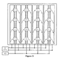
- the figure 3 illustrates a panel similar to the panel of the figure 2 , but whose mode of connection of the luminous devices is done in double parallel.
- the advantage of this mode of connection lies in the fact that all the LEDs are here placed in the same direction.
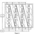
- figure 4 there is shown a symmetrical dual parallel connection. In this mode, all the LEDs are also placed in the same direction, but the intensity of the electric current flowing in the conductive tracks is two times lower than with the double parallel mounting of the figure 3 .
- connection in alternating parallel mode there is shown a connection in alternating parallel mode.
- the advantage here is to adapt the width of the conductive tracks to the intensity of the electric current flowing in the track.
- connection mode is still a serial mode, but with the LED's arranged in staggered rows.
- the conductive tracks have a shape better adapted to the current distribution.
- connection mode is serial-parallel and combines the advantages of serial and parallel connections.
Abstract
Description
La présente invention concerne un panneau d'affichage dont la résolution est adaptée à ses dimensions ainsi qu'à la distance optimale par rapport au panneau qu'un opérateur choisira pour une lecture confortable. Le panneau comprend des pixels lumineux pilotés par un système de contrôle.The present invention relates to a display panel whose resolution is adapted to its dimensions as well as to the optimal distance from the panel that an operator will choose for a comfortable reading. The panel comprises luminous pixels controlled by a control system.
Des panneaux d'affichage lumineux de grandes dimensions aptes à être accrochés sur la façade extérieure de bâtiments et pouvoir être lus de loin de manière confortable sont connus. Ils impliquent cependant un câblage d'alimentation et de pilotage des pixels relativement complexe, ce qui nuit généralement à la transparence de la totalité de la surface du panneau et à sa fiabilité à long terme en ce qui concerne le fonctionnement de tous les pixels du panneau. Généralement, une maintenance fréquente de ces panneaux connus est nécessaire et le coût peut rapidement en devenir assez important.Large illuminated billboards that can be hung on the exterior of buildings and can be read from a comfortable distance are known. However, they involve relatively complex pixel power and control wiring, which generally affects the transparency of the entire panel surface and its long-term reliability in the operation of all panel pixels. . Generally, frequent maintenance of these known panels is necessary and the cost can quickly become quite important.
L'invention remédie à ces inconvénients en fournissant un panneau d'affichage lumineux ne comportant pas de câblage apparent de chaque pixel et ne nécessitant qu'une maintenance réduite.The invention overcomes these disadvantages by providing a light display panel having no apparent cabling of each pixel and requiring only reduced maintenance.
A cet effet, l'invention concerne un panneau d'affichage lumineux tel que défini dans la revendication 1.For this purpose, the invention relates to a luminous display panel as defined in
Les revendications dépendantes définissent d'autres formes possibles de réalisation de l'invention, dont certaines sont préférées.
Outre la réduction des coûts déjà mentionnée, l'invention peut aussi apporter un ou plusieurs des avantages suivants :
- réalisation aisée d'une version transparente à la lumière visible;
- intégration possible dans un vitrage multiple;
- adaptation à la réalisation de façades de bâtiment entières communicantes.
In addition to the cost reduction already mentioned, the invention may also provide one or more of the following advantages:
- easy realization of a transparent version in visible light;
- possible integration in multiple glazing;
- adaptation to the realization of entire communicating building facades.
Le panneau d'affichage selon l'invention a une résolution adaptée à ses dimensions, c'est-à-dire qu'elle sera d'autant moins élevée que la taille du panneau sera grande et adaptée à une vision éloignée. Le panneau comprend des dispositifs lumineux qui constituent les pixels d'information. Ces dispositifs sont des sources de lumière blanche ou colorée apparaissant comme des points lumineux à la distance habituelle de lecture. Selon l'invention, l'allumage et l'extinction de ces sources lumineuses sont pilotées individuellement par un système de contrôle à structure hiérarchique. Par système de contrôle à structure hiérarchique, on désigne un système de commande et de contrôle comprenant des unités de contrôles interconnectées selon une topologie arborescente comprenant plusieurs niveaux, par exemple une unité de contrôle centrale ou générale connectée à un ensemble d'unités de contrôle locales, éventuellement via des unités de contrôle intermédiaire. Selon l'invention, l'intensité de chaque pixel peut aussi être pilotée par le même système de contrôle à structure hiérarchique.The display panel according to the invention has a resolution adapted to its dimensions, that is to say that it will be even lower than the size of the panel will be large and suitable for remote viewing. The panel includes light devices that constitute the information pixels. These devices are sources of white or colored light appearing as light points at the usual distance of reading. According to the invention, the lighting and extinction of these light sources are controlled individually by a hierarchical structure control system. Hierarchical structure control system means a control and control system comprising interconnected control units according to a tree topology comprising several levels, for example a central or general control unit connected to a set of local control units. possibly via intermediate control units. According to the invention, the intensity of each pixel can also be controlled by the same hierarchical structure control system.
Le panneau d'affichage conforme à l'invention se présente sous la forme d'un corps plat composite complètement fermé. Par corps plat, on entend désigner un solide dont l'épaisseur est faible par rapport à ses autres dimensions. Le panneau est un corps composite comprenant un substrat rigide sur lequel sont fixés les dispositifs lumineux. Par substrat rigide, on entend un corps, plat lui aussi, de résistance mécanique aux sollicitations de flexion et de torsion suffisante pour ne pas se déformer sous l'action de sollicitations extérieures que l'on rencontre couramment dans le milieu ambiant dans lequel on utilise généralement le panneau. En particulier, les substrats rigides utilisés résistent généralement bien au vent, et aux intempéries en général, que l'on rencontre dans les milieux d'utilisation de ces panneaux, y compris la glace et la neige. Des dispositifs lumineux sont fixés sur le substrat rigide et l'ensemble substrat plus dispositifs lumineux ainsi que tous les conducteurs électriques d'alimentation et de contrôle de ces derniers sont situés à l'intérieur du corps composite constituant le panneau d'affichage. Par ailleurs, selon l'invention, ces conducteurs électriques sont invisibles à l'oeil nu.The display panel according to the invention is in the form of a completely closed composite flat body. By flat body, we mean a solid whose thickness is small compared to its other dimensions. The panel is a composite body comprising a rigid substrate on which the light devices are fixed. Rigid substrate means a body, also flat, of mechanical resistance to bending and torsional stress sufficient not to deform under the action of external stresses that are commonly encountered in the ambient environment in which it is used usually the panel. In particular, the rigid substrates used generally withstand the wind, and bad weather in general, found in the environments where these panels are used, including ice and snow. Luminous devices are attached to the rigid substrate and the substrate assembly plus light devices as well as all electrical power supply and control conductors thereof are located at inside the composite body constituting the billboard. Moreover, according to the invention, these electrical conductors are invisible to the naked eye.
Un premier mode de réalisation préféré du panneau d'affichage conforme à l'invention est celui dans lequel le panneau est transparent à la lumière. Le plus souvent, la transparence du panneau est telle que le coefficient de transmission de la lumière à travers lui est maximum pour toutes les longueurs d'ondes appartenant au spectre de la lumière visible. Très fréquemment, le panneau est aussi capable de transmettre une proportion non négligeable des radiations lumineuses jouxtant immédiatement les longueurs d'onde du spectre visible, aussi bien en deçà qu'au-delà de celui-ci (lumières IR et UV).A first preferred embodiment of the display panel according to the invention is that in which the panel is transparent to light. Most often, the transparency of the panel is such that the transmission coefficient of light through it is maximum for all wavelengths belonging to the spectrum of visible light. Very frequently, the panel is also capable of transmitting a significant proportion of the light radiation immediately adjacent to the wavelengths of the visible spectrum, both below and beyond it (IR and UV lights).
Dans un autre mode de réalisation préféré du panneau d'affichage selon l'invention, compatible avec le précédent, le substrat rigide du corps composite constituant le panneau est du verre, éventuellement transparent. En variante, il est possible que l'ensemble du corps plat composite complètement fermé soit un vitrage feuilleté comprenant au moins une feuille de matière plastique laminée en sandwich entre deux feuilles de verre du corps composite. La matière plastique est choisie parmi celles qui sont habituellement utilisées pour les produits laminés, en particulier pour les verres laminés. En pratique, on peut choisir la matière plastique parmi les polyesters thermoplastiques, par exemple le polyvinylbutyral, les copolymères d'éthylène et d'acétate de vinyle et les polyéthylènetéréphtalates.In another preferred embodiment of the display panel according to the invention, compatible with the preceding, the rigid substrate of the composite body constituting the panel is glass, possibly transparent. Alternatively, it is possible that the entire closed flat composite body is a laminated glazing comprising at least one laminated plastic sheet sandwiched between two glass sheets of the composite body. The plastic is selected from those usually used for rolled products, particularly for laminated glass. In practice, the plastic may be selected from thermoplastic polyesters, for example polyvinyl butyral, copolymers of ethylene and vinyl acetate and polyethylene terephthalates.
Particulièrement préférés sont les panneaux d'affichage dont le corps plat composite complètement fermé est un vitrage multiple, et le plus souvent, un vitrage double traditionnel à propriétés d'isolation thermique. Dans ce mode de réalisation, les dispositifs lumineux sont fixés de préférence sur la surface intérieure d'une des vitres du vitrage multiple, dans un espace entre deux des vitres. Une des vitres du vitrage multiple peut être constituée par une structure feuilletée comprenant une matière plastique, comme exposé plus haut.Particularly preferred are the billboards whose closed flat composite body is a multiple glazing, and usually a traditional double glazing with thermal insulation properties. In this embodiment, the light devices are preferably fixed on the inner surface of one of the panes of the multiple glazing, in a space between two panes. One of the windows of the multiple glazing may be constituted by a laminated structure comprising a plastic material, as explained above.
Un autre mode de réalisation du panneau d'affichage selon l'invention, compatible avec tous les modes exposés jusqu'ici, est celui dans lequel les dispositifs lumineux sont choisis parmi les lampes à incandescence de filament, les lampes à vapeur d'halogène, à vapeur de métal alcalin ou alcalino-terreux, à vapeur de mercure, les lampes à décharge dans un gaz, telles que les lampes au néon ou au xénon, les composants électroniques solides semi-conducteurs, tels que les diodes électroluminescentes ("LED's"), y compris les diodes électroluminescentes organiques ("OLED's"). Les diodes électroluminescentes sont préférées en raison de leur compacité, de leur faible dégagement calorifique et de leur plus grande facilité de montage. Chaque pixel peut comprendre plusieurs dispositifs lumineux disposés côte à côte. En particulier, chaque pixel peut être composé de trois LED's colorées capables d'émettre chacune un rayonnement coloré monochromatique du spectre visible. Avantageusement, on choisit les couleurs des trois LED's d'un pixel comme rouge, jaune et bleue, de manière à pouvoir générer par leur mélange en diverses proportions ou intensité de courant électrique d'alimentation, toute couleur du spectre visible.Another embodiment of the display panel according to the invention, compatible with all the modes exposed so far, is the one in which the luminous devices are chosen from filament filament lamps, halogen vapor lamps, alkali or alkaline earth metal vapor, mercury vapor, gas discharge lamps, such as neon or xenon lamps, semiconductor solid electronic components, such as light emitting diodes ("LEDs") ), including organic light-emitting diodes ("OLED's"). Light-emitting diodes are preferred because of their compactness, low heat output and ease of assembly. Each pixel may comprise several light devices arranged side by side. In particular, each pixel may be composed of three colored LEDs each capable of emitting a monochromatic colored radiation of the visible spectrum. Advantageously, the colors of the three LEDs of a pixel are chosen as red, yellow and blue, so as to be able to generate by their mixture in various proportions or intensity of electrical power supply, any color of the visible spectrum.
Lorsque le panneau d'affichage comprend des dispositifs lumineux sous forme de LED's, il est avantageux que les LED's soient laminées à l'interface d'au moins une feuille de verre et d'une feuille de matière plastique. Avantageusement, les LED's sont laminées avec la matière plastique de manière telle qu'elles se situent complètement à l'intérieur de la feuille de cette matière qui est choisie avec une épaisseur d'au moins 10 % supérieure à celle des diodes et pouvant aller jusqu'à 50 % supérieure à celle des diodes. En cas de feuille de matière plastique d'épaisseur insuffisante, il est possible de laminer ensemble un empilage de plusieurs de ces feuilles de manière à dépasser d'au moins 10 % l'épaisseur des LED's.When the display panel comprises luminous devices in the form of LED's, it is advantageous for the LEDs to be laminated at the interface of at least one glass sheet and one plastic sheet. Advantageously, the LEDs are laminated with the plastic material in such a way that they lie completely inside the sheet of this material which is chosen with a thickness of at least 10% greater than that of the diodes and which can go up to 50% higher than that of the diodes. In case of plastic sheet of insufficient thickness, it is possible to roll together a stack of several of these sheets so as to exceed by at least 10% the thickness of the LED's.
Un autre mode de réalisation compatible aussi avec les modes précédents consiste à alimenter les LED's en énergie électrique via un réseau de fils conducteurs laminés dans la matière plastique ou sérigraphiés sur la face intérieure d'une feuille de verre laminé. Alternativement, les LED's peuvent aussi être alimentées via une couche électro conductrice transparente recouvrant la feuille de verre sur laquelle elles reposent, à l'interface de celle-ci avec la matière plastique. Des pistes formant des chemins de courant d'alimentation des LED's peuvent avoir été découpées dans cette couche conductrice par l'action d'un rayon laser qui brûle la couche sur une faible largeur, réalisant ainsi des sillons non conducteurs qui délimitent les pistes dans le reste de la couche.Another embodiment also compatible with the preceding modes is to supply the LEDs with electrical energy via a network of conductive wires laminated in the plastic or screen printed on the inner face of a laminated glass sheet. Alternatively, the LEDs can also be fed via a transparent electroconductive layer covering the glass sheet on which they rest, at the interface thereof with the plastic material. Tracks forming power supply paths of the LEDs may have been cut in this conductive layer by the action of a laser beam which burns the layer over a narrow width, thereby forming non-conductive grooves which delimit the tracks in the rest of the layer.
Le panneau d'affichage selon l'invention peut aussi constituer un sous ensemble d'éléments architecturaux d'une ou plusieurs parois d'un bâtiment, en particulier une paroi extérieure. De manière préférée, les éléments architecturaux sont des vitrages de fenêtres et/ou des allèges recouvrant des façades de bâtiment.The display panel according to the invention may also constitute a subset of architectural elements of one or more walls of a building, in particular an outer wall. Preferably, the architectural elements are window panes and / or spandrels covering building facades.
Dans un autre mode de réalisation de l'invention, compatible aussi avec les précédents, le système de contrôle à structure hiérarchique se compose d'une unité de contrôle général et d'une multitude de microcontrôleurs associés chacun à un pixel individuel. L'unité de contrôle général peut être un automate programmable ou un ordinateur de contrôle de procédés, dédiés exclusivement au contrôle d'un ou de plusieurs panneaux conformes à l'invention. Alternativement, l'unité de contrôle général peut gérer les panneaux selon l'invention simultanément à d'autres commandes et régulations de processus, par exemple des processus liés à des applications domotiques du bâtiment concerné. Les microcontrôleurs associés aux pixels individuels sont de préférence des composants électroniques disposés au contact du dispositif lumineux qu'ils contrôlent. Avantageusement, ils sont disposés derrière le dispositif lumineux, en particulier derrière chaque LED monochromatique ou encore derrière chaque trio de LED's colorées. Des unités de contrôle intermédiaires peuvent parfois être disposées dans la structure arborescente, entre le niveau central général et les microcontrôleurs de pixel, par exemple une unité intermédiaire s'adressant à un vitrage de fenêtre ou un étage de façade du bâtiment.In another embodiment of the invention, also compatible with the above, the hierarchical structure control system consists of a general control unit and a multitude of microcontrollers each associated with an individual pixel. The general control unit may be a programmable logic controller or a process control computer, dedicated exclusively to controlling one or more panels according to the invention. Alternatively, the general control unit can manage the panels according to the invention simultaneously with other commands and process controls, for example processes related to home automation applications of the building concerned. The microcontrollers associated with the individual pixels are preferably electronic components arranged in contact with the light device they control. Advantageously, they are arranged behind the luminous device, in particular behind each monochromatic LED or behind each trio of colored LEDs. Intermediate control units can sometimes be arranged in the tree structure, between the general central level and the pixel microcontrollers, for example an intermediate unit addressing a window glazing or a building facade floor.
Selon l'invention, la communication entre l'unité de contrôle général et les unités de contrôle intermédiaire s'effectue par le canal d'un moyen de communication informatique traditionnel. De même, la communication entre les unités de contrôle intermédiaire et les microcontrôleurs de pixel peut, par exemple, s'effectuer via un réseau filaire dont les canaux d'information sont matérialisés par les conducteurs électriques de contrôle situés à l'intérieur du panneau. Alternativement, ce réseau peut aussi être constitué par des pistes découpées dans la couche conductrice transparente. En variante, cette communication entre les unités de contrôle intermédiaire et les microcontrôleurs de pixel peut encore s'effectuer via un réseau sans fil. De préférence, le réseau sans fil utilise le canal des ondes radio, par exemple un réseau selon un des standards, bien connus par eux-mêmes dans le domaine de traitement de l'information, comme ceux dénommés "Bluetooth" ou encore "Wi-Fi".According to the invention, the communication between the general control unit and the intermediate control units is effected by means of a traditional computer communication means. Similarly, the communication between the intermediate control units and the pixel microcontrollers can, for example, be carried out via a wired network whose information channels are materialized by the electrical control conductors located inside the panel. Alternatively, this network may also consist of tracks cut in the transparent conductive layer. Alternatively, this communication between the intermediate control units and the pixel microcontrollers can still be performed via a wireless network. Preferably, the wireless network uses the radio wave channel, for example a network according to one of the standards, which are well-known in the field of information processing, such as those referred to as "Bluetooth" or "Wi-Fi". Fi. "
L'invention est illustrée de manière plus détaillée dans les exemples qui suivent en faisant référence aux planches de dessins dans lesquelles :
- les
figures 1a et 1b schématisent une vue en coupe d'éléments architecturaux formés de doubles vitrages selon deux modes de réalisation différents. Seule une partie de ces éléments est représentée; - les
figures 2 à 8 illustrent le principe de modes de connexion de LED's via des pistes conductrices transparentes.
- the
Figures 1a and 1b schematically a sectional view of architectural elements formed of double glazing according to two different embodiments. Only a part of these elements is represented; - the
Figures 2 to 8 illustrate the principle of LED's connection modes via transparent conductive tracks.
Aux
A la
A la
La
La
De même, à la
A la
A la
A la
Enfin, à la
Claims (20)
Priority Applications (4)
| Application Number | Priority Date | Filing Date | Title |
|---|---|---|---|
| EP06126382A EP1956580A1 (en) | 2006-12-18 | 2006-12-18 | Display panel |
| EA200900844A EA016383B1 (en) | 2006-12-18 | 2007-12-18 | Display panel |
| EP07857759A EP2104931A1 (en) | 2006-12-18 | 2007-12-18 | Display panel |
| PCT/EP2007/064134 WO2008074800A1 (en) | 2006-12-18 | 2007-12-18 | Display panel |
Applications Claiming Priority (1)
| Application Number | Priority Date | Filing Date | Title |
|---|---|---|---|
| EP06126382A EP1956580A1 (en) | 2006-12-18 | 2006-12-18 | Display panel |
Publications (1)
| Publication Number | Publication Date |
|---|---|
| EP1956580A1 true EP1956580A1 (en) | 2008-08-13 |
Family
ID=38006876
Family Applications (2)
| Application Number | Title | Priority Date | Filing Date |
|---|---|---|---|
| EP06126382A Withdrawn EP1956580A1 (en) | 2006-12-18 | 2006-12-18 | Display panel |
| EP07857759A Withdrawn EP2104931A1 (en) | 2006-12-18 | 2007-12-18 | Display panel |
Family Applications After (1)
| Application Number | Title | Priority Date | Filing Date |
|---|---|---|---|
| EP07857759A Withdrawn EP2104931A1 (en) | 2006-12-18 | 2007-12-18 | Display panel |
Country Status (3)
| Country | Link |
|---|---|
| EP (2) | EP1956580A1 (en) |
| EA (1) | EA016383B1 (en) |
| WO (1) | WO2008074800A1 (en) |
Cited By (2)
| Publication number | Priority date | Publication date | Assignee | Title |
|---|---|---|---|---|
| EP2110806A3 (en) * | 2008-01-30 | 2010-09-15 | Jaro Kapus | Earmarked display with intelligent light points |
| WO2011101354A1 (en) * | 2010-02-16 | 2011-08-25 | Agc Glass Europe | Panel having an improved conductive pattern |
Families Citing this family (16)
| Publication number | Priority date | Publication date | Assignee | Title |
|---|---|---|---|---|
| DE102008052806A1 (en) * | 2008-10-22 | 2010-04-29 | Reinhard Cordes | insulating glass pane |
| WO2010088958A1 (en) * | 2009-02-06 | 2010-08-12 | Agc Glass Europe | Electronic array comprising at least two dimensions |
| WO2010088961A1 (en) * | 2009-02-06 | 2010-08-12 | Agc Glass Europe | Electronic array comprising a plurality of electronic units |
| DE102009053465A1 (en) * | 2009-11-16 | 2011-05-19 | Inglas Innovative Glassysteme Gmbh & Co. Kg | Function disk for reproduction of stationary and moving pictures, comprises a component of two disks made of glasses or plastics, and functional elements introduced in the component |
| FR2953631B1 (en) * | 2009-12-08 | 2012-02-24 | Citiled | DEVICE FOR DISPLAYING A VIDEO IMAGE ON AN EDIFICE PROVIDED WITH MULTIPLE WINDOWS |
| FR2953633B1 (en) * | 2009-12-08 | 2015-12-11 | Citiled | ELEMENT IN PARTICULAR FOR FACADE COMPRISING A GLASS AND LIGHT-EMITTING DIODES |
| FR2953632B1 (en) * | 2009-12-08 | 2015-12-11 | Citiled | LIGHT EMITTING DIODE DISPLAY COMPRISING CONNECTION MEANS |
| PT105413A (en) | 2010-11-30 | 2012-07-27 | Vidraria Central De Ermesinde Lda | GLASS ILLUMINATED AND INSULATED WITH LEDS |
| DE202011105583U1 (en) | 2011-09-12 | 2011-12-05 | Hema Maschinen- Und Apparateschutz Gmbh | Cover with safety disc |
| LV14991B (en) | 2013-10-04 | 2015-06-20 | Palami, Sia | Light emitting module and system of modules |
| GB2519587A (en) * | 2013-10-28 | 2015-04-29 | Barco Nv | Tiled Display and method for assembling same |
| RU169589U1 (en) * | 2016-06-01 | 2017-03-23 | Общество с ограниченной ответственностью "Эй Джи Си Флэт Гласс Клин" | STAND FOR DEMONSTRATION OF GLASSES |
| FR3065116B1 (en) * | 2017-04-05 | 2021-08-27 | Commissariat Energie Atomique | LED TRANSMITTED IMAGE DISPLAY DEVICE |
| FR3065117B1 (en) | 2017-04-05 | 2019-07-05 | Commissariat A L'energie Atomique Et Aux Energies Alternatives | IMAGE EMISSIF IMAGE DISPLAY DEVICE |
| KR102577090B1 (en) | 2018-01-26 | 2023-09-12 | 엘지전자 주식회사 | Lamp using semiconductor light emitting device and method for manufacturing the same |
| DE102018107309B4 (en) * | 2018-03-27 | 2019-10-10 | Symonics GmbH | Transparent display device |
Citations (6)
| Publication number | Priority date | Publication date | Assignee | Title |
|---|---|---|---|---|
| WO2001082378A1 (en) * | 2000-04-20 | 2001-11-01 | Schott Glas | Carrier substrate for electronic components |
| GB2362022A (en) * | 2000-03-16 | 2001-11-07 | Beverley Mildred Graham | Double skinned illuminated sign |
| WO2004017434A2 (en) * | 2002-08-06 | 2004-02-26 | E.I. Du Pont De Nemours And Company | Laminated polymer with integrated lighting, sensors and electronics |
| WO2004062908A2 (en) * | 2003-01-10 | 2004-07-29 | Glaverbel | Glazing comprising electronic elements |
| US20050233125A1 (en) * | 2002-08-06 | 2005-10-20 | Christopher Anderson | Laminated glass and structural glass with integrated lighting, sensors and electronics |
| EP1715521A1 (en) * | 2005-04-21 | 2006-10-25 | C.R.F. Società Consortile per Azioni | Method for manufacture of transparent devices having light emitting diodes (LED) |
Family Cites Families (1)
| Publication number | Priority date | Publication date | Assignee | Title |
|---|---|---|---|---|
| US5767818A (en) * | 1994-09-27 | 1998-06-16 | Nishida; Shinsuke | Display device |
-
2006
- 2006-12-18 EP EP06126382A patent/EP1956580A1/en not_active Withdrawn
-
2007
- 2007-12-18 EP EP07857759A patent/EP2104931A1/en not_active Withdrawn
- 2007-12-18 WO PCT/EP2007/064134 patent/WO2008074800A1/en active Application Filing
- 2007-12-18 EA EA200900844A patent/EA016383B1/en not_active IP Right Cessation
Patent Citations (6)
| Publication number | Priority date | Publication date | Assignee | Title |
|---|---|---|---|---|
| GB2362022A (en) * | 2000-03-16 | 2001-11-07 | Beverley Mildred Graham | Double skinned illuminated sign |
| WO2001082378A1 (en) * | 2000-04-20 | 2001-11-01 | Schott Glas | Carrier substrate for electronic components |
| WO2004017434A2 (en) * | 2002-08-06 | 2004-02-26 | E.I. Du Pont De Nemours And Company | Laminated polymer with integrated lighting, sensors and electronics |
| US20050233125A1 (en) * | 2002-08-06 | 2005-10-20 | Christopher Anderson | Laminated glass and structural glass with integrated lighting, sensors and electronics |
| WO2004062908A2 (en) * | 2003-01-10 | 2004-07-29 | Glaverbel | Glazing comprising electronic elements |
| EP1715521A1 (en) * | 2005-04-21 | 2006-10-25 | C.R.F. Società Consortile per Azioni | Method for manufacture of transparent devices having light emitting diodes (LED) |
Cited By (4)
| Publication number | Priority date | Publication date | Assignee | Title |
|---|---|---|---|---|
| EP2110806A3 (en) * | 2008-01-30 | 2010-09-15 | Jaro Kapus | Earmarked display with intelligent light points |
| WO2011101354A1 (en) * | 2010-02-16 | 2011-08-25 | Agc Glass Europe | Panel having an improved conductive pattern |
| BE1019185A3 (en) * | 2010-02-16 | 2012-04-03 | Agc Glass Europe | PANEL WITH IMPROVED CONDUCTIVE PATTERN. |
| EA023566B1 (en) * | 2010-02-16 | 2016-06-30 | Агк Гласс Юроп | Optically transparent laminated panel |
Also Published As
| Publication number | Publication date |
|---|---|
| WO2008074800A1 (en) | 2008-06-26 |
| EA200900844A1 (en) | 2009-12-30 |
| EA016383B1 (en) | 2012-04-30 |
| EP2104931A1 (en) | 2009-09-30 |
Similar Documents
| Publication | Publication Date | Title |
|---|---|---|
| EP1956580A1 (en) | Display panel | |
| EP2665601B1 (en) | Luminous glass panel | |
| EP2005226B1 (en) | Luminous panel | |
| EP1969403B1 (en) | Luminous structure comprising at least one light-emitting diode, its manufacture and its applications | |
| FR2892594A1 (en) | LIGHT STRUCTURE COMPRISING AT LEAST ONE ELECTROLUMINESCENT DIODE, ITS MANUFACTURE AND ITS APPLICATIONS | |
| EP2861421B1 (en) | Vitrous roof endowed with lighting devices | |
| BE1021369B1 (en) | VEHICLE ROOF GLASS | |
| WO2014009630A1 (en) | Luminous glass panel | |
| US20050233125A1 (en) | Laminated glass and structural glass with integrated lighting, sensors and electronics | |
| EP1437215A1 (en) | Glazing comprising a luminous element | |
| EP0575207A1 (en) | Architeral electrochromic glazing | |
| CA3025132A1 (en) | Illuminated laminated sunroof for vehicle, vehicle incorporating same, and manufacture | |
| FR2932307A1 (en) | DEVICE FOR DISPLAYING A VIDEO IMAGE ON AN EDIFICE | |
| WO2013167270A1 (en) | Organic photonic device | |
| EP2134541A1 (en) | Method for the power supply of an electronic component in a laminated glazing, laminated glazing implementing said method, and equipment including a laminated glazing | |
| CA2598211A1 (en) | Planar or substantially planar luminous structure | |
| EP1932813A1 (en) | Transparent illuminated panel | |
| EP0368707B1 (en) | Heated multiglazed window | |
| CN107690387B (en) | Method for providing electrical power to electronic components of a laminated glazing unit and laminated glazing unit for carrying out said method | |
| WO2011070287A1 (en) | Element, especially for a building façade, comprising a glass pane and light-emitting diodes | |
| WO2020020773A1 (en) | Enamelled substrate, illuminated glazed device comprising such a substrate, and production thereof | |
| WO2011070286A1 (en) | Device for displaying a video image on an edifice fitted with several glazing panels | |
| FR2983620A1 (en) | Base element e.g. French window, for video image display device used on e.g. outer front wall of building, has LEDs to emit light via front pane, where zone of rear surface of pane located against LEDs is free from photovoltaic element |
Legal Events
| Date | Code | Title | Description |
|---|---|---|---|
| PUAI | Public reference made under article 153(3) epc to a published international application that has entered the european phase |
Free format text: ORIGINAL CODE: 0009012 |
|
| AK | Designated contracting states |
Kind code of ref document: A1 Designated state(s): AT BE BG CH CY CZ DE DK EE ES FI FR GB GR HU IE IS IT LI LT LU LV MC NL PL PT RO SE SI SK TR |
|
| AX | Request for extension of the european patent |
Extension state: AL BA HR MK RS |
|
| 17P | Request for examination filed |
Effective date: 20090213 |
|
| STAA | Information on the status of an ep patent application or granted ep patent |
Free format text: STATUS: THE APPLICATION HAS BEEN WITHDRAWN |
|
| 17Q | First examination report despatched |
Effective date: 20090316 |
|
| AKX | Designation fees paid |
Designated state(s): AT BE BG CH CY CZ DE DK EE ES FI FR GB GR HU IE IS IT LI LT LU LV MC NL PL PT RO SE SI SK TR |
|
| 18W | Application withdrawn |
Effective date: 20090324 |