EP1956571B1 - Tire pressure monitor device - Google Patents
Tire pressure monitor device Download PDFInfo
- Publication number
- EP1956571B1 EP1956571B1 EP06833495A EP06833495A EP1956571B1 EP 1956571 B1 EP1956571 B1 EP 1956571B1 EP 06833495 A EP06833495 A EP 06833495A EP 06833495 A EP06833495 A EP 06833495A EP 1956571 B1 EP1956571 B1 EP 1956571B1
- Authority
- EP
- European Patent Office
- Prior art keywords
- wheel
- data
- antenna
- sensor units
- tire pressure
- Prior art date
- Legal status (The legal status is an assumption and is not a legal conclusion. Google has not performed a legal analysis and makes no representation as to the accuracy of the status listed.)
- Expired - Fee Related
Links
Images


Classifications
-
- B—PERFORMING OPERATIONS; TRANSPORTING
- B60—VEHICLES IN GENERAL
- B60C—VEHICLE TYRES; TYRE INFLATION; TYRE CHANGING; CONNECTING VALVES TO INFLATABLE ELASTIC BODIES IN GENERAL; DEVICES OR ARRANGEMENTS RELATED TO TYRES
- B60C23/00—Devices for measuring, signalling, controlling, or distributing tyre pressure or temperature, specially adapted for mounting on vehicles; Arrangement of tyre inflating devices on vehicles, e.g. of pumps or of tanks; Tyre cooling arrangements
- B60C23/02—Signalling devices actuated by tyre pressure
- B60C23/04—Signalling devices actuated by tyre pressure mounted on the wheel or tyre
- B60C23/0408—Signalling devices actuated by tyre pressure mounted on the wheel or tyre transmitting the signals by non-mechanical means from the wheel or tyre to a vehicle body mounted receiver
- B60C23/0415—Automatically identifying wheel mounted units, e.g. after replacement or exchange of wheels
- B60C23/0416—Automatically identifying wheel mounted units, e.g. after replacement or exchange of wheels allocating a corresponding wheel position on vehicle, e.g. front/left or rear/right
-
- B—PERFORMING OPERATIONS; TRANSPORTING
- B60—VEHICLES IN GENERAL
- B60C—VEHICLE TYRES; TYRE INFLATION; TYRE CHANGING; CONNECTING VALVES TO INFLATABLE ELASTIC BODIES IN GENERAL; DEVICES OR ARRANGEMENTS RELATED TO TYRES
- B60C23/00—Devices for measuring, signalling, controlling, or distributing tyre pressure or temperature, specially adapted for mounting on vehicles; Arrangement of tyre inflating devices on vehicles, e.g. of pumps or of tanks; Tyre cooling arrangements
- B60C23/02—Signalling devices actuated by tyre pressure
- B60C23/04—Signalling devices actuated by tyre pressure mounted on the wheel or tyre
- B60C23/0408—Signalling devices actuated by tyre pressure mounted on the wheel or tyre transmitting the signals by non-mechanical means from the wheel or tyre to a vehicle body mounted receiver
- B60C23/0422—Signalling devices actuated by tyre pressure mounted on the wheel or tyre transmitting the signals by non-mechanical means from the wheel or tyre to a vehicle body mounted receiver characterised by the type of signal transmission means
- B60C23/0433—Radio signals
- B60C23/0435—Vehicle body mounted circuits, e.g. transceiver or antenna fixed to central console, door, roof, mirror or fender
- B60C23/0444—Antenna structures, control or arrangements thereof, e.g. for directional antennas, diversity antenna, antenna multiplexing or antennas integrated in fenders
Landscapes
- Engineering & Computer Science (AREA)
- Mechanical Engineering (AREA)
- Arrangements For Transmission Of Measured Signals (AREA)
- Measuring Fluid Pressure (AREA)
Description
- The present invention belongs to a technical field in which a tire pressure monitoring device that receives tire pressure signals wirelessly transmitted from sensor units provided on tires of a motor vehicle and judges positions of the tires with the sensor units based on received signal levels, to monitor tire pressures in relation of respective positions of the tires.
- In a conventional tire pressure monitoring device, it receives without wire information on rotational directions of tires outputted from detecting units provided on all the tires, and detects an installation position of each tire based on the rotational direction of the tire, obtained from the rotational direction information, and receiver sensitivity of received wireless signals. Such a device is disclosed in Japanese Patents Laid-open No.
2005 - 112056 DE 10305373 .EP 1215056 also discloses a tire pressure monitoring device. Its features are set out in the preamble ofclaim 1 appended hereto. - However, in the conventional monitoring device, there happens to be a case where a plurality of transmitting apparatuses of the detecting units sends the pressure signals at the same time. The same timings of transmissions cause collisions of data, and consequently the monitoring device cannot receive both or all data, thereby causing a lack in data.
- The present invention is made in order to solve the above described problem, and its object is to provide a tire pressure monitoring device which can surely receive data so as to decrease a lack in the data, thereby obtaining a high reliability thereof.
- In order to achieve the above object, a tire pressure monitoring device as defined in
claim 1 is provided. The device of the invention is constructed to include sensor units provided on respective wheels of a motor vehicle, and a receiving apparatus which is provided on a vehicle body of the motor vehicle and receives data signals of tire pressures wirelessly sent at substantially the same output levels from the sensor units. The receiving apparatus includes at least two receiving antennas located apart from each other in a longitudinal direction of the motor vehicle, an antenna shifting means for shifting or moving the receiving antennas, a reception intensity level detecting means for detecting reception intensity levels of the received data signals outputted from the sensor units, a front-wheel/rear wheel judging means for judging, based on the reception intensity level, whether the wheel, provided with the sensor unit from which the data signal is received, is a front wheel or a rear wheel,
a signal collision estimating means for estimating whether the data signal from the sensor unit of the front wheel and the data signal from the sensor unit of the rear wheel collide with each other, and a shifting control means for actuating the antenna shifting means so that the reception intensity levels depart from each other when the data signal from the sensor unit of the front wheel and the data signal from the sensor unit of the rear wheel collide with each other. - Therefore, the tire pressure monitoring device of the invention can more surely receive the data to decrease the lack in the data, thereby increasing its reliability.
-
-
FIG. 1 is a schematic view showing a construction of a motor vehicle which is provided with a tire pressure monitoring device of a first embodiment according to the present invention; -
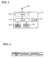
FIG 2 is a control block diagram showing a receiving apparatus which used for the tire pressure monitoring device, mounted on a vehicle body, of the first embodiment; -
FIG. 3 is a control block diagram showing a sensor unit provided on a wheel side of the first embodiment; -
FIG 4 is a diagram explaining information included in transmission data outputted from the sensor unit of the first embodiment; -
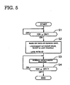
FIG 5 is a flow chart showing a flow of a tire pressure monitoring process which contains a tire position detecting process executed by the receiving apparatus of the first embodiment; -
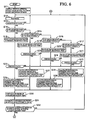
FIG 6 is a flow chart showing a part of a flow of a receiving process in the tire pressure monitoring process executed by the receiving apparatus of the first embodiment; -
FIG 7 is a flow chart showing the rest of the flow of the receiving process in the tire pressure monitoring executed by the receiving apparatus of the first embodiment; -
FIG 8 is a diagram explaining a state where a data signal, outputted from the sensor unit provided on a front wheel, and a data signal, outputted from the sensor unit provided a rear wheel, always collide with each other in the tire pressure monitoring device of the first embodiment; -
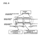
FIG 9 is a diagram explaining a state where the data signal, outputted from the sensor unit provided on the front wheel, and the data signal, outputted from the sensor unit provided the rear wheel, collide with each other only at certain time in the tire pressure monitoring device of the first embodiment; -
FIG 10 is a graph showing results of a measurement of receiving sensitivity in a case where a built-in antenna receives the signals outputted from the sensor units of the front and rear wheels in the tire pressure monitoring device of the first embodiment; and -
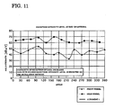
FIG 11 is a graph showing results of a measurement of the receiving sensitivity in a case where an external antenna receives the signals outputted from the sensor units of the front and rear wheels in the tire pressure monitoring device of the first embodiment. -
- 1
- receiving apparatus
- 11
- CPU part
- 12
- tuner
- 13
- antenna shifting part
- 14
- regulator
- 15
- I/O interface
- 16
- built-in antenna (receiving antenna)
- 17
- external antenna (receiving antenna)
- 2 (2a to 2d)
- sensor unit
- 21
- CPU part
- 22
- tire pressure sensor
- 23
- rotation sensor
- 24
- battery
- 25
- RF part
- 26
- antenna
- 3 (3a to 3d)
- tire
- Hereinafter, the embodiment of the invention for realizing a tire pressure monitoring device will be described with reference to the accompanying drawings.
- Firstly, a construction of the tire pressure monitoring device of a first embodiment will be described.
FIG 1 is a view showing a construction of a tire pressure monitoring system of the first embodiment.
The tire pressure monitoring system TPMS mainly includes a receivingapparatus 1 provided on a vehicle body of a motor vehicle, and sensor units 2 (2a to 2d) provided on fourtires 3a to 3d, respectively.
FIG 2 is a control block diagram showing the receivingapparatus 1 in the tire pressure monitoring device of the first embodiment. - The receiving
apparatus 1 mainly consists of a Central Processing Unit (CPU)part 11, atuner 12, anantenna shifting part 13, aregulator 14, an Input/Output (I/O)interface 15, a built-in antenna and anexternal antenna 17.
TheCPU part 11 executes antenna shifting control, communication of data between the receivingapparatus 1 and on-vehicle device (or vehicle communication network), identification of identification numbers outputted from thesensor units 2, judgment in determining a left wheel or a right wheel based on information on rotational directions of the wheels, a judgment in determining a front wheel or a rear wheel based on receiving sensitivities and others, and it sends information on states of the wheels. Thetuner 12 converts a received radio signal to output to theCPU part 11. Theantenna shifting part 13 shifts between the built-inantenna 16 and theexternal antenna 17. Theantenna shifting part 13 corresponds to an antenna shifting means of the present invention. - The
regulator 14 supplies its electric power to theCPU part 11 and thetuner 12.
The I/O interface 16 is built in the receivingapparatus 1, and it is arranged at a front side in the interior of a passenger room.
Theexternal antenna 17 is provided at a rear side at the exterior of the passenger room, and it also functions as a receiving antenna of a keyless entry system. It is preferable that theexternal antenna 17 is arranged at an outer side of a vehicle external body, for example in a bumper. -
FIG. 3 is a control block diagram of the sensor units in the first embodiment.
Eachsensor unit 2 mainly consists of aCPU part 21, atire pressure sensor 22, arotation sensor 23, abattery 24, a Radio Frequency (RF)part 25 and anantenna 26.
TheCPU part 21 stores respective information on identification numbers therein, then producing data shown inFIG 4 to execute a process and its control for sending the data to the receivingapparatus 1.
Thetire pressure sensor 22 detects a pressure of a tire provided therewith. Therotation sensor 23 detects a rotational direction of the tire provided therewith. As therotation sensor 23, an acceleration sensor is employed for example.
Thebattery 24 supplies its electric power to necessary parts of thesensor units 2.
TheRF part 25 converts the data shown inFIG 4 outputted from theCPU part 21 into a radio signal, and then it outputs it as an RF wave from theantenna 26. - Next, the operation of the tire pressure monitoring device of the first embodiment will be described.
- In the tire pressure monitoring system TPMS, the
sensor units 2 of the tire position detecting device detect stops/rotations of the tires by using therotation sensors 23, respectively. Further, thesensor units 2 change data transmission periods based on the stops/rotations of the tires.
A tire stop period is set to be relatively long, for example one hour, while a tire rotation period is set to be relatively shot, for example ten seconds or one minute. - Starts of the transmission of the data are judged by the
sensor units 2, respectively, which may cause the transmission timings to become the same between thesensor units 2 in some cases.
In that case, thesensor units 2 are constructed so that at least two frames can be avoided from the collision of data, by sending the same data by some frames in one transmission, and also by setting intermission time between transmissions of the frames to be varied. The data is fixed when the received two frames are completely consistent with each other, while inconsistent data is judged to be erroneous data.
However, two frames are not always received according to a surrounding environment and others. The motor vehicle is provided with the foursensor units 2, which independently send the data at their own timings. This sometime causes the transmission timings of the plurality of sensor units to be the same time, consequently causing the collision of data. In this case, their data cannot be received by the receivingapparatus 1.
The tire pressure monitoring device of the present invention solves the problemas described above. -
FIG 5 is a flow chart showing a flow of a tire pressure monitoring process, including a tire position detecting process, executed by the receivingapparatus 1 of the first embodiment, and hereinafter each step thereof will be described. - At a step S1, the
CPU part 11 judges whether or not an ignition (IGN) electric power source is ON. If the IGN is ON, the flow goes to a step S2, while if the IGN is OFF, the flow returns to the step S1. - At the step S2, the
CPU part 11 receives information from eachsensor unit 2, and then it judges based on information on the rotation directions of the tires on which side wheel (the left wheel or the right wheel) the sensor units are provided in relation to each ID( namely identification information). In addition, it also judges, based on the receiving sensitivity of theexternal antenna 17, on which side wheel( the front wheel or the rear wheel) the sensor units are provided in relation to the identification information. This step S2 corresponds to a front wheel-a rear wheel judging means of the present invention.
Further, the identification information and data on tire pressures are linked with the positions of the tires, to be stored. - At a step S3, the tire pressure monitoring device executes a normal tire pressure monitoring process. In this process, the positions of the tires and the data on the tire pressures are always linked with each other.
- At a step S4, the
CPU part 11 judges whether or not the IGN electric power source is OFF. If it is OFF, the flow ends, while if it is ON, the flow returns to the step S3. -
FIG 6 andFIG 7 is a flow chart showing a flow of a receiving process in the tire pressure monitoring process executed by the receivingapparatus 1 of the first embodiment, and hereinafter each step thereof will be described. Incidentally, in the ID data, A indicates a rear right wheel, B indicates a rear left wheel, C indicates a front right wheel and D indicates a front left wheel. - At a step S11, the receiving
apparatus 1 starts a timer in a state where it uses the built-inantenna 16, and also it starts the data reception, and then the flow goes to a step S12. - At the step S12, it waits to receive the data, and then the flow goes to a step S13.
- At the step S13, it judges whether or not the data is received. If the data is received, the flow goes to a
step S 14, whole if the data is not received, the flow returns to the step S12. - At the step S14, it judges whether or not the received ID data indicates "A (the rear right wheel)". If it indicates A, the flow goes to a step S18, while if it dos not indicate A, the flow goes to a step S15.
- At the step S15, it judges whether or not the received ID data indicates "B (the rear left wheel)". If it indicates B, the flow goes to a step S19, while if it dos not indicate B, the flow goes to a step S16.
- At the step S16, it judges whether or not the received ID data indicates "C (the front right wheel)". If it indicates C, the flow goes to a step S20, while if it dos not indicate C, the flow goes to a step S17.
- At the step S17, it judges whether or not the received ID data indicates "D (the front left wheel)". If it indicates D, the flow goes to a step S21, while if it does not indicate D, the flow returns to the step S12.
- At the step S18, the ID data and receipt time are stored as receipt contents, and then the flow goes to a step S22.
- At the step S19, the ID data and receipt time are stored as receipt contents, and then the flow goes to a step S23.
- At the step S20, the ID data and receipt time are stored as receipt contents, and then the flow goes to a step S24.
- At the step S21, the ID data and receipt time are stored as receipt contents, and then the flow goes to a step S25.
- At the step S22, it judges whether or not the data was received at previous time. If the data was received, the flow goes to a step S26, while if it the data is not received, the flow returns to the step S12.
- At the step S23, it judges whether or not the data was received at previous time. If the data was received, the flow goes to a step S27, while if it the data is not received, the flow returns to the step S12.
- At the step S24, it judges whether or not the data was received at previous time. If the data was received, the flow goes to a step S28, while if it the data is not received, the flow returns to the step S12.
- At the step S25, it judges whether or not the data was received at previous time. If the data was received, the flow goes to a step S29, while if it the data is not received, the flow returns to the step S12.
- At the step S26, it calculates a difference between the previous receipt time and a current receipt time to estimate the next receipt time, and then the flow goes to a step S30. This estimate on A (the rear right wheel) is expressed by an estimate A.
- At the step S27, it calculates a difference between the previous receipt time and the current receipt time to estimate the next receipt time, and then the flow goes to a step S30. This estimate on B (the rear left wheel) is expressed by an estimate B.
- At the step S28, it calculates a difference between the previous receipt time and the current receipt time to estimate the next receipt time, and then the flow goes to a step S30. This estimate on C (the front right wheel) is expressed by an estimate C.
- At the step S29, it calculates a difference between the previous receipt time and the current receipt time to estimate the next receipt time, and then the flow goes to a step S30. This estimate on D (the front left wheel) is expressed by an estimate D. Herein, the steps S11 to S29 correspond to a signal collision estimating means of the present invention.
- At the step S30, the data is sorted in order of the receipt time, and the flow goes to a step S31.
- At the step S31, the receipt time estimates are compared to each other between the rear wheel estimate (the estimate A or B) and the front wheel estimate (the estimate C or D).
- At a step S32, it judges whether or not the difference between the receipt time estimate of the front wheel and the receipt time estimate of the rear wheel is within a predetermined time. If it is within the predetermined time, the flow goes to a step S33, while it exceeds the predetermined time, the flow returns to the step S12. Herein, the flow in
FIG 6 and the flow inFIG. 7 are connected with each other through a symbol of an encircled A, so that the step S32 goes to the step 33. - At the step S33, it judges whether or not the data on the rear wheel was previously received. If it was received before the current data, the flow goes to a step S34, while if it was not received before the current data, the flow goes to a step S35.
- At the step S34, the
antenna shifting part 13 shifts to theexternal antenna 17 as an antenna to be used, in advance of a predetermined time after the receipt time estimate of the rear wheel, and then the flow goes to a step S36. - At the step S35, the
antenna shifting part 13 shifts to theexternal antenna 17 after receiving the data on the front wheel, and then the flow goes to a step S38. - At the step S36, it judges whether or not the data on the rear wheel is received. If it is received, the flow goes to a step S40, while if it is not received, the flow goes to a step S37.
- At the step S37, it judges whether or not a timer counter counts a predetermined time. If counted time reaches the predetermined time, the flow goes to a step S40, while if it does not reach, the flow returns to the step S36.
- At the step S38, it judges whether or not the data on the rear wheel is received. If it is received, the flow goes to a step S41, while if it is not received, the flow goes to a step S39.
- At the step S39, it judges whether or not the timer counter counts the predetermined time. If its counted time reaches the predetermined time, the flow goes to a step S41, while if it does not reach, the flow returns to the step S38.
- At the step S40, the
antenna shifting part 13 shifts to the built-inantenna 16 as the antenna to be used, and then the flow goes to the step S12. Herein, the flow inFIG 6 and the flow inFIG 7 are connected with each other through a symbol of an encircled B, so that the step S40 goes to thestep 12. - At the step S41, the
antenna shifting part 13 shifts to the built-inantenna 16 as the antenna to be used, and then the flow goes to thestep S 12. Further, the steps S30 to S39, or at least the necessary steps S30 to the S35, correspond to a shift control means of the present invention. - When the tire pressure monitoring device of the first embodiment correlates judgment results of the
sensor units 2 of the front left wheel D, the front right wheel C, the rear left wheel B and the rear right wheel A with the ID (corresponding to the step S2), it receives the data signals via the built-in antenna 16 (corresponding to the steps S3 and S11).
In a case where it receives the data signals from thesensor units 2, it takes in the receipt time for each ID which is assigned to each sensor unit 2 (corresponding to the steps S18 to S21). Then, it determines a transmission interval based on the difference between the previous time and the current time to estimate the next data receipt time (corresponding to the steps S26 to S29). - Then, if the data comes from the
sensor units sensor units sensor units sensor units
When the next receipt time estimates of thesensor units sensor units - If the front wheel data is estimated to be previously received, the antenna to be used is shifted from the built-in
antenna 16 to theexternal antenna 17 after the current front wheel data is received (corresponding to the steps S33 and S35).
On the other hand, if the rear wheel data is estimated to be previously received, the antenna to be used is shifted from the built-inantenna 16 to theexternal antenna 17 after the current front wheel data is received (corresponding to the steps S33 and S35).
In addition, allowing for a case where the rear wheel data cannot be received, the antenna to be used is automatically shifted to the built-inantenna 16 after a predetermined time, for example three seconds, (corresponding to the steps S37 and S39) has elapsed since the antenna is shifed to theexternal antenna 17. - Nevertheless, in a case where two frames of the rear wheel data can be received before receiving twelve frames of the front wheel data via the built-in
antenna 16, the antenna to be used is not shifted.
However, in a case where two frames of the front wheel data are received but the rear wheel data cannot be received, the antenna to be used is shifted to theexternal antenna 17 for easily receiving the rear wheel data. This enables the device to receive more frames. Therefore, it is possible to decrease the number of the frames per one transmission made by thesensor units 2. In thesensor units 2, it is possible to provide the battery with a longer operational life, due to reduction in its consumption current and also due to downsize a module thereof due to downsizing of the battery. - Further, referring to
FIG 8 to Fig. 11 , the above operation and effects of the tire pressure monitoring device of the first embodiment will be described with a focus on states of the received signals.
FIG. 8 is a diagram explaining a state where the data signals outputted from the sensor units of the front wheels and the rear wheels always collide with each other.FIG. 9 is diagram explaining a state where the data signals outputted from the sensor units of the front wheels and the rear wheels collide with each other only at certain time.FIG 10 is a graph showing a measurement result of a reception intensity level in a case where the built-in antenna receives the data signal outputted from the sensor units of the front wheels and the rear wheels in the tire monitoring device of the first embodiment.FIG 11 is a graph showing a measurement result of the reception intensity level in a case where the external antenna receives the data signal outputted from the sensor units of the front wheels and the rear wheels in the tire monitoring device of the first embodiment. - The tire pressure monitoring device of the first embodiment receives the data signals from the
sensor units 2 of the four front and rear wheels via the built-inantenna 16 which is incorporated into the receivingapparatus 1 located at the relatively front side of the motor vehicle to monitor the tire pressures and warn a driver so as to set off checkup thereof as needed. Therefore, although the distances between thesensor units 2 and the built-inantenna 16 of the receivingapparatus 1 are different from one another, the output levels from thesensor units 2 are adjusted, so that it can evenly receive the data signals at a satisfactory reception intensity level, as shown inFIG 10 . - In this state, when the antenna to be used is shifted to the
external antenna 17, a relatively large difference is produced between the reception intensity levels of the sensor units of the front wheels and those of the rear wheels, which enables the receivingapparatus 1 to judge whether the data signal is received from the front wheels or the rear wheels.
However, the built-inantenna 16 evenly receives the data signals at the satisfactory reception intensity level, and consequently it cannot judge the front wheels or the rear wheels, as understood fromFIG 10 . - On the other hand, the tire pressure monitoring device of the first embodiment receives the data signals from the sensor units of the rear wheels by shifting to the
external antenna 17 using a modulation method, where the data signal at higher reception intensity level can be received without problems, in a case of the collision of the data signals, as under stood fromFIG 11 .
In addition, the tire pressure monitoring device estimates the next collision by carrying out the processes of the steps S26 to S32. Therefore, the data signals of the rear wheels can be received by shifting the antennas in the case where the data signals always collide with each other as shown inFIG. 8 , and also in the case where the data signals collide with each other at the certain time as shown inFIG 9 . InFIG 9 , initial data signals are received at an interval of two seconds, so that the both signals can be received via the built-inantenna 16. Based on the comparison between the previous data signal (the initial data signal) and the current data signal, it is judged to occur a collision within one second in the next reception at an initial reception stage inFIG 9 , and accordingly the antenna shifting process is executed. After that, the antenna to be used is shifted to the built-in antenna 6. - Thus, the data signals, even though they are outputted only from the sensor units of the rear wheels, can be received in the case of collision, and accordingly increasing transmission frames of the front-wheel data frame by just that much can improve its certainty of the receptions, thereby improving its reliability of the system.
In a case where the system has a little need to increase the transmission frames, the total number of the transmissions can be decreased. Therefore, thesensor units 2 can be saved from exhausting electric power, thereby being provided with a longer operational life. In addition, it enables the battery, which takes up many space of thesensor units 2, to be downsized, thereby also downsizing of the units. - In addition, obtaining the data, even though it is outputted only from the sensor units of the rear wheels in the case of collision, can provide the device with the following operation and effects.
In a tire pressure monitoring device without a construction of the above features of the embodiment, it judges a malfunction in a case where the data cannot be obtained for more than the certain time due to the collision of data, not due to a mechanical breakdown. In that case, check-up and/or component replacement may be made, although there is no malfunction thereof, which consequently brings a user disadvantage, such that the user cannot use his or her vehicle and have to pay a repair cost. These disadvantages can be removed in the first embodiment, since the data can be obtained based on only the sensor units of the rear wheels in the case of collision. - The position judging process, of the
sensor units 2 of the front, rear, right and left wheels, which is executed at the step S2 inFIG 6 will be described.
Therotation sensors 23 are used as thesensor units 2, and the trasnsmission data contains the information on rotational directions of the tires. TheCPU part 11 of the receivingapparatus 1 judges the right tire and the left tire by executing a process of the step S4. The rotational directions are set to be opposite to each other between the right tires and the left tires, and therefore it becomes easier to judge the right tire and the left tire. - Further, in a normal usage, the outputs level of the
RF parts 25 of thesensor units 2 are adjusted so that the built-inantenna 16 can receive the data signals at the even reception intensity levels, and theexternal antenna 17 is near thesensor units 2 of the rear wheels, so that it receives the data signals from thesensor units 2 of the rear wheels at higher reception intensity levels. Since theexternal antenna 17 is far from thesensor units 2 of the front wheels outputs their data signals at lower output levels, it receives the data signals therefrom at lower reception intensity levels. By using this fact, thesensor units 2 are judged to be at the positions of the front wheel sides or the rear wheel side. - In the tire pressure monitoring device of the first embodiment, it is preferable to use an antenna of a keyless entry system so as to function as at least the
external antenna 17.
This enables the device to judge the positions of thesensor units 2 of the front wheels and the rear wheels and also to receive the data signals in a case of the collision of the data signals, by shifting between the built-inantenna 16 and theexternal antenna 17 without increasing its manufacturing costs. - Next, the effects of the tire position detecting device of the first embodiment will be described.
The tire position detecting device of the first embodiment can obtain the effects listed below. - (1) The receiving
apparatus 1 is installed on the motor vehicle to receive the data signals of the tire pressures wirelessly sent from the sensor units 2 (2a to 2d) provided on the respective tires 3 (3a to 3d) of the motor vehicle at the substantially same output levels. The receiving apparatus includes the built-inantenna 16, theexternal antenna 17 located apart from the built-inantenna 16 in the longitudinal direction of the motor vehicle, theantenna shifting part 13 for shifting the receivingantennas CPU part 11 that detects the received signal levels outputted from thesensor units 2 to judge, based on the received signal level, whether a tire provided with thesensor unit 2 is the front wheel or the rear wheel and to estimate whether or not the data signal outputted from thesensor unit 2a of the front wheel, 2b collide with the data signal outputted from thesensor unit antenna shifting part 13 so that the received signal levels have a difference, in case where it is estimated that the data signal from the sensor unit of the front wheel and the data signal from the sensor unit of the rear wheel collide with each other. Therefore, the receivingapparatus 1 can more surely receive the data signal to decease the lack of the data to be received, thereby increasing its reliability. -
- (2) In the receiving
apparatus 1, the built-inantenna 16 and theexternal antenna 17 receives the data signals at the positions where the received levels from the sensor units provided with the respective tires are different from each other between the front wheel side and the rear wheels, and theantenna shifting part 13 controlled by theCPU part 11 shifts the receiving antennas which receives the data signals at the positions where the received levels from the sensor units provided with the respective tires are different from each other between the front wheel side and the rear wheels, in the case where the collision of the data is estimated. -
- (3) The
sensor units 2 send the right-wheel information and the left-wheel information which are different from each other, and the receivingapparatus 1 judges whether the data signal is received from the right wheel or the left wheel based on the right-wheel information and the left-wheel information both outputted from thesensor units 2. This enables the receivingapparatus 1 to more surely receive the data signals to decrease the lack of the data to be received, thereby increasing its reliability, and monitoring the pressures of the respective tires. - The receiving
apparatus 1 may be located at a rear side of the motor vehicle instead of the front side thereof. In that case, it is preferable that an antenna is installed at the rear side and uses an antenna of other on-vehicle devices, thereby decreasing its manufacturing costs.
In addition, judgment of the left wheel or the right wheel may be made by using other sensors except the rotation sensors.
Further, in a case where an antenna of a keyless entry system is used to function as the receiving antenna of the device, the receiving antennas may be shifted to the antenna of the system so that it can well receive a signal from an electric key when it has a high possibility of receiving the signal from the electric key (such when a request button provided on a trunk is pressed). - The tire pressure monitoring device of the present invention is easily adaptable to a moving object. In addition, it is easily adaptable to other devices and the like of motor vehicles.
Claims (5)
- A tire pressure monitoring device comprising:sensor units (2) provided on respective wheels (3) of a motor vehicle; anda receiving apparatus (1) which is provided on a vehicle body of the motor vehicle and receives data signals of tire pressures wirelessly sent at substantially the same output levels from the sensor units (2), whereinthe receiving apparatus (1) includes:at least two receiving antennas (16, 17) located apart from each other in a longitudinal direction of the motor vehicle;an antenna shifting means (13) for shifting the receiving antennas (16, 17);a reception intensity level detecting means for detecting reception intensity levels of the received data signals outputted from the sensor units (2); anda front-wheel/rear wheel judging means for judging, based on the reception intensity level, whether the wheel (3), provided with the senor unit (2) from which the data signal is received, is a front wheel or a rear wheel;and is characterised by:a signal collision estimating means for estimating whether the data signal from the sensor unit (2a, 2b) of the front wheel (3a, 3b) and the data signal from the sensor unit (2c, 2d) of the rear wheel (3c, 3d) collide with each other; anda shifting control means for actuating the antenna shifting means (13) so that the reception intensity levels depart from each other when the data signal from the sensor unit (2a, 2b) of the front wheel (3a, 3b) and the data signal from the sensor unit (2c, 2d) of the rear wheel (3c, 3d) are estimated to collide with each other.
- The tire pressure monitoring device according to claim 1, wherein
the receiving antenna (16, 17) of the receiving apparatus (1) are located at positions where reception intensity levels from the sensor units (2) provided with the tires (3) are different from each other between the front wheels (3a, 3b) and the rear wheels (3c, 3d), and wherein
the shifting control means shifts to the receiving antenna (16, 17) which receives at the positions where the reception intensity levels are different between the front wheels (3a, 3b) and the rear wheels (3c, 3d) when the data signals are estimated to collide with each other. - The tire pressure monitoring device according to claim 1 or claim 2, wherein
the sensor units (2b, 2d; 2a, 2c) of the right wheels (3b, 3d) and the left wheels (3a, 3c) send right-wheel information and left-wheel information, respectively, the right-wheel information and the left-wheel information being different from each other, and wherein
the receiving apparatus (1) is provided with a right-wheel/left-wheel judging means for judging the right wheel or the left wheel based on the right-wheel information and the left-wheel information. - The tire pressure monitoring device according to any one of claim 1 to claim 3, wherein
the signal collision estimating means calculates a difference of each wheel (3) between a previous receipt time and a current receipt time to calculate an estimated receipt time based on the difference. - The tire pressure monitoring device according to claim 4, wherein
the shift control means sorts receipt time obtained from the signal collision estimating means in order of receipt of the receipt time to judge whether a difference between the estimated receipt time of the rear wheel (3c, 3d) and the estimated receipt time of the front wheel (3a, 3b) is within a predetermined time, the shift control means shifting the antenna (16, 17) to be used according to an earlier receipt of the date of the front wheels (3a, 3b) and the rear wheels (3c, 3d) if the difference is within the predetermined time.
Applications Claiming Priority (2)
| Application Number | Priority Date | Filing Date | Title |
|---|---|---|---|
| JP2005342978A JP4562644B2 (en) | 2005-11-29 | 2005-11-29 | Tire pressure monitoring device |
| PCT/JP2006/323691 WO2007063837A1 (en) | 2005-11-29 | 2006-11-28 | Tire pressure monitor device |
Publications (3)
| Publication Number | Publication Date |
|---|---|
| EP1956571A1 EP1956571A1 (en) | 2008-08-13 |
| EP1956571A4 EP1956571A4 (en) | 2011-01-12 |
| EP1956571B1 true EP1956571B1 (en) | 2012-01-25 |
Family
ID=38092170
Family Applications (1)
| Application Number | Title | Priority Date | Filing Date |
|---|---|---|---|
| EP06833495A Expired - Fee Related EP1956571B1 (en) | 2005-11-29 | 2006-11-28 | Tire pressure monitor device |
Country Status (4)
| Country | Link |
|---|---|
| US (1) | US8296006B2 (en) |
| EP (1) | EP1956571B1 (en) |
| JP (1) | JP4562644B2 (en) |
| WO (1) | WO2007063837A1 (en) |
Families Citing this family (4)
| Publication number | Priority date | Publication date | Assignee | Title |
|---|---|---|---|---|
| FR2913547A1 (en) * | 2007-07-23 | 2008-09-12 | Siemens Vdo Automotive Sas | Electromagnetic signal receiving method for e.g. locking/unlocking of boot access door of motor vehicle, involves controlling switching of antennas when reception intensity value is less than or equal to switching threshold |
| US20110084826A1 (en) * | 2009-10-14 | 2011-04-14 | Lin Jon-Hong | Method for combining tire pressure monitoring with keyless entry |
| DE112012007157B4 (en) * | 2012-11-21 | 2020-10-29 | Toyota Jidosha Kabushiki Kaisha | Driving assistance device and driving assistance method |
| DE102016116698B3 (en) * | 2016-09-07 | 2017-12-07 | Infineon Technologies Ag | A failsafe device, a tire pressure measurement system, a vehicle, a method of monitoring, and a computer program |
Family Cites Families (24)
| Publication number | Priority date | Publication date | Assignee | Title |
|---|---|---|---|---|
| US3806869A (en) * | 1972-09-15 | 1974-04-23 | Avco Corp | Rf receiver for pneumatic tire low pressure monitoring and warning system |
| JP2538986Y2 (en) * | 1991-04-08 | 1997-06-18 | 太平洋工業株式会社 | Tire pressure warning system |
| DE4205911A1 (en) * | 1992-02-26 | 1993-09-02 | Uwatec Ag | CONTROL DEVICE FOR THE AIR PRESSURE OF AIR TIRED VEHICLE WHEELS |
| EP0982159B1 (en) * | 1998-08-25 | 2004-06-16 | Pacific Industrial Co., Ltd. | Tire air pressure monitoring system |
| JP3392357B2 (en) * | 1998-08-25 | 2003-03-31 | 太平洋工業株式会社 | Tire pressure detection transmitter |
| US7467034B2 (en) * | 2002-11-04 | 2008-12-16 | Automotive Technologies International, Inc. | Tire monitoring techniques |
| JP2002240521A (en) * | 2000-12-15 | 2002-08-28 | Pacific Ind Co Ltd | Tire condition monitoring device |
| US6864803B2 (en) * | 2001-10-12 | 2005-03-08 | Lear Corporation | System and method for tire pressure monitoring using CDMA tire pressure signals |
| US7095316B2 (en) * | 2001-11-15 | 2006-08-22 | Siemens Vdo Automotive Corporation | Tire pressure monitoring system transmission protocol |
| US6612165B2 (en) * | 2002-02-04 | 2003-09-02 | Trw Inc. | Tire pressure monitoring system with pressure gauge operating mode for indicating when air pressure within a tire is within a predetermined pressure range |
| JP2003237328A (en) * | 2002-02-19 | 2003-08-27 | Pacific Ind Co Ltd | Tire condition monitor, and transmitter of tire condition monitor |
| US6838985B2 (en) * | 2002-03-25 | 2005-01-04 | Lear Corporation | System and method for remote tire pressure monitoring with low frequency initiation |
| JP2004149093A (en) * | 2002-11-01 | 2004-05-27 | Pacific Ind Co Ltd | Tire state monitor device |
| FR2851106B1 (en) * | 2003-02-06 | 2005-03-18 | Siemens Vdo Automotive | DATA TRANSMISSION METHOD FOR A TIRE PRESSURE MONITORING SYSTEM OF A VEHICLE |
| DE10305373B4 (en) * | 2003-02-10 | 2006-05-11 | Siemens Ag | Method for synchronizing the data transmission with at least one first radio system and at least one further radio system |
| JP2004262324A (en) * | 2003-02-28 | 2004-09-24 | Pacific Ind Co Ltd | Transmitter of tire state monitoring device and tire state monitoring device |
| JP2005112056A (en) | 2003-10-06 | 2005-04-28 | Calsonic Kansei Corp | Tire position detecting device and tire pressure monitoring system |
| JP2005309958A (en) * | 2004-04-23 | 2005-11-04 | Denso Corp | Tire state monitoring system of vehicle and detector used for the system |
| JP4311333B2 (en) * | 2004-10-15 | 2009-08-12 | 株式会社デンソー | Tire pressure detector |
| US7817023B2 (en) * | 2004-12-15 | 2010-10-19 | The Yokohama Rubber Co., Ltd. | Wheel information acquiring system |
| EP2433821B1 (en) * | 2005-03-10 | 2013-05-22 | Delphi Technologies, Inc. | Tire pressure monitor with diversity antenna system |
| US7385485B2 (en) * | 2005-03-18 | 2008-06-10 | Infineon Technologies Ag | Smart time tire monitoring system |
| US7508299B2 (en) * | 2005-03-18 | 2009-03-24 | Infineon Technologies Ag | Wireless network time stamp system and method |
| JP5013802B2 (en) | 2006-09-29 | 2012-08-29 | Kbセーレン株式会社 | Core-sheath type composite polyester fiber |
-
2005
- 2005-11-29 JP JP2005342978A patent/JP4562644B2/en not_active Expired - Fee Related
-
2006
- 2006-11-28 WO PCT/JP2006/323691 patent/WO2007063837A1/en active Application Filing
- 2006-11-28 EP EP06833495A patent/EP1956571B1/en not_active Expired - Fee Related
- 2006-11-28 US US12/095,260 patent/US8296006B2/en not_active Expired - Fee Related
Also Published As
| Publication number | Publication date |
|---|---|
| US20090171525A1 (en) | 2009-07-02 |
| EP1956571A1 (en) | 2008-08-13 |
| US8296006B2 (en) | 2012-10-23 |
| JP2007148836A (en) | 2007-06-14 |
| EP1956571A4 (en) | 2011-01-12 |
| JP4562644B2 (en) | 2010-10-13 |
| WO2007063837A1 (en) | 2007-06-07 |
Similar Documents
| Publication | Publication Date | Title |
|---|---|---|
| US6963274B2 (en) | Transmitter of tire condition monitoring apparatus and tire condition monitoring apparatus | |
| EP1524133B1 (en) | Transmitter for tire condition monitoring apparatus | |
| US6983649B2 (en) | Tire condition monitoring apparatus | |
| EP1685986B1 (en) | Wheel information processing device | |
| EP1419908B1 (en) | Method and apparatus for associating tires with tire locations of a vehicle | |
| US7705714B2 (en) | Wheel position detecting device that performs dedicated local communication for each wheel and tire air pressure detecting device including the same | |
| US6838985B2 (en) | System and method for remote tire pressure monitoring with low frequency initiation | |
| US6885292B2 (en) | Tire condition monitoring apparatus | |
| EP0982159A2 (en) | Tire air pressure monitoring system | |
| EP2338704B1 (en) | Tire condition monitoring apparatus with keyless entry function | |
| JP4876887B2 (en) | Wheel position detecting device and tire air pressure detecting device having the same | |
| JP4876907B2 (en) | Wheel position detecting device, tire air pressure detecting device and transmitter / receiver provided with the same | |
| US7750798B2 (en) | Wheel position detecting device that verifies accuracy of detection using trigger signal reception strength and tire air pressure detecting device including the same | |
| KR20060091709A (en) | Method and a device for locating the position of wheels of a vehicle | |
| EP1956571B1 (en) | Tire pressure monitor device | |
| US8266954B2 (en) | Tire pressure information monitoring system operating with high and low frequency clocks | |
| EP1419906B1 (en) | Transmitting method of transmitter and processing method of receiver | |
| Bochmann et al. | Current and future developments in tire pressure monitoring systems |
Legal Events
| Date | Code | Title | Description |
|---|---|---|---|
| PUAI | Public reference made under article 153(3) epc to a published international application that has entered the european phase |
Free format text: ORIGINAL CODE: 0009012 |
|
| 17P | Request for examination filed |
Effective date: 20080610 |
|
| AK | Designated contracting states |
Kind code of ref document: A1 Designated state(s): DE FR GB |
|
| DAX | Request for extension of the european patent (deleted) | ||
| RBV | Designated contracting states (corrected) |
Designated state(s): DE FR GB |
|
| A4 | Supplementary search report drawn up and despatched |
Effective date: 20101210 |
|
| RIC1 | Information provided on ipc code assigned before grant |
Ipc: B60C 23/04 20060101ALI20110520BHEP Ipc: G08C 17/02 20060101AFI20110520BHEP Ipc: G01L 17/00 20060101ALI20110520BHEP |
|
| GRAP | Despatch of communication of intention to grant a patent |
Free format text: ORIGINAL CODE: EPIDOSNIGR1 |
|
| GRAS | Grant fee paid |
Free format text: ORIGINAL CODE: EPIDOSNIGR3 |
|
| GRAA | (expected) grant |
Free format text: ORIGINAL CODE: 0009210 |
|
| AK | Designated contracting states |
Kind code of ref document: B1 Designated state(s): DE FR GB |
|
| REG | Reference to a national code |
Ref country code: GB Ref legal event code: FG4D |
|
| REG | Reference to a national code |
Ref country code: DE Ref legal event code: R096 Ref document number: 602006027367 Country of ref document: DE Effective date: 20120329 |
|
| PLBE | No opposition filed within time limit |
Free format text: ORIGINAL CODE: 0009261 |
|
| STAA | Information on the status of an ep patent application or granted ep patent |
Free format text: STATUS: NO OPPOSITION FILED WITHIN TIME LIMIT |
|
| 26N | No opposition filed |
Effective date: 20121026 |
|
| REG | Reference to a national code |
Ref country code: DE Ref legal event code: R097 Ref document number: 602006027367 Country of ref document: DE Effective date: 20121026 |
|
| PGFP | Annual fee paid to national office [announced via postgrant information from national office to epo] |
Ref country code: DE Payment date: 20141125 Year of fee payment: 9 Ref country code: FR Payment date: 20141110 Year of fee payment: 9 Ref country code: GB Payment date: 20141126 Year of fee payment: 9 |
|
| REG | Reference to a national code |
Ref country code: DE Ref legal event code: R119 Ref document number: 602006027367 Country of ref document: DE |
|
| GBPC | Gb: european patent ceased through non-payment of renewal fee |
Effective date: 20151128 |
|
| REG | Reference to a national code |
Ref country code: FR Ref legal event code: ST Effective date: 20160729 |
|
| PG25 | Lapsed in a contracting state [announced via postgrant information from national office to epo] |
Ref country code: GB Free format text: LAPSE BECAUSE OF NON-PAYMENT OF DUE FEES Effective date: 20151128 Ref country code: DE Free format text: LAPSE BECAUSE OF NON-PAYMENT OF DUE FEES Effective date: 20160601 |
|
| PG25 | Lapsed in a contracting state [announced via postgrant information from national office to epo] |
Ref country code: FR Free format text: LAPSE BECAUSE OF NON-PAYMENT OF DUE FEES Effective date: 20151130 |