EP1956269A1 - Power unit and straddle-type vehicle - Google Patents
Power unit and straddle-type vehicle Download PDFInfo
- Publication number
- EP1956269A1 EP1956269A1 EP08250471A EP08250471A EP1956269A1 EP 1956269 A1 EP1956269 A1 EP 1956269A1 EP 08250471 A EP08250471 A EP 08250471A EP 08250471 A EP08250471 A EP 08250471A EP 1956269 A1 EP1956269 A1 EP 1956269A1
- Authority
- EP
- European Patent Office
- Prior art keywords
- shaft
- side holes
- boss
- power unit
- pulley
- Prior art date
- Legal status (The legal status is an assumption and is not a legal conclusion. Google has not performed a legal analysis and makes no representation as to the accuracy of the status listed.)
- Granted
Links
Images


Classifications
-
- F—MECHANICAL ENGINEERING; LIGHTING; HEATING; WEAPONS; BLASTING
- F16—ENGINEERING ELEMENTS AND UNITS; GENERAL MEASURES FOR PRODUCING AND MAINTAINING EFFECTIVE FUNCTIONING OF MACHINES OR INSTALLATIONS; THERMAL INSULATION IN GENERAL
- F16H—GEARING
- F16H9/00—Gearings for conveying rotary motion with variable gear ratio, or for reversing rotary motion, by endless flexible members
- F16H9/02—Gearings for conveying rotary motion with variable gear ratio, or for reversing rotary motion, by endless flexible members without members having orbital motion
- F16H9/04—Gearings for conveying rotary motion with variable gear ratio, or for reversing rotary motion, by endless flexible members without members having orbital motion using belts, V-belts, or ropes
- F16H9/12—Gearings for conveying rotary motion with variable gear ratio, or for reversing rotary motion, by endless flexible members without members having orbital motion using belts, V-belts, or ropes engaging a pulley built-up out of relatively axially-adjustable parts in which the belt engages the opposite flanges of the pulley directly without interposed belt-supporting members
- F16H9/16—Gearings for conveying rotary motion with variable gear ratio, or for reversing rotary motion, by endless flexible members without members having orbital motion using belts, V-belts, or ropes engaging a pulley built-up out of relatively axially-adjustable parts in which the belt engages the opposite flanges of the pulley directly without interposed belt-supporting members using two pulleys, both built-up out of adjustable conical parts
- F16H9/18—Gearings for conveying rotary motion with variable gear ratio, or for reversing rotary motion, by endless flexible members without members having orbital motion using belts, V-belts, or ropes engaging a pulley built-up out of relatively axially-adjustable parts in which the belt engages the opposite flanges of the pulley directly without interposed belt-supporting members using two pulleys, both built-up out of adjustable conical parts only one flange of each pulley being adjustable
-
- F—MECHANICAL ENGINEERING; LIGHTING; HEATING; WEAPONS; BLASTING
- F16—ENGINEERING ELEMENTS AND UNITS; GENERAL MEASURES FOR PRODUCING AND MAINTAINING EFFECTIVE FUNCTIONING OF MACHINES OR INSTALLATIONS; THERMAL INSULATION IN GENERAL
- F16H—GEARING
- F16H55/00—Elements with teeth or friction surfaces for conveying motion; Worms, pulleys or sheaves for gearing mechanisms
- F16H55/32—Friction members
- F16H55/52—Pulleys or friction discs of adjustable construction
- F16H55/56—Pulleys or friction discs of adjustable construction of which the bearing parts are relatively axially adjustable
-
- F—MECHANICAL ENGINEERING; LIGHTING; HEATING; WEAPONS; BLASTING
- F16—ENGINEERING ELEMENTS AND UNITS; GENERAL MEASURES FOR PRODUCING AND MAINTAINING EFFECTIVE FUNCTIONING OF MACHINES OR INSTALLATIONS; THERMAL INSULATION IN GENERAL
- F16H—GEARING
- F16H63/00—Control outputs from the control unit to change-speed- or reversing-gearings for conveying rotary motion or to other devices than the final output mechanism
- F16H63/02—Final output mechanisms therefor; Actuating means for the final output mechanisms
- F16H63/04—Final output mechanisms therefor; Actuating means for the final output mechanisms a single final output mechanism being moved by a single final actuating mechanism
- F16H63/06—Final output mechanisms therefor; Actuating means for the final output mechanisms a single final output mechanism being moved by a single final actuating mechanism the final output mechanism having an indefinite number of positions
- F16H63/062—Final output mechanisms therefor; Actuating means for the final output mechanisms a single final output mechanism being moved by a single final actuating mechanism the final output mechanism having an indefinite number of positions electric or electro-mechanical actuating means
Definitions
- the present invention relates to a technology for assembling a rotating shaft provided to receive a driving force of a power source to rotate, and a pulley, around which a belt for transmission of a driving force is wound.
- some engine units include an engine and a continuously variable transmission for stepless change in reduction ratio.
- Continuously variable transmissions generally include a belt for transmission of a driving force of an engine to a drive wheel, and a pulley (referred below to as moving pulley), around which the belt is wound and which moves in an axial direction to vary the effective diameter of the portion on which the belt is stretched.
- keyways are formed on a boss of a moving pulley and a crank shaft, onto which the boss is fitted, and radially extending keys are inserted into the keyways, whereby the moving pulley and the crank shaft are permitted to rotate integrally.
- Such an arrangement is disclosed in, for example, JP-A-2006-118630 .
- crank shaft and the moving pulley are considered to be complex in some cases. That is, when the crank shaft and the moving pulley are to be assembled, either the crank shaft or the moving pulley is rotated to align the keyways. Then, while holding this aligned state, a key is inserted into the keyways. In order to prevent the key from being inadvertently removed, it is known to press fit the key into either the keyway of the crank shaft or the keyway of the moving pulley. Even when the keyways are positionally aligned with each other, however, the keyways in some cases may become misaligned until the key is press fitted. In this case, a need is generated of rotating the crank shaft or the moving pulley again to realign the keyways thus making assembly complex.
- the invention has been thought of in view of the problem and has its one object to provide a power unit capable of improving a work, in which a moving pulley is assembled, in workability, and a straddle-type vehicle.
- a power unit comprises a power source, a rotating shaft, which receives a driving force output from the power source to rotate, and a moving pulley including a cylindrical-shaped boss portion extending in an axial direction of the rotating shaft, the boss portion being fitted onto the rotating shaft to be movable in the axial direction.
- the rotating shaft is formed on an outer peripheral surface thereof with a plurality of shaft side holes, and a plurality of boss side holes extending through the boss portion are formed in positions, which correspond to the plurality of shaft side holes, on the boss portion.
- the power unit further comprises a plurality of detent members inserted through the plurality of shaft side holes and the plurality of boss side holes, one ends of the detent members are mounted to one of the plurality of shaft side holes and the plurality of boss side holes, and the other of the plurality of shaft side holes and the plurality of boss side holes comprise slots extending in the axial direction, and receiving the other ends of the detent members to guide relative movements of the moving pulley and the rotating shaft in the axial direction.
- a straddle-type vehicle according to the invention comprises the power unit.
- a straddle-type vehicle herein includes, for example, motorcycle (including scooters), four-wheeled buggy, snowmobile, two-wheeled electric motor car, etc.
- the plurality of shaft side holes are provided at equal intervals on an outer peripheral surface of the rotating shaft in a circumferential direction of the rotating shaft, and the plurality of boss side holes are provided at equal intervals on the boss portion in the circumferential direction.
- centrifugal forces generated by rotation of the rotating shaft can be balanced with each other, so that it is possible to achieve stability in rotation of the rotating shaft.
- the boss portion may be formed with two of the boss side holes and the rotating shaft may be formed with two of the shaft side holes.
- the plurality of boss side holes comprise the slots extending in the axial direction.
- relative movements of the rotating shaft and the moving pulley can be made smooth as compared with the case where the plurality of shaft side holes comprise slots. That is, in the case where the other ends of the detent members are received in the slots to move along the slots, friction is generated between the other ends and the slots. Since the boss side holes are disposed outwardly of the shaft side holes in a diametrical direction of the rotating shaft, friction generated in the case where the other ends of the detent members move relatively along the boss side holes is small as compared with friction generated in the case where the other ends move along the shaft side holes. As a result, it is possible according to the embodiment to make relative movements of the rotating shaft and the moving pulley smooth as compared with the case where the plurality of shaft side holes comprise slots.
- the rotating shaft includes a shaft portion, which receives a driving force of the power source to rotate, and a cylindrical-shaped collar portion formed with the plurality of shaft side holes and fitted onto the shaft portion to rotate together with the shaft portion, and the plurality of shaft side holes extend through the collar portion and the plurality of detent members are press fitted into the plurality of shaft side holes.
- the shaft side holes comprise bottomed recesses, forces, with which the shaft side holes tend to push out the detent members are decreased, so that it is possible to prevent the detent members from coming off the shaft side holes.
- the collar portion may include a cylindrical-shaped lubricant holding portion having a clearance between it and an outer peripheral surface of the shaft portion and accumulating a lubricant in the clearance, and the plurality of shaft side holes may extend through the lubricant holding portion.
- a lubricant which is accumulated between the outer peripheral surface of the shaft portion and the lubricant holding portion, outside the collar portion, thus enabling lubrication between the boss portion and the collar portion and between the boss side holes and the detent members.
- the rotating shaft includes a shaft portion, which receives a driving force of the power source to rotate, and a cylindrical-shaped collar portion formed with the plurality of shaft side holes and fitted onto the shaft portion to rotate together with the shaft portion, and the collar portion is fitted onto the shaft portion so as to enable removal from the shaft portion.
- the work of exchanging the moving pulley, etc. can be performed by removing the collar portion from the shaft portion without removing the whole rotating shaft from the power unit.
- a power unit comprising:
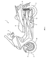
- Fig. 1 is a side view showing a motorcycle 1 provided with an engine unit 10, which is an example of a mode for carrying out the invention.
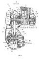
- Fig. 2 is a cross sectional view showing the engine unit 10.
- Fig. 3 is a partial, cross sectional view showing a continuously variable transmission 30 provided on the engine unit 10.
- Fig. 3 shows a drive side pulley 31 and a pulley moving mechanism 50 provided on the continuously variable transmission 30.
- the motorcycle 1 includes a front wheel 2 and a rear wheel 3 in addition to the engine unit 10.
- the front wheel 2 is arranged on the front of a vehicle body and an axle shaft 2a of the front wheel 2 is supported by a lower end of a front fork 4.
- a handle 5 is connected to an upper portion of the front fork 4.
- a seat 6 is arranged centrally of the vehicle body.
- the engine unit 10 is supported by a body frame (not shown) and is arranged below the seat 6.
- the engine unit 10 is able to swing vertically about a fulcrum defined by a pivot shaft 7 supported by the body frame.
- the engine unit 10 is provided to extend longitudinally of the vehicle body and a rear portion of the engine unit 10 supports the rear wheel 3.
- the motorcycle 1 is a unit swing type vehicle and the rear wheel 3 is able to swing vertically together with the engine unit 10.
- a lower end of a rear suspension 8 is connected to a rear end of the engine unit 10.
- An upper end of the rear suspension 8 is connected to a rear end of the body frame.
- the engine unit 10 includes an engine 11, the continuously variable transmission 30, a crank shaft 19, and a clutch 60.
- the engine 11 includes a piston 12 and a connecting rod 13.
- a mixture flowing into a cylinder 15 from an intake port (not shown) burns whereby the piston 12 reciprocates in the cylinder 15.
- a small end 13a of the connecting rod 13 is connected to the piston 12.
- a large end 13b of the connecting rod 13 is connected to a crank pin 19d of the crank shaft 19.
- the crank shaft 19 includes, in addition to the crank pin 19d, shaft portions 19a, 19b, a pair of arms 19c, 19c, and a pair of counterweights 19e, 19e, and receives a driving force of the engine 11 to thus be rotated.
- the shaft portions 19a, 19b extend in a vehicle width direction (direction indicated by A in Fig. 2 ).
- An end of the shaft portion 19a is rotatably mounted on a case cover 21 by a bearing 16a and a base of the shaft portion 19a is rotatably mounted on a crank case 22 by a bearing 16c.
- an end of the shaft portion 19b is rotatably mounted on a case cover 23 by a bearing 16b and a base of the shaft portion 19b is rotatably mounted on the crank case 22 by a bearing 16d.
- crank shaft 19 includes a cylindrical-shaped collar portion 19f (an enlarged view is shown in Fig. 3 ).
- the collar portion 19f is fitted on the shaft portion 19a and spline-coupled to an outer peripheral surface of the shaft portion 19a to rotate integrally therewith.
- a generator or alternator 40 is arranged outwardly of the shaft portion 19b in the vehicle width direction.
- a rotor 41 of the generator 40 is mounted to the shaft portion 19b so as to rotate therewith and a stator 42 is fixed to the case cover 23.
- the case cover 23 covers the generator 40 from an outward orientation or location in the vehicle width direction.
- the continuously variable transmission 30 is arranged outwardly of the shaft portion 19a in the vehicle width direction.
- the continuously variable transmission 30 includes the drive side pulley 31, a driven side pulley 34, and a belt 37 wound around the drive side pulley 31 and the driven side pulley 34 to transmit torque of the drive side pulley 31 to the driven side pulley 34.
- the drive side pulley 31 includes a pair of moving pulley 32 and a non-moving pulley 33, which are opposed to each other in an axial direction.
- the moving pulley 32 and the non-moving pulley 33 are provided in a manner to rotate together with the shaft portion 19a.
- the non-moving pulley 33 is spline-fitted onto the end of the shaft portion 19a.
- the cylindrical-shaped collar portion 19f is fitted onto the shaft portion 19a.
- the moving pulley 32 includes an axially extending cylindrical-shaped boss or hub portion 32a and a flange portion 32d extending radially from an outer end of the boss portion 32a in the vehicle width direction.
- the shaft portion 19a and the collar portion 19f are fitted into the boss portion 32a.
- a plurality of keys (detent member) 39 are radially inserted into the boss portion 32a and the collar portion 19f thus permitting the collar portion 19f and the moving pulley 32 to rotate together.
- the moving pulley 32 is movable axially of the crank shaft 19.
- the non-moving pulley 33 is inhibited from moving axially.
- the flange portion 32d of the moving pulley 32 and the non-moving pulley 33 are conical-shaped members, between which the belt 37 is interposed.
- a diameter of that portion of the drive side pulley 31, on which the belt 37 is stretched, is determined according to a position of the moving pulley 32 in the axial direction.
- the engine unit 10 includes the pulley moving mechanism 50 and the moving pulley 32 is axially moved by the operation of the pulley moving mechanism 50.
- the pulley moving mechanism 50 will be described later in detail.
- the driven side pulley 34 includes a pair of moving pulley 35 and a non-moving pulley 36, which are opposed to each other in an axial direction.
- the non-moving pulley 36 includes a cylindrical-shaped guide portion 36a and a flange portion 36b extending radially from an end of the guide portion 36a.
- the guide portion 36a extends axially of a drive shaft 71 arranged rearwardly of the crank shaft 19 to be fitted onto the drive shaft 71. Also, the guide portion 36a is provided so as to idle relative to the drive shaft 71 and inhibited from moving axially of the drive shaft 71.
- the moving pulley 35 is fitted onto the guide portion 36a to be movable axially of the drive shaft 71 along the guide portion 36a.
- the moving pulley 35 and the flange portion 36b of the non-moving pulley 36 are conical-shaped members, between which the belt 37 is interposed.
- the moving pulley 35 is biased toward the flange portion 36b by a restoring force of a spring 38.
- the moving pulley 32 As described above, as the moving pulley 32 is axially moved, a diameter of that portion of the drive side pulley 31, on which the belt 37 is stretched, is varied.
- the moving pulley 35 is correspondingly moved axially and a diameter of that portion of the driven side pulley 34, on which the belt 37 is stretched, is varied. Thereby, the continuously variable transmission 30 is varied steplessly in speed reduction ratio.
- the clutch 60 is arranged on an axis of the drive shaft 71 outwardly of the driven side pulley 34 in the vehicle width direction.
- the clutch 60 is a centrifugal clutch and includes a cylindrical-shaped clutch outer 61 having a bottom and a clutch weight 62 arranged inside the clutch outer 61.
- the clutch weight 62 is provided so as to idle relative to the drive shaft 71.
- the clutch weight 62 rotates together with the driven side pulley 34 and is provided to be radially movable according to a rotating speed thereof.
- the clutch outer 61 is provided to rotate together with the drive shaft 71.
- the clutch weight 62 moves radially to generate a frictional force between it and an inner peripheral surface of the clutch outer 61.
- the clutch outer 61 interlocks with the clutch weight 62, so that torque of the driven side pulley 34 is transmitted to the drive shaft 71 through the clutch weight 62 and the clutch outer 61.
- the drive shaft 71 is arranged away from an axle shaft 3a of the rear wheel 3.
- a gear 3b rotating with the axle shaft 3a is fitted onto the axle shaft 3a.
- a gear 71a is formed on an outer peripheral surface of the drive shaft 71.
- the pulley moving mechanism 50 is one, which moves the moving pulley 32 of the drive side pulley 31 axially to vary a speed reduction ratio by the continuously variable transmission 30.
- the pulley moving mechanism 50 moves the moving pulley 32 on the basis of, for example, a throttle operation by a passenger, engine speed, etc.
- the pulley moving mechanism 50 includes, as shown in Fig. 3 , an electric motor 51, a first intermediate shaft 52, a second intermediate shaft 53, a driven gear 54, a sliding member 55, a guide member 56, a bearing 57, and a support member 58.
- Fitted onto the first intermediate shaft 52 is a first reduction gear 52a, which meshes with an output shaft 51a of the electric motor 51 and rotates integrally with the first intermediate shaft 52. Also, a gear 52b having a smaller diameter than that of the first reduction gear 52a is formed on an outer peripheral surface of the first intermediate shaft 52. Fitted onto the second intermediate shaft 53 is a second reduction gear 53a, which meshes with the gear 52b of the first intermediate shaft 52 and rotates integrally with the second intermediate shaft 53.
- the driven gear 54 is arranged coaxially with the shaft portion 19a to mesh with the second reduction gear 53a.
- An opening is formed centrally of the driven gear 54 and the sliding member 55 is fitted into the opening.
- the sliding member 55 is coupled to an inside of the opening of the driven gear 54 by, for example, spline to rotate integrally with the driven gear 54.
- the sliding member 55 is a cylindrical-shaped member arranged on the axis of the shaft portion 19a and formed on an outer peripheral surface thereof with a feed screw (for example, male thread) 55a.
- the guide member 56 is also a cylindrical-shaped member arranged on the axis of the shaft portion 19a. An inner edge of the guide member 56 in the vehicle width direction is fixed to a support member 59 mounted to the crank case 22. Thereby, the guide member 56 is inhibited from moving axially.
- the guide member 56 is formed on an inner peripheral surface thereof with a feed screw (for example, female thread) 56a, which meshes with the feed screw 55a of the sliding member 55.
- the support member 59 is an annular-shaped member, and a bearing 17 is arranged on inner peripheral surface of the annular-shaped member.
- the support member 59 is supported through the bearing 17 by a support member 18, which is arranged inside the bearing 17 to interlock with the shaft portion 19a, to be independent of rotation of the shaft portion 19a.
- the second reduction gear 53a is formed from a resin, which contains, for example, a lubricant, whereby the gear 52b of the first intermediate shaft 52 and the driven gear 54 are maintained in lubricating ability even in the case where they are not supplied with a lubricating oil or the like.
- the support member 58 is a cylindrical-shaped member arranged coaxially with the shaft portion 19a. An inside diameter of the support member 58 corresponds to an outside diameter of the boss portion 32a of the moving pulley 32 and the boss portion 32a is fitted into the support member 58.
- the support member 58 is arranged inside the bearing 57 arranged inside the sliding member 55. The support member 58 supports the sliding member 55 with the bearing 57 therebetween so as to have the same rotating about the shaft portion 19a.
- the sliding member 55 interposes an outer peripheral side of the bearing 57 between it and a circlip 55b mounted to an end thereof and the support member 58 interposes an inner peripheral side of the bearing 57 between it and a circlip 58b mounted to an end thereof.
- the pulley moving mechanism 50 is arranged between the case cover 21 and the crank case 22.
- a bearing 52c supporting the first intermediate shaft 52 and a bearing 53c supporting the second intermediate shaft 53 are supported by the case cover 21, and a bearing 52d supporting the first intermediate shaft 52 and a bearing 53d supporting the second intermediate shaft 53 are supported by the crank case 22.
- FIG. 4 is a cross sectional view showing, in enlarged scale, the moving pulley 32 of the drive side pulley 31 and Fig. 5 is a plan view showing the moving pulley 32.
- the shaft portion 19a, the collar portion 19f, and the support member 58 are shown together with the moving pulley 32.
- an inner end of the collar portion 19f in the vehicle width direction abuts against a base 19g of the shaft portion 19a with the support member 18 therebetween.
- the non-moving pulley 33 is fitted onto the shaft portion 19a from outwardly of the collar portion 19f in the vehicle width direction and a nut 72 is further fitted onto the shaft portion from outwardly of the non-moving pulley 33.
- the collar portion 19f is inhibited from moving axially.
- the collar portion 19f is coupled to the outer peripheral surface of the shaft portion 19a by an axially extending spline 19h and the nut 72 is removed to enable removing the collar portion 19f from the shaft portion 19a.
- the collar portion 19f includes a cylindrical-shaped lubricant holding portion 19j in the vicinity of a center in the axial direction.
- An inside diameter of the lubricant holding portion 19j is larger than an inside diameter of the remaining portion of the collar portion 19f.
- a clearance is provided between the lubricant holding portion 19j and the outer peripheral surface of the shaft portion 19a.
- the clearance is filled with a lubricant.
- the lubricant holding portion 19j is formed with a plurality (here, two) of keyholes (shaft side hole) 19i, 19i, through which the keys 39, 39 are inserted.
- the keyholes 19i, 19i are provided at equal intervals circumferentially of the shaft portion 19a and extend through the lubricant holding portion 19j. Ends 39a, 39a of the keys 39, 39 are press fitted into the keyholes 19i, 19i whereby the keys 39, 39 are fixed to the keyholes 19i, 19i.
- the moving pulley 32 is arranged inwardly of the non-moving pulley 33 in the vehicle width direction and the cylindrical-shaped boss portion 32a extends axially of the shaft portion 19a.
- the boss portion 32a is formed with guide holes (boss side hole) 32b, 32b, which extend radially through the boss portion 32a and through which the keys 39, 39 are inserted.
- the guide holes 32b, 32b are provided at equal intervals circumferentially of the shaft portion 19a to respectively correspond to the keyholes 19i, 19i of the collar portion 19f.
- the guide holes 32b, 32b are provided on opposite sides to each other with the axis of the shaft portion 19a therebetween.
- the guide holes 32b, 32b are axially extending slots and guide relative movements of the keys 39, 39 in the axial direction.
- both ends 32e, 32e of the guide hole 32b are formed to be larger in width than a central portion of the guide hole 32b.
- Fig. 6 is a view illustrating an example of the positional relationship between the keys 39, 39 and the crank pin 19d.
- ⁇ indicates an angle, which is formed by a straight line Lk passing through the keys 39 and an axis Co of the shaft portion 19a and a straight line Ls in a rotating direction (direction indicated by B in Fig. 6 ) of the crank shaft 19, on the basis of the straight line Ls passing through the axis Co of the crank shaft 19 and a center Po of the crank pin 19d.
- subscripts are added to the respective keys 39, 39 in order to discriminate between the two keys 39, 39.
- one of the keys 39-1 is arranged in a position, in which the angle ⁇ is at least 45° but at most 90° (about 80° in Fig. 6 ). Also, the other of the keys 39-2 is arranged on an opposite side to the one 39-1 of the keys with the axis Co of the shaft portion 19a therebetween.
- the keys 39 have a height amounting substantially to the sum of a depth of the guide hole 32b and a depth of the keyhole 19i.
- the keyholes 19i are slightly larger in axial (the vehicle width direction) length than the keys 39.
- the ends 39a of the keys 39 are press fitted into the keyholes 19i, clearances are provided on both left and right sides (inward and outward in the vehicle width direction) of the keys 39.
- the lubricant filled between an inner peripheral surface of the lubricant holding portion 19j and the outer peripheral surface of the shaft portion 19a passes through the clearances to flow outside the lubricant holding portion 19j to lubricate the guide holes 32b and the bases 39b of the keys 39.
- the boss portion 32a of the moving pulley 32 is fitted into the cylindrical-shaped support member 58 described above.
- the moving pulley 32 is inhibited from moving relative to the support member 58 in the axial direction and moves axially together with the support member 58 and the sliding member 55.
- the support member 58 is interposed between the flange portion 32d of the moving pulley 32 and a circlip 32f mounted to an inner end of the boss portion 32a in the vehicle width direction, whereby the support member 58 is inhibited from moving relative to the moving pulley 32 in the axial direction.
- the support member 58 closes the guide holes 32b, 32b from radially outward to prevent inadvertent removal of the keys 39, 39.
- a lubricant holding portion 32c being smaller in outside diameter than the remaining portion of the boss portion 32a is provided in the vicinity of a center of the boss portion 32a in the vehicle width direction (direction indicated by A in Fig. 5 ).
- the guide holes 32b are formed across the lubricant holding portion 32c. A lubricating oil flowing outside the lubricant holding portion 19j described above passes through the guide holes 32b to flow outside the boss portion 32a.
- the outflowing lubricating oil enters between an outer peripheral surface of the lubricant holding portion 32c and an inner peripheral surface of the support member 58 and further enters between an outer peripheral surface of the remaining portion of the boss portion 32a and the inner peripheral surface of the support member 58 to provide for lubrication therebetween.
- sealing is provided between an outer peripheral surface of the collar portion 19f and an inner peripheral surface of the boss portion 32a and between an outer peripheral surface of the boss portion 32a and the inner peripheral surface of the support member 58.
- annular oil seal 73a is arranged between the outer end of the boss portion 32a in the vehicle width direction and the outer peripheral surface of the collar portion 19f.
- annular oil seal 73b is arranged between the inner end of the boss portion 32a in the vehicle width direction and the outer peripheral surface of the collar portion 19f.
- annular oil seal 73c is arranged between an outer end of the support member 58 in the vehicle width direction and the outer peripheral surface of the boss portion 32a and an oil seal 73d is arranged between an inner end of the support member 58 in the vehicle width direction and the outer peripheral surface of the boss portion 32a.
- the temporary detent member is removed and the key 39 is inserted into that set out of the keyholes 19i and the guide holes 32b, into which the temporary detent member has been inserted, to have the ends 39a thereof press fitted into the keyhole 19i in the same manner as described above.
- the collar portion 19f is formed with a plurality (here, two) of keyholes 19i, 19i and the boss portion 32a is formed with the guide holes 32b, 32b positioned corresponding to the keyholes 19i, 19i.
- the keyholes 19i into which the keys 39 are press fitted, extend through the collar portion 19f.
- the keyholes 19i, 19i are formed on the lubricant holding portion 19j of the collar portion 19f. Thereby, it is possible to lubricate the keys 39 and the guide holes 32b.
- Fig. 7 is a cross sectional view showing, in enlarged scale, a moving pulley 32 provided on an engine unit 10A according to the embodiment.
- the same parts as those described above are denoted by the same reference numerals as in the latter and an explanation therefor is omitted.
- two keyholes 32g, 32g are formed on a boss portion 32a on the engine unit 10A to be positioned on opposite sides to each other with an axis of a shaft portion 19a therebetween.
- axially extending guide holes 19k, 19k are formed on a collar portion 19f to be positioned corresponding to the keyholes 32g, 32g.
- Keys 39, 39, respectively, are press fitted into the keyholes 32g, 32g and fixed to the keyholes 32g, 32g.
- the guide holes 19k, 19k, respectively receive ends 39a, 39a of the keys 39, 39 to guide relative movements of the moving pulley 32 and a crank shaft 19 in an axial direction.
- the keyholes 19i and the guide holes 32b are formed two by two, but keyholes and guide holes are not limited in number thereto.
- three keyholes 19i may be formed on the collar portion 19f and guide holes 32b may be formed in respective positions, which correspond to the three keyholes 19i, on the boss portion 32a.
- Fig. 8 is a view illustrating an example of the positional relationship between the keys 39 and a crank pin 19d in the embodiment.
- the same parts as those in Fig. 6 are denoted by the same reference numerals as in the latter, an explanation therefor is omitted, and subscripts are to the three keys 39. As shown in Fig.
- the key 39-1 is arranged in a position, in which the angle ⁇ is at least 45° but at most 90° (about 80° in Fig. 8 ) .
- the key 39-2 is arranged on an opposite side to the key 39-1 with an axis Co of a shaft portion 19a therebetween.
- the key 39-3 is arranged toward a crank pin 19d relative to the key 39-1 and the key 39-2 and an angle ⁇ formed between a straight line Lk' passing through the key 39-3 and an axis Co of the shaft portion 19a and a straight line Lk passing through the key 39-1 and the axis Co of the shaft portion 19a is about 90°.
- the keys 39 are press fitted into the keyholes 19i.
- bolt holes may be formed on the collar portion 19f and instead of the keys 39, bolts may be fixed to the bolt holes.
- the engine 11, in which a mixture is burnt for driving is mounted as a power source for a vehicle.
- the power source may comprise an electric motor driven by electric power, or a hybrid engine composed of a combination of an electric motor and an engine.
Landscapes
- Engineering & Computer Science (AREA)
- General Engineering & Computer Science (AREA)
- Mechanical Engineering (AREA)
- Transmissions By Endless Flexible Members (AREA)
- Devices For Conveying Motion By Means Of Endless Flexible Members (AREA)
- General Details Of Gearings (AREA)
- Mechanical Coupling Of Light Guides (AREA)
- Electrical Discharge Machining, Electrochemical Machining, And Combined Machining (AREA)
- Vehicle Body Suspensions (AREA)
- Pulleys (AREA)
Abstract
Description
- The present invention relates to a technology for assembling a rotating shaft provided to receive a driving force of a power source to rotate, and a pulley, around which a belt for transmission of a driving force is wound.
- In a straddle-type vehicle such as motorcycle, etc., some engine units include an engine and a continuously variable transmission for stepless change in reduction ratio. Continuously variable transmissions generally include a belt for transmission of a driving force of an engine to a drive wheel, and a pulley (referred below to as moving pulley), around which the belt is wound and which moves in an axial direction to vary the effective diameter of the portion on which the belt is stretched. In some conventional continuously variable transmissions, keyways are formed on a boss of a moving pulley and a crank shaft, onto which the boss is fitted, and radially extending keys are inserted into the keyways, whereby the moving pulley and the crank shaft are permitted to rotate integrally. Such an arrangement is disclosed in, for example,
JP-A-2006-118630 - With the engine unit disclosed in
JP-A-2006-118630 - The invention has been thought of in view of the problem and has its one object to provide a power unit capable of improving a work, in which a moving pulley is assembled, in workability, and a straddle-type vehicle.
- In order to solve the problem, a power unit according to the invention comprises a power source, a rotating shaft, which receives a driving force output from the power source to rotate, and a moving pulley including a cylindrical-shaped boss portion extending in an axial direction of the rotating shaft, the boss portion being fitted onto the rotating shaft to be movable in the axial direction. The rotating shaft is formed on an outer peripheral surface thereof with a plurality of shaft side holes, and a plurality of boss side holes extending through the boss portion are formed in positions, which correspond to the plurality of shaft side holes, on the boss portion. The power unit further comprises a plurality of detent members inserted through the plurality of shaft side holes and the plurality of boss side holes, one ends of the detent members are mounted to one of the plurality of shaft side holes and the plurality of boss side holes, and the other of the plurality of shaft side holes and the plurality of boss side holes comprise slots extending in the axial direction, and receiving the other ends of the detent members to guide relative movements of the moving pulley and the rotating shaft in the axial direction.
- Also, in order to solve the problem, a straddle-type vehicle according to the invention comprises the power unit.
- According to the invention, in a work, in which a moving pulley and a crank shaft are assembled, one of pairs of the plurality of shaft side holes and the plurality of boss side holes can be used to hold rotated positions of the moving pulley and the crank shaft. As a result, it is possible to prevent the shaft side holes and the boss side holes from getting out of position, thus enabling improving the assembling work in workability. In addition, a straddle-type vehicle herein includes, for example, motorcycle (including scooters), four-wheeled buggy, snowmobile, two-wheeled electric motor car, etc.
- Also, according to an embodiment of the invention, the plurality of shaft side holes are provided at equal intervals on an outer peripheral surface of the rotating shaft in a circumferential direction of the rotating shaft, and the plurality of boss side holes are provided at equal intervals on the boss portion in the circumferential direction. According to the embodiment, centrifugal forces generated by rotation of the rotating shaft can be balanced with each other, so that it is possible to achieve stability in rotation of the rotating shaft. According to the embodiment, the boss portion may be formed with two of the boss side holes and the rotating shaft may be formed with two of the shaft side holes.
- Also, according to an embodiment of the invention, the plurality of boss side holes comprise the slots extending in the axial direction. According to the embodiment, relative movements of the rotating shaft and the moving pulley can be made smooth as compared with the case where the plurality of shaft side holes comprise slots. That is, in the case where the other ends of the detent members are received in the slots to move along the slots, friction is generated between the other ends and the slots. Since the boss side holes are disposed outwardly of the shaft side holes in a diametrical direction of the rotating shaft, friction generated in the case where the other ends of the detent members move relatively along the boss side holes is small as compared with friction generated in the case where the other ends move along the shaft side holes. As a result, it is possible according to the embodiment to make relative movements of the rotating shaft and the moving pulley smooth as compared with the case where the plurality of shaft side holes comprise slots.
- Also, according to the embodiment of the invention, the rotating shaft includes a shaft portion, which receives a driving force of the power source to rotate, and a cylindrical-shaped collar portion formed with the plurality of shaft side holes and fitted onto the shaft portion to rotate together with the shaft portion, and the plurality of shaft side holes extend through the collar portion and the plurality of detent members are press fitted into the plurality of shaft side holes. According to the embodiment, as compared with the case where the shaft side holes comprise bottomed recesses, forces, with which the shaft side holes tend to push out the detent members are decreased, so that it is possible to prevent the detent members from coming off the shaft side holes. Also, in this case, the collar portion may include a cylindrical-shaped lubricant holding portion having a clearance between it and an outer peripheral surface of the shaft portion and accumulating a lubricant in the clearance, and the plurality of shaft side holes may extend through the lubricant holding portion. Thereby, it is possible to permeate a lubricant, which is accumulated between the outer peripheral surface of the shaft portion and the lubricant holding portion, outside the collar portion, thus enabling lubrication between the boss portion and the collar portion and between the boss side holes and the detent members.
- Also, according to an embodiment of the invention, the rotating shaft includes a shaft portion, which receives a driving force of the power source to rotate, and a cylindrical-shaped collar portion formed with the plurality of shaft side holes and fitted onto the shaft portion to rotate together with the shaft portion, and the collar portion is fitted onto the shaft portion so as to enable removal from the shaft portion. According to the embodiment, the work of exchanging the moving pulley, etc. can be performed by removing the collar portion from the shaft portion without removing the whole rotating shaft from the power unit.
- According to an aspect of the present invention there is provided a power unit comprising:
- a power source;
- a rotating shaft coupled to the power source and comprising a plurality of shaft side holes formed in a surface thereof;
- a moving pulley including a cylindrical-shaped boss portion extending in an axial direction of the rotating shaft, the boss portion being fitted onto the rotating shaft to be movable in the axial direction and comprising a plurality of boss side holes in a surface thereof; and
- a plurality of detent members inserted through the plurality of shaft side holes and the plurality of boss side holes,
- wherein one end of each detent member is mounted to a respective one of the plurality of shaft side holes and the plurality of boss side holes, and
- the other of the plurality of shaft side holes and the plurality of boss side holes comprises slots extending in the axial direction, and adapted to receive the other end of a respective detent member to guide relative axial movement of the moving pulley and the rotating shaft.
- These and other aspects of the present invention will now be described, by way of example only, with reference to the accompanying drawings, in which:
-
Fig. 1 is a side view showing a motorcycle provided with an engine unit, which is an example of a mode for carrying out the invention; -
Fig. 2 is a cross sectional view showing the engine unit; -
Fig. 3 is a partial, cross sectional view showing a continuously variable transmission provided on the engine unit; -
Fig. 4 is a cross sectional view showing, in enlarged scale, a moving pulley provided on the drive side pulley. -
Fig. 5 is a plan view showing the moving pulley; -
Fig. 6 is a view illustrating an example of the positional relationship between keys and a crank pin; -
Fig. 7 is a cross sectional view showing, in enlarged scale, a moving pulley provided on an engine unit according to a further mode for carrying out the invention; and -
Fig. 8 is a view illustrating an example of the positional relationship between keys and a crank pin in a further mode for carrying out the invention. -
Fig. 1 is a side view showing a motorcycle 1 provided with anengine unit 10, which is an example of a mode for carrying out the invention.Fig. 2 is a cross sectional view showing theengine unit 10.Fig. 3 is a partial, cross sectional view showing a continuouslyvariable transmission 30 provided on theengine unit 10.Fig. 3 shows adrive side pulley 31 and apulley moving mechanism 50 provided on the continuouslyvariable transmission 30. - As shown in
Fig. 1 , the motorcycle 1 includes afront wheel 2 and a rear wheel 3 in addition to theengine unit 10. Thefront wheel 2 is arranged on the front of a vehicle body and anaxle shaft 2a of thefront wheel 2 is supported by a lower end of a front fork 4. A handle 5 is connected to an upper portion of the front fork 4. Aseat 6 is arranged centrally of the vehicle body. Theengine unit 10 is supported by a body frame (not shown) and is arranged below theseat 6. Theengine unit 10 is able to swing vertically about a fulcrum defined by apivot shaft 7 supported by the body frame. Theengine unit 10 is provided to extend longitudinally of the vehicle body and a rear portion of theengine unit 10 supports the rear wheel 3. The motorcycle 1 is a unit swing type vehicle and the rear wheel 3 is able to swing vertically together with theengine unit 10. A lower end of arear suspension 8 is connected to a rear end of theengine unit 10. - An upper end of the
rear suspension 8 is connected to a rear end of the body frame. - As shown in
Fig. 2 , theengine unit 10 includes anengine 11, the continuouslyvariable transmission 30, acrank shaft 19, and a clutch 60. Theengine 11 includes apiston 12 and a connectingrod 13. A mixture flowing into acylinder 15 from an intake port (not shown) burns whereby thepiston 12 reciprocates in thecylinder 15. Asmall end 13a of the connectingrod 13 is connected to thepiston 12. Alarge end 13b of the connectingrod 13 is connected to a crankpin 19d of thecrank shaft 19. - The
crank shaft 19 includes, in addition to the crankpin 19d,shaft portions arms counterweights engine 11 to thus be rotated. - The
shaft portions Fig. 2 ). An end of theshaft portion 19a is rotatably mounted on acase cover 21 by abearing 16a and a base of theshaft portion 19a is rotatably mounted on a crankcase 22 by abearing 16c. Also, an end of theshaft portion 19b is rotatably mounted on acase cover 23 by abearing 16b and a base of theshaft portion 19b is rotatably mounted on thecrank case 22 by abearing 16d. Thearms shaft portions crank pin 19d in a position away from axes of theshaft portions counterweights arms shaft portions crank shaft 19 includes a cylindrical-shapedcollar portion 19f (an enlarged view is shown inFig. 3 ). Thecollar portion 19f is fitted on theshaft portion 19a and spline-coupled to an outer peripheral surface of theshaft portion 19a to rotate integrally therewith. - A generator or
alternator 40 is arranged outwardly of theshaft portion 19b in the vehicle width direction. Arotor 41 of thegenerator 40 is mounted to theshaft portion 19b so as to rotate therewith and astator 42 is fixed to thecase cover 23. The case cover 23 covers thegenerator 40 from an outward orientation or location in the vehicle width direction. - The continuously
variable transmission 30 is arranged outwardly of theshaft portion 19a in the vehicle width direction. The continuouslyvariable transmission 30 includes thedrive side pulley 31, a drivenside pulley 34, and abelt 37 wound around thedrive side pulley 31 and the drivenside pulley 34 to transmit torque of thedrive side pulley 31 to the drivenside pulley 34. - The
drive side pulley 31 includes a pair of movingpulley 32 and anon-moving pulley 33, which are opposed to each other in an axial direction. The movingpulley 32 and thenon-moving pulley 33 are provided in a manner to rotate together with theshaft portion 19a. Specifically, thenon-moving pulley 33 is spline-fitted onto the end of theshaft portion 19a. Also, as described above, the cylindrical-shapedcollar portion 19f is fitted onto theshaft portion 19a. As shown inFig. 3 , the movingpulley 32 includes an axially extending cylindrical-shaped boss orhub portion 32a and aflange portion 32d extending radially from an outer end of theboss portion 32a in the vehicle width direction. Theshaft portion 19a and thecollar portion 19f are fitted into theboss portion 32a. A plurality of keys (detent member) 39 are radially inserted into theboss portion 32a and thecollar portion 19f thus permitting thecollar portion 19f and the movingpulley 32 to rotate together. - The moving
pulley 32 is movable axially of thecrank shaft 19. On the other hand, thenon-moving pulley 33 is inhibited from moving axially. Theflange portion 32d of the movingpulley 32 and thenon-moving pulley 33 are conical-shaped members, between which thebelt 37 is interposed. A diameter of that portion of thedrive side pulley 31, on which thebelt 37 is stretched, is determined according to a position of the movingpulley 32 in the axial direction. In addition, as shown inFig. 3 , theengine unit 10 includes thepulley moving mechanism 50 and the movingpulley 32 is axially moved by the operation of thepulley moving mechanism 50. Thepulley moving mechanism 50 will be described later in detail. - As shown in
Fig. 2 , the drivenside pulley 34 includes a pair of movingpulley 35 and anon-moving pulley 36, which are opposed to each other in an axial direction. Thenon-moving pulley 36 includes a cylindrical-shapedguide portion 36a and aflange portion 36b extending radially from an end of theguide portion 36a. Theguide portion 36a extends axially of adrive shaft 71 arranged rearwardly of thecrank shaft 19 to be fitted onto thedrive shaft 71. Also, theguide portion 36a is provided so as to idle relative to thedrive shaft 71 and inhibited from moving axially of thedrive shaft 71. The movingpulley 35 is fitted onto theguide portion 36a to be movable axially of thedrive shaft 71 along theguide portion 36a. The movingpulley 35 and theflange portion 36b of thenon-moving pulley 36 are conical-shaped members, between which thebelt 37 is interposed. The movingpulley 35 is biased toward theflange portion 36b by a restoring force of aspring 38. - As described above, as the moving
pulley 32 is axially moved, a diameter of that portion of thedrive side pulley 31, on which thebelt 37 is stretched, is varied. The movingpulley 35 is correspondingly moved axially and a diameter of that portion of the drivenside pulley 34, on which thebelt 37 is stretched, is varied. Thereby, the continuouslyvariable transmission 30 is varied steplessly in speed reduction ratio. - The clutch 60 is arranged on an axis of the
drive shaft 71 outwardly of the drivenside pulley 34 in the vehicle width direction. In the example described herein, the clutch 60 is a centrifugal clutch and includes a cylindrical-shaped clutch outer 61 having a bottom and aclutch weight 62 arranged inside the clutch outer 61. Theclutch weight 62 is provided so as to idle relative to thedrive shaft 71. Also, theclutch weight 62 rotates together with the drivenside pulley 34 and is provided to be radially movable according to a rotating speed thereof. The clutch outer 61 is provided to rotate together with thedrive shaft 71. When the drivenside pulley 34 is increased in rotating speed, theclutch weight 62 moves radially to generate a frictional force between it and an inner peripheral surface of the clutch outer 61. Thereby, the clutch outer 61 interlocks with theclutch weight 62, so that torque of the drivenside pulley 34 is transmitted to thedrive shaft 71 through theclutch weight 62 and the clutch outer 61. - In the example described herein, the
drive shaft 71 is arranged away from anaxle shaft 3a of the rear wheel 3. Agear 3b rotating with theaxle shaft 3a is fitted onto theaxle shaft 3a. Agear 71a is formed on an outer peripheral surface of thedrive shaft 71. Thegear 71a and thegear 3b on theaxle shaft 3a, respectively, mesh with an intermediate shaft (not shown) whereby torque transmitted to thedrive shaft 71 is transmitted to theaxle shaft 3a through the intermediate shaft. - A detailed explanation will be given to a construction, which rotates the
drive side pulley 31 and thecrank shaft 19 integrally, and thepulley moving mechanism 50. Initially, an explanation will be given to thepulley moving mechanism 50. - As described above, the
pulley moving mechanism 50 is one, which moves the movingpulley 32 of thedrive side pulley 31 axially to vary a speed reduction ratio by the continuouslyvariable transmission 30. Thepulley moving mechanism 50 moves the movingpulley 32 on the basis of, for example, a throttle operation by a passenger, engine speed, etc. In the example described herein, thepulley moving mechanism 50 includes, as shown inFig. 3 , anelectric motor 51, a firstintermediate shaft 52, a secondintermediate shaft 53, a drivengear 54, a slidingmember 55, aguide member 56, abearing 57, and asupport member 58. - Fitted onto the first
intermediate shaft 52 is afirst reduction gear 52a, which meshes with anoutput shaft 51a of theelectric motor 51 and rotates integrally with the firstintermediate shaft 52. Also, agear 52b having a smaller diameter than that of thefirst reduction gear 52a is formed on an outer peripheral surface of the firstintermediate shaft 52. Fitted onto the secondintermediate shaft 53 is asecond reduction gear 53a, which meshes with thegear 52b of the firstintermediate shaft 52 and rotates integrally with the secondintermediate shaft 53. - The driven
gear 54 is arranged coaxially with theshaft portion 19a to mesh with thesecond reduction gear 53a. An opening is formed centrally of the drivengear 54 and the slidingmember 55 is fitted into the opening. - The sliding
member 55 is coupled to an inside of the opening of the drivengear 54 by, for example, spline to rotate integrally with the drivengear 54. The slidingmember 55 is a cylindrical-shaped member arranged on the axis of theshaft portion 19a and formed on an outer peripheral surface thereof with a feed screw (for example, male thread) 55a. Theguide member 56 is also a cylindrical-shaped member arranged on the axis of theshaft portion 19a. An inner edge of theguide member 56 in the vehicle width direction is fixed to asupport member 59 mounted to the crankcase 22. Thereby, theguide member 56 is inhibited from moving axially. Theguide member 56 is formed on an inner peripheral surface thereof with a feed screw (for example, female thread) 56a, which meshes with thefeed screw 55a of the slidingmember 55. Thereby, when torque of theelectric motor 51 is transmitted from the drivengear 54, the slidingmember 55 is moved axially while rotating together with the drivengear 54. - In addition, the
support member 59 is an annular-shaped member, and abearing 17 is arranged on inner peripheral surface of the annular-shaped member. Thesupport member 59 is supported through the bearing 17 by asupport member 18, which is arranged inside the bearing 17 to interlock with theshaft portion 19a, to be independent of rotation of theshaft portion 19a. Also, thesecond reduction gear 53a is formed from a resin, which contains, for example, a lubricant, whereby thegear 52b of the firstintermediate shaft 52 and the drivengear 54 are maintained in lubricating ability even in the case where they are not supplied with a lubricating oil or the like. - The
support member 58 is a cylindrical-shaped member arranged coaxially with theshaft portion 19a. An inside diameter of thesupport member 58 corresponds to an outside diameter of theboss portion 32a of the movingpulley 32 and theboss portion 32a is fitted into thesupport member 58. Thesupport member 58 is arranged inside the bearing 57 arranged inside the slidingmember 55. Thesupport member 58 supports the slidingmember 55 with the bearing 57 therebetween so as to have the same rotating about theshaft portion 19a. - Relative movements of the sliding
member 55 and thesupport member 58 in the axial direction are inhibited and thesupport member 58 moves axially together with the slidingmember 55. In the example described herein, the slidingmember 55 interposes an outer peripheral side of thebearing 57 between it and acirclip 55b mounted to an end thereof and thesupport member 58 interposes an inner peripheral side of thebearing 57 between it and acirclip 58b mounted to an end thereof. Thereby, relative movements of the slidingmember 55 and thesupport member 58 in the axial direction are inhibited. - In addition, the
pulley moving mechanism 50 is arranged between thecase cover 21 and the crankcase 22. A bearing 52c supporting the firstintermediate shaft 52 and a bearing 53c supporting the secondintermediate shaft 53 are supported by thecase cover 21, and abearing 52d supporting the firstintermediate shaft 52 and abearing 53d supporting the secondintermediate shaft 53 are supported by thecrank case 22. - An explanation will be given to a construction, which rotates the
drive side pulley 31 and thecrank shaft 19 integrally.Fig. 4 is a cross sectional view showing, in enlarged scale, the movingpulley 32 of thedrive side pulley 31 andFig. 5 is a plan view showing the movingpulley 32. InFig. 4 , theshaft portion 19a, thecollar portion 19f, and thesupport member 58 are shown together with the movingpulley 32. - As shown in
Fig. 3 , an inner end of thecollar portion 19f in the vehicle width direction abuts against abase 19g of theshaft portion 19a with thesupport member 18 therebetween. Thenon-moving pulley 33 is fitted onto theshaft portion 19a from outwardly of thecollar portion 19f in the vehicle width direction and anut 72 is further fitted onto the shaft portion from outwardly of thenon-moving pulley 33. Thereby, thecollar portion 19f is inhibited from moving axially. Also, as shown inFig. 4 , thecollar portion 19f is coupled to the outer peripheral surface of theshaft portion 19a by anaxially extending spline 19h and thenut 72 is removed to enable removing thecollar portion 19f from theshaft portion 19a. - The
collar portion 19f includes a cylindrical-shapedlubricant holding portion 19j in the vicinity of a center in the axial direction. An inside diameter of thelubricant holding portion 19j is larger than an inside diameter of the remaining portion of thecollar portion 19f. Thereby, a clearance is provided between thelubricant holding portion 19j and the outer peripheral surface of theshaft portion 19a. The clearance is filled with a lubricant. Also, thelubricant holding portion 19j is formed with a plurality (here, two) of keyholes (shaft side hole) 19i, 19i, through which thekeys keyholes shaft portion 19a and extend through thelubricant holding portion 19j.Ends keys keyholes keys keyholes - As shown in
Fig. 3 , the movingpulley 32 is arranged inwardly of thenon-moving pulley 33 in the vehicle width direction and the cylindrical-shapedboss portion 32a extends axially of theshaft portion 19a. As shown inFig. 4 or5 , theboss portion 32a is formed with guide holes (boss side hole) 32b, 32b, which extend radially through theboss portion 32a and through which thekeys shaft portion 19a to respectively correspond to thekeyholes collar portion 19f. In the example described herein, the guide holes 32b, 32b are provided on opposite sides to each other with the axis of theshaft portion 19a therebetween. The guide holes 32b, 32b are axially extending slots and guide relative movements of thekeys Fig. 5 , both ends 32e, 32e of theguide hole 32b are formed to be larger in width than a central portion of theguide hole 32b. -
Fig. 6 is a view illustrating an example of the positional relationship between thekeys crank pin 19d. In addition, in the illustration, θ indicates an angle, which is formed by a straight line Lk passing through thekeys 39 and an axis Co of theshaft portion 19a and a straight line Ls in a rotating direction (direction indicated by B inFig. 6 ) of thecrank shaft 19, on the basis of the straight line Ls passing through the axis Co of thecrank shaft 19 and a center Po of thecrank pin 19d. Also, in the figure, subscripts are added to therespective keys keys - As shown in
Fig. 6 , in the example described herein, one of the keys 39-1 is arranged in a position, in which the angle θ is at least 45° but at most 90° (about 80° inFig. 6 ). Also, the other of the keys 39-2 is arranged on an opposite side to the one 39-1 of the keys with the axis Co of theshaft portion 19a therebetween. - As shown in
Fig. 4 , thekeys 39 have a height amounting substantially to the sum of a depth of theguide hole 32b and a depth of thekeyhole 19i. Thereby, when the ends 39a of thekeys 39 are press fitted into thekeyholes 19i, bases 39b (radially outward) of thekeys 39 engage with the guide holes 32b in the rotating direction of theshaft portion 19a. The guide holes 32b receive thebases 39b of thekeys 39 inside thereof to guide relative movements of thecollar portion 19f in the axial direction. - Also, as shown in
Fig. 4 , thekeyholes 19i are slightly larger in axial (the vehicle width direction) length than thekeys 39. Thereby, even in a state, in which theends 39a of thekeys 39 are press fitted into thekeyholes 19i, clearances are provided on both left and right sides (inward and outward in the vehicle width direction) of thekeys 39. As a result, the lubricant filled between an inner peripheral surface of thelubricant holding portion 19j and the outer peripheral surface of theshaft portion 19a passes through the clearances to flow outside thelubricant holding portion 19j to lubricate the guide holes 32b and thebases 39b of thekeys 39. - The
boss portion 32a of the movingpulley 32 is fitted into the cylindrical-shapedsupport member 58 described above. The movingpulley 32 is inhibited from moving relative to thesupport member 58 in the axial direction and moves axially together with thesupport member 58 and the slidingmember 55. In the example, thesupport member 58 is interposed between theflange portion 32d of the movingpulley 32 and acirclip 32f mounted to an inner end of theboss portion 32a in the vehicle width direction, whereby thesupport member 58 is inhibited from moving relative to the movingpulley 32 in the axial direction. Also, thesupport member 58 closes the guide holes 32b, 32b from radially outward to prevent inadvertent removal of thekeys - As shown in
Fig. 5 , alubricant holding portion 32c being smaller in outside diameter than the remaining portion of theboss portion 32a is provided in the vicinity of a center of theboss portion 32a in the vehicle width direction (direction indicated by A inFig. 5 ). The guide holes 32b are formed across thelubricant holding portion 32c. A lubricating oil flowing outside thelubricant holding portion 19j described above passes through the guide holes 32b to flow outside theboss portion 32a. The outflowing lubricating oil enters between an outer peripheral surface of thelubricant holding portion 32c and an inner peripheral surface of thesupport member 58 and further enters between an outer peripheral surface of the remaining portion of theboss portion 32a and the inner peripheral surface of thesupport member 58 to provide for lubrication therebetween. - In addition, sealing is provided between an outer peripheral surface of the
collar portion 19f and an inner peripheral surface of theboss portion 32a and between an outer peripheral surface of theboss portion 32a and the inner peripheral surface of thesupport member 58. Specifically, as shown inFig. 4 , anannular oil seal 73a is arranged between the outer end of theboss portion 32a in the vehicle width direction and the outer peripheral surface of thecollar portion 19f. Also, anannular oil seal 73b is arranged between the inner end of theboss portion 32a in the vehicle width direction and the outer peripheral surface of thecollar portion 19f. Further, anannular oil seal 73c is arranged between an outer end of thesupport member 58 in the vehicle width direction and the outer peripheral surface of theboss portion 32a and anoil seal 73d is arranged between an inner end of thesupport member 58 in the vehicle width direction and the outer peripheral surface of theboss portion 32a. Thereby, without being splashed on thebelt 37 or the like, the lubricant flows between an inner peripheral surface of thecollar portion 19f and the outer peripheral surface of theshaft portion 19a, between the outer peripheral surface of thecollar portion 19f and the inner peripheral surface of theboss portion 32a, and between the outer peripheral surface of theboss portion 32a and the inner peripheral surface of thesupport member 58. - Finally, an explanation is given to an example of a way to fit the
collar portion 19f into theboss portion 32a of the movingpulley 32. Theboss portion 32a is fitted into thecollar portion 19f and either of them is turned to have positions of the twokeyholes collar portion 19f and theboss portion 32a is temporarily inserted into one set out of the twokeyholes 19i and the twoguide holes 32b, which are caused to positionally register with each other. Thereafter, the key 39 is inserted into the other set out of thekeyholes 19i and the guide holes 32b and theends 39a thereof are press fitted into thekeyhole 19i. Thereafter, the temporary detent member is removed and the key 39 is inserted into that set out of thekeyholes 19i and the guide holes 32b, into which the temporary detent member has been inserted, to have theends 39a thereof press fitted into thekeyhole 19i in the same manner as described above. - With the
engine unit 10 described above, thecollar portion 19f is formed with a plurality (here, two) ofkeyholes boss portion 32a is formed with the guide holes 32b, 32b positioned corresponding to thekeyholes pulley 32 to thecrank shaft 19, the key 39 can be press fitted into other set out of thekeyholes 19i and the guide holes 32b in a state, in which the temporary detent member described above is inserted into the one set out of thekeyholes 19i and the guide holes 32b, so that the assembling process is improved in terms of workability. - Also, since the two
keys 39 are inserted, a load applied on one key at the time of rotation of thecrank shaft 19 is decreased as compared with the case where only one key is inserted. As a result, the power unit is improved in durability. - Also, since the
keys shaft portion 19a therebetween, centrifugal forces generated by rotation of thecrank shaft 19 can be balanced with each other. - Also, the
keyholes 19i, into which thekeys 39 are press fitted, extend through thecollar portion 19f. Thereby, as compared with the case where keyholes comprise bottomed recesses, forces tending to push out thekeys 39 once press fitted are decreased, so that it is possible to prevent coming-off of thekeys 39. - Also, the
keyholes lubricant holding portion 19j of thecollar portion 19f. Thereby, it is possible to lubricate thekeys 39 and the guide holes 32b. - Also, since the
collar portion 19f can be removed from theshaft portion 19a, exchange of thedrive side pulley 31 can be achieved only by removing thecollar portion 19f from theshaft portion 19a without breaking up the crankcase 22 when thedrive side pulley 31 is to be exchanged. - In addition, the invention is not limited to the
engine unit 10 described above but affords various modifications. For example, in the above description, thekeys 39 are press fitted into thecollar portion 19f but the keys may be press fitted into aboss portion 32a of a movingpulley 32.Fig. 7 is a cross sectional view showing, in enlarged scale, a movingpulley 32 provided on anengine unit 10A according to the embodiment. In the figure, the same parts as those described above are denoted by the same reference numerals as in the latter and an explanation therefor is omitted. - As shown in
Fig. 7 , twokeyholes boss portion 32a on theengine unit 10A to be positioned on opposite sides to each other with an axis of ashaft portion 19a therebetween. Also, axially extendingguide holes collar portion 19f to be positioned corresponding to thekeyholes Keys keyholes keyholes keys pulley 32 and acrank shaft 19 in an axial direction. - Also, in the above description, the
keyholes 19i and the guide holes 32b are formed two by two, but keyholes and guide holes are not limited in number thereto. For example, threekeyholes 19i may be formed on thecollar portion 19f and guideholes 32b may be formed in respective positions, which correspond to the threekeyholes 19i, on theboss portion 32a.Fig. 8 is a view illustrating an example of the positional relationship between thekeys 39 and acrank pin 19d in the embodiment. In addition, in the figure, the same parts as those inFig. 6 are denoted by the same reference numerals as in the latter, an explanation therefor is omitted, and subscripts are to the threekeys 39. As shown inFig. 8 , in the example, the key 39-1 is arranged in a position, in which the angle θ is at least 45° but at most 90° (about 80° inFig. 8 ) . The key 39-2 is arranged on an opposite side to the key 39-1 with an axis Co of ashaft portion 19a therebetween. Further, the key 39-3 is arranged toward acrank pin 19d relative to the key 39-1 and the key 39-2 and an angle ϕ formed between a straight line Lk' passing through the key 39-3 and an axis Co of theshaft portion 19a and a straight line Lk passing through the key 39-1 and the axis Co of theshaft portion 19a is about 90°. - Also, in the above description, the
keys 39 are press fitted into thekeyholes 19i. However, instead of thekeyholes 19i, bolt holes may be formed on thecollar portion 19f and instead of thekeys 39, bolts may be fixed to the bolt holes. - Also, in the above description, the
engine 11, in which a mixture is burnt for driving, is mounted as a power source for a vehicle. However, the power source may comprise an electric motor driven by electric power, or a hybrid engine composed of a combination of an electric motor and an engine. - 1: motorcycle, 2: front wheel, 3: rear wheel, 4: front fork, 5: handle, 6: seat, 7: pivot shaft, 10, 10A: engine unit (power unit), 11: engine (power source), 12: piston, 13: connecting rod, 15: cylinder, 16a, 16b, 16c, 16d, 17: bearing, 18: support member, 19: crank shaft (rotating shaft), 19a, 19b: shaft portion, 19f: collar portion, 19i: keyhole (shaft side hole), 21, 23: case cover, 22: crank case, 30: continuously variable transmission, 31: drive side pulley, 32: moving pulley, 32a: boss portion, 32b: guide hole (boss side hole), 33: non-moving pulley, 34: driven side pulley, 35: moving pulley, 36: non-moving pulley, 37: belt, 38: spring, 39: key (detent member), 40: generator, 41: rotor, 42: stator, 50: pulley moving mechanism, 51: electric motor, 52: first intermediate shaft, 53: second intermediate shaft, 54: driven gear, 55: sliding member, 56: guide member, 57: bearing, 58: support member, 60: clutch, 61: clutch outer, 62: clutch weight, 71: drive shaft, 72: nut
Claims (10)
- A power unit (10) comprising:a power source (11);a rotating shaft (19) coupled to the power source (11)and comprising a plurality of shaft side holes (19i) formed in a surface thereof;a moving pulley (32) including a cylindrical-shaped boss (32a) portion extending in an axial direction of the rotating shaft (19), the boss portion (32a) being fitted onto the rotating shaft (19) to be movable in the axial direction and comprising a plurality of boss side holes (32b) in a surface thereof; anda plurality of detent members (39) inserted through the plurality of shaft side holes (19i) and the plurality of boss side holes (32b),wherein one end of each detent member (39) is mounted to a respective one of the plurality of shaft side holes (19i) and the plurality of boss side holes (32b), andthe other of the plurality of shaft side holes (19i) and the plurality of boss side holes (32b) comprises slots extending in the axial direction, and adapted to receive the other end of a respective detent member (39) to guide relative axial movement of the moving pulley (32) and the rotating shaft (11).
- The power unit (10) according to claim 1, wherein the boss side holes (32b) extend through the boss portion (32) .
- The power unit (10) according to claim 1 or 2, wherein the plurality of shaft side holes (19i) are provided at equal intervals on an outer peripheral surface of the rotating shaft (19) in a circumferential direction of the rotating shaft (19), and
the plurality of boss side holes (32b) are provided at equal intervals on the boss portion (32) in the circumferential direction. - The power unit (10) according to claim 1, 2 or 3, wherein the boss portion (32) comprises two boss side holes (32b) and the rotating shaft (19) comprises two shaft side holes (19i).
- The power unit (10) according to any preceding claim,
wherein the plurality of boss side holes (32b) comprise the slots extending in the axial direction. - The power unit (10) according to any preceding claim,
wherein the rotating shaft (19) includes a shaft portion (19a) and a cylindrical-shaped collar portion (19f) formed with the plurality of shaft side holes (19i) and fitted onto the shaft portion (19a) to rotate together with the shaft portion (19a), and
the plurality of shaft side holes (19i) extend through the collar portion (19f) and the plurality of detent members (39) are press fitted into the plurality of shaft side holes (19i). - The power unit (10) according to claim 6, wherein the collar portion (19f) includes a cylindrical-shaped lubricant holding portion having a clearance between it and an outer peripheral surface of the shaft portion (19a) and accumulating a lubricant in the clearance, and
the plurality of shaft side holes (19i) extend through the lubricant holding portion. - The power unit (10) according to any preceding claim,
wherein the rotating shaft (19) includes a shaft portion (19a) and a cylindrical-shaped collar portion (19f) formed with the plurality of shaft side holes (19i) and fitted onto the shaft portion (19a) to rotate together with the shaft portion (19a), and
the collar portion (19f) is fitted onto the shaft portion (19a) so as to enable removal from the shaft portion (19a). - The power unit (10) according to claim 6, 7 or 8, wherein the shaft portion (19a) is adapted to receive a driving force of the power source (11) to rotate.
- A straddle-type vehicle (1) comprising a power unit (10) according to any preceding claim.
Applications Claiming Priority (1)
| Application Number | Priority Date | Filing Date | Title |
|---|---|---|---|
| JP2007031142A JP2008196562A (en) | 2007-02-09 | 2007-02-09 | Power unit and saddle riding type vehicle |
Publications (2)
| Publication Number | Publication Date |
|---|---|
| EP1956269A1 true EP1956269A1 (en) | 2008-08-13 |
| EP1956269B1 EP1956269B1 (en) | 2011-01-19 |
Family
ID=39493233
Family Applications (1)
| Application Number | Title | Priority Date | Filing Date |
|---|---|---|---|
| EP08250471A Active EP1956269B1 (en) | 2007-02-09 | 2008-02-07 | Power unit and straddle-type vehicle |
Country Status (7)
| Country | Link |
|---|---|
| US (1) | US8371972B2 (en) |
| EP (1) | EP1956269B1 (en) |
| JP (1) | JP2008196562A (en) |
| CN (1) | CN101244748B (en) |
| AT (1) | ATE496236T1 (en) |
| DE (1) | DE602008004577D1 (en) |
| ES (1) | ES2358626T3 (en) |
Cited By (2)
| Publication number | Priority date | Publication date | Assignee | Title |
|---|---|---|---|---|
| US8371972B2 (en) * | 2007-02-09 | 2013-02-12 | Yamaha Hatsudoki Kabushiki Kaisha | Power unit and straddle-type vehicle |
| EP3943718A4 (en) * | 2019-04-12 | 2022-06-15 | Yamaha Hatsudoki Kabushiki Kaisha | MOTOR UNIT |
Families Citing this family (12)
| Publication number | Priority date | Publication date | Assignee | Title |
|---|---|---|---|---|
| US20110152020A1 (en) * | 2009-12-23 | 2011-06-23 | Brind Amour Francois | Electronically controlled continuously variable transmission with axially movable torque transmitting mechanism |
| WO2011148474A1 (en) * | 2010-05-26 | 2011-12-01 | トヨタ自動車株式会社 | Belt type continuously variable transmission |
| WO2012129417A1 (en) * | 2011-03-22 | 2012-09-27 | Bombardier Recreational Products Inc. | Continuously variable transmission driving pulley |
| JP5682704B2 (en) * | 2011-03-25 | 2015-03-11 | トヨタ自動車株式会社 | Belt type continuously variable transmission |
| EP2837850A1 (en) * | 2013-07-05 | 2015-02-18 | Kanzaki Kokyukoki Mfg. Co., Ltd. | Belt type continuously variable transmission device |
| US9518640B2 (en) * | 2014-02-07 | 2016-12-13 | Deere & Company | Dry variable speed drive mechanism |
| DE102015223014B4 (en) * | 2015-11-23 | 2017-08-10 | Schaeffler Technologies AG & Co. KG | Arrangement for the axial clamping of a CVT fixed bearing from outside a transmission housing |
| ITUB20156910A1 (en) * | 2015-12-10 | 2017-06-10 | Piaggio & C Spa | TRANSMISSION DEVICE WITH CONTINUOUS VARIATION WITH CHANGE CURVE VARIATION DEVICE |
| JP6747377B2 (en) * | 2017-05-16 | 2020-08-26 | アイシン・エィ・ダブリュ株式会社 | Continuously variable transmission and transmission belt |
| US11732786B2 (en) * | 2021-07-30 | 2023-08-22 | Textron Innovations Inc. | Continuously variable transmission having tunable acceleration and deceleration |
| JP2025158458A (en) * | 2024-04-04 | 2025-10-17 | ヤマハ発動機株式会社 | Continuously variable transmission and straddle-type vehicle equipped with continuously variable transmission |
| CA3270191A1 (en) * | 2024-04-30 | 2026-01-19 | Brp-Rotax Gmbh & Co. Kg | Output assembly for driving a drive pulley of a continuously variable transmission and for supplying hydraulic fluid to the drive pulley for actuating the drive pulley |
Citations (3)
| Publication number | Priority date | Publication date | Assignee | Title |
|---|---|---|---|---|
| JP2003301904A (en) | 2002-04-09 | 2003-10-24 | Bando Chem Ind Ltd | Variable speed pulley device and belt type continuously variable transmission |
| EP1443246A2 (en) * | 2003-01-31 | 2004-08-04 | Yamaha Hatsudoki Kabushiki Kaisha | Continuously variable transmission |
| EP1741964A2 (en) | 2005-07-04 | 2007-01-10 | Yamaha Hatsudoki Kabushiki Kaisha | Vehicle power unit and vehicle mounting the vehicle power unit |
Family Cites Families (4)
| Publication number | Priority date | Publication date | Assignee | Title |
|---|---|---|---|---|
| JP4588412B2 (en) | 2004-10-22 | 2010-12-01 | 本田技研工業株式会社 | V-belt type automatic transmission |
| JP2008196562A (en) * | 2007-02-09 | 2008-08-28 | Yamaha Motor Co Ltd | Power unit and saddle riding type vehicle |
| JP2010112386A (en) * | 2007-02-20 | 2010-05-20 | Yamaha Motor Co Ltd | Dry clutch, transmitting member and transmitted member composing the dry clutch, and motorcycle equipped with the dry clutch |
| JP2008215506A (en) * | 2007-03-05 | 2008-09-18 | Yamaha Motor Co Ltd | Continuously variable transmission and straddle-type vehicle equipped with the same |
-
2007
- 2007-02-09 JP JP2007031142A patent/JP2008196562A/en active Pending
-
2008
- 2008-02-07 AT AT08250471T patent/ATE496236T1/en not_active IP Right Cessation
- 2008-02-07 ES ES08250471T patent/ES2358626T3/en active Active
- 2008-02-07 DE DE602008004577T patent/DE602008004577D1/en active Active
- 2008-02-07 EP EP08250471A patent/EP1956269B1/en active Active
- 2008-02-08 US US12/028,228 patent/US8371972B2/en active Active
- 2008-02-13 CN CN2008100047996A patent/CN101244748B/en active Active
Patent Citations (3)
| Publication number | Priority date | Publication date | Assignee | Title |
|---|---|---|---|---|
| JP2003301904A (en) | 2002-04-09 | 2003-10-24 | Bando Chem Ind Ltd | Variable speed pulley device and belt type continuously variable transmission |
| EP1443246A2 (en) * | 2003-01-31 | 2004-08-04 | Yamaha Hatsudoki Kabushiki Kaisha | Continuously variable transmission |
| EP1741964A2 (en) | 2005-07-04 | 2007-01-10 | Yamaha Hatsudoki Kabushiki Kaisha | Vehicle power unit and vehicle mounting the vehicle power unit |
Cited By (2)
| Publication number | Priority date | Publication date | Assignee | Title |
|---|---|---|---|---|
| US8371972B2 (en) * | 2007-02-09 | 2013-02-12 | Yamaha Hatsudoki Kabushiki Kaisha | Power unit and straddle-type vehicle |
| EP3943718A4 (en) * | 2019-04-12 | 2022-06-15 | Yamaha Hatsudoki Kabushiki Kaisha | MOTOR UNIT |
Also Published As
| Publication number | Publication date |
|---|---|
| CN101244748A (en) | 2008-08-20 |
| EP1956269B1 (en) | 2011-01-19 |
| ATE496236T1 (en) | 2011-02-15 |
| US8371972B2 (en) | 2013-02-12 |
| DE602008004577D1 (en) | 2011-03-03 |
| CN101244748B (en) | 2011-10-05 |
| US20080190673A1 (en) | 2008-08-14 |
| JP2008196562A (en) | 2008-08-28 |
| ES2358626T3 (en) | 2011-05-12 |
Similar Documents
| Publication | Publication Date | Title |
|---|---|---|
| EP1956269B1 (en) | Power unit and straddle-type vehicle | |
| JP6315812B2 (en) | Power unit drive torque damper structure | |
| CN101315110A (en) | Centrifugal clutch and straddle-type vehicle including the same | |
| US6837821B2 (en) | Differential | |
| US8844394B2 (en) | Transmission for saddle type vehicle | |
| US20100229816A1 (en) | Power unit for vehicle | |
| CN202149192U (en) | Belt wheel component of automobile clutch | |
| CN101278146A (en) | Pulley assembly with improved clutch for a continuously variable transmission | |
| US10024384B2 (en) | Powertrain structure including torque damper disposed between drive and driven shafts | |
| CN116951076A (en) | Differential transmission and power train with same | |
| JP2011033066A (en) | V-belt type continuously variable transmission | |
| EP3548325B1 (en) | Synchronized transmission | |
| JP2009041668A (en) | Power unit and straddle-type vehicle | |
| JP2008309241A (en) | Continuously variable transmission | |
| EP2708773B1 (en) | Transmission apparatus and vehicle | |
| EP4628754A1 (en) | Continuously variable transmission and straddled vehicle including continuously variable transmission | |
| JP7310440B2 (en) | Vehicle transfer device | |
| EP4628751A1 (en) | Continuously variable transmission and straddled vehicle including same | |
| CN108603574A (en) | engine unit | |
| JP5885371B1 (en) | Continuously variable transmission | |
| JP4879579B2 (en) | Power unit for vehicle | |
| EP1780443B1 (en) | Continuously variable transmission | |
| WO2018100151A1 (en) | Axial actuation synchronizer | |
| US8939861B2 (en) | Transaxle | |
| JPH0763251A (en) | Lubricating mechanism of synchronizer in gear transmission |
Legal Events
| Date | Code | Title | Description |
|---|---|---|---|
| PUAI | Public reference made under article 153(3) epc to a published international application that has entered the european phase |
Free format text: ORIGINAL CODE: 0009012 |
|
| 17P | Request for examination filed |
Effective date: 20080215 |
|
| AK | Designated contracting states |
Kind code of ref document: A1 Designated state(s): AT BE BG CH CY CZ DE DK EE ES FI FR GB GR HR HU IE IS IT LI LT LU LV MC MT NL NO PL PT RO SE SI SK TR |
|
| AX | Request for extension of the european patent |
Extension state: AL BA MK RS |
|
| 17Q | First examination report despatched |
Effective date: 20080922 |
|
| AKX | Designation fees paid |
Designated state(s): AT BE BG CH CY CZ DE DK EE ES FI FR GB GR HR HU IE IS IT LI LT LU LV MC MT NL NO PL PT RO SE SI SK TR |
|
| GRAP | Despatch of communication of intention to grant a patent |
Free format text: ORIGINAL CODE: EPIDOSNIGR1 |
|
| GRAS | Grant fee paid |
Free format text: ORIGINAL CODE: EPIDOSNIGR3 |
|
| GRAA | (expected) grant |
Free format text: ORIGINAL CODE: 0009210 |
|
| AK | Designated contracting states |
Kind code of ref document: B1 Designated state(s): AT BE BG CH CY CZ DE DK EE ES FI FR GB GR HR HU IE IS IT LI LT LU LV MC MT NL NO PL PT RO SE SI SK TR |
|
| REG | Reference to a national code |
Ref country code: GB Ref legal event code: FG4D |
|
| REG | Reference to a national code |
Ref country code: CH Ref legal event code: EP |
|
| REG | Reference to a national code |
Ref country code: IE Ref legal event code: FG4D |
|
| REF | Corresponds to: |
Ref document number: 602008004577 Country of ref document: DE Date of ref document: 20110303 Kind code of ref document: P |
|
| REG | Reference to a national code |
Ref country code: DE Ref legal event code: R096 Ref document number: 602008004577 Country of ref document: DE Effective date: 20110303 |
|
| REG | Reference to a national code |
Ref country code: ES Ref legal event code: FG2A Ref document number: 2358626 Country of ref document: ES Kind code of ref document: T3 Effective date: 20110429 |
|
| REG | Reference to a national code |
Ref country code: NL Ref legal event code: VDEP Effective date: 20110119 |
|
| LTIE | Lt: invalidation of european patent or patent extension |
Effective date: 20110119 |
|
| PG25 | Lapsed in a contracting state [announced via postgrant information from national office to epo] |
Ref country code: IS Free format text: LAPSE BECAUSE OF FAILURE TO SUBMIT A TRANSLATION OF THE DESCRIPTION OR TO PAY THE FEE WITHIN THE PRESCRIBED TIME-LIMIT Effective date: 20110519 Ref country code: PT Free format text: LAPSE BECAUSE OF FAILURE TO SUBMIT A TRANSLATION OF THE DESCRIPTION OR TO PAY THE FEE WITHIN THE PRESCRIBED TIME-LIMIT Effective date: 20110519 Ref country code: NO Free format text: LAPSE BECAUSE OF FAILURE TO SUBMIT A TRANSLATION OF THE DESCRIPTION OR TO PAY THE FEE WITHIN THE PRESCRIBED TIME-LIMIT Effective date: 20110419 Ref country code: LT Free format text: LAPSE BECAUSE OF FAILURE TO SUBMIT A TRANSLATION OF THE DESCRIPTION OR TO PAY THE FEE WITHIN THE PRESCRIBED TIME-LIMIT Effective date: 20110119 Ref country code: GR Free format text: LAPSE BECAUSE OF FAILURE TO SUBMIT A TRANSLATION OF THE DESCRIPTION OR TO PAY THE FEE WITHIN THE PRESCRIBED TIME-LIMIT Effective date: 20110420 Ref country code: SE Free format text: LAPSE BECAUSE OF FAILURE TO SUBMIT A TRANSLATION OF THE DESCRIPTION OR TO PAY THE FEE WITHIN THE PRESCRIBED TIME-LIMIT Effective date: 20110119 Ref country code: LV Free format text: LAPSE BECAUSE OF FAILURE TO SUBMIT A TRANSLATION OF THE DESCRIPTION OR TO PAY THE FEE WITHIN THE PRESCRIBED TIME-LIMIT Effective date: 20110119 Ref country code: HR Free format text: LAPSE BECAUSE OF FAILURE TO SUBMIT A TRANSLATION OF THE DESCRIPTION OR TO PAY THE FEE WITHIN THE PRESCRIBED TIME-LIMIT Effective date: 20110119 |
|
| PG25 | Lapsed in a contracting state [announced via postgrant information from national office to epo] |
Ref country code: SI Free format text: LAPSE BECAUSE OF FAILURE TO SUBMIT A TRANSLATION OF THE DESCRIPTION OR TO PAY THE FEE WITHIN THE PRESCRIBED TIME-LIMIT Effective date: 20110119 Ref country code: BE Free format text: LAPSE BECAUSE OF FAILURE TO SUBMIT A TRANSLATION OF THE DESCRIPTION OR TO PAY THE FEE WITHIN THE PRESCRIBED TIME-LIMIT Effective date: 20110119 Ref country code: PL Free format text: LAPSE BECAUSE OF FAILURE TO SUBMIT A TRANSLATION OF THE DESCRIPTION OR TO PAY THE FEE WITHIN THE PRESCRIBED TIME-LIMIT Effective date: 20110119 Ref country code: FI Free format text: LAPSE BECAUSE OF FAILURE TO SUBMIT A TRANSLATION OF THE DESCRIPTION OR TO PAY THE FEE WITHIN THE PRESCRIBED TIME-LIMIT Effective date: 20110119 Ref country code: CY Free format text: LAPSE BECAUSE OF FAILURE TO SUBMIT A TRANSLATION OF THE DESCRIPTION OR TO PAY THE FEE WITHIN THE PRESCRIBED TIME-LIMIT Effective date: 20110119 Ref country code: BG Free format text: LAPSE BECAUSE OF FAILURE TO SUBMIT A TRANSLATION OF THE DESCRIPTION OR TO PAY THE FEE WITHIN THE PRESCRIBED TIME-LIMIT Effective date: 20110419 Ref country code: NL Free format text: LAPSE BECAUSE OF FAILURE TO SUBMIT A TRANSLATION OF THE DESCRIPTION OR TO PAY THE FEE WITHIN THE PRESCRIBED TIME-LIMIT Effective date: 20110119 Ref country code: AT Free format text: LAPSE BECAUSE OF FAILURE TO SUBMIT A TRANSLATION OF THE DESCRIPTION OR TO PAY THE FEE WITHIN THE PRESCRIBED TIME-LIMIT Effective date: 20110119 |
|
| PG25 | Lapsed in a contracting state [announced via postgrant information from national office to epo] |
Ref country code: MC Free format text: LAPSE BECAUSE OF NON-PAYMENT OF DUE FEES Effective date: 20110228 |
|
| PG25 | Lapsed in a contracting state [announced via postgrant information from national office to epo] |
Ref country code: EE Free format text: LAPSE BECAUSE OF FAILURE TO SUBMIT A TRANSLATION OF THE DESCRIPTION OR TO PAY THE FEE WITHIN THE PRESCRIBED TIME-LIMIT Effective date: 20110119 Ref country code: DK Free format text: LAPSE BECAUSE OF FAILURE TO SUBMIT A TRANSLATION OF THE DESCRIPTION OR TO PAY THE FEE WITHIN THE PRESCRIBED TIME-LIMIT Effective date: 20110119 |
|
| REG | Reference to a national code |
Ref country code: IE Ref legal event code: MM4A |
|
| PLBE | No opposition filed within time limit |
Free format text: ORIGINAL CODE: 0009261 |
|
| STAA | Information on the status of an ep patent application or granted ep patent |
Free format text: STATUS: NO OPPOSITION FILED WITHIN TIME LIMIT |
|
| PG25 | Lapsed in a contracting state [announced via postgrant information from national office to epo] |
Ref country code: CZ Free format text: LAPSE BECAUSE OF FAILURE TO SUBMIT A TRANSLATION OF THE DESCRIPTION OR TO PAY THE FEE WITHIN THE PRESCRIBED TIME-LIMIT Effective date: 20110119 Ref country code: SK Free format text: LAPSE BECAUSE OF FAILURE TO SUBMIT A TRANSLATION OF THE DESCRIPTION OR TO PAY THE FEE WITHIN THE PRESCRIBED TIME-LIMIT Effective date: 20110119 Ref country code: RO Free format text: LAPSE BECAUSE OF FAILURE TO SUBMIT A TRANSLATION OF THE DESCRIPTION OR TO PAY THE FEE WITHIN THE PRESCRIBED TIME-LIMIT Effective date: 20110119 |
|
| 26N | No opposition filed |
Effective date: 20111020 |
|
| PG25 | Lapsed in a contracting state [announced via postgrant information from national office to epo] |
Ref country code: MT Free format text: LAPSE BECAUSE OF FAILURE TO SUBMIT A TRANSLATION OF THE DESCRIPTION OR TO PAY THE FEE WITHIN THE PRESCRIBED TIME-LIMIT Effective date: 20110119 |
|
| PG25 | Lapsed in a contracting state [announced via postgrant information from national office to epo] |
Ref country code: IE Free format text: LAPSE BECAUSE OF NON-PAYMENT OF DUE FEES Effective date: 20110207 |
|
| REG | Reference to a national code |
Ref country code: DE Ref legal event code: R097 Ref document number: 602008004577 Country of ref document: DE Effective date: 20111020 |
|
| REG | Reference to a national code |
Ref country code: AT Ref legal event code: MK05 Ref document number: 496236 Country of ref document: AT Kind code of ref document: T Effective date: 20110119 |
|
| REG | Reference to a national code |
Ref country code: CH Ref legal event code: PL |
|
| PG25 | Lapsed in a contracting state [announced via postgrant information from national office to epo] |
Ref country code: CH Free format text: LAPSE BECAUSE OF NON-PAYMENT OF DUE FEES Effective date: 20120229 Ref country code: LI Free format text: LAPSE BECAUSE OF NON-PAYMENT OF DUE FEES Effective date: 20120229 |
|
| PG25 | Lapsed in a contracting state [announced via postgrant information from national office to epo] |
Ref country code: LU Free format text: LAPSE BECAUSE OF NON-PAYMENT OF DUE FEES Effective date: 20110207 |
|
| PG25 | Lapsed in a contracting state [announced via postgrant information from national office to epo] |
Ref country code: TR Free format text: LAPSE BECAUSE OF FAILURE TO SUBMIT A TRANSLATION OF THE DESCRIPTION OR TO PAY THE FEE WITHIN THE PRESCRIBED TIME-LIMIT Effective date: 20110119 |
|
| PG25 | Lapsed in a contracting state [announced via postgrant information from national office to epo] |
Ref country code: HU Free format text: LAPSE BECAUSE OF FAILURE TO SUBMIT A TRANSLATION OF THE DESCRIPTION OR TO PAY THE FEE WITHIN THE PRESCRIBED TIME-LIMIT Effective date: 20110119 |
|
| REG | Reference to a national code |
Ref country code: FR Ref legal event code: PLFP Year of fee payment: 9 |
|
| REG | Reference to a national code |
Ref country code: FR Ref legal event code: PLFP Year of fee payment: 10 |
|
| REG | Reference to a national code |
Ref country code: FR Ref legal event code: PLFP Year of fee payment: 11 |
|
| P01 | Opt-out of the competence of the unified patent court (upc) registered |
Effective date: 20230526 |
|
| PGFP | Annual fee paid to national office [announced via postgrant information from national office to epo] |
Ref country code: ES Payment date: 20250328 Year of fee payment: 18 |
|
| PGFP | Annual fee paid to national office [announced via postgrant information from national office to epo] |
Ref country code: GB Payment date: 20260219 Year of fee payment: 19 |
|
| PGFP | Annual fee paid to national office [announced via postgrant information from national office to epo] |
Ref country code: DE Payment date: 20260218 Year of fee payment: 19 |
|
| PGFP | Annual fee paid to national office [announced via postgrant information from national office to epo] |
Ref country code: IT Payment date: 20260224 Year of fee payment: 19 |
|
| PGFP | Annual fee paid to national office [announced via postgrant information from national office to epo] |
Ref country code: FR Payment date: 20260218 Year of fee payment: 19 |