EP1956221A1 - A method of operating a piezoelectric actuator - Google Patents
A method of operating a piezoelectric actuator Download PDFInfo
- Publication number
- EP1956221A1 EP1956221A1 EP07250454A EP07250454A EP1956221A1 EP 1956221 A1 EP1956221 A1 EP 1956221A1 EP 07250454 A EP07250454 A EP 07250454A EP 07250454 A EP07250454 A EP 07250454A EP 1956221 A1 EP1956221 A1 EP 1956221A1
- Authority
- EP
- European Patent Office
- Prior art keywords
- injection
- actuator
- voltage
- injector
- rate
- Prior art date
- Legal status (The legal status is an assumption and is not a legal conclusion. Google has not performed a legal analysis and makes no representation as to the accuracy of the status listed.)
- Granted
Links
- 238000000034 method Methods 0.000 title claims abstract description 36
- 238000002347 injection Methods 0.000 claims abstract description 185
- 239000007924 injection Substances 0.000 claims abstract description 185
- 230000001965 increasing effect Effects 0.000 claims abstract description 9
- 230000000977 initiatory effect Effects 0.000 claims abstract description 7
- 208000028659 discharge Diseases 0.000 claims description 68
- 238000007599 discharging Methods 0.000 claims description 7
- 238000013500 data storage Methods 0.000 claims description 4
- 230000001939 inductive effect Effects 0.000 claims description 4
- 238000004590 computer program Methods 0.000 claims description 2
- 239000000446 fuel Substances 0.000 description 33
- 238000002485 combustion reaction Methods 0.000 description 6
- 230000004913 activation Effects 0.000 description 4
- 230000008901 benefit Effects 0.000 description 4
- 230000003213 activating effect Effects 0.000 description 3
- 230000008878 coupling Effects 0.000 description 3
- 238000010168 coupling process Methods 0.000 description 3
- 238000005859 coupling reaction Methods 0.000 description 3
- 230000000694 effects Effects 0.000 description 2
- 230000001976 improved effect Effects 0.000 description 2
- 230000009286 beneficial effect Effects 0.000 description 1
- 230000002457 bidirectional effect Effects 0.000 description 1
- 239000003990 capacitor Substances 0.000 description 1
- 230000001010 compromised effect Effects 0.000 description 1
- 230000008602 contraction Effects 0.000 description 1
- 230000001627 detrimental effect Effects 0.000 description 1
- 238000010586 diagram Methods 0.000 description 1
- 230000004048 modification Effects 0.000 description 1
- 238000012986 modification Methods 0.000 description 1
- 238000011017 operating method Methods 0.000 description 1
- 230000008569 process Effects 0.000 description 1
- 230000009467 reduction Effects 0.000 description 1
- 230000004044 response Effects 0.000 description 1
- 230000007704 transition Effects 0.000 description 1
Images


Classifications
-
- F—MECHANICAL ENGINEERING; LIGHTING; HEATING; WEAPONS; BLASTING
- F02—COMBUSTION ENGINES; HOT-GAS OR COMBUSTION-PRODUCT ENGINE PLANTS
- F02D—CONTROLLING COMBUSTION ENGINES
- F02D41/00—Electrical control of supply of combustible mixture or its constituents
- F02D41/20—Output circuits, e.g. for controlling currents in command coils
- F02D41/2096—Output circuits, e.g. for controlling currents in command coils for controlling piezoelectric injectors
-
- F—MECHANICAL ENGINEERING; LIGHTING; HEATING; WEAPONS; BLASTING
- F02—COMBUSTION ENGINES; HOT-GAS OR COMBUSTION-PRODUCT ENGINE PLANTS
- F02D—CONTROLLING COMBUSTION ENGINES
- F02D41/00—Electrical control of supply of combustible mixture or its constituents
- F02D41/30—Controlling fuel injection
- F02D41/38—Controlling fuel injection of the high pressure type
- F02D41/40—Controlling fuel injection of the high pressure type with means for controlling injection timing or duration
- F02D41/402—Multiple injections
- F02D41/403—Multiple injections with pilot injections
Definitions
- the invention relates to a method of operating a piezoelectric actuator. More specifically, the invention relates to a method of operating a piezoelectrically actuated fuel injector in order to improve injector life. The invention also relates to a drive circuit for implementing the method of the invention.
- a fuel injector is provided to deliver a charge of fuel to a combustion chamber prior to ignition.
- the fuel injector is mounted in a cylinder head with respect to the combustion chamber such that its tip protrudes slightly into the chamber in order to deliver a charge of fuel into the chamber.
- One type of fuel injector that is particularly suited for use in a direct injection engine is a so-called piezoelectric injector.
- Such an injector allows precise control of the timing and total delivery volume of a fuel injection event. This permits improved control over the combustion process which is beneficial in terms of exhaust emissions.
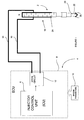
- a known piezoelectric injector 2 and its associated control system 4 are shown schematically in Figure 1 .
- the piezoelectric injector 2 is controlled by an injector control unit 6 (ICU) that forms an integral part of an engine control unit 8 (ECU).
- the ECU 8 monitors a plurality of engine parameters 10 and calculates an engine power requirement signal (not shown) which is input to the ICU 6.
- the ICU 6 calculates a required injection event sequence to provide the required power for the engine and operates an injector drive circuit 12 accordingly.
- the injector drive circuit 12 is connected to the injector 2 by way of first and second power supply leads 14, 16 and is operable to apply a differential voltage to the injector 2, via the leads 14, 16.
- the piezoelectric injector 2 includes a piezoelectric actuator 18 that is operable to control the position of an injector valve needle 20 relative to a valve needle seat 22.
- the piezoelectric actuator 18 includes a stack 24 of piezoelectric elements that expands and contracts in dependence on the differential voltage supplied by the drive circuit 12. The axial position, or 'lift', of the valve needle 20 is controlled by varying the differential voltage across the actuator 18.
- valve needle 20 is either caused to disengage the valve seat 22, in which case fuel is delivered into an associated combustion chamber (not shown) through a set of nozzle outlets 26, or is caused to engage the valve seat 22, in which case fuel delivery through the outlets 26 is prevented.
- a piezoelectrically controlled injector of the aforementioned type is described in the Applicant's European Patent Numbers EP 1174615 B and EP 0995901 B .
- the injector 2 is of the deenergise-to-inject type in which a reduction in the voltage across the actuator 18 initiates an injection event.
- the voltage across the actuator 18 is relatively high for the majority of its life (at least 90%). It has been identified that this may have a detrimental effect on injector service life as a correlation exists between the life of the piezoelectric actuator and the amount of time for which the actuator has a relatively high voltage across it.
- a method of operating an injector having a piezoelectric actuator for controlling movement of an injector valve needle comprising reducing the voltage across the actuator at a first rate in order to initiate an initial injection, increasing the voltage across the actuator in order to terminate the injection, and once the initial injection has terminated and before a subsequent injection is initiated, reducing the voltage across the actuator at a second rate, which is lower than the first rate, so as to de-energise the actuator but without initiating an injection.
- the method may be used to operate a piezoelectric fuel injector in which the actuator is coupled to the injector valve needle, for example through a hydraulic coupling, whereby extension and contraction of the actuator results in movement of the valve needle towards and away from a valve seating to control injection through injector outlets. Deenergisation of the actuator results in an extension of the actuator, which in turn causes the valve needle to lift to commence injection.
- the actuator In normal operation, in order to initiate the injection event the actuator is de-energised at a relatively high rate (i.e. the voltage across the actuator is reduced rapidly). To terminate the injection event the voltage across the actuator is increased. It has now been recognised that if, between the initial injection and a subsequent injection, the actuator is deenergised relatively slowly, (i.e. the voltage across the actuator is reduced slowly), an injection does not occur.
- the invention therefore allows the voltage across the actuator to be reduced between injections, so as to reduce the proportion of time for which the actuator experiences a relatively high voltage across it, but without initiating an injection. This benefits the life of the actuator and, hence, prolongs the service life of the injector.
- the voltage across the actuator may be increased after it has been reduced at the second rate, prior to a further subsequent injection. This ensures greater accuracy and repeatability of the control of injection events.
- the voltage across the actuator may be reduced at the second rate as a function of time which has elapsed since the initial injection. For a multiple injection sequence, for example, this can be used to ensure that all injections of the sequence (e.g. pilot, main, post) have completed between the actuator is discharged at the second rate. For example, the voltage across the actuator may be reduced at the second rate a predetermined time after the initial injection.
- the initial injection is an initial injection of an injection sequence and the subsequent injection is a subsequent injection of the same injection sequence. Therefore, the initial injection may be a pilot injection of the injection sequence and the subsequent injection may be a main injection of the same injection sequence.
- the initial injection may be a pilot injection of the injection sequence and the subsequent injection may be a further pilot injection of the same injection sequence.
- the initial injection is a main injection of a first sequence and the subsequent injection is a main injection of a second, later sequence. In this case it is much more desirable to re-establish the initial high voltage across the actuator before the subsequent injection is initiated.
- the method may be used to reduce the voltage across the actuator at the second rate as a function of the voltage across the actuator.
- the method may be implemented in a number of ways.
- the method may include reducing in a passive manner the voltage across the actuator at the second rate through a resistance associated with the injector (e.g. through a resistance across terminals of the actuator).
- the method may be implemented by reducing in an active manner the voltage across the actuator at the second rate e.g. under the control of an engine control means. It may be preferable to reduce the voltage actively, by means of the engine control means, as this affords a greater degree of control over injection and also avoids the need for additional hardware components in the form of resistive components.
- a drive circuit for an injector having a piezoelectric actuator for controlling movement of an injector valve needle comprising primary discharge means for reducing the voltage across the actuator at a first rate in order to initiate an initial injection, means for increasing the voltage across the actuator in order to terminate the injection, and secondary discharge means for reducing the voltage across the actuator at a second rate, which is lower than the first rate, once the initial injection has terminated and before a subsequent injection is initiated, so as to de-energise the actuator but without initiating an injection.
- the primary discharge means for reducing the voltage across the actuator at the first rate includes a switching circuit comprising a discharge switch for controlling discharging of the actuator through an inductive circuit.
- the secondary discharge means for reducing the voltage across the actuator at the second rate includes an engine control means for controlling in an active manner the discharging of the injector through the inductive circuit.
- the secondary discharge means for reducing the voltage across the actuator at the second rate includes a resistor connected across the actuator.
- aspects of the invention include a computer program product comprising at least one computer program software portion which, when executed in an executing environment, is operable to implement the method of the first aspect of the invention, a data storage medium having the or each computer software portion stored thereon and a microcomputer provided with said data storage medium.
- Figure 1 is a schematic representation of a known piezoelectric injector 2 and its associated control system.
- the method of the present invention is applicable to a piezoelectric fuel injector of the type described with reference to Figure 1 .
- the invention is applicable to a piezoelectric fuel injector of the type having a piezoelectric actuator coupled to a valve needle via a coupling including a hydraulic amplifier, for example as described in the Applicant's European Patents EP 1174615 B and EP 0995901B .
- the method is implemented in an engine control unit 8, such as that shown in Figure 1 , including the injector control unit (ICU) 6 and the drive circuit 12.
- the drive circuit differs from that shown in Figure 1 , as will be described in further detail below.
- the injector drive circuit 12 causes the differential voltage across the actuator 18 to transition from a high level (typically 200 V) at which no fuel delivery occurs, to a relatively low level (typically between +40V and -30V), which causes the actuator 18 to contract, thus lifting the valve needle 20 away from the valve needle seat 22 to permit fuel delivery through the outlets 26.
- the injector is operable to deliver one or more injections of fuel within a single injection event.
- the injection event may include one or more so-called 'pre-' or 'pilot' injections, a main injection, and one or more 'post' injections. In general, it is preferable to have several such injections within an injection sequence to increase combustion efficiency of the engine.
- the drive circuit of the ECU 8 is shown in more detail to include a switching circuit 30 in conjunction with an injector bank circuit 32 comprising first and second injectors, 34 and 36 respectively.
- injector bank circuit 32 comprising first and second injectors, 34 and 36 respectively.
- Each of the injectors 34, 36 of the injector bank circuit 32 is of the type shown in Figure 1 , having a respective piezoelectric actuator.
- the switching circuit 30 includes three input voltage rails: a high voltage rail V HI (typically 255 V), a mid voltage rail V MID (typically 55 V), and a ground rail GND.
- the switching circuit 30 also includes a high side voltage output V1 and a low side voltage output V2 and is operable to connect the high side voltage output V1 to either the high voltage rail V HI or the ground rail GND, through an inductor L, by means of first and second switch means Q1, Q2.
- the first switch means shall be referred to as the discharge switch Q1 and the second switch means shall be referred to as the charge switch Q2.
- a first diode D Q1 is connected across the discharge switch Q1 and a second diode is connected across the charge switch Q2.
- the switching circuit 30 is also provided with a diode D1 that connects the high side voltage output V1 to the high voltage rail V HI .
- the diode D1 is oriented to permit current to flow from the high side voltage output V1 to the high voltage rail V HI but to prevent current flow from the high voltage rail V HI to the high side voltage output V1.
- the injector bank circuit 32 comprises first and second branches 38, 40, each of which is connected in parallel between the high side voltage output V1 and the low side voltage output V2 of the switching circuit 30.
- the high side voltage output V1 of the switching circuit 30 is also a high side voltage input to the injector bank circuit 32 and the low side voltage output V2 of the switching circuit 30 is a low side voltage input to the bank circuit 32.
- the first branch 38 of the injector bank circuit 32 contains the first injector 34 and the second branch 40 contains the second injector 36.
- Each branch 38, 40 also includes an associated injector select switch QS1, QS2 by which means the respective one of the injectors, 34 or 36, can be selected for operation, as will be described later.
- Each of the injectors 34, 36 has an associated resistor, R1, R2, connected across it.
- each resistor R1, R2 may be connected across terminals of the actuator of the injector (i.e. actuator 18 in Figure 1 ) or may be incorporated within the stack structure of the actuator of the injector, as described in the Applicant's co-pending European patent application 05257559.4 .
- each resistor has a value of between 300 and 500 Ohms.
- the optimum value of the resistors R1, R2 is selected to be a compromise between a relatively higher value required to reduce the power dissipated in the resistor and a relatively lower value required to ensure that, between injections, the voltage across the injector is reduced to a satisfactory level within a reasonable time period, as discussed further below.
- first and second injectors 34, 36 are shown as integral to the injector bank circuit 32, in practice the other components of the injector bank circuit 32 would be remote from the injectors 34, 36 and connected thereto by way of power supply leads.
- each injector 34, 36 is considered electrically equivalent to a capacitor, the voltage difference between the high and low side voltage outputs, V1, V2, determining the amount of electrical charge stored by the actuator (i.e. the voltage across the actuator) and, thus, the lift position of the valve needle of the injector.
- the discharge switch of the switching circuit 30, when activated, connects the high side voltage output V1 to the ground rail GND via the inductor L. Therefore, charge from the actuator of the selected injector (assume the first injector 34 is the selected injector) is permitted to flow from the injector 34, through the inductor L and discharge switch Q1 to the ground rail GND, thereby serving to discharge the selected injector 34 during an injector discharge phase.
- the diode D Q2 connected across the charge switch Q2 is oriented to permit current to flow from the inductor L to the high voltage rail V HI when the discharge switch Q1 is deactivated, thus guarding against voltage peaks across the inductor L.
- the charge switch Q2 when activated, connects the high side voltage output V1 to the high voltage rail V HI via the inductor L.
- activating the charge switch Q2 causes charge to flow from the high voltage rail V HI , through the charge switch Q2 and the inductor L, and into the first injector 34, during an injector charge phase, until an equilibrium voltage is reached (the voltage due to charge stored by the actuator of the injector 34 equals the voltage difference between the high side voltage output V1 and the low side voltage output V2).
- the diode D Q1 connected across the discharge switch Q1 is oriented to permit current to flow from the ground rail GND through the inductor L to the high side voltage output V1 when the charge switch Q2 is deactivated, thus guarding against voltage peaks across the inductor L.
- the inductor L constitutes a bidirectional current path since current flows in a first direction through the inductor L during the injector discharge phase and in an opposite direction through the inductor L during the injector charge phase.
- the low side voltage output V2 of the injector bank circuit 32 is connected to the mid voltage rail V MID via a voltage sense resistor 44.
- a current sensing and comparator means 46 (hereinafter referred to as the comparator module) is connected in parallel with the sense resistor 44 and is operable to monitor the current flowing through the resistor 44.
- the comparator module 46 outputs a control signal, Q CONTROL , which controls the activation status of the discharge switch Q1 and the charge switch Q2 so as to regulate the peak current flowing from, or to, the selected injector 34.
- the comparator module 46 controls the activation status of the discharge and charge switches Q1 and Q2 to 'chop' the injector current between maximum and minimum current limits and achieve a predetermined average charge or discharge current level referred to as the 'current set point'.
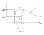
- Figure 3 shows a typical voltage trace for the first injector 34 for an injection sequence comprising a single injection 42 of fuel.
- the operation of the drive circuit 12 during a discharge phase, followed by a charge phase, in order to achieve the single injection 42 shown in Figure 3 will now be described.
- the ICU 6 selects the injector that it is required to inject by activating the appropriate injector select switch QS1 or QS2.
- the selected injector is the first injector 34.
- the ICU 6 initiates the discharge phase by enabling the discharge switch Q1 so as to cause the first injector 34 to discharge at a first discharge rate, RT1.
- the comparator module 46 outputs the signal Q CONTROL to deactivate and reactivate, repeatedly, the discharge switch Q1 such that the current remains within predetermined limits.
- a predetermined average discharge current level (the current set point) is therefore maintained through the first injector 34.
- the ICU 6 applies the predetermined average discharge current level for a period of time (from T 0 to T 1 ) that is sufficient to transfer a predetermined amount of charge from the first injector 34, hence initiating an injection.
- the timing of the discharge phase is read from a timing map that relates discharge phase time against fuel delivery volume.
- the actuator discharges at a first rate indicated by RT1.
- the ICU 6 deactivates the first injector select switch QS1 and disables the discharge switch Q1, thus terminating the control signal Q CONTROL , to prevent the first injector 34 discharging further.
- the ICU 6 maintains the first injector 34 at the discharged voltage level V DISCHARGE for a predetermined dwell period, T 1 to T 2 , for which the injector valve needle is held open to perform the injection.
- the ICU 6 activates the charge switch Q2, and deactivates the discharge switch S1, in order to start the injector charge phase so as to terminate injection.
- the high side voltage output V1 of the switching circuit 30 is connected to the high voltage rail V HI and charge begins to transfer onto the first injector 34.
- the comparator module 46 monitors the current flowing through the sense resistor 44 and controls the activation status of the charge switch Q2, via the control signal Q CONTROL , to ensure a predetermined average charging current level.
- the ICU 6 applies the predetermined average charging current level to the first injector 34 for a period of time that is sufficient to transfer a predetermined amount of charge onto the injector 34, hence terminating the injection.
- the ICU 6 disables the charge switch Q2 and waits for the ECU 8 to command a subsequent injection.
- the injector select switch QS1 and the charge switch Q1 are deactivated. Due to the presence of the resistor R1 across the first injector 34, the charge on the actuator of the first injector 34 will slowly discharge across the terminals of the actuator, thereby causing the voltage across the injector to decay at a second rate RT2.
- the value of the resistor R1 is selected to ensure that the rate of discharge RT2 of the voltage across the first injector 34 at the end of the injection is insufficient to cause a subsequent injection of fuel. This is possible because, if the actuator is caused to extend relatively slowly by discharging at a relatively low rate, it does not cause any corresponding movement of the injector valve needle due to the arrangement of the hydraulic coupling between the actuator and the valve needle. With a resistor R1 across the first injector 34 having a resistance of between 300 and 500 Ohms, typically the injector will discharge to V DISCHARGE over a time period of about 10 to 20 ms.
- V CHARGE Prior to a subsequent injection being demanded by the ECU 8, the high differential voltage V CHARGE is re-established across the first injector 34 (this is not illustrated in Figure 3 ).
- the high voltage, V CHARGE is re-established across the injector 34 by reselecting the first injector 34 by activation of the first injector select switch QS1 and carrying out the charging steps used to terminate injection, as described previously. Typically, this re-charge process will occur a few milliseconds prior to the subsequent injection.
- the injector 34 is ready to perform a subsequent injection demanded by the ECU 8.
- the benefit of having discharged the first injector 34 slowly at the end of the initial injection is that the actuator of the injector 34 experiences the high voltage level across it for a much reduced period of time compared to conventional operating methods whereby the injector remains charged to the high voltage level between injections.
- the method of the present invention therefore increases the service life of the actuator and, hence, increases the service life of the injector.
- the aforementioned method may be applied to any of the injectors of the engine, for example the second injector 36 of the injector bank 32, in a similar manner and to similar advantage.
- the resistors R1 and R2 provided across the injectors 34, 36 may be removed and, instead, the discharge of the injector 34, 36 at the end of an injection, and prior to a subsequent injection, may be controlled by means of the ECU 8.
- discharge of the injector 34, 36 at the end of an injection is controlled actively by the ECU 8, rather than passively by relying on the resistors R1, R2.
- the injector select switch QS1 is selected again (if not already selected) and a discharge phase is initiated, at a second discharge rate RT2, by activating the discharge switch Q1.
- the comparator module 46 and the discharge switch Q1 are operated by the ECU as described previously such that the current remains within predetermined limits and a predetermined average discharge current level is maintained through the first injector 34.
- the resistors R1, R2 are maintained in the injector bank circuit 32 together with additional electrical components (not shown) to control the resistors, rather than relying solely on the ECU to perform this function.
- the additional electrical components may include a means for sensing the voltage across the actuator of the injector and for adjusting the rate of discharge of the actuator as a function of the voltage across the actuator.
- the additional electrical components may include a means for discharging the actuator as a function of the time that has elapsed since the end of the last injection. In practice it would be preferable to make use of the ECU to control the discharge between injections, either in software or by controlling the resistors R1, R2, as this would not require the additional hardware of the electrical components.
- an injection sequence comprising a number of separate injections of fuel.
- Such an injection sequence is shown in Figure 4 , including a first pilot injection of fuel 50, followed by a second pilot injection of fuel 52, followed by a main injection of fuel 54.
- this may be achieved, for example, by maintaining the injector select switch of the selected injector in an activated state for the whole injection sequence i.e. for both of the pilot injections 50, 52 and for the main injection 54. With the injector selected, the injector remains connected to the supply voltage so that, although current flows through the discharge resistor R1 or R2, this is compensated by the current flow from the supply voltage. This is the effect shown in Figure 4 , where there is no discharge of the injector between the first pilot injection 50 and the second pilot injection 52, and between the second pilot injection 52 and the main injection 54.
- the injector select switch in an activated state throughout the injection sequence.
- the injector select switch deactivated between injections (i.e. between the first pilot and the second pilot, and between the second pilot and the main)
- the voltage does not drop significantly before the start of the subsequent injection of the sequence and so performance is not compromised.
- the injector discharges at a relatively low rate (not indicated in Figure 4 ), which is much less than the initial rate of discharge RT1, so that the voltage has not dropped significantly at the time when the second pilot injection 52 occurs.
- the rate of discharge following the second pilot injection 52 is also relatively low so that the voltage has not dropped significantly at the time when the main injection of fuel 54 is required.
- the ECU 8 may be configured to modulate the rate of voltage discharge across the selected injector as a function of time since the start of the injection sequence, rather than relying on the use of the resistors R1, R2.
- the injector is discharged at the first relatively high rate, RT1 (i.e. as described previously for the injection 42 in Figure 3 ).
- the ECU 8 then controls the voltage across the injector so that it is increased to terminate the first pilot injection 50. Once the first pilot injection has terminated, the injector remains at the relatively high level until the second pilot injection 52 is initiated.
- the ECU 8 controls the voltage across the injector to remain high until the main injection 54 is initiated. Following the main injection 54, the ECU 8 reduces the voltage across the injector at the second rate RT3, which is considerably lower than the rate RT1 required for an injection.
- the ECU 8 could be used to discharge the injector between injections of a sequence at a relatively low rate (e.g. between the first pilot injection and the second pilot injection, and between the second pilot injection and the main injection).
- the required rates of discharge may be predetermined and stored in a look-up table of the ECU 8. If time permits, the injector may be recharged between the first and second pilot injections and/or between the second pilot injection and the main injection.
- an initial rate of discharge may be applied to the injector for a fixed period of time after the first pilot injection has started and, once this fixed period of time has elapsed, a second, higher rate of discharge may be applied to the injector.
- the fixed period of time is set to ensure all injections of the injection sequence have taken place (e.g. the pilot injections 50, 52 and the main injection 54), before the second, lower rate of discharge (e.g. RT3) is applied.
- the ECU 8 may adjust the rate of discharge according to the voltage across the injector.
- the advantage is achieved that voltage across the actuator of an injector is reduced when it is not injecting so that, overall, the injector spends a considerably reduced amount of time in a fully charged state, therefore prolonging its service life.
Landscapes
- Engineering & Computer Science (AREA)
- Chemical & Material Sciences (AREA)
- Combustion & Propulsion (AREA)
- Mechanical Engineering (AREA)
- General Engineering & Computer Science (AREA)
- Fuel-Injection Apparatus (AREA)
- Electrical Control Of Air Or Fuel Supplied To Internal-Combustion Engine (AREA)
- Electrically Driven Valve-Operating Means (AREA)
Abstract
Description
- The invention relates to a method of operating a piezoelectric actuator. More specifically, the invention relates to a method of operating a piezoelectrically actuated fuel injector in order to improve injector life. The invention also relates to a drive circuit for implementing the method of the invention.
- In a direct injection internal combustion engine, a fuel injector is provided to deliver a charge of fuel to a combustion chamber prior to ignition. Typically, the fuel injector is mounted in a cylinder head with respect to the combustion chamber such that its tip protrudes slightly into the chamber in order to deliver a charge of fuel into the chamber.
- One type of fuel injector that is particularly suited for use in a direct injection engine is a so-called piezoelectric injector. Such an injector allows precise control of the timing and total delivery volume of a fuel injection event. This permits improved control over the combustion process which is beneficial in terms of exhaust emissions.
- A known
piezoelectric injector 2 and its associatedcontrol system 4 are shown schematically inFigure 1 . Thepiezoelectric injector 2 is controlled by an injector control unit 6 (ICU) that forms an integral part of an engine control unit 8 (ECU). TheECU 8 monitors a plurality ofengine parameters 10 and calculates an engine power requirement signal (not shown) which is input to theICU 6. In turn, the ICU 6 calculates a required injection event sequence to provide the required power for the engine and operates aninjector drive circuit 12 accordingly. Theinjector drive circuit 12 is connected to theinjector 2 by way of first and second power supply leads 14, 16 and is operable to apply a differential voltage to theinjector 2, via theleads - The
piezoelectric injector 2 includes apiezoelectric actuator 18 that is operable to control the position of aninjector valve needle 20 relative to avalve needle seat 22. Thepiezoelectric actuator 18 includes astack 24 of piezoelectric elements that expands and contracts in dependence on the differential voltage supplied by thedrive circuit 12. The axial position, or 'lift', of thevalve needle 20 is controlled by varying the differential voltage across theactuator 18. - By application of an appropriate voltage differential across the
actuator 18, thevalve needle 20 is either caused to disengage thevalve seat 22, in which case fuel is delivered into an associated combustion chamber (not shown) through a set ofnozzle outlets 26, or is caused to engage thevalve seat 22, in which case fuel delivery through theoutlets 26 is prevented. - A piezoelectrically controlled injector of the aforementioned type is described in the Applicant's European Patent Numbers
EP 1174615 B andEP 0995901 B . Theinjector 2 is of the deenergise-to-inject type in which a reduction in the voltage across theactuator 18 initiates an injection event. As an injector spends the majority of its life in a non-injecting state, in injectors of the deenergise-to-inject type the voltage across theactuator 18 is relatively high for the majority of its life (at least 90%). It has been identified that this may have a detrimental effect on injector service life as a correlation exists between the life of the piezoelectric actuator and the amount of time for which the actuator has a relatively high voltage across it. - It is an object of the present invention to provide an improved method of operating a piezoelectrically actuated fuel injector which alleviates the aforementioned problem.
- According to a first aspect of the present invention, there is provided a method of operating an injector having a piezoelectric actuator for controlling movement of an injector valve needle, the method comprising reducing the voltage across the actuator at a first rate in order to initiate an initial injection, increasing the voltage across the actuator in order to terminate the injection, and once the initial injection has terminated and before a subsequent injection is initiated, reducing the voltage across the actuator at a second rate, which is lower than the first rate, so as to de-energise the actuator but without initiating an injection.
- The method may be used to operate a piezoelectric fuel injector in which the actuator is coupled to the injector valve needle, for example through a hydraulic coupling, whereby extension and contraction of the actuator results in movement of the valve needle towards and away from a valve seating to control injection through injector outlets. Deenergisation of the actuator results in an extension of the actuator, which in turn causes the valve needle to lift to commence injection.
- In normal operation, in order to initiate the injection event the actuator is de-energised at a relatively high rate (i.e. the voltage across the actuator is reduced rapidly). To terminate the injection event the voltage across the actuator is increased. It has now been recognised that if, between the initial injection and a subsequent injection, the actuator is deenergised relatively slowly, (i.e. the voltage across the actuator is reduced slowly), an injection does not occur. The invention therefore allows the voltage across the actuator to be reduced between injections, so as to reduce the proportion of time for which the actuator experiences a relatively high voltage across it, but without initiating an injection. This benefits the life of the actuator and, hence, prolongs the service life of the injector.
- In one embodiment of the invention, the voltage across the actuator may be increased after it has been reduced at the second rate, prior to a further subsequent injection. This ensures greater accuracy and repeatability of the control of injection events.
- The voltage across the actuator may be reduced at the second rate as a function of time which has elapsed since the initial injection. For a multiple injection sequence, for example, this can be used to ensure that all injections of the sequence (e.g. pilot, main, post) have completed between the actuator is discharged at the second rate. For example, the voltage across the actuator may be reduced at the second rate a predetermined time after the initial injection.
- In one particular example, the initial injection is an initial injection of an injection sequence and the subsequent injection is a subsequent injection of the same injection sequence. Therefore, the initial injection may be a pilot injection of the injection sequence and the subsequent injection may be a main injection of the same injection sequence.
- Alternatively, the initial injection may be a pilot injection of the injection sequence and the subsequent injection may be a further pilot injection of the same injection sequence.
- In a further alternative, the initial injection is a main injection of a first sequence and the subsequent injection is a main injection of a second, later sequence. In this case it is much more desirable to re-establish the initial high voltage across the actuator before the subsequent injection is initiated.
- In another embodiment, the method may be used to reduce the voltage across the actuator at the second rate as a function of the voltage across the actuator.
- The method may be implemented in a number of ways. For example, the method may include reducing in a passive manner the voltage across the actuator at the second rate through a resistance associated with the injector (e.g. through a resistance across terminals of the actuator).
- Alternatively the method may be implemented by reducing in an active manner the voltage across the actuator at the second rate e.g. under the control of an engine control means. It may be preferable to reduce the voltage actively, by means of the engine control means, as this affords a greater degree of control over injection and also avoids the need for additional hardware components in the form of resistive components.
- According to a second aspect of the invention, there is provided a drive circuit for an injector having a piezoelectric actuator for controlling movement of an injector valve needle. The drive circuit comprises primary discharge means for reducing the voltage across the actuator at a first rate in order to initiate an initial injection, means for increasing the voltage across the actuator in order to terminate the injection, and secondary discharge means for reducing the voltage across the actuator at a second rate, which is lower than the first rate, once the initial injection has terminated and before a subsequent injection is initiated, so as to de-energise the actuator but without initiating an injection.
- In one embodiment, the primary discharge means for reducing the voltage across the actuator at the first rate includes a switching circuit comprising a discharge switch for controlling discharging of the actuator through an inductive circuit.
- In addition, the secondary discharge means for reducing the voltage across the actuator at the second rate includes an engine control means for controlling in an active manner the discharging of the injector through the inductive circuit.
- Alternatively, or in addition, the secondary discharge means for reducing the voltage across the actuator at the second rate includes a resistor connected across the actuator.
- Other aspects of the invention include a computer program product comprising at least one computer program software portion which, when executed in an executing environment, is operable to implement the method of the first aspect of the invention, a data storage medium having the or each computer software portion stored thereon and a microcomputer provided with said data storage medium.
- It will be appreciated that aspects of the method of the first aspect of the invention may be incorporated within the drive circuit of the second aspect of the invention, alone or in appropriate combination.
- Reference has already been made to
Figure 1 which is a schematic representation of a knownpiezoelectric injector 2 and its associated control system. - In order that it may be more readily understood, the invention will now be described with reference also to the following figures, in which:
-
Figure 2 is a circuit diagram of an injector drive circuit modified in accordance with the present invention, -
Figure 3 is a schematic graph of voltage against time for an injection sequence having a single injection of fuel and implemented using the injector drive circuit inFigure 2 , and -
Figure 4 is a schematic graph of voltage against time for an injection sequence having a pilot injection of fuel, followed by a main injection of fuel, followed by a post injection of fuel, as implemented in an alternative embodiment of the present invention. - The method of the present invention is applicable to a piezoelectric fuel injector of the type described with reference to
Figure 1 . In particular, the invention is applicable to a piezoelectric fuel injector of the type having a piezoelectric actuator coupled to a valve needle via a coupling including a hydraulic amplifier, for example as described in the Applicant's European PatentsEP 1174615 B andEP 0995901B . - The method is implemented in an
engine control unit 8, such as that shown inFigure 1 , including the injector control unit (ICU) 6 and thedrive circuit 12. In a first embodiment of the invention the drive circuit differs from that shown inFigure 1 , as will be described in further detail below. - In order to initiate an injection, the
injector drive circuit 12 causes the differential voltage across theactuator 18 to transition from a high level (typically 200 V) at which no fuel delivery occurs, to a relatively low level (typically between +40V and -30V), which causes theactuator 18 to contract, thus lifting thevalve needle 20 away from thevalve needle seat 22 to permit fuel delivery through theoutlets 26. The injector is operable to deliver one or more injections of fuel within a single injection event. For example, the injection event may include one or more so-called 'pre-' or 'pilot' injections, a main injection, and one or more 'post' injections. In general, it is preferable to have several such injections within an injection sequence to increase combustion efficiency of the engine. - It should be appreciated that although only one injector is shown in
Figure 1 , in practice several fuel injectors would be provided under the collective control of theICU 6 and thedrive circuit 12. Referring toFigure 2 , therefore, the drive circuit of theECU 8 is shown in more detail to include a switchingcircuit 30 in conjunction with aninjector bank circuit 32 comprising first and second injectors, 34 and 36 respectively. Each of theinjectors injector bank circuit 32 is of the type shown inFigure 1 , having a respective piezoelectric actuator. - The switching
circuit 30 includes three input voltage rails: a high voltage rail VHI (typically 255 V), a mid voltage rail VMID (typically 55 V), and a ground rail GND. The switchingcircuit 30 also includes a high side voltage output V1 and a low side voltage output V2 and is operable to connect the high side voltage output V1 to either the high voltage rail VHI or the ground rail GND, through an inductor L, by means of first and second switch means Q1, Q2. The first switch means shall be referred to as the discharge switch Q1 and the second switch means shall be referred to as the charge switch Q2. A first diode DQ1 is connected across the discharge switch Q1 and a second diode is connected across the charge switch Q2. - The switching
circuit 30 is also provided with a diode D1 that connects the high side voltage output V1 to the high voltage rail VHI. The diode D1 is oriented to permit current to flow from the high side voltage output V1 to the high voltage rail VHI but to prevent current flow from the high voltage rail VHI to the high side voltage output V1. - The
injector bank circuit 32 comprises first andsecond branches circuit 30. Thus, the high side voltage output V1 of the switchingcircuit 30 is also a high side voltage input to theinjector bank circuit 32 and the low side voltage output V2 of the switchingcircuit 30 is a low side voltage input to thebank circuit 32. Thefirst branch 38 of theinjector bank circuit 32 contains thefirst injector 34 and thesecond branch 40 contains thesecond injector 36. - Each
branch injectors Figure 1 ) or may be incorporated within the stack structure of the actuator of the injector, as described in the Applicant's co-pendingEuropean patent application 05257559.4 - Although the first and
second injectors injector bank circuit 32, in practice the other components of theinjector bank circuit 32 would be remote from theinjectors - The piezoelectric actuator of each
injector - In use, the discharge switch of the switching
circuit 30, when activated, connects the high side voltage output V1 to the ground rail GND via the inductor L. Therefore, charge from the actuator of the selected injector (assume thefirst injector 34 is the selected injector) is permitted to flow from theinjector 34, through the inductor L and discharge switch Q1 to the ground rail GND, thereby serving to discharge the selectedinjector 34 during an injector discharge phase. The diode DQ2 connected across the charge switch Q2 is oriented to permit current to flow from the inductor L to the high voltage rail VHI when the discharge switch Q1 is deactivated, thus guarding against voltage peaks across the inductor L. - In contrast, the charge switch Q2, when activated, connects the high side voltage output V1 to the high voltage rail VHI via the inductor L. In circumstances where the
first injector 34 is discharged, activating the charge switch Q2 causes charge to flow from the high voltage rail VHI, through the charge switch Q2 and the inductor L, and into thefirst injector 34, during an injector charge phase, until an equilibrium voltage is reached (the voltage due to charge stored by the actuator of theinjector 34 equals the voltage difference between the high side voltage output V1 and the low side voltage output V2). The diode DQ1 connected across the discharge switch Q1 is oriented to permit current to flow from the ground rail GND through the inductor L to the high side voltage output V1 when the charge switch Q2 is deactivated, thus guarding against voltage peaks across the inductor L. - From the foregoing description it is apparent that the inductor L constitutes a bidirectional current path since current flows in a first direction through the inductor L during the injector discharge phase and in an opposite direction through the inductor L during the injector charge phase.
- The low side voltage output V2 of the
injector bank circuit 32 is connected to the mid voltage rail VMID via avoltage sense resistor 44. A current sensing and comparator means 46 (hereinafter referred to as the comparator module) is connected in parallel with thesense resistor 44 and is operable to monitor the current flowing through theresistor 44. In response to the current flowing through theresistor 44, thecomparator module 46 outputs a control signal, QCONTROL, which controls the activation status of the discharge switch Q1 and the charge switch Q2 so as to regulate the peak current flowing from, or to, the selectedinjector 34. In effect, thecomparator module 46 controls the activation status of the discharge and charge switches Q1 and Q2 to 'chop' the injector current between maximum and minimum current limits and achieve a predetermined average charge or discharge current level referred to as the 'current set point'. By this means, a high degree of control is afforded over the amount of electrical charge that is transferred from the selected injector during the injector discharge phase and, conversely, to the selected injector during the injector charge phase. -
Figure 3 shows a typical voltage trace for thefirst injector 34 for an injection sequence comprising asingle injection 42 of fuel. The operation of thedrive circuit 12 during a discharge phase, followed by a charge phase, in order to achieve thesingle injection 42 shown inFigure 3 will now be described. - Initially, prior to time T0, the actuators of both
injectors ICU 6 is in a wait state awaiting an injection command signal from theECU 8. - Following receipt of the injection command from the
ECU 8, theICU 6 selects the injector that it is required to inject by activating the appropriate injector select switch QS1 or QS2. For the purpose of the following description, the selected injector is thefirst injector 34. At substantially the same time (i.e. at time T0 inFigure 3 ), theICU 6 initiates the discharge phase by enabling the discharge switch Q1 so as to cause thefirst injector 34 to discharge at a first discharge rate, RT1. Between T0 and T1 the current flow through thesense resistor 44 is sensed and thecomparator module 46 outputs the signal QCONTROL to deactivate and reactivate, repeatedly, the discharge switch Q1 such that the current remains within predetermined limits. A predetermined average discharge current level (the current set point) is therefore maintained through thefirst injector 34. - The
ICU 6 applies the predetermined average discharge current level for a period of time (from T0 to T1) that is sufficient to transfer a predetermined amount of charge from thefirst injector 34, hence initiating an injection. The timing of the discharge phase is read from a timing map that relates discharge phase time against fuel delivery volume. The actuator discharges at a first rate indicated by RT1. At time T1, theICU 6 deactivates the first injector select switch QS1 and disables the discharge switch Q1, thus terminating the control signal QCONTROL, to prevent thefirst injector 34 discharging further. Thus, during the time period T0 to T1 the voltage across the injector INJ1 drops from a charged voltage level VCHARGE (200V) to a discharged voltage level VDISCHARGE (-55V). This causes the actuator of thefirst injector 34 to contract and, thus, causes the valve needle of thefirst injector 34 to lift from its seat to commence the injection of fuel. - The
ICU 6 maintains thefirst injector 34 at the discharged voltage level VDISCHARGE for a predetermined dwell period, T1 to T2, for which the injector valve needle is held open to perform the injection. At the end of the dwell period, theICU 6 activates the charge switch Q2, and deactivates the discharge switch S1, in order to start the injector charge phase so as to terminate injection. With the charge switch Q2 activated and the discharge switch Q1 deactivated, the high side voltage output V1 of the switchingcircuit 30 is connected to the high voltage rail VHI and charge begins to transfer onto thefirst injector 34. - As the current flowing into the
first injector 34 increases, thecomparator module 46 monitors the current flowing through thesense resistor 44 and controls the activation status of the charge switch Q2, via the control signal QCONTROL, to ensure a predetermined average charging current level. Between time T2 and T3, theICU 6 applies the predetermined average charging current level to thefirst injector 34 for a period of time that is sufficient to transfer a predetermined amount of charge onto theinjector 34, hence terminating the injection. At time T3, theICU 6 disables the charge switch Q2 and waits for theECU 8 to command a subsequent injection. - At the end of the injection, the injector select switch QS1 and the charge switch Q1 are deactivated. Due to the presence of the resistor R1 across the
first injector 34, the charge on the actuator of thefirst injector 34 will slowly discharge across the terminals of the actuator, thereby causing the voltage across the injector to decay at a second rate RT2. The value of the resistor R1 is selected to ensure that the rate of discharge RT2 of the voltage across thefirst injector 34 at the end of the injection is insufficient to cause a subsequent injection of fuel. This is possible because, if the actuator is caused to extend relatively slowly by discharging at a relatively low rate, it does not cause any corresponding movement of the injector valve needle due to the arrangement of the hydraulic coupling between the actuator and the valve needle. With a resistor R1 across thefirst injector 34 having a resistance of between 300 and 500 Ohms, typically the injector will discharge to VDISCHARGE over a time period of about 10 to 20 ms. - Prior to a subsequent injection being demanded by the
ECU 8, the high differential voltage VCHARGE is re-established across the first injector 34 (this is not illustrated inFigure 3 ). The high voltage, VCHARGE, is re-established across theinjector 34 by reselecting thefirst injector 34 by activation of the first injector select switch QS1 and carrying out the charging steps used to terminate injection, as described previously. Typically, this re-charge process will occur a few milliseconds prior to the subsequent injection. - Once the high voltage level, VCHARGE, is re-established across the
first injector 34, theinjector 34 is ready to perform a subsequent injection demanded by theECU 8. However, the benefit of having discharged thefirst injector 34 slowly at the end of the initial injection is that the actuator of theinjector 34 experiences the high voltage level across it for a much reduced period of time compared to conventional operating methods whereby the injector remains charged to the high voltage level between injections. The method of the present invention therefore increases the service life of the actuator and, hence, increases the service life of the injector. - The aforementioned method may be applied to any of the injectors of the engine, for example the
second injector 36 of theinjector bank 32, in a similar manner and to similar advantage. - In an alternative embodiment to that described previously (not shown), the resistors R1 and R2 provided across the
injectors injector ECU 8. In this case discharge of theinjector ECU 8, rather than passively by relying on the resistors R1, R2. At the end of an injection for thefirst injector 34, the injector select switch QS1 is selected again (if not already selected) and a discharge phase is initiated, at a second discharge rate RT2, by activating the discharge switch Q1. In order to control the discharge rate RT2 during this secondary discharge phase, thecomparator module 46 and the discharge switch Q1 are operated by the ECU as described previously such that the current remains within predetermined limits and a predetermined average discharge current level is maintained through thefirst injector 34. As mentioned previously, it is essential that ECU controls the discharge switch Q1 in such a way that the second discharge rate RT2 is slow enough to ensure that the injector needle is not caused to open during this secondary discharge. - In a further alternative embodiment, the resistors R1, R2 are maintained in the
injector bank circuit 32 together with additional electrical components (not shown) to control the resistors, rather than relying solely on the ECU to perform this function. The additional electrical components may include a means for sensing the voltage across the actuator of the injector and for adjusting the rate of discharge of the actuator as a function of the voltage across the actuator. Alternatively, the additional electrical components may include a means for discharging the actuator as a function of the time that has elapsed since the end of the last injection. In practice it would be preferable to make use of the ECU to control the discharge between injections, either in software or by controlling the resistors R1, R2, as this would not require the additional hardware of the electrical components. - In many circumstances it is desirable to have an injection sequence comprising a number of separate injections of fuel. Such an injection sequence is shown in
Figure 4 , including a first pilot injection offuel 50, followed by a second pilot injection offuel 52, followed by a main injection offuel 54. In some circumstances it may be important to ensure that, prior to the main injection following the second pilot injection, the voltage across the actuator of the selected injector is re-established to a sufficiently high level before the later injection is carried out. The same applies to the second pilot injection following the first pilot injection. - In the circuit of
Figure 2 , this may be achieved, for example, by maintaining the injector select switch of the selected injector in an activated state for the whole injection sequence i.e. for both of thepilot injections main injection 54. With the injector selected, the injector remains connected to the supply voltage so that, although current flows through the discharge resistor R1 or R2, this is compensated by the current flow from the supply voltage. This is the effect shown inFigure 4 , where there is no discharge of the injector between thefirst pilot injection 50 and thesecond pilot injection 52, and between thesecond pilot injection 52 and themain injection 54. - In some circumstances it may not be desirable to maintain the injector select switch in an activated state throughout the injection sequence. However, even with the injector select switch deactivated between injections (i.e. between the first pilot and the second pilot, and between the second pilot and the main), the voltage does not drop significantly before the start of the subsequent injection of the sequence and so performance is not compromised. Once the first pilot injection has terminated, the injector discharges at a relatively low rate (not indicated in
Figure 4 ), which is much less than the initial rate of discharge RT1, so that the voltage has not dropped significantly at the time when thesecond pilot injection 52 occurs. Likewise, the rate of discharge following thesecond pilot injection 52 is also relatively low so that the voltage has not dropped significantly at the time when the main injection offuel 54 is required. - In a modification to the aforementioned method, which accommodates an injection sequence comprising more than one close-spaced injections of fuel (e.g. pilot, pilot, main), the
ECU 8 may be configured to modulate the rate of voltage discharge across the selected injector as a function of time since the start of the injection sequence, rather than relying on the use of the resistors R1, R2. The injector is discharged at the first relatively high rate, RT1 (i.e. as described previously for theinjection 42 inFigure 3 ). TheECU 8 then controls the voltage across the injector so that it is increased to terminate thefirst pilot injection 50. Once the first pilot injection has terminated, the injector remains at the relatively high level until thesecond pilot injection 52 is initiated. As before, once the second pilot injection has terminated, theECU 8 controls the voltage across the injector to remain high until themain injection 54 is initiated. Following themain injection 54, theECU 8 reduces the voltage across the injector at the second rate RT3, which is considerably lower than the rate RT1 required for an injection. - If required, the
ECU 8 could be used to discharge the injector between injections of a sequence at a relatively low rate (e.g. between the first pilot injection and the second pilot injection, and between the second pilot injection and the main injection). The required rates of discharge may be predetermined and stored in a look-up table of theECU 8. If time permits, the injector may be recharged between the first and second pilot injections and/or between the second pilot injection and the main injection. - By way of further example, if the
ECU 8 demands an injection strategy comprising more than one injection of fuel, an initial rate of discharge may be applied to the injector for a fixed period of time after the first pilot injection has started and, once this fixed period of time has elapsed, a second, higher rate of discharge may be applied to the injector. The fixed period of time is set to ensure all injections of the injection sequence have taken place (e.g. thepilot injections - In an alternative implementation, the
ECU 8 may adjust the rate of discharge according to the voltage across the injector. - In any of the aforementioned embodiments, the advantage is achieved that voltage across the actuator of an injector is reduced when it is not injecting so that, overall, the injector spends a considerably reduced amount of time in a fully charged state, therefore prolonging its service life.
Claims (19)
- A method of operating an injector (34, 36) having a piezoelectric actuator for controlling movement of an injector valve needle, the method comprising:reducing the voltage across the actuator at a first rate (RT1) in order to initiate an initial injection (42; 50; 52),increasing the voltage across the actuator in order to terminate the injection, andonce the initial injection (42; 50; 52) has terminated and before a subsequent injection is initiated, reducing the voltage across the actuator at a second rate (RT2; RT3), which is lower than the first rate (RT1), so as to de-energise the actuator but without initiating an injection.
- The method as claimed in claim 1, further comprising increasing the voltage across the actuator after it has been reduced at the second rate (RT2; RT3), prior to a further subsequent injection.
- The method as claimed in claim 1 or claim 2, including reducing the voltage across the actuator at the second rate (RT2; RT3) as a function of time which has elapsed since the initial injection (50).
- The method as claimed in claim 3, including reducing the voltage across the actuator at the second rate (RT2; RT3) a predetermined time after the initial injection (50).
- The method as claimed in claim 4, wherein the initial injection is an initial injection (50; 52) of an injection sequence and the subsequent injection is a subsequent injection (52; 54) of the same injection sequence.
- The method as claimed in claim 5, wherein the initial injection is a pilot injection (52) of the injection sequence and the subsequent injection is a main injection (54) of the same injection sequence.
- The method as claimed in claim 5, wherein the initial injection is a pilot injection (50) of the injection sequence and the subsequent injection is a further pilot injection (52) of the same injection sequence.
- The method as claimed in any one of claims 5 to 7, wherein the predetermined time is selected to be greater than the time period for the injection sequence to complete.
- The method as claimed in claim 1 or claim 2, including reducing the voltage across the actuator at the second rate (RT2; RT3) as a function of the voltage across the actuator.
- The method as claimed in any one of claims 1 to 9, comprising reducing the voltage across the actuator at the second rate (RT2; RT3) through a resistance (R1, R2) associated with the injector.
- The method as claimed in claim 10, comprising reducing the voltage across the actuator at the second rate (RT2; RT3) through a resistance (R1, R2) across terminals of the actuator.
- The method as claimed in any one of claims 1 to 9, comprising reducing the voltage across the actuator at the second rate (RT2; RT3) actively under the control of an engine control means (8).
- A computer program product comprising at least one computer program software portion which, when executed in an executing environment, is operable to implement the method of any one of claims 1 to 12.
- A data storage medium having the or each computer software portion of claim 13 stored thereon.
- A microcomputer provided with the data storage medium of claim 14.
- A drive circuit for an injector (34, 36) comprising a piezoelectric actuator for controlling movement of an injector valve needle, the drive circuit comprising:primary discharge means (Q1) for reducing the voltage across the actuator at a first rate (RT1) in order to initiate an initial injection (42),means (Q2) for increasing the voltage across the actuator in order to terminate the injection, andsecondary discharge means (R1, R2) for reducing the voltage across the actuator at a second rate (RT2; RT3), which is lower than the first rate (RT1), once the initial injection (42) has terminated and before a subsequent injection is initiated, so as to deenergise the actuator but without initiating an injection.
- The drive circuit as claimed in claim 16, wherein the primary discharge means for reducing the voltage across the actuator at the first rate (RT1) includes a switching circuit (30) comprising a discharge switch (Q1) for controlling discharging of the actuator through an inductive circuit.
- The drive circuit as claimed in claim 17, wherein the secondary discharge means for reducing the voltage across the actuator at the second rate (RT2; RT3) includes an engine control means (8) for actively controlling discharging of the injector through the inductive circuit.
- The drive circuit as claimed in claim 17, wherein the secondary discharge means for reducing the voltage across the actuator at the second rate (RT2; RT3) includes a resistor (R1, R2) connected across the actuator.
Priority Applications (5)
| Application Number | Priority Date | Filing Date | Title |
|---|---|---|---|
| EP07250454A EP1956221B1 (en) | 2007-02-02 | 2007-02-02 | A method of operating a piezoelectric actuator |
| DE602007003554T DE602007003554D1 (en) | 2007-02-02 | 2007-02-02 | Method for operating a piezoelectric actuator |
| AT07250454T ATE450705T1 (en) | 2007-02-02 | 2007-02-02 | METHOD FOR OPERATING A PIEZOELECTRIC ACTUATOR |
| JP2008018519A JP2008190528A (en) | 2007-02-02 | 2008-01-30 | Method of operating piezoelectric actuator |
| US12/012,099 US7576473B2 (en) | 2007-02-02 | 2008-01-31 | Method of operating a piezoelectric actuator |
Applications Claiming Priority (1)
| Application Number | Priority Date | Filing Date | Title |
|---|---|---|---|
| EP07250454A EP1956221B1 (en) | 2007-02-02 | 2007-02-02 | A method of operating a piezoelectric actuator |
Publications (2)
| Publication Number | Publication Date |
|---|---|
| EP1956221A1 true EP1956221A1 (en) | 2008-08-13 |
| EP1956221B1 EP1956221B1 (en) | 2009-12-02 |
Family
ID=38318651
Family Applications (1)
| Application Number | Title | Priority Date | Filing Date |
|---|---|---|---|
| EP07250454A Not-in-force EP1956221B1 (en) | 2007-02-02 | 2007-02-02 | A method of operating a piezoelectric actuator |
Country Status (5)
| Country | Link |
|---|---|
| US (1) | US7576473B2 (en) |
| EP (1) | EP1956221B1 (en) |
| JP (1) | JP2008190528A (en) |
| AT (1) | ATE450705T1 (en) |
| DE (1) | DE602007003554D1 (en) |
Families Citing this family (4)
| Publication number | Priority date | Publication date | Assignee | Title |
|---|---|---|---|---|
| DE102006058744A1 (en) * | 2006-12-12 | 2008-06-19 | Robert Bosch Gmbh | Method for operating an injection valve |
| EP2037109B1 (en) * | 2007-09-14 | 2010-06-16 | Delphi Technologies Holding S.à.r.l. | Injection control system |
| DE102008027516B3 (en) * | 2008-06-10 | 2010-04-01 | Continental Automotive Gmbh | Method for injection quantity deviation detection and correction of an injection quantity and injection system |
| CN110360015B (en) * | 2019-07-02 | 2022-05-20 | 成都恩吉威汽车技术有限公司 | Dual-purpose fuel control system of GDI engine |
Citations (4)
| Publication number | Priority date | Publication date | Assignee | Title |
|---|---|---|---|---|
| GB2366664A (en) * | 2000-09-08 | 2002-03-13 | Delphi Tech Inc | Control method for a piezoelectric fuel injector |
| EP1400677A2 (en) * | 2002-09-23 | 2004-03-24 | Delphi Technologies, Inc. | Injector system |
| EP1628010A2 (en) * | 2004-08-18 | 2006-02-22 | Siemens Aktiengesellschaft | Method and circuit arrangement for driving a piezoelectric actuator |
| EP1746318A1 (en) * | 2005-07-22 | 2007-01-24 | Delphi Technologies, Inc. | Method and device for supervising and assessing the function of a piezoelectric actuator |
Family Cites Families (10)
| Publication number | Priority date | Publication date | Assignee | Title |
|---|---|---|---|---|
| DE19652809C1 (en) * | 1996-12-18 | 1998-06-10 | Siemens Ag | Method and device for controlling at least one capacitive actuator |
| JP2000023474A (en) * | 1998-07-01 | 2000-01-21 | Isuzu Motors Ltd | Piezoelectric actuator and fuel injection device using the same |
| ATE446590T1 (en) * | 2000-04-01 | 2009-11-15 | Bosch Gmbh Robert | METHOD AND DEVICE FOR CONTROLLING VOLTAGE AND VOLTAGE GRADIENTS FOR DRIVING A PIEZOELECTRIC ELEMENT |
| DE10035815A1 (en) * | 2000-07-22 | 2002-01-31 | Bosch Gmbh Robert | Injection valve control method |
| GB0104215D0 (en) * | 2001-02-21 | 2001-04-11 | Delphi Tech Inc | Control method |
| JP2003214302A (en) * | 2001-11-16 | 2003-07-30 | Ngk Insulators Ltd | Liquid fuel injection device |
| US6760212B2 (en) * | 2002-09-23 | 2004-07-06 | Delphi Technologies, Inc. | Piezoelectric injector drive circuit |
| US6912998B1 (en) * | 2004-03-10 | 2005-07-05 | Cummins Inc. | Piezoelectric fuel injection system with rate shape control and method of controlling same |
| US7681555B2 (en) * | 2006-05-23 | 2010-03-23 | Delphi Technologies, Inc. | Controller for a fuel injector and a method of operating a fuel injector |
| EP1860310B1 (en) * | 2006-05-23 | 2015-08-12 | Delphi International Operations Luxembourg S.à r.l. | Method of operating a fuel injector |
-
2007
- 2007-02-02 EP EP07250454A patent/EP1956221B1/en not_active Not-in-force
- 2007-02-02 DE DE602007003554T patent/DE602007003554D1/en not_active Expired - Fee Related
- 2007-02-02 AT AT07250454T patent/ATE450705T1/en not_active IP Right Cessation
-
2008
- 2008-01-30 JP JP2008018519A patent/JP2008190528A/en active Pending
- 2008-01-31 US US12/012,099 patent/US7576473B2/en not_active Expired - Fee Related
Patent Citations (4)
| Publication number | Priority date | Publication date | Assignee | Title |
|---|---|---|---|---|
| GB2366664A (en) * | 2000-09-08 | 2002-03-13 | Delphi Tech Inc | Control method for a piezoelectric fuel injector |
| EP1400677A2 (en) * | 2002-09-23 | 2004-03-24 | Delphi Technologies, Inc. | Injector system |
| EP1628010A2 (en) * | 2004-08-18 | 2006-02-22 | Siemens Aktiengesellschaft | Method and circuit arrangement for driving a piezoelectric actuator |
| EP1746318A1 (en) * | 2005-07-22 | 2007-01-24 | Delphi Technologies, Inc. | Method and device for supervising and assessing the function of a piezoelectric actuator |
Also Published As
| Publication number | Publication date |
|---|---|
| JP2008190528A (en) | 2008-08-21 |
| US20080184967A1 (en) | 2008-08-07 |
| ATE450705T1 (en) | 2009-12-15 |
| US7576473B2 (en) | 2009-08-18 |
| EP1956221B1 (en) | 2009-12-02 |
| DE602007003554D1 (en) | 2010-01-14 |
Similar Documents
| Publication | Publication Date | Title |
|---|---|---|
| EP1860309B1 (en) | Improvements relating to fuel injector control | |
| EP1860310B1 (en) | Method of operating a fuel injector | |
| US10648419B2 (en) | Fuel injection control device and fuel injection system | |
| EP1956221B1 (en) | A method of operating a piezoelectric actuator | |
| JP4787407B2 (en) | Method and apparatus for controlling at least one capacitive actuator | |
| JP4871364B2 (en) | Fuel injector and operation method thereof | |
| EP1400677B1 (en) | Injector system | |
| JP5795739B2 (en) | Improvements related to fuel injector control | |
| US20080087748A1 (en) | Method and Injection System for Injecting a Fluid | |
| EP2290211B1 (en) | Power supply arrangement for a fuel injector drive circuit | |
| JP3913687B2 (en) | Piezo actuator driving circuit and fuel injection device | |
| US20070273247A1 (en) | Controller for a fuel injector and a method of operating a fuel injector | |
| JP2003111448A (en) | Piezo actuator drive circuit | |
| US7732946B2 (en) | Current source, control device and method for operating said control device | |
| EP1860308A1 (en) | Method of operating a fuel injector | |
| JP2002371896A (en) | Injection control device for internal combustion engine | |
| EP1927742A1 (en) | A method of operating a piezoelectric device | |
| JP4626112B2 (en) | Piezoelectric discharge device | |
| EP1927741A1 (en) | A method of operating a piezoelectric device | |
| JP2591267B2 (en) | Fuel injection device for internal combustion engine | |
| JP4346806B2 (en) | Fuel injection device | |
| JP4803016B2 (en) | Fuel injection control device | |
| JP3777871B2 (en) | Injector drive device |
Legal Events
| Date | Code | Title | Description |
|---|---|---|---|
| PUAI | Public reference made under article 153(3) epc to a published international application that has entered the european phase |
Free format text: ORIGINAL CODE: 0009012 |
|
| AK | Designated contracting states |
Kind code of ref document: A1 Designated state(s): AT BE BG CH CY CZ DE DK EE ES FI FR GB GR HU IE IS IT LI LT LU LV MC NL PL PT RO SE SI SK TR |
|
| AX | Request for extension of the european patent |
Extension state: AL BA HR MK RS |
|
| 17P | Request for examination filed |
Effective date: 20080813 |
|
| AKX | Designation fees paid |
Designated state(s): AT BE BG CH CY CZ DE DK EE ES FI FR GB GR HU IE IS IT LI LT LU LV MC NL PL PT RO SE SI SK TR |
|
| GRAP | Despatch of communication of intention to grant a patent |
Free format text: ORIGINAL CODE: EPIDOSNIGR1 |
|
| GRAS | Grant fee paid |
Free format text: ORIGINAL CODE: EPIDOSNIGR3 |
|
| GRAA | (expected) grant |
Free format text: ORIGINAL CODE: 0009210 |
|
| AK | Designated contracting states |
Kind code of ref document: B1 Designated state(s): AT BE BG CH CY CZ DE DK EE ES FI FR GB GR HU IE IS IT LI LT LU LV MC NL PL PT RO SE SI SK TR |
|
| REG | Reference to a national code |
Ref country code: GB Ref legal event code: FG4D |
|
| REG | Reference to a national code |
Ref country code: CH Ref legal event code: EP |
|
| REG | Reference to a national code |
Ref country code: IE Ref legal event code: FG4D |
|
| REF | Corresponds to: |
Ref document number: 602007003554 Country of ref document: DE Date of ref document: 20100114 Kind code of ref document: P |
|
| RAP2 | Party data changed (patent owner data changed or rights of a patent transferred) |
Owner name: DELPHI TECHNOLOGIES HOLDING S.A.R.L. |
|
| REG | Reference to a national code |
Ref country code: NL Ref legal event code: VDEP Effective date: 20091202 |
|
| PG25 | Lapsed in a contracting state [announced via postgrant information from national office to epo] |
Ref country code: FI Free format text: LAPSE BECAUSE OF FAILURE TO SUBMIT A TRANSLATION OF THE DESCRIPTION OR TO PAY THE FEE WITHIN THE PRESCRIBED TIME-LIMIT Effective date: 20091202 Ref country code: SE Free format text: LAPSE BECAUSE OF FAILURE TO SUBMIT A TRANSLATION OF THE DESCRIPTION OR TO PAY THE FEE WITHIN THE PRESCRIBED TIME-LIMIT Effective date: 20091202 Ref country code: LT Free format text: LAPSE BECAUSE OF FAILURE TO SUBMIT A TRANSLATION OF THE DESCRIPTION OR TO PAY THE FEE WITHIN THE PRESCRIBED TIME-LIMIT Effective date: 20091202 |
|
| LTIE | Lt: invalidation of european patent or patent extension |
Effective date: 20091202 |
|
| PG25 | Lapsed in a contracting state [announced via postgrant information from national office to epo] |
Ref country code: PL Free format text: LAPSE BECAUSE OF FAILURE TO SUBMIT A TRANSLATION OF THE DESCRIPTION OR TO PAY THE FEE WITHIN THE PRESCRIBED TIME-LIMIT Effective date: 20091202 Ref country code: SI Free format text: LAPSE BECAUSE OF FAILURE TO SUBMIT A TRANSLATION OF THE DESCRIPTION OR TO PAY THE FEE WITHIN THE PRESCRIBED TIME-LIMIT Effective date: 20091202 Ref country code: LV Free format text: LAPSE BECAUSE OF FAILURE TO SUBMIT A TRANSLATION OF THE DESCRIPTION OR TO PAY THE FEE WITHIN THE PRESCRIBED TIME-LIMIT Effective date: 20091202 Ref country code: CY Free format text: LAPSE BECAUSE OF FAILURE TO SUBMIT A TRANSLATION OF THE DESCRIPTION OR TO PAY THE FEE WITHIN THE PRESCRIBED TIME-LIMIT Effective date: 20091202 |
|
| PG25 | Lapsed in a contracting state [announced via postgrant information from national office to epo] |
Ref country code: AT Free format text: LAPSE BECAUSE OF FAILURE TO SUBMIT A TRANSLATION OF THE DESCRIPTION OR TO PAY THE FEE WITHIN THE PRESCRIBED TIME-LIMIT Effective date: 20091202 |
|
| PG25 | Lapsed in a contracting state [announced via postgrant information from national office to epo] |
Ref country code: BG Free format text: LAPSE BECAUSE OF FAILURE TO SUBMIT A TRANSLATION OF THE DESCRIPTION OR TO PAY THE FEE WITHIN THE PRESCRIBED TIME-LIMIT Effective date: 20100302 Ref country code: ES Free format text: LAPSE BECAUSE OF FAILURE TO SUBMIT A TRANSLATION OF THE DESCRIPTION OR TO PAY THE FEE WITHIN THE PRESCRIBED TIME-LIMIT Effective date: 20100313 Ref country code: RO Free format text: LAPSE BECAUSE OF FAILURE TO SUBMIT A TRANSLATION OF THE DESCRIPTION OR TO PAY THE FEE WITHIN THE PRESCRIBED TIME-LIMIT Effective date: 20091202 Ref country code: IS Free format text: LAPSE BECAUSE OF FAILURE TO SUBMIT A TRANSLATION OF THE DESCRIPTION OR TO PAY THE FEE WITHIN THE PRESCRIBED TIME-LIMIT Effective date: 20100402 Ref country code: PT Free format text: LAPSE BECAUSE OF FAILURE TO SUBMIT A TRANSLATION OF THE DESCRIPTION OR TO PAY THE FEE WITHIN THE PRESCRIBED TIME-LIMIT Effective date: 20100402 Ref country code: NL Free format text: LAPSE BECAUSE OF FAILURE TO SUBMIT A TRANSLATION OF THE DESCRIPTION OR TO PAY THE FEE WITHIN THE PRESCRIBED TIME-LIMIT Effective date: 20091202 Ref country code: EE Free format text: LAPSE BECAUSE OF FAILURE TO SUBMIT A TRANSLATION OF THE DESCRIPTION OR TO PAY THE FEE WITHIN THE PRESCRIBED TIME-LIMIT Effective date: 20091202 |
|
| PG25 | Lapsed in a contracting state [announced via postgrant information from national office to epo] |
Ref country code: SK Free format text: LAPSE BECAUSE OF FAILURE TO SUBMIT A TRANSLATION OF THE DESCRIPTION OR TO PAY THE FEE WITHIN THE PRESCRIBED TIME-LIMIT Effective date: 20091202 Ref country code: CZ Free format text: LAPSE BECAUSE OF FAILURE TO SUBMIT A TRANSLATION OF THE DESCRIPTION OR TO PAY THE FEE WITHIN THE PRESCRIBED TIME-LIMIT Effective date: 20091202 Ref country code: BE Free format text: LAPSE BECAUSE OF FAILURE TO SUBMIT A TRANSLATION OF THE DESCRIPTION OR TO PAY THE FEE WITHIN THE PRESCRIBED TIME-LIMIT Effective date: 20091202 |
|
| PLBE | No opposition filed within time limit |
Free format text: ORIGINAL CODE: 0009261 |
|
| STAA | Information on the status of an ep patent application or granted ep patent |
Free format text: STATUS: NO OPPOSITION FILED WITHIN TIME LIMIT |
|
| PG25 | Lapsed in a contracting state [announced via postgrant information from national office to epo] |
Ref country code: GR Free format text: LAPSE BECAUSE OF FAILURE TO SUBMIT A TRANSLATION OF THE DESCRIPTION OR TO PAY THE FEE WITHIN THE PRESCRIBED TIME-LIMIT Effective date: 20100303 Ref country code: MC Free format text: LAPSE BECAUSE OF NON-PAYMENT OF DUE FEES Effective date: 20100301 |
|
| 26N | No opposition filed |
Effective date: 20100903 |
|
| REG | Reference to a national code |
Ref country code: FR Ref legal event code: ST Effective date: 20101029 |
|
| PG25 | Lapsed in a contracting state [announced via postgrant information from national office to epo] |
Ref country code: IE Free format text: LAPSE BECAUSE OF NON-PAYMENT OF DUE FEES Effective date: 20100202 Ref country code: DK Free format text: LAPSE BECAUSE OF FAILURE TO SUBMIT A TRANSLATION OF THE DESCRIPTION OR TO PAY THE FEE WITHIN THE PRESCRIBED TIME-LIMIT Effective date: 20091202 Ref country code: FR Free format text: LAPSE BECAUSE OF NON-PAYMENT OF DUE FEES Effective date: 20100301 |
|
| PG25 | Lapsed in a contracting state [announced via postgrant information from national office to epo] |
Ref country code: DE Free format text: LAPSE BECAUSE OF NON-PAYMENT OF DUE FEES Effective date: 20100901 |
|
| PG25 | Lapsed in a contracting state [announced via postgrant information from national office to epo] |
Ref country code: IT Free format text: LAPSE BECAUSE OF FAILURE TO SUBMIT A TRANSLATION OF THE DESCRIPTION OR TO PAY THE FEE WITHIN THE PRESCRIBED TIME-LIMIT Effective date: 20091202 |
|
| REG | Reference to a national code |
Ref country code: CH Ref legal event code: PL |
|
| GBPC | Gb: european patent ceased through non-payment of renewal fee |
Effective date: 20110202 |
|
| PG25 | Lapsed in a contracting state [announced via postgrant information from national office to epo] |
Ref country code: CH Free format text: LAPSE BECAUSE OF NON-PAYMENT OF DUE FEES Effective date: 20110228 Ref country code: LI Free format text: LAPSE BECAUSE OF NON-PAYMENT OF DUE FEES Effective date: 20110228 |
|
| PG25 | Lapsed in a contracting state [announced via postgrant information from national office to epo] |
Ref country code: GB Free format text: LAPSE BECAUSE OF NON-PAYMENT OF DUE FEES Effective date: 20110202 |
|
| PG25 | Lapsed in a contracting state [announced via postgrant information from national office to epo] |
Ref country code: LU Free format text: LAPSE BECAUSE OF NON-PAYMENT OF DUE FEES Effective date: 20100202 Ref country code: HU Free format text: LAPSE BECAUSE OF FAILURE TO SUBMIT A TRANSLATION OF THE DESCRIPTION OR TO PAY THE FEE WITHIN THE PRESCRIBED TIME-LIMIT Effective date: 20100603 |
|
| PG25 | Lapsed in a contracting state [announced via postgrant information from national office to epo] |
Ref country code: TR Free format text: LAPSE BECAUSE OF FAILURE TO SUBMIT A TRANSLATION OF THE DESCRIPTION OR TO PAY THE FEE WITHIN THE PRESCRIBED TIME-LIMIT Effective date: 20091202 |