EP1955974B1 - Automatically deployable boom extension and method of deploying same - Google Patents
Automatically deployable boom extension and method of deploying same Download PDFInfo
- Publication number
- EP1955974B1 EP1955974B1 EP08150930A EP08150930A EP1955974B1 EP 1955974 B1 EP1955974 B1 EP 1955974B1 EP 08150930 A EP08150930 A EP 08150930A EP 08150930 A EP08150930 A EP 08150930A EP 1955974 B1 EP1955974 B1 EP 1955974B1
- Authority
- EP
- European Patent Office
- Prior art keywords
- boom
- slider
- extension
- boom extension
- actuator
- Prior art date
- Legal status (The legal status is an assumption and is not a legal conclusion. Google has not performed a legal analysis and makes no representation as to the accuracy of the status listed.)
- Active
Links
Images






Classifications
-
- B—PERFORMING OPERATIONS; TRANSPORTING
- B66—HOISTING; LIFTING; HAULING
- B66C—CRANES; LOAD-ENGAGING ELEMENTS OR DEVICES FOR CRANES, CAPSTANS, WINCHES, OR TACKLES
- B66C23/00—Cranes comprising essentially a beam, boom, or triangular structure acting as a cantilever and mounted for translatory of swinging movements in vertical or horizontal planes or a combination of such movements, e.g. jib-cranes, derricks, tower cranes
- B66C23/62—Constructional features or details
- B66C23/64—Jibs
- B66C23/70—Jibs constructed of sections adapted to be assembled to form jibs or various lengths
- B66C23/701—Jibs constructed of sections adapted to be assembled to form jibs or various lengths telescopic
- B66C23/702—Jibs constructed of sections adapted to be assembled to form jibs or various lengths telescopic with a jib extension boom
-
- B—PERFORMING OPERATIONS; TRANSPORTING
- B66—HOISTING; LIFTING; HAULING
- B66C—CRANES; LOAD-ENGAGING ELEMENTS OR DEVICES FOR CRANES, CAPSTANS, WINCHES, OR TACKLES
- B66C23/00—Cranes comprising essentially a beam, boom, or triangular structure acting as a cantilever and mounted for translatory of swinging movements in vertical or horizontal planes or a combination of such movements, e.g. jib-cranes, derricks, tower cranes
- B66C23/18—Cranes comprising essentially a beam, boom, or triangular structure acting as a cantilever and mounted for translatory of swinging movements in vertical or horizontal planes or a combination of such movements, e.g. jib-cranes, derricks, tower cranes specially adapted for use in particular purposes
- B66C23/36—Cranes comprising essentially a beam, boom, or triangular structure acting as a cantilever and mounted for translatory of swinging movements in vertical or horizontal planes or a combination of such movements, e.g. jib-cranes, derricks, tower cranes specially adapted for use in particular purposes mounted on road or rail vehicles; Manually-movable jib-cranes for use in workshops; Floating cranes
- B66C23/42—Cranes comprising essentially a beam, boom, or triangular structure acting as a cantilever and mounted for translatory of swinging movements in vertical or horizontal planes or a combination of such movements, e.g. jib-cranes, derricks, tower cranes specially adapted for use in particular purposes mounted on road or rail vehicles; Manually-movable jib-cranes for use in workshops; Floating cranes with jibs of adjustable configuration, e.g. foldable
Definitions
- the present invention is directed toward an automatically deployable boom extension and to a method of deploying same, and, more specifically, toward a boom having an actuator connected thereto for moving a portion of a boom extension away from the boom during a boom extension deployment and toward a method of controlling the actuator during the course of a boom extension deployment.
- a side stowable jib or boom extension may be provided for connection to the nose assembly of the fly section or next adjacent boom section, as disclosed in U.S. Pat. Nos. 3,785,505, dated January 15, 1974 , and 4,483,447, dated November 20, 1984 .
- the entire contents of these patents are hereby incorporated by reference.
- the boom extension When moving the boom extension from a storage position on the side of the telescopic boom to a use position wherein the boom extension extends outwardly in alignment with the longitudinal axis of the boom, the boom extension is pivotally connected to one side of the nose assembly of the boom section and then swung around and connected to the other side of the nose assembly.
- the connections are made by a plurality of pins extending through aligned holes provided in the cooperating end portions of the boom extension and nose assembly of the fly section.
- Cranes such as the one disclosed in U.S. 3,785,505 include a roller on the boom extension that is rolled up a short ramp to carry the boom extension onto a boom extension support on the boom. While this arrangement performs satisfactorily, if an operator inadvertently removes the safety retaining pin from the intermediate support, pulling the rear portion of the boom extension away from the boom could result in the entire boom extension detaching from the boom and severely injuring the operator. Additional safety devices therefore must generally be provided to minimize this problem.
- JP 2001-270684 A relates to an auxiliary jib housing device.
- This auxiliary jib housing device is composed of a pair of left and right jib connecting means interposed between a tip part of a point boom and a basic end part of an auxiliary jib in a projecting posture, and capable of mounting and demounting the auxiliary jib to the tip part of the point boom, and folding the auxiliary jib along a side face of a basic end boom in a state that one side is released and the other side is used as a spindle, an auxiliary jib supporting means being engaged by miniaturizing the point boom to the basic boom in a state that the auxiliary jib is folded, and supporting the auxiliary jib oscillatably on the supporting parts in the direction of the housing posture where the tip part of the auxiliary jib is close to the basic end boom, in a condition that the jib connecting means are released, and an auxiliary jib oscillating
- a crane that includes a telescoping boom having an outer boom member having a first end and an inner member slidably mounted in the outer boom member with a first end projecting from the outer boom member first end.
- the first end of the inner member includes a first connector element having an opening and a second connector element having an opening.
- the crane also includes a boom extension having a first end and a second end, the first end including first and second attachment elements each having an opening.
- the boom extension first side includes first and second spaced bracket assemblies, The boom extension is shiftable between a use position where the opening of the first attachment element is aligned with the opening of the first connector element and the opening of the second attachment element is aligned with the opening of the second connector element and a storage position where the boom extension overlies and is connected to first and second supports on the outer boom member and the second attachment element is spaced from the second connector element.
- the first support may be a holder for pivotably retaining the first bracket assembly and the second support may be a rail projecting from the outer boom member first side and a slider slidably supported by the rail.
- An actuator is connected between the slider and the boom for shifting the slider between a retracted position and an extended position relative to the outer boom member,
- method of deploying a boom extension on a telescoping crane boom includes steps of providing a boom having an outer member having first and second supports and a telescoping inner member comprising a first end having first and second connector elements each having an opening where the second support may be a slider slidably mounted on a rail to be shiftable between a retracted and an extended position by an actuator.
- An aspect of the invention includes providing a boom extension having a first end including first and second attachment elements each having an opening, the boom extension having first and second bracket assemblies. The first bracket assembly is connected to the boom first support and the second bracket assembly is connected to the boom second support so that the first attachment element is spaced from the first connector element.
- the actuator is controlled to move the slider toward the extended position until the opening of a first attachment element is aligned with the opening of a first connector element.
- the first attachment element is connected to the first connector element.
- the boom extension is disconnected from the first and second supports by extending the inner member from the outer member, and the boom extension is pivoted about the boom extension first connector element until the opening of the second attachment element is aligned with the opening of the second connector element. Then the second attachment element is connected to the second connector element.
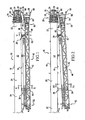
- Figure 1 is a top plan view of a telescoping boom have having front and rear supports for holding a boom extension and a boom extension mounted on the front and rear supports in a stored position;
- Figure 2 is a top plan view of the telescoping boom and boom extension of Figure 1 with a rear end of the boom extension shifted away from the boom;
- Figure 3 is a top plan view of the boom extension and boom of Figure 2 with the telescopic boom partially extended and the boom extension shifted longitudinally from the position illustrated in Figure 2 ;
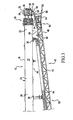
- Figure 4 is a side elevational view of the boom extension and boom of Figure 1 ;
- Figure 5 is an elevational view of the front boom extension support taken in the direction of arrows V-V of Figure 1 ;
- Figure 6 is an elevational view of the front boom extension support taken in the direction of arrows VI-VI in Figure 5 ;
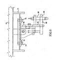
- Figure 7 is a plan view of a first portion of the front boom extension support taken in the direction of arrows VII-VII in Figure 6 ;
- Figure 8 is a plan view of a second portion of the front boom extension support taken in the direction of arrows VIII-VIII in Figure 6 ;
- Figure 9 is a perspective view of the second portion of the front boom extension support
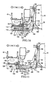
- Figure 10 is an elevational view, partly in section, of the rear boom extension support when the extension is positioned as in Figure 1 , taken in the direction of arrows X-X in Figure 1 ;
- Figure 11 is an elevational view, partly in section, of the rear boom extension support when the extension is positioned as in Figure 2 , taken in the direction of arrows XI-XI in Figure 2 ;
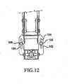
- Figure 12 is an elevational view taken in the direction of line XII-XII in Figure 11 ;
- Figure 13 is a first perspective view of the rear boom extension support when the extension is positioned as in Figure 1 ;
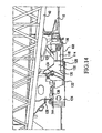
- Figure 14 is a perspective view af the rear boom extension support when the extension is positioned as in Figure 2 ;
- Figure 15 is a perspective view of the rear boom extension support when the extension is positioned as in Figure 3 ;
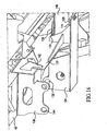
- Figure 16 is a second perspective view of the rear boom extension support of Figure 1 ;
- Figure 17 is a top plan view illustrating the boom extension swinging into a deployed position.
- FIGS 1-4 and 17 illustrate a boom 10 having a top 12, a bottom 14 a first side 16, a second side 18, a rear end 20 and a front end 22.
- Boom 10 further comprises a base section 24 and a plurality of telescoping sections 26 projecting from front end 22.
- the telescoping end of the boom may be referred to hereinafter as the front of the boom and the opposite end of the boom may be referred to as the rear or base of the boom.
- the front-most telescoping section 28 has a terminal end 30 having a first pair of upper and lower connector elements 32 on the first side 16 of boom 10 and a second pair of upper and lower connector elements 34 on second side 18 of boom 10.
- First side 16 of boom 10 further includes a front boom extension support 36 and a rear boom extension support 38 for supporting a boom extension along the boom 10 in a storage position when the boom extension is not needed.
- Boom extension 40 is also illustrated in Figures 1-4 and includes a top 42, a bottom 44, a first side 46, a second side 48, a front end 50 and a rear end 52.
- Front end 50 may be considered the base of the extension, to be mounted on the telescopic boom, as described below.
- Front end or base 50 includes diverging leg portions 54 each terminating in an attachment element.
- Leg portions 54 on first side 46 of extension 40 end in a first pair of attachment elements 56, and leg portions 54 on second side 48 of extension 40 end in a second pair of attachment elements 58.
- Each of the first and second pairs of attachment elements 56, 58 includes a hole or opening 60.
- a front connector assembly 62 is mounted on first side 46 of boom extension 40 and is adapted to engage the front boom extension support 36 on boom 10, and a rear connector assembly 64 is provided on first side 46 of boom extension 40 and is adapted to engage the rear boom extension support 38 an boom 10.
- Rear end 52 comprises the top of the extension when it is mounted on the telescopic boom.
- Front boom extension support 36 and front extension connector assembly 62 are illustrated in greater detail in Figures 5-9 .
- Front boom extension 36 comprises a main plate 70 having a plurality of slots 72 connected to first side 16 of boom 10 by support 71 welded to first side 16 of boom 10.
- Bolts 74 or similar fasteners extend through slots 72 in main plate 70 to connect main plate 70 to support 71. This arrangement allows the position of main plate 70 to be adjusted relative to support 71 and boom 10 as necessary to ensure proper operation of the boom extension as described hereinafter.
- a pair of upper spacing plates 76 extend perpendicularly from an upper portion of main plate 70, a lower spacing plate 78 extends perpendicularly from a lower portion of main plate 70, a pair of upper adjustable plates 80 is connected to upper spacing plates 76, and a lower adjustable plate 82 is connected to lower spacing plate 78 in each case using bolts or similar fasteners 84.
- Fasteners 84 extend through aligned openings in the spacing plates 76, 78 and adjustable plates 82, 84 and allow positions of the adjustable plates 80, 82 relative to first side 16 of boom 10 to be adjusted as necessary to ensure proper operation of the boom extension as described hereinafter.
- An alignment pin 86 is mounted on upper adjustable plates 80, extends in the direction of front end 22 of boom 10, and a has a generally circular cross section.
- An alignment tab 88 having an opening 89 projects from lower adjustable plate 82 also in the direction of front end 22 of boom 10.
- Front boom extension connector assembly 62 comprises an upper bracket 90 projecting normally from first side 46 of boom extension 40 which upper bracket 90 includes an alignment opening 92 configured to slidably receive alignment pin 86 on upper adjustable plate 80.
- Alignment opening 92 is sufficiently larger in diameter than the diameter of alignment pin 86 to allow the boom extension 40 to pivot on pin 90 relative to boom 10 by at least several degrees for reasons described herein.
- Front boom extension connector assembly 62 also includes a lower bracket 94 projecting normally from first side 46 of boom extension 40 and includes an alignment slot 96 somewhat larger than alignment tab 88 of lower adjustable plate 82 configured to receive alignment tab 88.
- a locking pin 98 passes through opening 89 in alignment tab 88 to limit longitudinal movement of boom extension 40 relative to boom 10 while allowing the boom extension 40 to pivot by at least several degrees.
- rear boom extension support 38 comprises upper and lower supports 100 welded to first side 16 of boom 10 and a support arm 102 having slots 104 connected to upper and lower supports 100 by bolts 106.
- the bolt and slot arrangement allows the position of support arm 102 and to be adjusted as necessary.
- a rail 108 extends from support arm 102 and includes an upper surface 110 generally parallel to a lower surface 112, the upper and lower surfaces being provided with wear pads 114 formed of a dense, low-friction plastic,
- An electromechanical actuator 116 having a housing 118, a motor 120 and a screw 122 is mounted to support arm 102, and motor 120 is configured to drive screw 122.
- a slider 124 having parallel upper and lower surfaces 126 each including a wear pad 128 slidingly engages rail 108 with the wear pads 128 of the slider in contact with the wear pads 114 of the rail 108.
- Screw 122 of electromechanical actuator 116 connects to slider 124 to move the slider 124 from a first, retracted, position, illustrated in Figure 10 to a second, extended position, illustrated in Figure 11 , relative to rail 108 and boom 10,
- Other types of actuators, including hydraulic actuators, could be used without departing from the scope of this invention.
- An alignment wall 1.30 projects from slider 124 in the direction of front end 50 of boom extension 40, and first and second support walls 1.32 project from slider 124 parallel to alignment wall 130.
- First and second rollers 134 are rotatably mounted between first and second support walls 132, and the roller closest to front end 50 of boom extension 40 is mounted at a lower elevation than the other roller 134.
- First and second alignment pins 136 project from slider 124 in the direction of the front 50 of the boom extension 40.
- Boom extension rear connector assembly 64 comprises a frame 138 depending from bottom 33 of boom extension 40 which frame includes a ramp wall 140, an alignment finger 142 illustrated in Figure 16 , and first and second alignment openings 144 configured to receive alignment pins 136 on slider 124.
- boom extension 40 is mounted in a storage and transport position against first side 16 of boom 10, as illustrated in Figures 1 and 4 .
- Boom 10 can be used in a traditional manner with boom extension 40 safely stored on the side thereof.
- alignment pin 86 of front boom extension support 36 projects through alignment opening 92 on the upper bracket 90 of front boom connector assembly 62
- alignment tab 88 of boom extension support 36 projects through alignment slot 96 on lower bracket 94 of boom connector assembly 62 while locking pin 98 passes through opening 89 in alignment tab 88.
- This arrangement substantially prevents boom extension 40 from separating from boom 10.
- alignment pins 136 on slider 124 project through alignment openings 144 on boom extension rear connector assembly 64 to secure the boom extension 40 to the slider 124, and linear actuator 116 is powered down to retain slider 124 in a retracted position on rail 108 relative to boom 10.
- first pair of attachment elements 56 on first side 46 of boom extension 40 are spaced from the first pair of connector elements 32 on the first side 16 of boom 10.
- linear actuator 116 is actuated by controller 146, illustrated in Figure 17 .
- the controller is preferably mounted near the front end 22 of boom 10 and may be connected to linear actuator motor 120 by a wire 148 or using an RF transmitter if the linear actuator 116 is suitably equipped with an RF receiver.
- Linear actuator motor 118 drives screw 122 to move slider 124 and therefore boom extension 40 away from boom 10 toward the position illustrated in Figure 2 .
- Controller 146 is preferably positioned close enough to connector elements 32 to enable an operator to observe the movement of the first pair of attachment elements 56 relative to the first connector elements 32 and turn off the linear actuator when all holes are aligned.
- a stop 150 may limit the outward movement of slider 124 relative to rail 108 and be positioned such that the openings 35 in the first pair of connector elements 32 are aligned with the openings 60 in the first pair of attachment elements 56 when the motion of the slider 124 is arrested by the stop.
- a stop 150 is still preferably provided to prevent slider 124 from disengaging from rail 108.
- boom extension 40 is connected to boom 10 at three points: at first pair of connector elements 32, at front connector assembly 62 and at rear connector assembly 64.
- an operator removes locking pin 98 from alignment tab 88 and actuates a boom controller (not shown) to extend front-most telescoping section 28 of the boom from the boom base section 24 a small distance such as a foot or two to move the boom extension 40 into the position illustrated in Figure 3 .
- boom extension 40 is slid longitudinally off alignment pin 86 and alignment tab 88 of front boom extension support 32 and off alignment pins 136 af rear boom extension support 34.
- boom extension 40 is caused to swing through an arc as illustrated in Figure 17 until the holes 60 in the second pair of attachment elements 56 align with the holes 35 in the second pair of connection elements 34, at which time additional pins (not shown) are inserted through the aligned openings to secure the boom extension 40 to the boom 10.
- the boom 10 together with boom extension 40 are operated in a conventional manner.
Landscapes
- Engineering & Computer Science (AREA)
- Mechanical Engineering (AREA)
- Jib Cranes (AREA)
Description
- The present invention is directed toward an automatically deployable boom extension and to a method of deploying same, and, more specifically, toward a boom having an actuator connected thereto for moving a portion of a boom extension away from the boom during a boom extension deployment and toward a method of controlling the actuator during the course of a boom extension deployment.
- To extend the reach of crane booms having telescopic boom sections, a side stowable jib or boom extension may be provided for connection to the nose assembly of the fly section or next adjacent boom section, as disclosed in
U.S. Pat. Nos. 3,785,505, dated January 15, 1974 , and4,483,447, dated November 20, 1984 . The entire contents of these patents are hereby incorporated by reference. - When moving the boom extension from a storage position on the side of the telescopic boom to a use position wherein the boom extension extends outwardly in alignment with the longitudinal axis of the boom, the boom extension is pivotally connected to one side of the nose assembly of the boom section and then swung around and connected to the other side of the nose assembly. The connections are made by a plurality of pins extending through aligned holes provided in the cooperating end portions of the boom extension and nose assembly of the fly section.
- On relatively small cranes, holes on the boom extension can be aligned with holes on the boom by manually pulling one end of the boom extension away from the boom and pivoting the boom extension on an intermediate support until the openings on the extension come into alignment with the openings on the boom nose. Cranes such as the one disclosed in
U.S. 3,785,505 , for example, include a roller on the boom extension that is rolled up a short ramp to carry the boom extension onto a boom extension support on the boom. While this arrangement performs satisfactorily, if an operator inadvertently removes the safety retaining pin from the intermediate support, pulling the rear portion of the boom extension away from the boom could result in the entire boom extension detaching from the boom and severely injuring the operator. Additional safety devices therefore must generally be provided to minimize this problem. - Another approach to boom extension deployment has been developed for relatively small cranes. In such cranes, the rear portion of the boom extension slides toward and away from the boom on a slider mounted on a rail. The boom extension is retained on the slider by pins projecting in the direction of the front end of the boom. Therefore, even when the slider is in the extended position, the boom extension will not detach from the slider until it is moved in the direction toward the outward end of the boom, and the extension will not detach from the boom even if an operator accidentally removes the safety pin from the intermediate support before moving the rear portion of the boom. Even with relatively small cranes, however, it is difficult for an operator to move the heavy boom extension as required to ensure that the front end of the boom extension is aligned with openings on the boom. This arrangement has therefore not been widely adopted on small cranes and is impracticable for larger cranes having heavier boom extensions.
-
JP 2001-270684 A - It would therefore be desirable to provide a boom extension that is easily shiftable from a storage position to a position wherein the boom extension can be connected to a boom regardless of the size of the boom extension and to provide a boom extension that will not readily detach from a boom.
- It is a general object of the present invention to provide an improved and useful crane in which the above-mentioned problems are eliminated.
- In order to achieve the above-mentioned object, there is provided a crane according to claim 1. In addition, there is provided a method according to
claim 14. Advantageous embodiments are defined by the dependent claims. - Advantageously, a crane that includes a telescoping boom having an outer boom member having a first end and an inner member slidably mounted in the outer boom member with a first end projecting from the outer boom member first end. The first end of the inner member includes a first connector element having an opening and a second connector element having an opening. The crane also includes a boom extension having a first end and a second end, the first end including first and second attachment elements each having an opening. The boom extension first side includes first and second spaced bracket assemblies, The boom extension is shiftable between a use position where the opening of the first attachment element is aligned with the opening of the first connector element and the opening of the second attachment element is aligned with the opening of the second connector element and a storage position where the boom extension overlies and is connected to first and second supports on the outer boom member and the second attachment element is spaced from the second connector element. The first support may be a holder for pivotably retaining the first bracket assembly and the second support may be a rail projecting from the outer boom member first side and a slider slidably supported by the rail. An actuator is connected between the slider and the boom for shifting the slider between a retracted position and an extended position relative to the outer boom member,
- Advantageously, method of deploying a boom extension on a telescoping crane boom that includes steps of providing a boom having an outer member having first and second supports and a telescoping inner member comprising a first end having first and second connector elements each having an opening where the second support may be a slider slidably mounted on a rail to be shiftable between a retracted and an extended position by an actuator. An aspect of the invention includes providing a boom extension having a first end including first and second attachment elements each having an opening, the boom extension having first and second bracket assemblies. The first bracket assembly is connected to the boom first support and the second bracket assembly is connected to the boom second support so that the first attachment element is spaced from the first connector element. The actuator is controlled to move the slider toward the extended position until the opening of a first attachment element is aligned with the opening of a first connector element. The first attachment element is connected to the first connector element. The boom extension is disconnected from the first and second supports by extending the inner member from the outer member, and the boom extension is pivoted about the boom extension first connector element until the opening of the second attachment element is aligned with the opening of the second connector element. Then the second attachment element is connected to the second connector element.
- These aspects and features of the invention and other will be better understood after a reading of the following detailed description together with the attached drawings wherein:
-
Figure 1 is a top plan view of a telescoping boom have having front and rear supports for holding a boom extension and a boom extension mounted on the front and rear supports in a stored position; -
Figure 2 is a top plan view of the telescoping boom and boom extension ofFigure 1 with a rear end of the boom extension shifted away from the boom; -
Figure 3 is a top plan view of the boom extension and boom ofFigure 2 with the telescopic boom partially extended and the boom extension shifted longitudinally from the position illustrated inFigure 2 ; -
Figure 4 is a side elevational view of the boom extension and boom ofFigure 1 ; -
Figure 5 is an elevational view of the front boom extension support taken in the direction of arrows V-V ofFigure 1 ; -
Figure 6 is an elevational view of the front boom extension support taken in the direction of arrows VI-VI inFigure 5 ; -
Figure 7 is a plan view of a first portion of the front boom extension support taken in the direction of arrows VII-VII inFigure 6 ; -
Figure 8 is a plan view of a second portion of the front boom extension support taken in the direction of arrows VIII-VIII inFigure 6 ; -
Figure 9 is a perspective view of the second portion of the front boom extension support; -
Figure 10 is an elevational view, partly in section, of the rear boom extension support when the extension is positioned as inFigure 1 , taken in the direction of arrows X-X inFigure 1 ; -
Figure 11 is an elevational view, partly in section, of the rear boom extension support when the extension is positioned as inFigure 2 , taken in the direction of arrows XI-XI inFigure 2 ; -
Figure 12 is an elevational view taken in the direction of line XII-XII inFigure 11 ; -
Figure 13 is a first perspective view of the rear boom extension support when the extension is positioned as inFigure 1 ; -
Figure 14 is a perspective view af the rear boom extension support when the extension is positioned as inFigure 2 ; -
Figure 15 is a perspective view of the rear boom extension support when the extension is positioned as inFigure 3 ; -
Figure 16 is a second perspective view of the rear boom extension support ofFigure 1 ; and -
Figure 17 is a top plan view illustrating the boom extension swinging into a deployed position. - Referring now to the drawings, which are for purposes of illustrating preferred embodiments of the invention only and not for the purpose of limiting same,
Figures 1-4 and17 illustrate aboom 10 having atop 12, a bottom 14 afirst side 16, asecond side 18, arear end 20 and afront end 22.Boom 10 further comprises abase section 24 and a plurality oftelescoping sections 26 projecting fromfront end 22.
The telescoping end of the boom may be referred to hereinafter as the front of the boom and the opposite end of the boom may be referred to as the rear or base of the boom. These terms will also be used to describe the boom extension mounted on the side of the boom; that is the "front" of the boom extension is the portion closest to the telescoping portion of the boom when the extension is mounted on the boom even though the front and rear portions of the boom extension will change position as the boom extension swings into its use position (see, e.g.Figure 17 ), Relative directional terms such as "above" and "below" may also be used to refer to the boom in its normal operating position with thetop 12 ofboom 10 facing upwardly andbottom 14 facing the ground. - The
front-most telescoping section 28 has aterminal end 30 having a first pair of upper andlower connector elements 32 on thefirst side 16 ofboom 10 and a second pair of upper andlower connector elements 34 onsecond side 18 ofboom 10.First side 16 ofboom 10 further includes a frontboom extension support 36 and a rearboom extension support 38 for supporting a boom extension along theboom 10 in a storage position when the boom extension is not needed. -
Boom extension 40 is also illustrated inFigures 1-4 and includes a top 42, a bottom 44, afirst side 46, asecond side 48, afront end 50 and arear end 52.Front end 50 may be considered the base of the extension, to be mounted on the telescopic boom, as described below. Front end orbase 50 includes divergingleg portions 54 each terminating in an attachment element.Leg portions 54 onfirst side 46 ofextension 40 end in a first pair ofattachment elements 56, andleg portions 54 onsecond side 48 ofextension 40 end in a second pair ofattachment elements 58. Each of the first and second pairs ofattachment elements opening 60. Afront connector assembly 62 is mounted onfirst side 46 ofboom extension 40 and is adapted to engage the frontboom extension support 36 onboom 10, and arear connector assembly 64 is provided onfirst side 46 ofboom extension 40 and is adapted to engage the rearboom extension support 38 anboom 10.Rear end 52 comprises the top of the extension when it is mounted on the telescopic boom. - Front
boom extension support 36 and frontextension connector assembly 62 are illustrated in greater detail inFigures 5-9 .Front boom extension 36 comprises amain plate 70 having a plurality ofslots 72 connected tofirst side 16 ofboom 10 bysupport 71 welded tofirst side 16 ofboom 10.Bolts 74 or similar fasteners extend throughslots 72 inmain plate 70 to connectmain plate 70 to support 71. This arrangement allows the position ofmain plate 70 to be adjusted relative to support 71 andboom 10 as necessary to ensure proper operation of the boom extension as described hereinafter. - A pair of
upper spacing plates 76 extend perpendicularly from an upper portion ofmain plate 70, alower spacing plate 78 extends perpendicularly from a lower portion ofmain plate 70, a pair of upperadjustable plates 80 is connected toupper spacing plates 76, and a loweradjustable plate 82 is connected to lower spacingplate 78 in each case using bolts orsimilar fasteners 84.Fasteners 84 extend through aligned openings in thespacing plates adjustable plates adjustable plates first side 16 ofboom 10 to be adjusted as necessary to ensure proper operation of the boom extension as described hereinafter. Analignment pin 86 is mounted on upperadjustable plates 80, extends in the direction offront end 22 ofboom 10, and a has a generally circular cross section. Analignment tab 88 having an opening 89 projects from loweradjustable plate 82 also in the direction offront end 22 ofboom 10. - Front boom
extension connector assembly 62 comprises anupper bracket 90 projecting normally fromfirst side 46 ofboom extension 40 whichupper bracket 90 includes analignment opening 92 configured to slidably receivealignment pin 86 on upperadjustable plate 80.Alignment opening 92 is sufficiently larger in diameter than the diameter ofalignment pin 86 to allow theboom extension 40 to pivot onpin 90 relative to boom 10 by at least several degrees for reasons described herein. - Front boom
extension connector assembly 62 also includes alower bracket 94 projecting normally fromfirst side 46 ofboom extension 40 and includes analignment slot 96 somewhat larger thanalignment tab 88 of loweradjustable plate 82 configured to receivealignment tab 88. A lockingpin 98 passes through opening 89 inalignment tab 88 to limit longitudinal movement ofboom extension 40 relative to boom 10 while allowing theboom extension 40 to pivot by at least several degrees. - Rear
boom extension support 38 and rear boomextension connector assembly 64 are illustrated in greater detail inFigures 10-15 . With reference toFigure 10 , rearboom extension support 38 comprises upper andlower supports 100 welded tofirst side 16 ofboom 10 and asupport arm 102 havingslots 104 connected to upper andlower supports 100 bybolts 106. The bolt and slot arrangement allows the position ofsupport arm 102 and to be adjusted as necessary. Arail 108 extends fromsupport arm 102 and includes anupper surface 110 generally parallel to alower surface 112, the upper and lower surfaces being provided withwear pads 114 formed of a dense, low-friction plastic, - An
electromechanical actuator 116 having ahousing 118, amotor 120 and ascrew 122 is mounted to supportarm 102, andmotor 120 is configured to drivescrew 122. Aslider 124 having parallel upper andlower surfaces 126 each including awear pad 128 slidingly engagesrail 108 with thewear pads 128 of the slider in contact with thewear pads 114 of therail 108. Screw 122 ofelectromechanical actuator 116 connects toslider 124 to move theslider 124 from a first, retracted, position, illustrated inFigure 10 to a second, extended position, illustrated inFigure 11 , relative to rail 108 andboom 10, Other types of actuators, including hydraulic actuators, could be used without departing from the scope of this invention. - An alignment wall 1.30 projects from
slider 124 in the direction offront end 50 ofboom extension 40, and first and second support walls 1.32 project fromslider 124 parallel toalignment wall 130. First andsecond rollers 134 are rotatably mounted between first andsecond support walls 132, and the roller closest tofront end 50 ofboom extension 40 is mounted at a lower elevation than theother roller 134. First and second alignment pins 136 project fromslider 124 in the direction of thefront 50 of theboom extension 40. - Boom extension
rear connector assembly 64 comprises aframe 138 depending from bottom 33 ofboom extension 40 which frame includes aramp wall 140, analignment finger 142 illustrated inFigure 16 , and first andsecond alignment openings 144 configured to receivealignment pins 136 onslider 124. - The deployment of
boom extension 40 is discussed below.Boom extension 40 is mounted in a storage and transport position againstfirst side 16 ofboom 10, as illustrated inFigures 1 and4 .Boom 10 can be used in a traditional manner withboom extension 40 safely stored on the side thereof. As illustrated inFigure 5 , in this configuration,alignment pin 86 of frontboom extension support 36 projects throughalignment opening 92 on theupper bracket 90 of frontboom connector assembly 62, andalignment tab 88 ofboom extension support 36 projects throughalignment slot 96 onlower bracket 94 ofboom connector assembly 62 while lockingpin 98 passes through opening 89 inalignment tab 88. This arrangement substantially preventsboom extension 40 from separating fromboom 10. - Likewise, with reference to
Figure 13 , alignment pins 136 onslider 124 project throughalignment openings 144 on boom extensionrear connector assembly 64 to secure theboom extension 40 to theslider 124, andlinear actuator 116 is powered down to retainslider 124 in a retracted position onrail 108 relative to boom 10. In this configuration, as will be appreciated fromFigure 1 , the first pair ofattachment elements 56 onfirst side 46 ofboom extension 40 are spaced from the first pair ofconnector elements 32 on thefirst side 16 ofboom 10. - To deploy
boom extension 40 to a use position mounted on and aligned withboom 10 as illustrated inFigure 17 ,linear actuator 116 is actuated bycontroller 146, illustrated inFigure 17 . The controller is preferably mounted near thefront end 22 ofboom 10 and may be connected tolinear actuator motor 120 by awire 148 or using an RF transmitter if thelinear actuator 116 is suitably equipped with an RF receiver.Linear actuator motor 118 drives screw 122 to moveslider 124 and therefore boomextension 40 away fromboom 10 toward the position illustrated inFigure 2 . -
Slider 124 is driven away fromboom 10 until theholes 60 in the first pair ofattachment elements 56 onboom extension 40 are aligned with theholes 35 on the first pair ofconnector elements 32 ofboom 10 as illustrated inFigure 2 .Controller 146 is preferably positioned close enough toconnector elements 32 to enable an operator to observe the movement of the first pair ofattachment elements 56 relative to thefirst connector elements 32 and turn off the linear actuator when all holes are aligned. According to the invention, astop 150 may limit the outward movement ofslider 124 relative to rail 108 and be positioned such that theopenings 35 in the first pair ofconnector elements 32 are aligned with theopenings 60 in the first pair ofattachment elements 56 when the motion of theslider 124 is arrested by the stop. Even when the stop is not used to align theholes 35 in theconnection elements 32 with theholes 60 in theattachment elements 56, astop 150 is still preferably provided to preventslider 124 from disengaging fromrail 108. When the holes in theconnector elements 32 are aligned with theopenings 60 in theattachment elements 56, an operator inserts pins (not illustrated) through the first pair of aligned openings to secure a first portion of theboom extension 40 to boom 10. - In this configuration,
boom extension 40 is connected to boom 10 at three points: at first pair ofconnector elements 32, atfront connector assembly 62 and atrear connector assembly 64. At this time, an operator removes lockingpin 98 fromalignment tab 88 and actuates a boom controller (not shown) to extendfront-most telescoping section 28 of the boom from the boom base section 24 a small distance such as a foot or two to move theboom extension 40 into the position illustrated inFigure 3 . In this configuration,boom extension 40 is slid longitudinally offalignment pin 86 andalignment tab 88 of frontboom extension support 32 and off alignment pins 136 af rearboom extension support 34. Once free of the boom extension supports, and with the help of an operator who pushes theboom extension 40 or raises or lowers thefront end 22 ofboom 10 in a well known manner,boom extension 40 is caused to swing through an arc as illustrated inFigure 17 until theholes 60 in the second pair ofattachment elements 56 align with theholes 35 in the second pair ofconnection elements 34, at which time additional pins (not shown) are inserted through the aligned openings to secure theboom extension 40 to theboom 10. After this assembly, theboom 10 together withboom extension 40 are operated in a conventional manner. - To
stow boom extension 40, the above steps are substantially reversed. Pins (not illustrated) are removed fromsecond connector elements 34 freeing thesecond side 48 ofboom extension 40 from the boom, and the operator pushes the boom extension (or manipulates the position of the boom) toswing boom extension 40 through an arc until it is more or less aligned with theboom 10 in the configuration illustrated inFigure 3 . Whilemaneuvering boom extension 40 into this position,front-most telescoping portion 28 ofboom 10 is not fully retracted. When theboom extension 40 is adjacent the side ofboom 10, in the configuration ofFigure 3 ,front-most telescoping portion 28 is retracted intoboom housing 24 causingramp wall 140 on rear connector assembly 64 (Figure 15 ) to engagerollers 134 and guidealignment openings 144 toward alignment pins 136 of rearboom extension support 34. At the same time,alignment finger 142 overlaps alignment wall 130 (Figure 16 ) to further guide and secure theboom extension 40 to theboom 10. Also thealignment pin 86 andalignment tab 88 of frontboom extension support 36 engage thealignment opening 92 inbracket 90 and thealignment slot 96 inlower bracket 94, At this time an operator installs lockingpin 98 intoalignment tab 88.Linear actuator 116 is then operated to slideslider 124 onrail 108 towardboom 10 to pullboom extension 40 back into the storage position ofFigure 1 . - With the above described system, even a large boom extension can readily be deployed by a sole operator while reducing the possibility of accidentally disconnecting a boom extension from the boom and injuring an operator or other property. The sole operator can also observe the position of the boom extension relative to the boom to align the openings without repeatedly walking back to the rear end of the boom and making further adjustments. Thus, when normal wear on the boom causes changes in the relative positions of elements of the boom and boom extension, the operator can correct for such wear by visual observation adn use of the remote controller. The linear actuator further serves as a safety interlock and will substantially prevent the rear portion of the boom extension from being pulled away from the boom unless the actuator is used.
- The present invention has been described herein in terms of an illustrated preferred embodiment. Various modifications and additions to this embodiment will become apparent to those skilled in the relevant arts upon a reading of the foregoing disclosure. It is intended that all such modifications and additions comprise a part of the present invention to the extent they come within the scope of the several claims appended hereto.
Claims (16)
- A crane comprising:a telescoping boom (10) comprising a base boom member (24) and an inner telescopic member (28) slidably mounted in said base boom member (24) and having a first end (30) projecting from said base boom member (24), said first end (30) of said inner member (28) including a first connector element (32) at a first side (16) thereof and a second connector element (34) at a second side (18) thereof;a boom extension (40) having a first end (50) and a second end (52), said boom extension first end (50) including a first attachment element (56) at a first side (46) thereof and a second attachment element (58) at a second side (48) thereof, said boom extension (40) further including first and second spaced bracket assemblies (62, 64), said first bracket assembly (62) being located between said second bracket assembly (64) and said boom extension first end (50);said boom extension (40) being shiftable between a use position wherein said first attachment element (56) is connected to said first connector element (32) and said second attachment element (58) is connected to said second connector element (34) and a storage position wherein said boom extension (40) is connected to first and second supports on said base boom member (24);said first support (36) comprising a holder for pivotably retaining said first bracket assembly (62);said second support (38) comprising a rail (108) projecting from said base boom member (24) and a slider (124) slidably supported by said rail (108); andan actuator (116) connected between said slider (124) and said boom (10) for shifting said slider (124) between a retracted position and an extended position relative to said base boom member (24), characterized by a stop (150) limiting the outward movement of the slider (124) relative to the rail (108) and which is positioned such that first openings (35) in said first connector element (32) are aligned with second openings (60) in the first attachment element (56) when the motion of the slider (124) is arrested by the stop (150).
- The crane of claim 1 wherein said rail (108) comprises a planar upper surface (110) and said slider (124) comprises a planar lower surface (126) slidably engaging said rail upper surface (110).
- The crane of claim 1 wherein said rail (108) includes a first wear plate (114) mounted on a first rail surface (110) and said slider (124) includes a second wear plate (128) mounted on a first slider surface (126) facing said rail first surface (110), said first wear plate (114) contacting said second wear plate when said slider (124) is between said retracted position and said extended position.
- The crane of claim 3 wherein said first wear plate (114) substantially overlies said second wear plate (128) when said slider (124) is in said retracted position.
- The crane of claim 1 wherein said actuator (116) comprises an electromechanical actuator.
- The crane of claim 1 wherein said actuator (116) comprises a linear actuator.
- The crane of claim 1 wherein said actuator (116) comprises an electromechanical screw drive (122).
- The crane of claim 1 including a controller (146) in communication with said actuator (116) for remotely controlling said actuator (116).
- The crane of claim 1 wherein said first connector element (32) is aligned with said first attachment element (56) when said slider (124) is in a position between the retracted position and the extended position.
- The crane of claim 1 wherein said first connector element (32) is aligned with said first attachment element (56) when said slider (124) is in said extended position.
- The crane of claim 8 wherein said controller (146) is positioned adjacent to the boom extension first end (50) with said boom extension (40) in the storage position.
- The crane of claim 8 wherein said controller (146) comprises an radiofrequency transmitter for sending control signals to said actuator (116).
- The crane of claim 8 wherein said controller (146) is connected to said actuator (116) by a wire (148), said wire (148) extending from said actuator (116) a distance sufficient to position said controller (146) adjacent said first connector element (32).
- A method of deploying a boom extension (40) on a telescoping crane boom (10) comprising the steps of:providing a boom (10) having a base boom member (24) comprising first and second supports (36, 38), and a telescoping inner member (28) comprising a first end (30) having first and second connector elements (32, 34), the second support (38) comprising a slider (124) slidably mounted on a rail (108) and shiftable between a retracted and an extended position by an actuator (116);providing a boom extension (40) having a first end (50) including a first attachment element (56) and a second attachment element (58) and a second end (52), and first and second bracket assemblies (62, 64) between the first and second boom extension ends (50, 52);connecting the first bracket assembly (62) to the boom first support (36);connecting the second bracket assembly (64) to the boom second support (38) so that the first attachment element (56) is spaced from the first connector element (32);controlling the actuator (116) to move the slider (124) toward the extended position until the first attachment element (56) is aligned with the first connector element (32);connecting the first attachment element (56) to the first connector element (32);disconnecting the boom extension (40) from the first and second supports (36, 38) by extending the inner member (28) from the base member (24);pivoting the boom extension (40) about the boom extension first connector element (32) until the second attachment element (58) is aligned with the second connector element (34); andconnecting the second attachment element (58) to the second connector element (34), characterized by providing a stop (150) limiting the outward movement of the slider (124) relative to the rail (108) and by positioning said stop (150) such that first openings (35) in said first connector element (32) are aligned with said second openings (60) in the first attachment element (56) when the motion of the slider (124) is arrested by the stop (150).
- The method of claim 14 wherein said step of connecting the first attachment element (56) to the first connector element (32) comprises the step of inserting a pin through aligned openings (60) of the first attachment element (56) and the first connector element (32).
- The method of claim 14 wherein said step of controlling the actuator (116) to move the slider (124) toward the extended position comprises the step of powering the actuator (116) to move the slider (124) to the extended position.
Applications Claiming Priority (1)
| Application Number | Priority Date | Filing Date | Title |
|---|---|---|---|
| US11/703,683 US7337912B1 (en) | 2007-02-08 | 2007-02-08 | Automatically deployable boom extension and method of deploying same |
Publications (2)
| Publication Number | Publication Date |
|---|---|
| EP1955974A1 EP1955974A1 (en) | 2008-08-13 |
| EP1955974B1 true EP1955974B1 (en) | 2011-03-30 |
Family
ID=39125335
Family Applications (1)
| Application Number | Title | Priority Date | Filing Date |
|---|---|---|---|
| EP08150930A Active EP1955974B1 (en) | 2007-02-08 | 2008-02-01 | Automatically deployable boom extension and method of deploying same |
Country Status (7)
| Country | Link |
|---|---|
| US (1) | US7337912B1 (en) |
| EP (1) | EP1955974B1 (en) |
| JP (1) | JP5150808B2 (en) |
| CN (1) | CN101274730B (en) |
| BR (1) | BRPI0800082A (en) |
| DE (1) | DE602008005798D1 (en) |
| ES (1) | ES2359216T3 (en) |
Families Citing this family (15)
| Publication number | Priority date | Publication date | Assignee | Title |
|---|---|---|---|---|
| US7878346B1 (en) * | 2008-08-25 | 2011-02-01 | Link-Belt Construction Equipment Co., L.P., Lllp | Adaptable boom extension for a mobile crane having a telescoping boom |
| US7926670B2 (en) * | 2009-05-01 | 2011-04-19 | Westchester Capital, Llc | Truck mounted telescopic boom structure including a stowable jib boom with a stowable personnel basket |
| DE102009022262A1 (en) * | 2009-05-22 | 2010-11-25 | Terex Demag Gmbh | Angular adjustment of a boom system |
| CN101579810B (en) * | 2009-06-19 | 2011-06-01 | 长沙中联重工科技发展股份有限公司 | Boom assembly and debugging equipment and boom assembly and debugging method |
| US8739988B2 (en) * | 2010-09-20 | 2014-06-03 | Manitowoc Crane Companies, Llc | Pinned connection system for crane column segments |
| US8801354B2 (en) | 2011-03-30 | 2014-08-12 | Terex South Dakota, Inc. | Wearpad arrangement |
| US8833519B1 (en) | 2012-03-01 | 2014-09-16 | Westchester Capital, Llc | Vehicle mounted telescopic boom structure |
| DE102012023357B4 (en) | 2012-11-22 | 2014-11-20 | Terex Cranes Germany Gmbh | Device and method for positioning and locking of supplementary parts for crane operation |
| CN104176657A (en) * | 2014-09-05 | 2014-12-03 | 徐州重型机械有限公司 | Crane and arm bracket thereof |
| JP6520270B2 (en) * | 2015-03-20 | 2019-05-29 | 株式会社タダノ | Jib connection structure |
| KR101848736B1 (en) * | 2016-08-22 | 2018-05-21 | 주식회사 수산중공업 | Crane Boom and Connection Method between Main boom and Auxiliary boom |
| US10589966B2 (en) | 2017-03-02 | 2020-03-17 | Manitowoc Crane Companies, Llc | Jib coupling system for jib stowage |
| JP7270799B2 (en) * | 2017-12-27 | 2023-05-10 | 極東開発工業株式会社 | Boom device |
| DE102019202575B3 (en) | 2019-02-26 | 2020-07-02 | Tadano Faun Gmbh | Mast attachment tip for a mobile crane and mobile crane |
| DE102020118261B4 (en) * | 2020-07-10 | 2024-05-16 | Liebherr-Werk Ehingen Gmbh | Mobile crane with folding jib safety device and folding jib for such a crane |
Family Cites Families (19)
| Publication number | Priority date | Publication date | Assignee | Title |
|---|---|---|---|---|
| US3785505A (en) | 1970-12-15 | 1974-01-15 | Kidde & Co Walter | Side stowable jib for crane booms and jib mounting |
| US3945333A (en) | 1974-12-20 | 1976-03-23 | Harnischfeger Corporation | Means for storing and connecting jib for telescopic boom of mobile crane |
| US3968884A (en) | 1974-12-20 | 1976-07-13 | Harnischfeger Corporation | Storage means for jib for telescopic boom of mobile crane |
| US4045923A (en) | 1976-05-06 | 1977-09-06 | Walter Kidde & Company, Inc. | Telescopic swingaway jib |
| US4091936A (en) | 1976-11-15 | 1978-05-30 | The Warner & Swasey Company | Apparatus for extending a boom assembly |
| US4141455A (en) | 1977-07-14 | 1979-02-27 | Harnischfeger Corporation | Means for storing and connecting jib on telescopic crane boom |
| US4318488A (en) | 1980-07-28 | 1982-03-09 | Harnischfeger Corporation | Method of extending a jib of a telescopic crane |
| US4431109A (en) | 1981-02-25 | 1984-02-14 | Fmc Corporation | Boom extension stowage system |
| US4491229A (en) | 1981-02-25 | 1985-01-01 | Fmc Corporation | Boom extension stowage system |
| US4483447A (en) | 1982-05-26 | 1984-11-20 | Kidde, Inc. | Safety mounting for side stowable boom extension or jib |
| US4621742A (en) | 1985-01-25 | 1986-11-11 | Harnischfeger Corporation | Boom extension storage means and mechanisms |
| US4953724A (en) * | 1989-06-29 | 1990-09-04 | Kabushiki Kaisha Kobe Seiko Sho | Jib stretching and folding device |
| JPH04125297A (en) * | 1990-09-13 | 1992-04-24 | Kobe Steel Ltd | Gib swinging and housing device for crane |
| US5111945A (en) | 1991-09-13 | 1992-05-12 | Kidde Industries, Inc. | Boom extension alignment device |
| US5673805A (en) | 1995-02-28 | 1997-10-07 | National Crane Corporation | Jib pin alignment jack assembly |
| JPH11199177A (en) * | 1998-01-09 | 1999-07-27 | Kobe Steel Ltd | Crane jib overhang and storage method and its device |
| JP4540788B2 (en) * | 2000-02-14 | 2010-09-08 | 株式会社タダノ | Jib storage device for mobile crane |
| JP4564622B2 (en) | 2000-03-27 | 2010-10-20 | 株式会社タダノ | Auxiliary jib storage device |
| JP4227748B2 (en) * | 2002-01-17 | 2009-02-18 | 株式会社タダノ | Crane car jib storage device |
-
2007
- 2007-02-08 US US11/703,683 patent/US7337912B1/en active Active
-
2008
- 2008-02-01 ES ES08150930T patent/ES2359216T3/en active Active
- 2008-02-01 DE DE602008005798T patent/DE602008005798D1/en active Active
- 2008-02-01 EP EP08150930A patent/EP1955974B1/en active Active
- 2008-02-04 CN CN2008100048486A patent/CN101274730B/en active Active
- 2008-02-06 JP JP2008026502A patent/JP5150808B2/en active Active
- 2008-02-07 BR BRPI0800082-4A patent/BRPI0800082A/en not_active IP Right Cessation
Also Published As
| Publication number | Publication date |
|---|---|
| CN101274730A (en) | 2008-10-01 |
| CN101274730B (en) | 2011-04-06 |
| DE602008005798D1 (en) | 2011-05-12 |
| EP1955974A1 (en) | 2008-08-13 |
| JP2008195538A (en) | 2008-08-28 |
| ES2359216T3 (en) | 2011-05-19 |
| HK1119647A1 (en) | 2009-03-13 |
| BRPI0800082A (en) | 2008-09-23 |
| US7337912B1 (en) | 2008-03-04 |
| JP5150808B2 (en) | 2013-02-27 |
Similar Documents
| Publication | Publication Date | Title |
|---|---|---|
| US7337912B1 (en) | Automatically deployable boom extension and method of deploying same | |
| JP6821213B2 (en) | A quick exchange coupling device and a quick exchange coupling system equipped with the quick exchange coupling device. | |
| JP5568453B2 (en) | Mobile crane and method of assembling mobile crane | |
| US20110147331A1 (en) | Jib stowing device for jib crane vehicle | |
| WO1997037927A1 (en) | Apparatus and method for extending and storing jib of crane | |
| CN108529454B (en) | Boom coupling system for boom storage | |
| JP3101026B2 (en) | Jib overhanging device for crane with auxiliary jib | |
| JP2015040109A (en) | Counterweight position adjustment mechanism | |
| JP3566418B2 (en) | Mobile crane with luffing jib | |
| HK1119647B (en) | Automatically deployable boom extension and method of deploying same | |
| JP5583065B2 (en) | Container handling vehicle | |
| EP0728695A1 (en) | Device for extending and storing horizontal boom | |
| JP2018131311A (en) | Counterweight device and construction device | |
| JP2011121671A (en) | Method of connecting tension rope and method of linking jib in jib-equipped boom working vehicle provided with device restraining horizontal deflection of boom | |
| JP2012111569A (en) | Crane | |
| JP2001328793A (en) | Crane equipment | |
| KR20180021410A (en) | Crane Boom and Connection Method between Main boom and Auxiliary boom | |
| JP3238976B2 (en) | Jib removal device for jib boom | |
| JP4809939B2 (en) | Jib attachment and detachment device for telescopic boom tip of mobile crane | |
| JP4420487B2 (en) | Mobile crane device with auxiliary jib | |
| JPH078548Y2 (en) | Jib storage device for vehicle-mounted crane | |
| JP5352164B2 (en) | Jib overhang storage device for crane equipment | |
| CN109689560B (en) | crane | |
| JP2022066822A (en) | Crane and assembling method and disassembling method of crane | |
| JP3433693B2 (en) | Crane backstop |
Legal Events
| Date | Code | Title | Description |
|---|---|---|---|
| PUAI | Public reference made under article 153(3) epc to a published international application that has entered the european phase |
Free format text: ORIGINAL CODE: 0009012 |
|
| AK | Designated contracting states |
Kind code of ref document: A1 Designated state(s): AT BE BG CH CY CZ DE DK EE ES FI FR GB GR HR HU IE IS IT LI LT LU LV MC MT NL NO PL PT RO SE SI SK TR |
|
| AX | Request for extension of the european patent |
Extension state: AL BA MK RS |
|
| 17P | Request for examination filed |
Effective date: 20080930 |
|
| 17Q | First examination report despatched |
Effective date: 20081104 |
|
| REG | Reference to a national code |
Ref country code: HK Ref legal event code: DE Ref document number: 1119647 Country of ref document: HK |
|
| AKX | Designation fees paid |
Designated state(s): DE ES FR GB |
|
| GRAP | Despatch of communication of intention to grant a patent |
Free format text: ORIGINAL CODE: EPIDOSNIGR1 |
|
| RAP1 | Party data changed (applicant data changed or rights of an application transferred) |
Owner name: MANITOWOC CRANE COMPANIES, LLC |
|
| GRAS | Grant fee paid |
Free format text: ORIGINAL CODE: EPIDOSNIGR3 |
|
| GRAA | (expected) grant |
Free format text: ORIGINAL CODE: 0009210 |
|
| AK | Designated contracting states |
Kind code of ref document: B1 Designated state(s): DE ES FR GB |
|
| REG | Reference to a national code |
Ref country code: GB Ref legal event code: FG4D |
|
| REF | Corresponds to: |
Ref document number: 602008005798 Country of ref document: DE Date of ref document: 20110512 Kind code of ref document: P |
|
| REG | Reference to a national code |
Ref country code: DE Ref legal event code: R096 Ref document number: 602008005798 Country of ref document: DE Effective date: 20110512 |
|
| REG | Reference to a national code |
Ref country code: ES Ref legal event code: FG2A Ref document number: 2359216 Country of ref document: ES Kind code of ref document: T3 Effective date: 20110519 |
|
| REG | Reference to a national code |
Ref country code: HK Ref legal event code: GR Ref document number: 1119647 Country of ref document: HK |
|
| PLBE | No opposition filed within time limit |
Free format text: ORIGINAL CODE: 0009261 |
|
| STAA | Information on the status of an ep patent application or granted ep patent |
Free format text: STATUS: NO OPPOSITION FILED WITHIN TIME LIMIT |
|
| 26N | No opposition filed |
Effective date: 20120102 |
|
| REG | Reference to a national code |
Ref country code: DE Ref legal event code: R097 Ref document number: 602008005798 Country of ref document: DE Effective date: 20120102 |
|
| PGFP | Annual fee paid to national office [announced via postgrant information from national office to epo] |
Ref country code: GB Payment date: 20130130 Year of fee payment: 6 Ref country code: ES Payment date: 20130214 Year of fee payment: 6 Ref country code: FR Payment date: 20130301 Year of fee payment: 6 |
|
| GBPC | Gb: european patent ceased through non-payment of renewal fee |
Effective date: 20140201 |
|
| REG | Reference to a national code |
Ref country code: FR Ref legal event code: ST Effective date: 20141031 |
|
| PG25 | Lapsed in a contracting state [announced via postgrant information from national office to epo] |
Ref country code: GB Free format text: LAPSE BECAUSE OF NON-PAYMENT OF DUE FEES Effective date: 20140201 Ref country code: FR Free format text: LAPSE BECAUSE OF NON-PAYMENT OF DUE FEES Effective date: 20140228 |
|
| REG | Reference to a national code |
Ref country code: ES Ref legal event code: FD2A Effective date: 20151002 |
|
| PG25 | Lapsed in a contracting state [announced via postgrant information from national office to epo] |
Ref country code: ES Free format text: LAPSE BECAUSE OF NON-PAYMENT OF DUE FEES Effective date: 20140202 |
|
| P01 | Opt-out of the competence of the unified patent court (upc) registered |
Effective date: 20230523 |
|
| PGFP | Annual fee paid to national office [announced via postgrant information from national office to epo] |
Ref country code: DE Payment date: 20260218 Year of fee payment: 19 |