EP1955911A2 - Device and method for controlling occupant security devices - Google Patents
Device and method for controlling occupant security devices Download PDFInfo
- Publication number
- EP1955911A2 EP1955911A2 EP08100293A EP08100293A EP1955911A2 EP 1955911 A2 EP1955911 A2 EP 1955911A2 EP 08100293 A EP08100293 A EP 08100293A EP 08100293 A EP08100293 A EP 08100293A EP 1955911 A2 EP1955911 A2 EP 1955911A2
- Authority
- EP
- European Patent Office
- Prior art keywords
- signal
- frequency
- ratio
- accident
- evaluation
- Prior art date
- Legal status (The legal status is an assumption and is not a legal conclusion. Google has not performed a legal analysis and makes no representation as to the accuracy of the status listed.)
- Granted
Links
Images


Classifications
-
- B—PERFORMING OPERATIONS; TRANSPORTING
- B60—VEHICLES IN GENERAL
- B60R—VEHICLES, VEHICLE FITTINGS, OR VEHICLE PARTS, NOT OTHERWISE PROVIDED FOR
- B60R21/00—Arrangements or fittings on vehicles for protecting or preventing injuries to occupants or pedestrians in case of accidents or other traffic risks
- B60R21/01—Electrical circuits for triggering passive safety arrangements, e.g. airbags, safety belt tighteners, in case of vehicle accidents or impending vehicle accidents
- B60R21/013—Electrical circuits for triggering passive safety arrangements, e.g. airbags, safety belt tighteners, in case of vehicle accidents or impending vehicle accidents including means for detecting collisions, impending collisions or roll-over
- B60R21/0132—Electrical circuits for triggering passive safety arrangements, e.g. airbags, safety belt tighteners, in case of vehicle accidents or impending vehicle accidents including means for detecting collisions, impending collisions or roll-over responsive to vehicle motion parameters, e.g. to vehicle longitudinal or transversal deceleration or speed value
- B60R21/01332—Electrical circuits for triggering passive safety arrangements, e.g. airbags, safety belt tighteners, in case of vehicle accidents or impending vehicle accidents including means for detecting collisions, impending collisions or roll-over responsive to vehicle motion parameters, e.g. to vehicle longitudinal or transversal deceleration or speed value by frequency or waveform analysis
-
- B—PERFORMING OPERATIONS; TRANSPORTING
- B60—VEHICLES IN GENERAL
- B60R—VEHICLES, VEHICLE FITTINGS, OR VEHICLE PARTS, NOT OTHERWISE PROVIDED FOR
- B60R21/00—Arrangements or fittings on vehicles for protecting or preventing injuries to occupants or pedestrians in case of accidents or other traffic risks
- B60R21/34—Protecting non-occupants of a vehicle, e.g. pedestrians
-
- B—PERFORMING OPERATIONS; TRANSPORTING
- B60—VEHICLES IN GENERAL
- B60R—VEHICLES, VEHICLE FITTINGS, OR VEHICLE PARTS, NOT OTHERWISE PROVIDED FOR
- B60R21/00—Arrangements or fittings on vehicles for protecting or preventing injuries to occupants or pedestrians in case of accidents or other traffic risks
- B60R2021/003—Arrangements or fittings on vehicles for protecting or preventing injuries to occupants or pedestrians in case of accidents or other traffic risks characterised by occupant or pedestian
-
- B—PERFORMING OPERATIONS; TRANSPORTING
- B60—VEHICLES IN GENERAL
- B60R—VEHICLES, VEHICLE FITTINGS, OR VEHICLE PARTS, NOT OTHERWISE PROVIDED FOR
- B60R21/00—Arrangements or fittings on vehicles for protecting or preventing injuries to occupants or pedestrians in case of accidents or other traffic risks
- B60R21/01—Electrical circuits for triggering passive safety arrangements, e.g. airbags, safety belt tighteners, in case of vehicle accidents or impending vehicle accidents
- B60R2021/01122—Prevention of malfunction
- B60R2021/01129—Problems or faults
- B60R2021/01177—Misdeployment, e.g. during assembly, disassembly, accident salvage or recycling
-
- B—PERFORMING OPERATIONS; TRANSPORTING
- B60—VEHICLES IN GENERAL
- B60R—VEHICLES, VEHICLE FITTINGS, OR VEHICLE PARTS, NOT OTHERWISE PROVIDED FOR
- B60R21/00—Arrangements or fittings on vehicles for protecting or preventing injuries to occupants or pedestrians in case of accidents or other traffic risks
- B60R21/01—Electrical circuits for triggering passive safety arrangements, e.g. airbags, safety belt tighteners, in case of vehicle accidents or impending vehicle accidents
- B60R21/013—Electrical circuits for triggering passive safety arrangements, e.g. airbags, safety belt tighteners, in case of vehicle accidents or impending vehicle accidents including means for detecting collisions, impending collisions or roll-over
- B60R21/0132—Electrical circuits for triggering passive safety arrangements, e.g. airbags, safety belt tighteners, in case of vehicle accidents or impending vehicle accidents including means for detecting collisions, impending collisions or roll-over responsive to vehicle motion parameters, e.g. to vehicle longitudinal or transversal deceleration or speed value
- B60R2021/01322—Electrical circuits for triggering passive safety arrangements, e.g. airbags, safety belt tighteners, in case of vehicle accidents or impending vehicle accidents including means for detecting collisions, impending collisions or roll-over responsive to vehicle motion parameters, e.g. to vehicle longitudinal or transversal deceleration or speed value comprising variable thresholds, e.g. depending from other collision parameters
Definitions
- the invention relates to a method and a device for controlling personal protection means according to the preamble of the independent claims.
- a method and a device for generating a trigger signal for a pedestrian protection device is already known.
- a trigger check and a plausibility check of the sensor data is performed, wherein the feature detection and / or offset detection are performed in the triggering test for detecting a pedestrian with the sensor data, which determines a point of impact of the object, the trigger signal for the pedestrian protection device is generated when at the tripping check a collision with a pedestrian is detected and the plausibility check of the sensor data is positive.
- the device according to the invention or the method according to the invention for controlling personal protection devices with the features of the independent patent claims have the advantage that the activation decision becomes more robust and a more precise and better object distinction becomes possible with respect to pedestrian protection means.
- the dynamics of the accident signal is used to influence the evaluation of the accident signal, preferably the acceleration or structure-borne noise signal.
- the high-frequency component of the accident signal is set in relation to the low-frequency component of the accident signal or the entire accident signal.
- the two frequency ranges may overlap, but that at least one frequency range has the third frequency range outside this overlap.
- Ratio formation for example by division, may actually be performed, or the denominator of the division may be used to score a threshold and then make the comparison. However, other methods are also possible to perform this ratio analysis.
- the invention is based on the finding that, for example, a stiffness of an object is reflected in the frequency distribution of the acceleration signal occurring in the event of a collision.
- the natural frequency of a vibration in a simple spring model is proportional to the root of the spring constant.
- the high-frequency signal component is thus more pronounced than with soft objects. The evaluation of the high-frequency signal dynamics therefore allows conclusions about the hardness of the object.
- Trigger crashes often differ from non-triggering crashes and misuse objects in the frequency characteristic, ie the signal dynamics of the accident signals, preferably the acceleration signals. Signal dynamics are determined by the sequence of fracture events in the crumple zone. Non-triggering crashes generally have lower-frequency acceleration signals than tripping beams because of the low crash speed and therefore the slower breaking processes. Also, misuse objects often have frequency characteristics that are significantly different from crash signals. You can for a low-frequency, z. As pebble, but in part also higher frequency, z. B. hammer blows, as crash signals.
- the aim of the invention is to detect these different frequency distributions in the accident signal, preferably acceleration signal by evaluating the high-frequency signal dynamics.
- the sensitive in the driving direction acceleration sensor in the central airbag control unit For example, the sensitive in the driving direction acceleration sensor in the central airbag control unit.
- the signal dynamic information thus obtained can then be used to influence the main algorithm operating on the basis of accident signals and their first and second integrals in acceleration signals by adjusting the triggering thresholds.
- the intervention in the main algorithm can in principle take place in the same way as other additional algorithms act on the main algorithm.
- the inventive method enables a more accurate and robust distinction between triggering crashes and non-triggering crashes, as well as misuse objects. This improves the protection potential of safety control devices, such as airbag control units, and further reduces the risk of unwanted false tripping.
- the ratio of a high-frequency and / or a low-frequency component and / or the entire accident signal is formed. Since the sum of the high-frequency and the low-frequency component results in the entire accident signal, it is easy to see that a respective replacement is possible. However, a time delay of the high-frequency or entire accident signal is necessary in order to achieve a better distinction between the frequencies. Furthermore, it is advantageous that the dynamics of the acceleration signal or of a high-frequency or low-frequency component thereof is determined by absolute summation of the acceleration signal or of a high-frequency or low-frequency component thereof. However, other methods are possible.
- the influencing of the evaluation can advantageously be achieved by changing one or more threshold values as a function of the ratio.
- the influencing is carried out as a function of a threshold value comparison by comparing the ratio with a threshold value. This can also be done while avoiding division, as shown below.
- the evaluation is carried out by the threshold value comparison, so that it becomes clear whether a triggering case or a non-triggering case exists or which object it is with regard to its rigidity.
- a counter is started which is incremented as a function of the comparison of the ratio with the second threshold value. Ie. as long as the second threshold is exceeded or if it is exceeded several times, the counter is incremented. Only when this counter exceeds another threshold, the threshold overrun of the ratio is accepted. This ensures an increased robustness of the result, because the signals can have a transient response.
- a weighted sum for the ratio can be formed.
- the weighting can also be performed depending on the signals or signal components. Thus, for example, a sensor that is particularly close to the point of impact can be particularly heavily weighted.
- the second threshold value used for the ratio to the comparison may be varied depending on a vehicle speed available via, for example, the CAN bus or an impact point of the impact object or an ambient temperature.
- the device according to the invention has an interface which can be designed in hardware and / or software.
- This interface can be located in software as a software module on a microcontroller and there in the main memory or it can be arranged for example as an integrated circuit in the control unit.
- the accident sensors can then be connected to this interface.
- the evaluation circuit is usually a microcontroller, but can also be replaced by any other type of processor. Another integrated circuit or a discretely constructed evaluation circuit are possible.
- the drive switch may be an integrated circuit having power switches and, optionally, logic to perform joins. It is possible to extend this integrated circuit by discrete elements or to build it completely discrete.
- the method according to the invention or the device according to the invention with the features of the independent patent claims make use of the signal dynamics, in particular in the high frequency range.
- This signal dynamics is used to influence a driving algorithm for a personal protective equipment such as airbags, belt tensioners, roll bars or pedestrian protection such that a more precise control is done. In particular, better non-triggering crashes should be recognized.
- a personal protective equipment such as airbags, belt tensioners, roll bars or pedestrian protection
- the approach is to compare an acceleration signal ⁇ (t) with its low-frequency component a_LF (t) .
- the low-frequency component is to be obtained by a low-pass filtering from the original signal ⁇ (t) .
- One possibility for low-pass filtering is the use of moving average values over x values (window integrals of length x).
- the transmission characteristic of the window integrals has the special feature that the frequency corresponding to the inverse window length is no longer transmitted. For example, a window integral of 4 ms length has a zero in the transfer function at 250 Hz. It is therefore advantageous to make the degree of low-pass filtering (in the described example adjustable over the window length) variable as an application parameter and not hard to code.
- the calculation of the absolute integrals in numerator and denominator is advantageously started only when the starting condition of the triggering algorithm has been exceeded. This can be realized for example by a threshold on the acceleration signal, a threshold on the window integral, or by more complex starting conditions.
- FIG. 8-9 This is in Fig. 8-9 shown again.
- the characteristic (1) assumes the value 1.
- the characteristic (1) also assumes the value 1. That is, with formula (1), 250 Hz and 400 Hz oscillations can not be discriminated although the 250 Hz oscillation is allowed to transmit about 47% of its amplitude unlike the 400 Hz oscillation of the moving average.
- Fig. 10 and 11 the delayed signals and the moving average over 2.5 ms are shown for oscillations of 250 Hz and 400 Hz respectively - now a distinction of these oscillations over the ratio of differential area to total area is possible.
- DevRatio ⁇ 2 DevRatio ⁇ dyn fulfill.
- DevRatio ⁇ 2 0 .. ⁇ ⁇ ,
- the criteria (2), (3) and (4) all represent a ratio of two sizes.
- a threshold value of such a size eg nominator / denominator ⁇ threshold in the shape nominator ⁇ denominator * threshold express. This bypasses the compute-intensive division.
- a signal dynamics evaluation is in Fig. 15 the criterion (2) for vehicle crashes of a particular vehicle platform compared to the algorithm timer plotted. Shown are insurance non-trigger crashes AZT 16 km / h (black) versus axle crashes type ODB (40 km / h green, 56 km / h blue, 64 km / h red). 20 cycles (10 ms) after the algorithm has been started, the signal dynamic evaluation of the central housing sensor permits a clear separation between tripping and non-tripping crashes.
- the absolute integrals of the delayed signals are summed over all sensors; in the numerator, the absolute integrals of the high-frequency signal components are summed over all sensors.
- a threshold value query can again be represented in the form (5) while avoiding division.
- the dynamic measure (3) can be extended in a similar way to several sensors.
- the absolute integrals of the low-frequency signal components are summed over all sensors; in the numerator, the absolute integrals of the high-frequency signal components are summed over all sensors.
- (7) is a simple quotient, so that a threshold value query can again be represented in the form (5) while avoiding division.
- Dyn_i AbsInt a_ret ⁇ i AbsInt a_LF ⁇ i
- Dyn_i AbsInt a_ret ⁇ i AbsInt a_LF ⁇ i
- the absolute integrals of the low-frequency signal components are summed over all sensors; in the numerator, the absolute integrals of the delayed signal are summed over all sensors.
- Fig. 16 are the signals of a pedestrian leg (Lower Leg Impactor 13.4 kg) and a steel pole of comparable mass (12.2 kg) in a central impact on a vehicle bumper at a vehicle speed of 20 km / h dargterrorism.
- the evaluation of the signal dynamics of both sensors based on GI. (7) allows safe separation of these objects from the 10 ms onwards.
- All described criteria (2), (3), (4) or (6), (7), (8) can be represented as threshold value queries in the form (5).
- Pedestrian accidents are characterized by a lower signal dynamic compared to hard misuse objects (see also Fig. 16 ), ie the criteria are below a threshold.
- the introduction of a lower threshold is also advantageous (see also Fig. 6 ). Therefore, there is a query of the form denominator * Schwelle_unten ⁇ nominator ⁇ denominator * Schwelle_oben at.
- triggering crashes have higher signal dynamics than non-triggering crashes (see also Fig. 15 ), so that the lower threshold value in (9) plays the most important role here for the detection of triggering crashes.
- the comparison of the form (5) or (9) should therefore only take place after the calculation has stabilized. This can be realized simply by evaluating the threshold value query only in a specific time window. A stabilization of the criterion typically only occurs when the denominator has reached a certain degree (division by too small denominator leads to fluctuations in the criterion). Therefore, as an alternative or as a supplement to the time window, a value range window can also be used for the respective denominator. (Note that the denominator of each of the criteria is an absolute integral and thus increases monotonically with time).
- a range window of the first or second integral can also be used instead of or as a supplement to the time window or denominator range window.
- the described criteria change only slightly. It is therefore conceivable to vary the threshold values in (5) or (9) as a function of the time or of the first integral or of the second integral or of the respective denominator - in most cases, however, a fixed threshold value is sufficient due to the relative constancy of the criteria .
- a robustness counter is recommended: within the evaluation window it is counted how often the threshold value query of the form (5) or (9) is fulfilled. Only after the robustness counter exceeds a threshold value is the positive result of the signal dynamic evaluation transferred to the main algorithm of the pedestrian protection system or the airbag control unit.
- threshold value queries (5) or (9) based on formulas (6), (7) or (8) Threshold, which can be selected depending on the CAN speed and / or the detected impact point and / or the current ambient temperature.
- the threshold value can also be kept constant, and the features can be modified as a function of the CAN speed and / or the detected impact point and / or the current ambient temperature.
- FIG. 1 shows a block diagram of the device according to the invention, which is in the present case designed as a control unit SG.
- the control unit SG is connected to arranged in the bumper acceleration sensors BS1 to BS4 and with personal protection means PS.
- the acceleration sensors BS1 to BS4 are manufactured micromechanically and, in addition to the sensor element, which capacitively detects the acceleration, have a signal processing such as a measuring amplifier, an analog-to-digital conversion and a transmitter module. Other functions can be implemented.
- the energy is received by the acceleration sensors BS1 to BS4 from the control unit SG via the data transmission line. This is a so-called powerline data transmission.
- four acceleration sensors are provided, it is possible to use fewer or more acceleration sensors.
- a bus connection or a radio connection can also be selected.
- the acceleration sensors BS1 to BS4 are connected to the control unit SG via an interface IF.
- the interface IF is designed as an integrated component. It is possible to design this interface discretely or from several integrated modules or as a software interface.
- the interface IF ensures that the sensor signals are transmitted to the microcontroller .mu.C via a so-called SPI (Serial Peripheral Interface) bus. Other transmission options can also be used.
- SPI Serial Peripheral Interface
- the microcontroller .mu.C processes the acceleration signals by means of the memory S and an algorithm loaded from the memory S. Therefore, the memory S has volatile and non-volatile areas. These can also be separated be educated.
- the microcontroller ⁇ C uses the signal of an acceleration sensor BS5 located in the control unit SG, which is connected to the microcontroller ⁇ C via a software interface.
- the transmission from the acceleration sensor BS5 to the microcontroller .mu.C can be designed analog or digital, with the microcontroller .mu.C itself having an analog-to-digital conversion in the case of an analog transmission.
- the acceleration sensor BS5 is sensitive in the vehicle longitudinal direction. It is possible to use other sensitivity axes additionally or instead, also other acceleration and rotation rate sensors can be provided.
- microcontroller ⁇ C evaluates them by means of its algorithms and, in the event of a trigger, generates a control signal which is likewise transmitted to a drive circuit FLIC via the SPI bus. In response to this drive signal, the drive circuit FLIC ensures a release of the corresponding personal protection means PS.
- the microcontroller ⁇ C carries out the method according to the invention. He performs not only a triggering algorithm, but a special evaluation of the signals by dividing the acceleration signal in this case into two frequency ranges, thereby determining the dynamics in each of these frequency ranges and sets these dynamics in a ratio. This is based on the above finding that in particular the high-frequency signal has information about whether it is a hard or soft object or a non-trigger or triggering crash. To determine the dynamics of the acceleration signal or of a high-frequency or low-frequency component thereof, the absolutely accumulated acceleration signal or a high-frequency or low-frequency component thereof can be used. In order to achieve a better separation of frequencies, it is advantageous to provide the high-frequency component or the entire accident signal with a time delay.
- the ratio of the dynamics is then compared to a threshold to determine if it is necessary to be influenced by this dynamics consideration of the main triggering algorithm.
- the threshold is then simply rated by the denominator of the ratio.
- the threshold value can be constant or adaptive.
- the adaptation can be made as a function of the acceleration signal from the first or second integral or from other parameters such as the vehicle speed, which can be determined via the CAN bus.
- a counter is provided which is incremented as a function of this threshold value comparison, ie. H. the more often or the longer this threshold is exceeded, the more the counter is incremented. Also, this counter is compared with a corresponding threshold to determine if the ratio consideration is stable.
- FIG. 2 shows some software elements that microcontroller ⁇ C uses.
- This includes the software interface IF2, the evaluation module 20 that evaluates the acceleration signal in such a way, whether the control is to take place or not, the evaluation module 21, which evaluates the signal dynamics in the inventive manner and the control module 22, which ultimately generates the drive signal. Additional software modules may be provided.
- This software can also be stored on a data carrier as a computer program. As data carriers are magnetic, magneto-optical, optical or electronic memory in question.
- FIG. 3 shows in a flow chart the inventive method.
- the accident signal is generated by means of the sensor systems BS1 to BS5 and subjected to the evaluation according to the invention in method step 301.
- the drive algorithm with the accident signal calculated, where appropriate, the evaluation influence on this process, for example, by adjusting the thresholds decreases.
- the activation of the personal protection means PS then takes place, if appropriate.
- FIG. 4 explains in a signal flow diagram an example of the process according to the invention.
- the acceleration signal is filtered in block 400 so that only a high-frequency component a_HF remains, which is supplied to a threshold value decision 401.
- the threshold value in the threshold decision 401 is evaluated with the acceleration signal BS, wherein an adjustment of this threshold occurs simultaneously through the block 402, for example, as a function of the speed, which is detected via the CAN bus CAN, depending on environment signals of an environment sensor U or as a function of the temperature signal T.
- the threshold value comparison is based on the dynamics of the signals, that is to say the absolutely integrated acceleration signal HF or also the dynamics of the acceleration signal BS; wherein this dynamic determination is additionally performed in block 401.
- method step 404 it is then checked whether this threshold value has been exceeded in block 401. If this is not the case, then the method ends in method step 407. If this is the case, however, then a threshold value decision 406 is influenced. This threshold decision 406 is used to check whether a drive signal should be generated or not. For this purpose, the threshold value is compared with a processed acceleration signal in block 405. This may be, for example, the first integral, ie a speed signal. Also, a weighted averaging or other alternative measures are possible, and the second integral has proved to be advantageous. In method step 408, it is then checked whether the threshold value in method step 406 has been exceeded. If this is not the case, the method ends in method step 407. If it was determined in method step 408 that the threshold value in threshold value decision 406 has been exceeded, then the generation of the control signal takes place in method step 409.
- FIG. 5 shows another signal flow diagram.
- the acceleration signal BS is subjected to a filtering in block 500, so that a high-frequency portion a_HF remains.
- a_HF high-frequency portion
- the acceleration signal is also subjected to dynamic determination in block 503.
- the comparison then takes place by means of the threshold value. This is currently running constant.
- the threshold value is evaluated with the dynamic value of the acceleration signal BS and compared to whether it is smaller than the dynamics of the high-frequency signal. In step 504 this is then checked. If this is not the case, the method ends in method step 505.
- method step 506 the time that the threshold value was exceeded is counted. This is done for a specific time window.
- method step 507 it is checked whether this counter is above a predetermined further threshold value in order to determine whether the threshold value exceeding is to be designated as robust. If this is the case, in method step 508, the above-described influencing of the main algorithm takes place. If this is not the case, the method ends in method step 509.
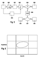
- FIG. 6 shows, as shown above, a stiffness mass diagram, in the middle field man moves, the adult in the upper right part of this field and the six-year-old child are in the lower left part.
- a ball would be assigned in the first field, ie with the lowest rigidity and the lowest mass.
- a garbage bin and a large steel post is assigned in the field above the man.
- a large steel post is assigned in the field to the right of another vehicle or a wall.
- FIG. 7 shows a signal timing diagram where the oscillation 700 is a 500 Hz oscillation and the oscillation 701 is a moving average over five values, with the moving average lagging 1 ms, which is two cycles in the present case, and allowing 98% of the signal amplitude to pass.
- FIG. 8 shows another signal timing diagram, wherein a 250 Hz oscillation 800 and a moving average 801 are shown. Again, as shown above, the moving average lags 1 ms behind, but at that frequency the moving average only allows 47% of the signal amplitude. This shows the need for signal delay or retardation.
- FIG. 9 shows a 400 Hz oscillation 90 and a moving average 91, the 400 Hz corresponding to the zero transmission frequency of a 2.5 ms window integral. After the transient, therefore, the moving average is zero, taken over five values equal to 2.5 ms.
- FIG. 10 shows a further signal timing diagram, wherein a delayed by 1 ms 250 Hz oscillation 101 and a moving average over five values equal to 2.5 ms 102 is shown.
- FIG. 11 shows a 400 Hz oscillation 110 delayed by 1 ms and a moving average over five values equal to 2.5 ms 112.
- FIG. 12 shows the result of a signal dynamics evaluation for sinusoids with frequencies of 100 Hz to 500 Hz.
- the signal corresponds to 1201 500 Hz and the signal 1209 100 Hz.
- the signals in between are each 50 Hz, starting from 100 Hz, lowered.
- FIG. 13 shows the result of a signal dynamics evaluation for sinusoids with frequencies of 100 Hz, here the lowest curve 1307, to 400 Hz are 1301.
- FIG. 14 shows the result of a signal dynamics evaluation for sinusoids with frequencies of 100 Hz 1407 to 400 Hz 1401.
- FIG. 15 shows the result of the signal dynamics evaluation according to the formula 2 for vehicle crashes: non-triggering crash 1501 against triggering crash 1502. After twenty cycles, that is 10 ms after the algorithm start, a clear separation between triggering and non-triggering crashes is possible. From this point on the evaluation is therefore robust.
- FIG. 16 shows in the upper diagram the acceleration signal of the left and the right acceleration sensor with L and R respectively. This is the test for the so-called lower leg criterion at 13.4 kg at 20 km / h.
- the diagram in the middle again shows the acceleration signal for right and left designated R and L, but this time for the steel post at 12.2 kg at 20 km / h.
- the lower diagram shows the signal dynamics estimate according to formula 7 for the two criteria, namely the curves here labeled LEG and SP for steel posts and the Lower Leg criterion respectively.
Abstract
Description
Die Erfindung betrifft ein Verfahren bzw. eine Vorrichtung zur Ansteuerung von Personenschutzmitteln nach der Gattung der unabhängigen Patentansprüche.The invention relates to a method and a device for controlling personal protection means according to the preamble of the independent claims.
Aus
Die erfindungsgemäße Vorrichtung bzw. das erfindungsgemäße Verfahren zur Ansteuerung von Personenschutzmitteln mit den Merkmalen der unabhängigen Patentansprüche haben demgegenüber den Vorteil, dass die Ansteuerungsentscheidung robuster wird und in Bezug auf Fußgängerschutzmittel eine genauere und bessere Objektunterscheidung möglich wird. Dies hängt daran, dass nunmehr die Dynamik des Unfallsignals dazu benutzt wird, die Auswertung des Unfallsignals, vorzugsweise des Beschleunigungs- oder Körperschallsignals, zu beeinflussen. Dabei kommt es zu einer Verhältnisbetrachtung von zwei Frequenzbereichen des Unfallsignals, die sich wenigstens in einem dritten Bereich unterscheiden. D. h. beispielsweise, dass der hochfrequente Anteil des Unfallsignals wird in Verhältnis gesetzt zum niederfrequenten Anteil des Unfallsignals oder zum gesamten Unfallsignal. D. h. dass sich die zwei Frequenzbereiche überlappen können, aber das zumindest ein Frequenzbereich den dritten Frequenzbereich außerhalb dieser Überlappung hat.The device according to the invention or the method according to the invention for controlling personal protection devices with the features of the independent patent claims have the advantage that the activation decision becomes more robust and a more precise and better object distinction becomes possible with respect to pedestrian protection means. This is due to the fact that now the dynamics of the accident signal is used to influence the evaluation of the accident signal, preferably the acceleration or structure-borne noise signal. This results in a ratio of two frequency ranges of the accident signal, which differ at least in a third area. Ie. For example, that the high-frequency component of the accident signal is set in relation to the low-frequency component of the accident signal or the entire accident signal. Ie. that the two frequency ranges may overlap, but that at least one frequency range has the third frequency range outside this overlap.
Es kann eine Verhältnisbildung, beispielsweise durch eine Division tatsächlich durchgeführt werden oder es wird der Nenner der Division dazu benutzt, einen Schwellwert zu bewerten und dann den Vergleich durchzuführen. Es sind jedoch auch andere Methoden möglich, um diese Verhältnisbetrachtung durchzuführen.Ratio formation, for example by division, may actually be performed, or the denominator of the division may be used to score a threshold and then make the comparison. However, other methods are also possible to perform this ratio analysis.
Der Erfindung liegt die Erkenntnis zugrunde, dass sich beispielsweise eine Steifigkeit eines Objekts in der Frequenzverteilung des bei einer Kollision auftretenden Beschleunigungssignals widerspiegelt. Die Eigenfrequenz einer Schwingung ist in einem einfachen Federmodell proportional zur Wurzel der Federkonstanten. Bei harten Objekten ist der hochfrequente Signalanteil also ausgeprägter als bei weichen Objekten. Die Auswertung der hochfrequenten Signaldynamik erlaubt daher Rückschlüsse auf die Härte des Objekts.The invention is based on the finding that, for example, a stiffness of an object is reflected in the frequency distribution of the acceleration signal occurring in the event of a collision. The natural frequency of a vibration in a simple spring model is proportional to the root of the spring constant. For hard objects, the high-frequency signal component is thus more pronounced than with soft objects. The evaluation of the high-frequency signal dynamics therefore allows conclusions about the hardness of the object.
Neben der Detektion von Fußgängern kann mit der vorliegenden Erfindung auch die Detektion von Fahrzeugcrashs verbessert werden. Auslösecrashs unterscheiden sich von Nichtauslösecrashs und Misuseobjekten häufig in der Frequenzcharakteristik, also der Signaldynamik der Unfallsignale, vorzugsweise der Beschleunigungssignale. Die Signaldynamik wird durch die Abfolge der Bruchvorgänge in der Knautschzone bestimmt. Nichtauslösecrashs weisen wegen der geringen Crashgeschwindigkeit und den daher langsamer ablaufenden Bruchvorgängen in der Regel niederfrequentere Beschleunigungssignale als Auslösecrahs auf. Auch Misuseobjekte haben häufig Frequenzcharakteristiken, die sich deutlich von Crashsignalen unterscheiden. Sie können zum einen niederfrequenter, z. B. Kieshaufen, zum Teil aber auch höherfrequenter, z. B. Hammerschläge, als Crashsignale sein.In addition to the detection of pedestrians can be improved with the present invention, the detection of vehicle crashes. Trigger crashes often differ from non-triggering crashes and misuse objects in the frequency characteristic, ie the signal dynamics of the accident signals, preferably the acceleration signals. Signal dynamics are determined by the sequence of fracture events in the crumple zone. Non-triggering crashes generally have lower-frequency acceleration signals than tripping beams because of the low crash speed and therefore the slower breaking processes. Also, misuse objects often have frequency characteristics that are significantly different from crash signals. You can for a low-frequency, z. As pebble, but in part also higher frequency, z. B. hammer blows, as crash signals.
Ziel der Erfindung ist es, diese unterschiedlichen Frequenzverteilungen im Unfallsignal, vorzugsweise Beschleunigungssignal durch Auswertung der hochfrequenten Signaldynamik zu erkennen. Für Frontcrashs am geeignetsten ist dafür beispielsweise der in Fahrtlängsrichtung empfindliche Beschleunigungssensor im zentralen Airbagsteuergerät. Es ist aber auch denkbar, die Frequenzen eines Querbeschleunigungssignals oder der sogenannten Upfrontsensoren oder der Seitenaufprallsensoren auszuwerten. Die so erhaltene Signaldynamikinformation kann dann benutzt werden, um den weiterhin auf Basis von Unfallsignalen und deren ersten und zweiten Integralen bei Beschleunigungssignalen arbeitenden Hauptalgorithmus durch Anpassung der Auslöseschwellen zu beeinflussen. Der Eingriff in den Hauptalgorithmus kann prinzipiell in derselben Weise erfolgen, wie auch sonstige Zusatzalgorithmen auf den Hauptalgorithmus einwirken.The aim of the invention is to detect these different frequency distributions in the accident signal, preferably acceleration signal by evaluating the high-frequency signal dynamics. For front crashes is most suitable for it For example, the sensitive in the driving direction acceleration sensor in the central airbag control unit. However, it is also conceivable to evaluate the frequencies of a lateral acceleration signal or the so-called upfront sensors or the side impact sensors. The signal dynamic information thus obtained can then be used to influence the main algorithm operating on the basis of accident signals and their first and second integrals in acceleration signals by adjusting the triggering thresholds. The intervention in the main algorithm can in principle take place in the same way as other additional algorithms act on the main algorithm.
Daher wird bezüglich des Fußgängerschutzes durch das erfindungsgemäße Verfahren bzw. die erfindungsgemäße Vorrichtung eine genauere und robustere Unterscheidung zwischen einem Fußgängeraufprall und Objekten, die sich von der Steifigkeit von Fußgängern unterscheiden, gewährleistet. Z. B. können so harte Objekte aus Metalls von Fußgängern unterschieden werden.Therefore, with respect to the pedestrian protection by the inventive method and the device according to the invention a more accurate and robust distinction between a pedestrian impact and objects that differ from the stiffness of pedestrians, guaranteed. For example, such hard metal objects can be distinguished from pedestrians.
Dadurch wird auf der einen Seite das Schutzpotential für Fußgänger erhöht und auf der anderen Seite die Kosten, die durch eine ungewollte Auslösung entstehen können, eingespart. Außerdem wird es verhindert, dass der Fahrer durch eine Auslösung, z. B. das Aufstellen der Fronthaube irritiert und in seinem Lenkverhalten beeinträchtigt wird.This increases the protection potential for pedestrians on the one hand and saves on the other hand the costs that can result from an unintentional triggering. In addition, it is prevented that the driver by triggering, z. B. the erection of the front panel irritated and impaired in its steering behavior.
Durch das erfindungsgemäße Verfahren wird eine genauere und robustere Unterscheidung zwischen Auslösecrashs und Nichtauslösecrashs, sowie Misuseobjekten ermöglicht. Dadurch wird das Schutzpotential von Sicherheitssteuergeräten, wie Airbagsteuergeräten, verbessert und das Risiko ungewollter Fehlauslösung weiter verringert.The inventive method enables a more accurate and robust distinction between triggering crashes and non-triggering crashes, as well as misuse objects. This improves the protection potential of safety control devices, such as airbag control units, and further reduces the risk of unwanted false tripping.
Durch die in den abhängigen Ansprüchen aufgeführten Maßnahmen und Weiterbildungen sind vorteilhafte Verbesserungen des in den unabhängigen Patentansprüchen angegebenen Verfahrens zur Ansteuerung von Personenschutzmitteln, bzw. der in den unabhängigen Patentansprüchen angegebenen Vorrichtung zur Ansteuerung von Personenschutzmitteln möglich.The measures and refinements recited in the dependent claims, advantageous improvements of the specified in the independent claims method for controlling personal protective equipment, or specified in the independent claims device for controlling personal protection means are possible.
Besonders vorteilhaft ist, dass das Verhältnis aus einem hochfrequenten und/oder einem niederfrequenten Anteil und/oder dem gesamten Unfallsignal gebildet wird. Da die Summe aus dem hochfrequenten und dem niederfrequenten Anteil das gesamte Unfallsignal ergibt, ist leicht einzusehen, dass ein jeweiliger Austausch möglich ist. Notwendig ist hierbei jedoch eine zeitliche Verzögerung des hochfrequenten bzw. gesamten Unfallsignals, um eine bessere Unterscheidung zwischen den Frequenzen zu erreiche. Weiterhin ist es vorteilhaft, dass die Dynamik des Beschleunigungssignals beziehungsweise eines hoch- oder niederfrequenten Anteils davon durch absolute Aufsummation des Beschleunigungssignals beziehungsweise eines hoch- oder niederfrequenten Anteils davon bestimmt wird. Es sind jedoch auch andere Methoden möglich.It is particularly advantageous that the ratio of a high-frequency and / or a low-frequency component and / or the entire accident signal is formed. Since the sum of the high-frequency and the low-frequency component results in the entire accident signal, it is easy to see that a respective replacement is possible. However, a time delay of the high-frequency or entire accident signal is necessary in order to achieve a better distinction between the frequencies. Furthermore, it is advantageous that the dynamics of the acceleration signal or of a high-frequency or low-frequency component thereof is determined by absolute summation of the acceleration signal or of a high-frequency or low-frequency component thereof. However, other methods are possible.
Die Beeinflussung der Auswertung kann vorteilhafter Weise dadurch erreicht werden, dass ein Schwellwert oder mehrere Schwellwerte in Abhängigkeit von dem Verhältnis verändert werden.The influencing of the evaluation can advantageously be achieved by changing one or more threshold values as a function of the ratio.
Weiterhin ist es vorteilhaft, dass die Beeinflussung in Abhängigkeit von einem Schwellwertvergleich durchgeführt wird, indem das Verhältnis mit einem Schwellwert verglichen wird. Dies kann auch unter Vermeidung einer Division, wie unten dargestellt wird, geschehen. Hier erfolgt die Bewertung durch den Schwellwertvergleich, so dass damit klar wird, ob ein Auslösefall oder ein Nichtauslösefall vorliegt oder um welches Objekt es sich bezüglich seiner Steifigkeit handelt.Furthermore, it is advantageous that the influencing is carried out as a function of a threshold value comparison by comparing the ratio with a threshold value. This can also be done while avoiding division, as shown below. Here, the evaluation is carried out by the threshold value comparison, so that it becomes clear whether a triggering case or a non-triggering case exists or which object it is with regard to its rigidity.
Weiterhin ist es vorteilhaft, dass, wenn in einem vorgegebenen Zeitfenster das erfindungsgemäße Verfahren abläuft, ein Zähler gestartet wird, der in Abhängigkeit von dem Vergleich des Verhältnisses mit dem zweiten Schwellwert inkrementiert wird. D. h. solange der zweite Schwellwert überschritten wird oder wenn er mehrfach überschritten wird, wird der Zähler inkrementiert. Erst wenn dieser Zähler einen weiteren Schwellwert übersteigt, wird die Schwellenüberschreitung des Verhältnisses akzeptiert. Dies sorgt für eine erhöhte Robustheit des Ergebnisses, denn die Signale können ein Einschwingverhalten aufweisen.Furthermore, it is advantageous that, when the method according to the invention expires within a predetermined time window, a counter is started which is incremented as a function of the comparison of the ratio with the second threshold value. Ie. as long as the second threshold is exceeded or if it is exceeded several times, the counter is incremented. Only when this counter exceeds another threshold, the threshold overrun of the ratio is accepted. This ensures an increased robustness of the result, because the signals can have a transient response.
Werden mehrere Unfallsignale von mehreren Sensoren verwendet, dann kann eine gewichtete Summe für das Verhältnis gebildet werden. Die Gewichtung kann auch in Abhängigkeit von den Signalen oder Signalanteilen durchgeführt werden. Damit kann dann beispielsweise ein Sensor, der besonders nah an der Aufprallstelle ist, besonders stark gewichtet werden.If multiple accident signals from multiple sensors are used, then a weighted sum for the ratio can be formed. The weighting can also be performed depending on the signals or signal components. Thus, for example, a sensor that is particularly close to the point of impact can be particularly heavily weighted.
Der zweite Schwellwert, der für das Verhältnis zum Vergleich herangezogen wird, kann in Abhängigkeit von einer Fahrzeuggeschwindigkeit, die beispielsweise über den CAN-Bus erhältlich ist oder eines Auftreffpunktes des Aufprallobjekts oder einer Umgebungstemperatur verändert werden. Damit kann bezüglich der Fahrzeuggeschwindigkeit auf die Unfallschwere bezüglich des Auftreffpunkts auch auf die Auswirkung bezüglich der Crashschwere und bezüglich der Umgebungstemperatur auf die Reaktion der Sensorik am Stoßfänger eingegangen werden.The second threshold value used for the ratio to the comparison may be varied depending on a vehicle speed available via, for example, the CAN bus or an impact point of the impact object or an ambient temperature. Thus, with respect to the vehicle speed on the severity of the accident with respect to the point of impact on the impact on the crash severity and with respect to the ambient temperature on the reaction of the sensors on the bumper will be discussed.
Die erfindungsgemäße Vorrichtung weist eine Schnittstelle auf, die hard- und/oder softwaremäßig ausgeführt sein kann. Diese Schnittstelle kann softwaremäßig sich als Softwaremodul auf einem Mikrocontroller und dort im Arbeitsspeicher befinden oder sie kann beispielsweise als integrierter Schaltkreis im Steuergerät angeordnet sein. An diese Schnittstelle ist dann die Unfallsensorik anschließbar. Bei der Auswerteschaltung handelt es sich üblicherweise um einen Mikrocontroller, der aber auch durch jeden anderen Prozessortyp ersetzbar ist. Auch eine andere integrierte Schaltung oder eine diskret aufgebaute Auswerteschaltung sind möglich. Auch bei der Ansteuerungsschalten kann es sich um einen integrierten Schaltkreis handeln, der Leistungsschalter aufweist und gegebenenfalls eine Logik hat, um Verknüpfungen durchzuführen. Es ist möglich, diesen integrierten Schaltkreis um diskrete Elemente zu erweitern oder völlig diskret aufzubauen.The device according to the invention has an interface which can be designed in hardware and / or software. This interface can be located in software as a software module on a microcontroller and there in the main memory or it can be arranged for example as an integrated circuit in the control unit. The accident sensors can then be connected to this interface. The evaluation circuit is usually a microcontroller, but can also be replaced by any other type of processor. Another integrated circuit or a discretely constructed evaluation circuit are possible. Also, the drive switch may be an integrated circuit having power switches and, optionally, logic to perform joins. It is possible to extend this integrated circuit by discrete elements or to build it completely discrete.
Ausführungsbeispiele der Erfindung sind in der Zeichnung dargestellt und werden in der nachfolgenden Beschreibung näher erläutert. Es zeigen:
Figur 1- ein Blockschaltbild der erfindungsgemäßen Vorrichtung,
Figur 2- Softwaremodule des Mikrocontrollers,
Figur 3- ein Flussdiagramm des erfindungsgemäßen Verfahrens,
- Figur 4
- ein erstes Signalablaufdiagramm,
Figur 5- ein zweites Signalablaufdiagramm,
- Figur 6
- ein Steifigkeit-Massediagramm,
- Figur 7
- ein erstes Signalzeitdiagramm,
- Figur 8
- ein zweites Signalzeitdiagramm,
Figur 9- ein drittes Signalzeitdiagramm,
Figur 10- ein viertes Signalzeitdiagramm,.
- Figur 11
- ein fünftes Signalzeitdiagramm,
- Figur 12
- ein sechstes Signalzeitdiagramm,
- Figur 13
- ein siebtes Signalzeitdiagramm,
- Figur 14
- ein achtes Signalzeitdiagramm,
Figur 15- ein neuntes Signalzeitdiagramm und
- Figur 16
- ein zehntes Signalzeitdiagramm.
- FIG. 1
- a block diagram of the device according to the invention,
- FIG. 2
- Software modules of the microcontroller,
- FIG. 3
- a flow chart of the method according to the invention,
- FIG. 4
- a first signal flow diagram,
- FIG. 5
- a second signal flow diagram,
- FIG. 6
- a stiffness mass diagram,
- FIG. 7
- a first signal timing diagram,
- FIG. 8
- a second signal timing diagram,
- FIG. 9
- a third signal timing diagram,
- FIG. 10
- a fourth signal timing diagram ,.
- FIG. 11
- a fifth signal timing diagram,
- FIG. 12
- a sixth signal timing diagram,
- FIG. 13
- a seventh signal timing diagram,
- FIG. 14
- an eighth signal timing diagram,
- FIG. 15
- a ninth signal timing diagram and
- FIG. 16
- a tenth signal timing diagram.
Das erfindungsgemäße Verfahren bzw. die erfindungsgemäße Vorrichtung mit den Merkmalen der unabhängigen Patentansprüche nutzen die Signaldynamik, insbesondere im hohen Frequenzbereich. Diese Signaldynamik wird dazu verwendet, um einen Ansteuerungsalgorithmus für ein Personenschutzmittel wie Airbags, Gurtstraffer, Überrollbügel oder Fußgängerschutzmittel derart zu beeinflussen, dass eine präzisere Ansteuerung erfolgt. Insbesondere sollen damit besser Nichtauslösecrashs erkannt werden. Im Folgenden wird dargelegt, wie die Erfindung funktioniert.The method according to the invention or the device according to the invention with the features of the independent patent claims make use of the signal dynamics, in particular in the high frequency range. This signal dynamics is used to influence a driving algorithm for a personal protective equipment such as airbags, belt tensioners, roll bars or pedestrian protection such that a more precise control is done. In particular, better non-triggering crashes should be recognized. The following is an explanation of how the invention works.
Der Ansatz besteht darin, ein Beschleunigungssignal α(t) mit seinem niederfrequenten Anteil a_LF(t) zu vergleichen. Der niederfrequente Anteil ist dabei durch eine Tiefpassfilterung aus dem ursprünglichen Signals α(t) zu gewinnen. Eine Möglichkeit für die Tiefpassfilterung stellt die Verwendung von gleitenden Mittelwerten über x Werte (Fensterintegrale der Länge x) dar. Die Übertragungscharakteristik der Fensterintegrale hat dabei die Besonderheit, dass die der inversen Fensterlänge entsprechende Frequenz nicht mehr übertragen wird. Beispielsweise hat ein Fensterintegral von 4ms Länge eine Nullstelle in der Übertragungsfunktion bei 250 Hz. Es ist daher vorteilhaft, den Grad der Tiefpassfilterung (im beschriebenen Beispiel über die Fensterlänge einstellbar) als Applikationsparameter variabel zu gestalten und nicht hart zu codieren.
Der hochfrequente Signalanteil ist durch a_HF(t) = a(t) - a_LF(t) gegeben. Ein relatives Maß für die Dynamik des hochfrequenten Signalanteil erhält man nun, indem man den hochfrequenten Signalanteil absolut aufsummiert und in Relation zum absolut aufsummierten Gesamtsignal setzt. 
The high-frequency signal component is given by a_HF ( t ) = a ( t ) - a_LF ( t ). A relative measure of the dynamics of the high-frequency signal component can now be obtained by summing up the high-frequency signal component in absolute terms and setting it in relation to the absolute total signal.
Die Berechnung der Absolutintegrale in Zähler und Nenner wird vorteilhafterweise erst gestartet, wenn die Startbedingung des Auslösealgorithmus überschritten wurde. Diese kann beispielsweise durch eine Schwelle auf das Beschleunigungssignal, eine Schwelle auf das Fensterintegral, oder aber durch komplexere Startbedingungen realisiert werden.The calculation of the absolute integrals in numerator and denominator is advantageously started only when the starting condition of the triggering algorithm has been exceeded. This can be realized for example by a threshold on the acceleration signal, a threshold on the window integral, or by more complex starting conditions.
Im folgenden wird beschrieben, wie der vergleichsweise einfache Ansatz (1) grundlegend verbessert werden kann.The following describes how the comparatively simple approach (1) can be fundamentally improved.
Grundlegend für das Verständnis hierfür ist, dass das tiefpassgefilterte Signal zweierlei grundsätzliche Eigenschaften besitzt:
- a) Es kann entsprechend hochfrequenten Signalen von der Größenordnung seiner Grenzfrequenz nur noch teilweise folgen (reduzierte Amplitude).
- b) Es hinkt dem Signal α(t) um eine gewisse Phasenverschiebung hinterher, im folgenden mit m Zyklen bezeichnet. Bei der Realisierung der Tiefpassfilterung über Fensterintegrale (Summe der letzten n Beschleunigungswerte) liegt das "Alter" der verwendeten Beschleunigungswerte zwischen 0 und n-1 Rechenzyklen. Das "mittlere Alter" und damit die Phasenverschiebung beträgt also bei dieser Realisierung m=(n-1)/2 Rechenzyklen. Selbst bei niederfrequenten Signalen, welche vom Tiefpassfilter fast vollständig durchgelassen werden, tritt diese Phasenverschiebung auf (siehe
Fig..7 )
- a) It can according to high-frequency signals of the order of its cutoff frequency only partially follow (reduced amplitude).
- b) It lags the signal α ( t ) by a certain phase shift, hereinafter referred to as m cycles. When implementing the low-pass filtering via window integrals (sum of the last n acceleration values), the "age" of the acceleration values used lies between 0 and n-1 computing cycles. The "mean age" and thus the phase shift is thus in this realization m = (n-1) / 2 arithmetic cycles. Even with low-frequency signals, which are almost completely transmitted by the low-pass filter, this phase shift occurs (see
Fig..7 )
Zur Bewertung des hochfrequenten Signalanteils ist allerdings nur die Eigenschaft a) von Belang. Die Eigenschaft b) sollte dagegen nicht bewertet werden, da sie eine notwendige Konsequenz der Tiefpassfilterung an sich ist.For the evaluation of the high-frequency signal component, however, only the property a) is of importance. On the other hand, property b) should not be evaluated because it is a necessary consequence of low pass filtering per se.
Dies ist in
Daher ist Formel (1) dahingehend abzuändern, dass das Signal α(t) für den Vergleich mit α_LF(t) um m Zyklen verzögert werden muss (Zwischenspeicherung). Dies soll im folgenden als retardiertes Signal bezeichnet werden, ![]()
![]()
![]()
![]()
In
Die Auswertung des Maßes (1) kann mit Verwendung des retardierten Signals aber nicht mit Algorithmusstart (Zyklus i=1) beginnen, sondern erst m Zyklen später (in Zyklus i=1+m). Anstelle von (1) erhalten wir also das wesentlich leitungsfähigere Merkmal 
Dieses Verhältnis kann nun als die "Dynamik des hochfrequenten Signalanteils" gemessen in Relation zur "Dynamik des Gesamtsignals" interpretiert werden.This ratio can now be interpreted as the "dynamics of the high-frequency signal component" measured in relation to the "dynamics of the overall signal".
Für niederfrequente Signale deutlich unter der Grenzfrequenz der Tiefpassfilterung gilt a_ret ≈ a_LF, und man erhält DevRatio ≈ 0.
Für hochfrequente Signale sinkt DevRatio ab, und für Frequenzen um die Nullübertragungsfrequenz (a_LF ≈ 0) gilt DevRatio ≈ 1.For low-frequency signals well below the cut-off frequency of low-pass filtering, a_ret ≈ a_LF holds and DevRatio ≈ 0 is obtained.
For high-frequency signals DevRatio decreases, and for frequencies around the zero-transmission frequency ( a_LF ≈ 0) DevRatio ≈ 1 applies.
Alternativ zu (2) kann nun auch die "Dynamik des hochfrequenten Signalanteils" in Relation zur "Dynamik des tieffrequenten Signalanteils" betrachtet werden, 
Für niederfrequente Signale deutlich unter der Grenzfrequenz der Tiefpassfilterung gilt α_ret ≈ α_LF, und man erhält DevRatio2 ≈ 0.
Für hochfrequente Signale sinkt DevRatio2 ab, und für Frequenzen um die Nullübertragungsfrequenz (α_LF≈0) gilt DevRatio2 → ∞.For low-frequency signals well below the cut-off frequency of low-pass filtering, α_ret ≈ α_LF , and DevRatio2 ≈ 0.
For high-frequency signals DevRatio2 decreases, and for frequencies around the zero-transmission frequency ( α_LF≈0 ) DevRatio2 → ∞.
Schlussendlich kann als Maß für die hochfrequenten Signalanteile auch die "Dynamik des Gesamtsignals" in Relation zur "Dynamik des tieffrequenten Signalanteils" betrachtet werden, 
Für hochfrequente Signale steigt Dyn an, und für Frequenzen um die Nullübertragungsfrequenz (a_LF ≈ 0) gilt Dyn → ∞.Finally, as a measure of the high-frequency signal components, the "dynamics of the overall signal" in relation to the "dynamics of the low-frequency signal component" can be considered,
For high-frequency signals, Dyn increases, and for frequencies around the zero-transmission frequency ( a _ LF ≈ 0), Dyn → ∞ applies.
Durch Vergleich von (2), (3) und (4) stellt man fest, dass die verschiedenen Kriterien die Gleichung ![]()
![]()
![]()
![]()
In
Die Kriterien (2), (3) und (4) stellen allesamt ein Verhältnis zweier Größen dar. Im Steuergerätecode bietet es sich nun an, eine Schwellwertabfrage einer solchen Größe, z.B.
nominator/denominator < Schwellwert
in der Form ![]()
nominator / denominator <threshold
in the shape ![]()
Als Beispiel für eine Signaldynamikauswertung ist in
Für die Anwendung im Bereich im Bereich Fußgängerschutz werden typischerweise 2 oder 3 Beschleunigungssensoren eingesetzt. Hier stellt sich die Problematik, wie die Signaldynamik-Abschätzungen der einzelnen Sensorsignale unter Berücksichtigung ihrer Signalstärke miteinander kombiniert werden sollen. Nach Möglichkeit soll dabei die Division in den Kriterien (2), (3) und (4) vermieden werden.For pedestrian protection applications, typically 2 or 3 accelerometers are used. This raises the problem of how the signal dynamics estimates of the individual sensor signals should be combined with one another taking into account their signal strength. If possible, the division should be avoided in the criteria (2), (3) and (4).
Diese Anforderungen werden folgendermaßen erfüllt. Das Dynamikmaß (2) angewendet auf in diesem Beispiel drei unabhängige Sensoren (links, Mitte, rechts) ergibt zunächst die drei Einzelabschätzungen 


Eine gewichtete Mittelung dieser drei Einzelkriterien ist nun so durchzuführen, dass die einzelnen Sensorsignale gemäß der "Dynamik des Gesamtsignals" gewichtet werden. Dies bedeutet, dass der Sensor mit der größten Dynamik am stärksten gewichtet wird. Damit ist sichergestellt, dass der bei einem Fußgängeraufprall nächstliegende Sensor, der typischerweise das stärkste Signal sieht, auch entsprechende stärker als die anderen Sensoren in die Signalanalyse eingeht.A weighted averaging of these three individual criteria is now to be carried out so that the individual sensor signals are weighted according to the "dynamics of the total signal". This means that the sensor with the greatest dynamics is most heavily weighted. This ensures that the sensor closest to a pedestrian impact, which typically sees the strongest signal, also enters into the signal analysis correspondingly stronger than the other sensors.
Mit den normierten Gewichtsfaktoren 
wobei die Indice i und j über die Sensorpositionen L, R, und M laufen, ergibt sich dann das Gesamtkriterium 
where the indicia i and j pass over the sensor positions L, R, and M, then the overall criterion results
Im Nenner werden die Absolutintegrale der retardierten Signale über alle Sensoren aufsummiert, im Zähler werden die Absolutintegrale der hochfrequenten Signalanteile über alle Sensoren aufsummiert.In the denominator, the absolute integrals of the delayed signals are summed over all sensors; in the numerator, the absolute integrals of the high-frequency signal components are summed over all sensors.
Da (6) wiederum ein einfacher Quotient ist, kann eine Schwellwertabfrage wieder in der Form (5) unter Vermeidung einer Division dargestellt werden.Since (6) is again a simple quotient, a threshold value query can again be represented in the form (5) while avoiding division.
Das Dynamikmaß (3) kann auf ähnliche Weise auf mehrere Sensoren erweitert werden. Die Einzelergebnisse 
Werden hier derart gewichtet, dass die einzelnen Sensorsignale gemäß der "Dynamik des niederfrequenten Signalanteils" gewichtet werden. Mit den normierten Gewichtsfaktoren 

Im Nenner werden die Absolutintegrale der niederfrequenten Signalanteile über alle Sensoren aufsummiert, im Zähler werden die Absolutintegrale der hochfrequenten Signalanteile über alle Sensoren aufsummiert.In the denominator, the absolute integrals of the low-frequency signal components are summed over all sensors; in the numerator, the absolute integrals of the high-frequency signal components are summed over all sensors.
Auch (7) ist ein einfacher Quotient, so dass eine Schwellwertabfrage wieder in der Form (5) unter Vermeidung einer Division dargestellt werden kann.Also, (7) is a simple quotient, so that a threshold value query can again be represented in the form (5) while avoiding division.
Auch die Einzelkriterien (4) mit Ergebnissen 

Im Nenner werden die Absolutintegrale der niederfrequenten Signalanteile über alle Sensoren aufsummiert, im Zähler werden die Absolutintegrale des retardierten Signals über alle Sensoren aufsummiert.In the denominator, the absolute integrals of the low-frequency signal components are summed over all sensors; in the numerator, the absolute integrals of the delayed signal are summed over all sensors.
Auch(8) ist ein einfacher Quotient, so dass eine Schwellwertabfrage wieder in der Form (5) unter Vermeidung einer Division dargestellt werden kann.Also (8) is a simple quotient, so that a threshold value query can again be represented in the form (5) while avoiding division.
In
Alle beschriebenen Kriterien (2), (3), (4) bzw. (6), (7), (8) lassen sich als Schwellwertabfragen in der Form (5) darstellen.All described criteria (2), (3), (4) or (6), (7), (8) can be represented as threshold value queries in the form (5).
Fußgängerunfälle zeichnen sich im Vergleich zu harten Misuseobjekten durch eine geringere Signaldynamik aus (siehe auch ![]()
Bei Fahrzeugcrashs haben Auslösecrashs eine höhere Signaldynamik als Nichtauslösecrashs (siehe auch ![]()
In vehicle crashes, triggering crashes have higher signal dynamics than non-triggering crashes (see also
Da alle beschriebenen Kriterien normierte Kriterien sind, ist ihre Abhängigkeit von der Zeit, nachdem sich die Berechnung nach ein paar Rechenzyklen stabilisiert hat, relativ gering. Dies ist auch aus den auf Realdaten basierten
Der Vergleich der Form (5) oder (9) sollte daher erst erfolgen, nachdem sich die Berechnung stabilisiert hat. Dies kann einfacherweise dadurch realisiert werden, dass die Schwellwertabfrage nur in einem bestimmten Zeitfenster ausgewertet wird.
Eine Stabilisierung des Kriteriums tritt typischerweise erst dann auf, wenn der Nenner ein gewisses Maß erreicht hat (Division durch zu kleine Nenner führt zu Schwankungen des Kriteriums). Daher kann alternativ oder als Ergänzung zum Zeitfenster auch ein Wertebereichsfenster für den jeweiligen Nenner verwendet werden. (Hier ist zu beachten, dass die Nenner eines jeden der Kriterien ein Absolutintegral ist und daher monoton mit der Zeit anwächst).The comparison of the form (5) or (9) should therefore only take place after the calculation has stabilized. This can be realized simply by evaluating the threshold value query only in a specific time window.
A stabilization of the criterion typically only occurs when the denominator has reached a certain degree (division by too small denominator leads to fluctuations in the criterion). Therefore, as an alternative or as a supplement to the time window, a value range window can also be used for the respective denominator. (Note that the denominator of each of the criteria is an absolute integral and thus increases monotonically with time).
Bei Fahrzeugcrashs, die sich im Gegensatz zu Fußgängerunfällen durch einen relativ gleichmäßigen Anstieg des ersten oder zweiten Integrals als Funktion der Zeit auszeichnen, kann anstelle oder als Ergänzung des Zeitfensters oder des Nenner-Wertebereichsfensters auch ein Wertebereichsfenster des ersten oder zweiten Integrals verwendet werden.In vehicle crashes which, unlike pedestrian accidents, are characterized by a relatively uniform increase in the first or second integral as a function of time, a range window of the first or second integral can also be used instead of or as a supplement to the time window or denominator range window.
Innerhalb des so definierten Auswertefensters ändern sich die beschriebenen Kriterien nur noch wenig. Es ist daher zwar denkbar, die Schwellwerte in (5) oder (9) als Funktion der Zeit oder des ersten Integrals oder des zweiten Integrals oder des jeweiligen Nenners zu variieren - in den meisten Fällen genügt aufgrund der relativen Konstanz der Kriterien aber ein fester Schwellwert. Um dabei dennoch robust gegenüber einzelne Werteabweichungen zu sein, bietet sich ein Robustheitszähler an: dabei wird innerhalb des Auswertefensters gezählt, wie häufig die Schwellwertabfrage der Form (5) oder (9) erfüllt ist. Erst nachdem der Robustheitszähler einen Schwellwert übersteigt, wird das positive Ergebnis der Signaldynamikauswertung an den Hauptalgorithmus des Fußgängerschutzsystems bzw. des Airbagsteuergerätes übergeben.Within the evaluation window defined in this way, the described criteria change only slightly. It is therefore conceivable to vary the threshold values in (5) or (9) as a function of the time or of the first integral or of the second integral or of the respective denominator - in most cases, however, a fixed threshold value is sufficient due to the relative constancy of the criteria , In order to be robust against individual value deviations, a robustness counter is recommended: within the evaluation window it is counted how often the threshold value query of the form (5) or (9) is fulfilled. Only after the robustness counter exceeds a threshold value is the positive result of the signal dynamic evaluation transferred to the main algorithm of the pedestrian protection system or the airbag control unit.
Für die Anwendung im Bereich Fußgängerschutz ist es am geeignetsten, die auf den Formeln (6), (7) oder (8) beruhende Schwellwertabfragen (5) bzw. (9) mit einem Schwellwert durchzuführen, der in Abhängigkeit von der CAN-Geschwindigkeit und/oder des erkannten Auftreffpunktes und/oder der aktuellen Umgebungstemperatur gewählt werden kann. Alternativ kann auch der Schwellwert konstant gehalten werden, und die Merkmale in Abhängigkeit von der CAN-Geschwindigkeit und/oder des erkannten Auftreffpunktes und/oder der aktuellen Umgebungstemperatur modifiziert werden.For pedestrian protection applications, it is most appropriate to use threshold value queries (5) or (9) based on formulas (6), (7) or (8) Threshold, which can be selected depending on the CAN speed and / or the detected impact point and / or the current ambient temperature. Alternatively, the threshold value can also be kept constant, and the features can be modified as a function of the CAN speed and / or the detected impact point and / or the current ambient temperature.
Die Beschleunigungssensoren BS1 bis BS4 sind an das Steuergerät SG über eine Schnittstelle IF angeschlossen. Die Schnittstelle IF ist vorliegend als integrierter Baustein ausgebildet. Es ist möglich, diese Schnittstelle diskret oder aus mehreren integrierten Bausteinen oder als Softwareschnittstelle auszubilden. Die Schnittstelle IF sorgt dafür, dass die Sensorsignale zum Mikrocontroller µC über einen sogenannten SPI- (Serial Peripherial Interface) Bus übertragen werden. Auch andere Übertragungsmöglichkeiten können genutzt werden.The acceleration sensors BS1 to BS4 are connected to the control unit SG via an interface IF. In the present case, the interface IF is designed as an integrated component. It is possible to design this interface discretely or from several integrated modules or as a software interface. The interface IF ensures that the sensor signals are transmitted to the microcontroller .mu.C via a so-called SPI (Serial Peripheral Interface) bus. Other transmission options can also be used.
Der Mikrocontroller µC verarbeitet die Beschleunigungssignale mittels des Speichers S und einem aus dem Speicher S geladenen Algorithmus. Daher weist der Speicher S flüchtige und nichtflüchtige Bereiche auf. Diese können auch getrennt ausgebildet sein. Zusätzlich verwendet der Mikrocontroller µC das Signal eines im Steuergerät SG befindlichen Beschleunigungssensors BS5, der über eine Softwareschnittstelle an den Mikrocontroller µC angebunden ist. Dabei kann die Übertragung vom Beschleunigungssensor BS5 zum Mikroncontroller µC analog oder digital ausgebildet sein, wobei bei einer analogen Übertragung der Mikrocontroller µC selbst eine Analog-Digital-Wandlung aufweist. Der Beschleunigungssensor BS5 ist in Fahrzeuglängsrichtung empfindlich. Es ist möglich, andere Empfindlichkeitsachsen zusätzlich oder anstatt zu verwenden, auch weitere Beschleunigungs- und Drehratensensoren können vorgesehen sein.The microcontroller .mu.C processes the acceleration signals by means of the memory S and an algorithm loaded from the memory S. Therefore, the memory S has volatile and non-volatile areas. These can also be separated be educated. In addition, the microcontroller μC uses the signal of an acceleration sensor BS5 located in the control unit SG, which is connected to the microcontroller μC via a software interface. In this case, the transmission from the acceleration sensor BS5 to the microcontroller .mu.C can be designed analog or digital, with the microcontroller .mu.C itself having an analog-to-digital conversion in the case of an analog transmission. The acceleration sensor BS5 is sensitive in the vehicle longitudinal direction. It is possible to use other sensitivity axes additionally or instead, also other acceleration and rotation rate sensors can be provided.
Neben den hier dargestellten Sensoren können auch Umfeldsensoren, Seitenaufprallsensoren wie Luftdrucksensoren und eine Insassensensierung vorgesehen sein, wobei diese Sensierungsmöglichkeiten ihre Daten an den Mikrocontroller µC übertragen. In Abhängigkeit von all diesen Sensorsignalen wertet der Mikrocontroller µC diese mittels seiner Algorithmen aus und erzeugt bei einem Auslösefall ein Ansteuerungssignal, das ebenfalls über den SPI-Bus an eine Ansteuerschaltung FLIC übertragen wird. In Abhängigkeit von diesem Ansteuersignal sorgt die Ansteuerschaltung FLIC für eine Auslösung der entsprechenden Personenschutzmittel PS.In addition to the sensors shown here, environmental sensors, side impact sensors such as air pressure sensors and an occupant sensor can also be provided, these sensing possibilities transmitting their data to the microcontroller .mu.C. As a function of all these sensor signals, the microcontroller μC evaluates them by means of its algorithms and, in the event of a trigger, generates a control signal which is likewise transmitted to a drive circuit FLIC via the SPI bus. In response to this drive signal, the drive circuit FLIC ensures a release of the corresponding personal protection means PS.
Der Mikrocontroller µC führt das erfindungsgemäße Verfahren aus. Dabei führt er nicht nur einen Auslösealgorithmus durch, sondern eine besondere Bewertung der Signale, indem er vorliegend das Beschleunigungssignal in zwei Frequenzbereiche aufteilt und dabei jeweils in diesen Frequenzbereichen die Dynamik bestimmt und diese Dynamiken in ein Verhältnis setzt. Dem liegt die oben genannten Erkenntnis zugrunde, dass insbesondere das hochfrequente Signal Informationen darüber hat, ob es sich um ein hartes oder weiches Objekt oder ein Nichtauslöse- oder Auslösecrash handelt. Zur Bestimmung der Dynamik des Beschleunigungssignals beziehungsweise eines hoch- oder niederfrequenten Anteils davon kann das absolut aufsummierte Beschleunigungssignal beziehungsweise eines hoch- oder niederfrequenten Anteils davon verwendet werden. Um eine bessere Trennung von Frequenzen zu erreichen ist es vorteilhaft, den hochfrequenten Anteil oder das gesamte Unfallsignal mit einer zeitlichen Verzögerung zu versehen.The microcontroller μC carries out the method according to the invention. He performs not only a triggering algorithm, but a special evaluation of the signals by dividing the acceleration signal in this case into two frequency ranges, thereby determining the dynamics in each of these frequency ranges and sets these dynamics in a ratio. This is based on the above finding that in particular the high-frequency signal has information about whether it is a hard or soft object or a non-trigger or triggering crash. To determine the dynamics of the acceleration signal or of a high-frequency or low-frequency component thereof, the absolutely accumulated acceleration signal or a high-frequency or low-frequency component thereof can be used. In order to achieve a better separation of frequencies, it is advantageous to provide the high-frequency component or the entire accident signal with a time delay.
Das Verhältnis der Dynamiken wird dann mit einem Schwellwert verglichen um zu bestimmen, ob eine Beeinflussung in Abhängigkeit von dieser Dynamikbetrachtung des Hauptauslösealgorithmus notwendig ist. Um dabei eine Division bei der Verhältnisbildung zu vermeiden, wird einfach dann der Schwellwert mit dem Nenner des Verhältnisses bewertet. Der Schwellwert kann dabei konstant oder adaptiv ausgeführt sein. Die Adaption kann in Abhängigkeit vom Beschleunigungssignal vom ersten oder zweiten Integral oder von weiteren Parametern wie der Fahrzeuggeschwindigkeit, die über den CAN-Bus ermittelbar ist, vorgenommen werden.The ratio of the dynamics is then compared to a threshold to determine if it is necessary to be influenced by this dynamics consideration of the main triggering algorithm. In order to avoid a division in the ratio formation, the threshold is then simply rated by the denominator of the ratio. The threshold value can be constant or adaptive. The adaptation can be made as a function of the acceleration signal from the first or second integral or from other parameters such as the vehicle speed, which can be determined via the CAN bus.
Um das Verfahren besonders robust auszuführen, wird ein Zähler vorgesehen, der in Abhängigkeit von diesem Schwellwertvergleich inkrementiert wird, d. h. umso öfter oder umso länger dieser Schwellwert übertroffen wird, umso mehr wird der Zähler inkrementiert. Auch dieser Zähler wird mit einem entsprechenden Schwellwert verglichen um festzustellen, ob die Verhältnisbetrachtung stabil ist.In order to carry out the method in a particularly robust manner, a counter is provided which is incremented as a function of this threshold value comparison, ie. H. the more often or the longer this threshold is exceeded, the more the counter is incremented. Also, this counter is compared with a corresponding threshold to determine if the ratio consideration is stable.
Werden wie vorliegend mehrere Sensorsignale berücksichtigt, dann werden die Dynamiken der einzelnen Sensorsignale gewichtet, und zwar in der oben angegebenen Weise.If, as in the present case, a number of sensor signals are taken into account, then the dynamics of the individual sensor signals are weighted, in the manner indicated above.
In Verfahrensschritt 404 wird dann geprüft, ob dieser Schwellwert im Block 401 überschritten wurde. Ist das nicht der Fall, dann endet in Verfahrensschritt 407 das Verfahren. Ist das jedoch der Fall, dann wird auf einen Schwellwertentscheider 406 Einfluss genommen. Dieser Schwellwertentscheider 406 wird verwendet um zu prüfen, ob ein Ansteuerungssignal erzeugt werden soll oder nicht. Dazu wird der Schwellwert mit einem verarbeiteten Beschleunigungssignal in Block 405 verglichen. Dabei kann es sich beispielsweise um das erste Integral, also ein Geschwindigkeitssignal handeln. Auch eine gewichtete Mittelung oder andere alternative Maßnahmen sind möglich, auch das zweite Integral hat sich als vorteilhaft erwiesen. In Verfahrensschritt 408 wird nun geprüft, ob der Schwellwert in Verfahrensschritt 406 überschritten wurde. Ist das nicht der Fall, dann endet das Verfahren in Verfahrensschritt 407. Wurde in Verfahrensschritt 408 festgestellt, dass der Schwellwert im Schwellwertentscheider 406 überschritten wurde, dann erfolgt die Erzeugung des Ansteuerungssignals in Verfahrensschritt 409.In
Claims (11)
Applications Claiming Priority (1)
| Application Number | Priority Date | Filing Date | Title |
|---|---|---|---|
| DE102007006769A DE102007006769A1 (en) | 2007-02-12 | 2007-02-12 | Method and device for controlling personal protective equipment |
Publications (3)
| Publication Number | Publication Date |
|---|---|
| EP1955911A2 true EP1955911A2 (en) | 2008-08-13 |
| EP1955911A3 EP1955911A3 (en) | 2010-10-13 |
| EP1955911B1 EP1955911B1 (en) | 2013-05-01 |
Family
ID=39374704
Family Applications (1)
| Application Number | Title | Priority Date | Filing Date |
|---|---|---|---|
| EP08100293.3A Expired - Fee Related EP1955911B1 (en) | 2007-02-12 | 2008-01-10 | Device and method for controlling occupant security devices |
Country Status (3)
| Country | Link |
|---|---|
| EP (1) | EP1955911B1 (en) |
| DE (1) | DE102007006769A1 (en) |
| ES (1) | ES2411057T3 (en) |
Cited By (2)
| Publication number | Priority date | Publication date | Assignee | Title |
|---|---|---|---|---|
| EP2703231A3 (en) * | 2012-09-03 | 2014-10-29 | Robert Bosch Gmbh | Sensor system for a person protection system of a vehicle and person protection system for a vehicle |
| US11541833B2 (en) * | 2019-07-08 | 2023-01-03 | Hyundai Mobis Co., Ltd. | Apparatus and method to detect crash type of vehicle |
Families Citing this family (1)
| Publication number | Priority date | Publication date | Assignee | Title |
|---|---|---|---|---|
| DE102008053622B4 (en) * | 2008-10-29 | 2010-07-29 | Autoliv Development Ab | Impact detector for distinguishing impact objects |
Citations (1)
| Publication number | Priority date | Publication date | Assignee | Title |
|---|---|---|---|---|
| DE102004042467A1 (en) | 2004-09-02 | 2006-03-09 | Robert Bosch Gmbh | Method and device for generating a triggering signal for a pedestrian protection device |
Family Cites Families (4)
| Publication number | Priority date | Publication date | Assignee | Title |
|---|---|---|---|---|
| JP3466461B2 (en) * | 1997-04-21 | 2003-11-10 | 株式会社ホンダエレシス | Method and apparatus for judging presence / absence of deformation of vehicle body side, and activation control apparatus for vehicle side occupant protection device |
| DE502004006346D1 (en) * | 2003-10-09 | 2008-04-10 | Conti Temic Microelectronic | DEVICE FOR TRIGGERING A SAFETY SYSTEM IN A VEHICLE |
| DE102005024319B3 (en) * | 2005-05-27 | 2006-12-14 | Siemens Ag | Apparatus and method for controlling a personal protection system of a vehicle |
| DE102006060277A1 (en) * | 2006-01-16 | 2007-09-20 | Continental Teves Ag & Co. Ohg | Signal preprocessing device with bandpass filters for structure-borne sound sensors |
-
2007
- 2007-02-12 DE DE102007006769A patent/DE102007006769A1/en not_active Withdrawn
-
2008
- 2008-01-10 EP EP08100293.3A patent/EP1955911B1/en not_active Expired - Fee Related
- 2008-01-10 ES ES08100293T patent/ES2411057T3/en active Active
Patent Citations (1)
| Publication number | Priority date | Publication date | Assignee | Title |
|---|---|---|---|---|
| DE102004042467A1 (en) | 2004-09-02 | 2006-03-09 | Robert Bosch Gmbh | Method and device for generating a triggering signal for a pedestrian protection device |
Cited By (2)
| Publication number | Priority date | Publication date | Assignee | Title |
|---|---|---|---|---|
| EP2703231A3 (en) * | 2012-09-03 | 2014-10-29 | Robert Bosch Gmbh | Sensor system for a person protection system of a vehicle and person protection system for a vehicle |
| US11541833B2 (en) * | 2019-07-08 | 2023-01-03 | Hyundai Mobis Co., Ltd. | Apparatus and method to detect crash type of vehicle |
Also Published As
| Publication number | Publication date |
|---|---|
| DE102007006769A1 (en) | 2008-08-14 |
| EP1955911B1 (en) | 2013-05-01 |
| ES2411057T3 (en) | 2013-07-04 |
| EP1955911A3 (en) | 2010-10-13 |
Similar Documents
| Publication | Publication Date | Title |
|---|---|---|
| DE10065518B4 (en) | Method for triggering restraint devices in a motor vehicle | |
| DE10140119C1 (en) | Impact detection device in a vehicle | |
| EP2318238B1 (en) | Method and controller for actuating personal protection means for a vehicle | |
| DE19938891B4 (en) | Method and device for controlling the deployment of a motor vehicle occupant protection system | |
| EP2066534B1 (en) | Device and method for actuating passenger protection means | |
| EP1159161A2 (en) | Method and device for controlling the deployment of an occupant-protection system of a motor vehicle | |
| EP2504201B1 (en) | Method and control unit for recognising the width of a crasharea of a vehicles front. | |
| EP3010764A1 (en) | Method and device for determining a collision characteristic of a vehicle collision | |
| EP1697177B1 (en) | Method for controlling personal protection means | |
| DE102010003333B4 (en) | Method and device for determining at least one triggering parameter of a personal protection device of a vehicle | |
| EP1863682A2 (en) | Method for generating a triggering signal for a pedestrian protection device | |
| DE10157203A1 (en) | Passive security system | |
| EP1955911B1 (en) | Device and method for controlling occupant security devices | |
| EP2996907B1 (en) | Device for controlling personal protection means in a vehicle | |
| WO2012136401A1 (en) | Method and device for evaluating structure-borne sound during a collision of a vehicle | |
| EP1034098B1 (en) | Process and device for forming a restraint system triggering criterion | |
| EP1545940B1 (en) | Arrangement for controlling retaining means | |
| WO2006012817A2 (en) | Device and method for generating an activation criterion for an impact protection system of a vehicle | |
| DE102006056836B4 (en) | Method and device for controlling personal protective equipment | |
| DE102007002274B4 (en) | Method and apparatus for offset detection of a collision for a pedestrian protection system | |
| DE102005011103B4 (en) | Method and device for detecting a rollover process | |
| EP2229295B1 (en) | Method and controller for actuating personal protection means for a vehicle | |
| DE102007017125A1 (en) | Person protection device e.g. airbag, controlling device for e.g. passenger car, involves differentiating object in vehicle surrounding based on signal from pre-crash sensors, and controlling device based on object differentiation |
Legal Events
| Date | Code | Title | Description |
|---|---|---|---|
| PUAI | Public reference made under article 153(3) epc to a published international application that has entered the european phase |
Free format text: ORIGINAL CODE: 0009012 |
|
| AK | Designated contracting states |
Kind code of ref document: A2 Designated state(s): AT BE BG CH CY CZ DE DK EE ES FI FR GB GR HR HU IE IS IT LI LT LU LV MC MT NL NO PL PT RO SE SI SK TR |
|
| AX | Request for extension of the european patent |
Extension state: AL BA MK RS |
|
| PUAL | Search report despatched |
Free format text: ORIGINAL CODE: 0009013 |
|
| AK | Designated contracting states |
Kind code of ref document: A3 Designated state(s): AT BE BG CH CY CZ DE DK EE ES FI FR GB GR HR HU IE IS IT LI LT LU LV MC MT NL NO PL PT RO SE SI SK TR |
|
| AX | Request for extension of the european patent |
Extension state: AL BA MK RS |
|
| RIC1 | Information provided on ipc code assigned before grant |
Ipc: B60R 21/0132 20060101ALI20100909BHEP Ipc: B60R 21/34 20060101AFI20080520BHEP |
|
| 17P | Request for examination filed |
Effective date: 20110413 |
|
| AKX | Designation fees paid |
Designated state(s): DE ES FR GB |
|
| GRAP | Despatch of communication of intention to grant a patent |
Free format text: ORIGINAL CODE: EPIDOSNIGR1 |
|
| GRAP | Despatch of communication of intention to grant a patent |
Free format text: ORIGINAL CODE: EPIDOSNIGR1 |
|
| GRAS | Grant fee paid |
Free format text: ORIGINAL CODE: EPIDOSNIGR3 |
|
| GRAA | (expected) grant |
Free format text: ORIGINAL CODE: 0009210 |
|
| AK | Designated contracting states |
Kind code of ref document: B1 Designated state(s): DE ES FR GB |
|
| REG | Reference to a national code |
Ref country code: GB Ref legal event code: FG4D Free format text: NOT ENGLISH |
|
| REG | Reference to a national code |
Ref country code: DE Ref legal event code: R096 Ref document number: 502008009827 Country of ref document: DE Effective date: 20130627 |
|
| REG | Reference to a national code |
Ref country code: ES Ref legal event code: FG2A Ref document number: 2411057 Country of ref document: ES Kind code of ref document: T3 Effective date: 20130704 |
|
| PLBE | No opposition filed within time limit |
Free format text: ORIGINAL CODE: 0009261 |
|
| STAA | Information on the status of an ep patent application or granted ep patent |
Free format text: STATUS: NO OPPOSITION FILED WITHIN TIME LIMIT |
|
| 26N | No opposition filed |
Effective date: 20140204 |
|
| REG | Reference to a national code |
Ref country code: DE Ref legal event code: R097 Ref document number: 502008009827 Country of ref document: DE Effective date: 20140204 |
|
| REG | Reference to a national code |
Ref country code: FR Ref legal event code: PLFP Year of fee payment: 9 |
|
| REG | Reference to a national code |
Ref country code: FR Ref legal event code: PLFP Year of fee payment: 10 |
|
| REG | Reference to a national code |
Ref country code: FR Ref legal event code: PLFP Year of fee payment: 11 |
|
| PGFP | Annual fee paid to national office [announced via postgrant information from national office to epo] |
Ref country code: ES Payment date: 20200219 Year of fee payment: 13 Ref country code: GB Payment date: 20200127 Year of fee payment: 13 |
|
| PGFP | Annual fee paid to national office [announced via postgrant information from national office to epo] |
Ref country code: FR Payment date: 20200123 Year of fee payment: 13 |
|
| PGFP | Annual fee paid to national office [announced via postgrant information from national office to epo] |
Ref country code: DE Payment date: 20210323 Year of fee payment: 14 |
|
| GBPC | Gb: european patent ceased through non-payment of renewal fee |
Effective date: 20210110 |
|
| PG25 | Lapsed in a contracting state [announced via postgrant information from national office to epo] |
Ref country code: FR Free format text: LAPSE BECAUSE OF NON-PAYMENT OF DUE FEES Effective date: 20210131 |
|
| PG25 | Lapsed in a contracting state [announced via postgrant information from national office to epo] |
Ref country code: GB Free format text: LAPSE BECAUSE OF NON-PAYMENT OF DUE FEES Effective date: 20210110 |
|
| REG | Reference to a national code |
Ref country code: ES Ref legal event code: FD2A Effective date: 20220422 |
|
| PG25 | Lapsed in a contracting state [announced via postgrant information from national office to epo] |
Ref country code: ES Free format text: LAPSE BECAUSE OF NON-PAYMENT OF DUE FEES Effective date: 20210111 |
|
| REG | Reference to a national code |
Ref country code: DE Ref legal event code: R119 Ref document number: 502008009827 Country of ref document: DE |
|
| PG25 | Lapsed in a contracting state [announced via postgrant information from national office to epo] |
Ref country code: DE Free format text: LAPSE BECAUSE OF NON-PAYMENT OF DUE FEES Effective date: 20220802 |