EP1955899A1 - Constrained layer damping for vehicle - Google Patents
Constrained layer damping for vehicle Download PDFInfo
- Publication number
- EP1955899A1 EP1955899A1 EP07002904A EP07002904A EP1955899A1 EP 1955899 A1 EP1955899 A1 EP 1955899A1 EP 07002904 A EP07002904 A EP 07002904A EP 07002904 A EP07002904 A EP 07002904A EP 1955899 A1 EP1955899 A1 EP 1955899A1
- Authority
- EP
- European Patent Office
- Prior art keywords
- damping
- layer
- floor panel
- accordance
- under floor
- Prior art date
- Legal status (The legal status is an assumption and is not a legal conclusion. Google has not performed a legal analysis and makes no representation as to the accuracy of the status listed.)
- Withdrawn
Links
- 238000013016 damping Methods 0.000 title claims abstract description 77
- 239000000463 material Substances 0.000 claims description 52
- 239000010426 asphalt Substances 0.000 claims description 12
- 125000006850 spacer group Chemical group 0.000 claims description 8
- 239000006260 foam Substances 0.000 claims description 7
- 239000006096 absorbing agent Substances 0.000 claims description 6
- 239000003562 lightweight material Substances 0.000 claims description 6
- 239000004743 Polypropylene Substances 0.000 claims description 5
- 239000013521 mastic Substances 0.000 claims description 5
- 229920001169 thermoplastic Polymers 0.000 claims description 5
- 239000004416 thermosoftening plastic Substances 0.000 claims description 5
- 125000000484 butyl group Chemical group [H]C([*])([H])C([H])([H])C([H])([H])C([H])([H])[H] 0.000 claims description 4
- 230000006835 compression Effects 0.000 claims description 4
- 238000007906 compression Methods 0.000 claims description 4
- 239000011888 foil Substances 0.000 claims description 4
- 238000003780 insertion Methods 0.000 claims description 4
- 230000037431 insertion Effects 0.000 claims description 4
- 238000010276 construction Methods 0.000 claims description 3
- 239000000835 fiber Substances 0.000 claims description 3
- 239000003365 glass fiber Substances 0.000 claims description 3
- -1 polypropylene Polymers 0.000 claims description 3
- 229920001155 polypropylene Polymers 0.000 claims description 3
- 239000004820 Pressure-sensitive adhesive Substances 0.000 claims description 2
- 239000000853 adhesive Substances 0.000 claims description 2
- 230000001070 adhesive effect Effects 0.000 claims description 2
- 239000004411 aluminium Substances 0.000 claims description 2
- XAGFODPZIPBFFR-UHFFFAOYSA-N aluminium Chemical compound [Al] XAGFODPZIPBFFR-UHFFFAOYSA-N 0.000 claims description 2
- 229910052782 aluminium Inorganic materials 0.000 claims description 2
- 238000002347 injection Methods 0.000 claims description 2
- 239000007924 injection Substances 0.000 claims description 2
- 239000010410 layer Substances 0.000 description 45
- 239000013013 elastic material Substances 0.000 description 5
- 239000002131 composite material Substances 0.000 description 2
- 230000000694 effects Effects 0.000 description 2
- 239000004033 plastic Substances 0.000 description 2
- 229920003023 plastic Polymers 0.000 description 2
- 230000005540 biological transmission Effects 0.000 description 1
- 230000007812 deficiency Effects 0.000 description 1
- 230000001419 dependent effect Effects 0.000 description 1
- 239000011256 inorganic filler Substances 0.000 description 1
- 229910003475 inorganic filler Inorganic materials 0.000 description 1
- 238000009413 insulation Methods 0.000 description 1
- 238000004519 manufacturing process Methods 0.000 description 1
- 239000012758 reinforcing additive Substances 0.000 description 1
- 239000011347 resin Substances 0.000 description 1
- 229920005989 resin Polymers 0.000 description 1
- 239000011342 resin composition Substances 0.000 description 1
- 150000003839 salts Chemical class 0.000 description 1
- 239000002356 single layer Substances 0.000 description 1
- 239000000126 substance Substances 0.000 description 1
- 229920001187 thermosetting polymer Polymers 0.000 description 1
Images


Classifications
-
- G—PHYSICS
- G10—MUSICAL INSTRUMENTS; ACOUSTICS
- G10K—SOUND-PRODUCING DEVICES; METHODS OR DEVICES FOR PROTECTING AGAINST, OR FOR DAMPING, NOISE OR OTHER ACOUSTIC WAVES IN GENERAL; ACOUSTICS NOT OTHERWISE PROVIDED FOR
- G10K11/00—Methods or devices for transmitting, conducting or directing sound in general; Methods or devices for protecting against, or for damping, noise or other acoustic waves in general
- G10K11/16—Methods or devices for protecting against, or for damping, noise or other acoustic waves in general
- G10K11/162—Selection of materials
- G10K11/168—Plural layers of different materials, e.g. sandwiches
-
- B—PERFORMING OPERATIONS; TRANSPORTING
- B60—VEHICLES IN GENERAL
- B60R—VEHICLES, VEHICLE FITTINGS, OR VEHICLE PARTS, NOT OTHERWISE PROVIDED FOR
- B60R13/00—Elements for body-finishing, identifying, or decorating; Arrangements or adaptations for advertising purposes
- B60R13/08—Insulating elements, e.g. for sound insulation
- B60R13/0861—Insulating elements, e.g. for sound insulation for covering undersurfaces of vehicles, e.g. wheel houses
-
- B—PERFORMING OPERATIONS; TRANSPORTING
- B60—VEHICLES IN GENERAL
- B60R—VEHICLES, VEHICLE FITTINGS, OR VEHICLE PARTS, NOT OTHERWISE PROVIDED FOR
- B60R13/00—Elements for body-finishing, identifying, or decorating; Arrangements or adaptations for advertising purposes
- B60R13/08—Insulating elements, e.g. for sound insulation
- B60R13/0815—Acoustic or thermal insulation of passenger compartments
- B60R13/083—Acoustic or thermal insulation of passenger compartments for fire walls or floors
Definitions
- Present invention is concerned with a damping arrangement comprising a vehicle bottom plate, an under floor panel and a damping layer in between.
- under floor panels Modern car industry more and more provides the bottom plate of the cars with under floor panels in order to protect the aggregates and components which are mounted directly underneath the bottom plate against physical and chemical damages, such as stones and salt.
- These under floor panels are usually made of plastics material and may comprise reinforcing additives, such as glass fibres. Additionally these under floor panels are used to diminish the aerodynamic resistance of the vehicle and/or to manage the heat flow directly underneath the bottom plate or underneath the motor compartment and/or to reduce the noise emission and/or transmission. Unfortunately these light weight under floor panels tend to vibrate and generate undesired noise.
- EP-1'S20'772 proposes to provide such an under floor panel with an additionally elastic material.
- This elastic material is arranged between the under floor panel and the vehicle's bottom plate and allows to combine acoustic and aerodynamic properties.
- this configuration is acoustically behaving in accordance with a classical spring-mass system, whereby the under floor panel is behaving as the mass and the elastic material as the spring.
- spring-mass systems are well known in the art and widely used for acoustic insulations.
- the disclosed configuration further allows to locally compress the elastic material in order to damp vibrations of the under floor panel. Unfortunately the local compression of the elastic material reduces the damping performance of the acoustic system at the same time. It appears that this kind of under floor construction has a limited acoustic performance.
- a constrained layer damping arrangement which is integrated in an under floor panel, comprising the features of present claim 1 and in particular comprises a vehicle bottom plate, an under floor panel and a damping layer in between, whereby the under floor panel is a constraining layer, which, together with the bottom plate and the damping layer, forms a constrained layer damper, whereby the stiffness, the loss factor and the thickness of the different layers are locally adjusted in order to optimise the overall damping performance.
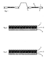
- FIG. 1 shows a schematic and cross sectional view of a damping arrangement in accordance to the invention.
- This arrangement comprises a base layer, in particular a vehicle bottom plate 1, a constraining layer, in particular an under floor panel 3 and a damping layer 2 in between. These layers are forming a constrained layer damper.
- the under floor panel 3 is spaced and affixed to the vehicle bottom plate 1 by fasteners 11, which do not exhibit particular compression forces to the constrained layer damper.
- Fig. 2 shows a schematic and cross sectional view of a constrained damper in accordance with the invention, whereby the stiffness, the loss factor and the thickness of the different layers are adjusted in order to optimize the damping performance.
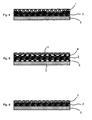
- Fig. 3 represents a preferred embodiment of present invention whereby the damping material exhibits high adhesion and/or cohesion forces in order to assure an adequate surface-to-surface bond.
- This material is chosen from butyl, sprayable bitumen, a bitumen mastic, an expandable material or is comprising a pressure sensitive adhesive foil.
- Fig. 4 shows a damping arrangement whereby the damping layer 2 comprises a locally varying thickness in order to follow the shape of the bottom plate 1. It is understood that the damping layer 2 may be assembled of patches with different thickness.
- Fig. 5 shows a damping arrangement whereby the bond between the different layers is achieved by adhesives 4, 5, which have a high shear stiffness.
- the damping arrangement shown in Fig. 6 comprises a constraining layer material 3, which is made of a stiff material in order to exhibit - during vibration - shear strains in the damping layer 2.
- the constraining layer 3 is preferably made of a fibre reinforced or non-reinforced thermoplastic fibres material and in particular of a glass fibres reinforced polypropylene material, a KEST material, a LWRT material, a JN35-material, an injection moulded PP (polypropylene) material, aluminium or a combination of these materials.
- KEST materials are well known in the art and described in W02001/40025
- LWRT Lightweight Reinforced Thermoplastic
- JN35 Advanced glass-mat thermoplastic composite applications for the automotive industry of January 2006 from Quadrant Plastic Composites
- JN35 materials are described in W02004/088025 or DE102006035361.7 .
- the damping arrangement shown in Fig. 7 concerns a layered construction in accordance with the invention, whereby the damping layer 2 is made of a standard bitumen, a butyl foil, a heavy layer bitumen, a bitumen mastic, a sprayable bitumen, or a combination of these materials.
- Fig. 8 shows a damping arrangement whereby the under floor panel 3 is partially covered by the damping layer 2 and a space 4 is created between the under floor panel 3 and the bottom plate 1.
- Fig. 9 shows a damping arrangement whereby the damping layer 2 is perforated in order to allow compression in z-direction (or an expansion of the damping material in x,y-direction) during mounting of a strip of mastic.
- Fig. 10 shows a damping arrangement whereby the layer 3 is perforated or replaced by an absorber material 7, in particular by a KEST-material, a JN35-material, a LWRT-material at areas which are not covered by the damping material 2.
- Fig. 11 shows a damping arrangement whereby the free space 4 between the bottom plate 1 and the under floor panel 3 is filled with an absorber material 6, in particular with foam, fibres material, foam chambers, ERA-material, air or similar.
- ERA material is well known in the art and by example is described in W02005/023594 or W02006/105933 .
- Fig. 12 shows a damping arrangement whereby the constraining layer 3 comprises a spacer 8 in the damped area, to assure a given distance between the under floor panel 3 and the bottom plate 1, whereby the spacer 8 is a lightweight material, e.g. a close-cell foam, or is formed by the constraining layer itself.
- the constraining layer 3 comprises a spacer 8 in the damped area, to assure a given distance between the under floor panel 3 and the bottom plate 1, whereby the spacer 8 is a lightweight material, e.g. a close-cell foam, or is formed by the constraining layer itself.
- the damping arrangement shown in Fig. 13 comprises a damping layer 2 and a spacer 8 to assure a given distance between the bottom plate 1 and the under floor panel 3, which spacer 8 is made of a lightweight material, e.g. a close-cell foam, or is made from the bottom plate material.
- a lightweight material e.g. a close-cell foam
- Fig. 14 shows a damping arrangement whereby an insertion layer 9 is arranged on the outside of the under floor panel 3 in order to smooth out the outer shape of the under floor panel 3, whereby this insertion layer 9 is made of lightweight material, e.g. absorbers material or is made from the under floor panel material itself.
- this insertion layer 9 is made of lightweight material, e.g. absorbers material or is made from the under floor panel material itself.
Landscapes
- Physics & Mathematics (AREA)
- Engineering & Computer Science (AREA)
- Acoustics & Sound (AREA)
- Multimedia (AREA)
- Mechanical Engineering (AREA)
- Vibration Prevention Devices (AREA)
- Body Structure For Vehicles (AREA)
- Laminated Bodies (AREA)
- Vehicle Interior And Exterior Ornaments, Soundproofing, And Insulation (AREA)
- Vibration Dampers (AREA)
Abstract
A vehicle bottom plate (1) is integrated into a damping arrangement comprising this vehicle bottom plate (1), an under floor panel (3) and a damping layer (2) in between. The under floor panel (3) is a constraining layer, which, together with the bottom plate (1) and the damping layer (2), forms a constrained layer damper. The stiffness, the loss factor and the thickness of the different layers are adjusted in order to optimise the damping performance.
Description
- Present invention is concerned with a damping arrangement comprising a vehicle bottom plate, an under floor panel and a damping layer in between.
- Modern car industry more and more provides the bottom plate of the cars with under floor panels in order to protect the aggregates and components which are mounted directly underneath the bottom plate against physical and chemical damages, such as stones and salt. These under floor panels are usually made of plastics material and may comprise reinforcing additives, such as glass fibres. Additionally these under floor panels are used to diminish the aerodynamic resistance of the vehicle and/or to manage the heat flow directly underneath the bottom plate or underneath the motor compartment and/or to reduce the noise emission and/or transmission. Unfortunately these light weight under floor panels tend to vibrate and generate undesired noise.
- In order to overcome these deficiencies EP-1'S20'772 proposes to provide such an under floor panel with an additionally elastic material. This elastic material is arranged between the under floor panel and the vehicle's bottom plate and allows to combine acoustic and aerodynamic properties. In particular this configuration is acoustically behaving in accordance with a classical spring-mass system, whereby the under floor panel is behaving as the mass and the elastic material as the spring. Such spring-mass systems are well known in the art and widely used for acoustic insulations. The disclosed configuration further allows to locally compress the elastic material in order to damp vibrations of the under floor panel. Unfortunately the local compression of the elastic material reduces the damping performance of the acoustic system at the same time. It appears that this kind of under floor construction has a limited acoustic performance.
- Similar disadvantages are also known from all kinds of single-layer dampers, in particular sprayable dampers, which require a rather thick deposit of damper material in order to exhibit a sufficient damping effect. This results in an undesired increase of the weight of the bottom plate and obviously causes additional assembly work and increased assembly costs.
- It is also known from EP-0'077'987 to use a constrained three-layer type damper for panels of automotive bodies, in particular for a metallic floor panel. This constrained damper comprises a meltable bonding layer, a viscoelastic layer and a constraining layer laminated such that the viscoelastic layer intimately sandwiched between the bonding layer and the constraining layer. The constraining layer of this damper is formed of a resin composition comprising an uncured thermosetting resin and an inorganic filler. Unfortunately it is not possible to easily adjust and/or optimise the damping performance of this damper.
- It is the secret of the effectivity of the damping mechanism of a constrained layer damper that during vibration the shear forces within the damping layer are increasing and thus additionally dissipating an important amount of energy.
- In view of this technical effect it is the object of present invention to achieve a vibration damping arrangement for an under floor panel, which arrangement is lightweight and simple to manufacture, which is simple to assemble and which exhibits an advanced and easy to optimise vibration damping performance.
- This object is achieved by a constrained layer damping arrangement which is integrated in an under floor panel, comprising the features of
present claim 1 and in particular comprises a vehicle bottom plate, an under floor panel and a damping layer in between, whereby the under floor panel is a constraining layer, which, together with the bottom plate and the damping layer, forms a constrained layer damper, whereby the stiffness, the loss factor and the thickness of the different layers are locally adjusted in order to optimise the overall damping performance. - It is surprising for the man skilled in the art, that thickness, loss factor and stiffness of the layers are the relevant and sufficient parameters for optimising the vibration damping performance.
- Further embodiments of the invention comprise the features of the dependent claims. All of these embodiments integrate the under floor panel into a constrained damping layer arrangement, which allows to optimise the vibration damping performance of the whole arrangement in view of the thickness, the loss factor and the stiffness of the different layers. This leads to a strong improvement of the damping performance for any given choice of materials and for any given specification. It is an additional advantage of this integrated vibration damping arrangement that the noise in the interior of the vehicle is further reduced.
- In order to exemplify the invention reference is made to the following figures illustrating:
- Fig. 1:
- a schematic and cross sectional view of a vehicle bottom plate comprising a constrained layer damping arrangement according to the invention;
- Fig. 2-6:
- a schematic and cross sectional view of the damping arrangement in accordance with the invention comprising different designs;
- Fig. 7-10:
- a schematic and cross sectional view of the damping arrangement in accordance with the invention comprising different designs of the damping layer;
- Fig. 11 - 14:
- a schematic and cross sectional view of the damping arrangement in accordance with the invention comprising different designs for an arrangement with varying thickness.
-
Figure 1 shows a schematic and cross sectional view of a damping arrangement in accordance to the invention. This arrangement comprises a base layer, in particular avehicle bottom plate 1, a constraining layer, in particular an underfloor panel 3 and adamping layer 2 in between. These layers are forming a constrained layer damper. The underfloor panel 3 is spaced and affixed to thevehicle bottom plate 1 byfasteners 11, which do not exhibit particular compression forces to the constrained layer damper. -
Fig. 2 shows a schematic and cross sectional view of a constrained damper in accordance with the invention, whereby the stiffness, the loss factor and the thickness of the different layers are adjusted in order to optimize the damping performance. -
Fig. 3 represents a preferred embodiment of present invention whereby the damping material exhibits high adhesion and/or cohesion forces in order to assure an adequate surface-to-surface bond. This material is chosen from butyl, sprayable bitumen, a bitumen mastic, an expandable material or is comprising a pressure sensitive adhesive foil. -
Fig. 4 shows a damping arrangement whereby thedamping layer 2 comprises a locally varying thickness in order to follow the shape of thebottom plate 1. It is understood that thedamping layer 2 may be assembled of patches with different thickness. -
Fig. 5 shows a damping arrangement whereby the bond between the different layers is achieved byadhesives - The damping arrangement shown in
Fig. 6 comprises a constraininglayer material 3, which is made of a stiff material in order to exhibit - during vibration - shear strains in thedamping layer 2. The constraininglayer 3 is preferably made of a fibre reinforced or non-reinforced thermoplastic fibres material and in particular of a glass fibres reinforced polypropylene material, a KEST material, a LWRT material, a JN35-material, an injection moulded PP (polypropylene) material, aluminium or a combination of these materials. KEST materials are well known in the art and described inW02001/40025 W02004/088025 orDE102006035361.7 . - The damping arrangement shown in
Fig. 7 concerns a layered construction in accordance with the invention, whereby thedamping layer 2 is made of a standard bitumen, a butyl foil, a heavy layer bitumen, a bitumen mastic, a sprayable bitumen, or a combination of these materials. -
Fig. 8 shows a damping arrangement whereby the underfloor panel 3 is partially covered by thedamping layer 2 and aspace 4 is created between the underfloor panel 3 and thebottom plate 1. -
Fig. 9 shows a damping arrangement whereby thedamping layer 2 is perforated in order to allow compression in z-direction (or an expansion of the damping material in x,y-direction) during mounting of a strip of mastic. -
Fig. 10 shows a damping arrangement whereby thelayer 3 is perforated or replaced by anabsorber material 7, in particular by a KEST-material, a JN35-material, a LWRT-material at areas which are not covered by thedamping material 2. -
Fig. 11 shows a damping arrangement whereby thefree space 4 between thebottom plate 1 and the underfloor panel 3 is filled with anabsorber material 6, in particular with foam, fibres material, foam chambers, ERA-material, air or similar. ERA material is well known in the art and by example is described inW02005/023594 orW02006/105933 . -
Fig. 12 shows a damping arrangement whereby the constraininglayer 3 comprises aspacer 8 in the damped area, to assure a given distance between the underfloor panel 3 and thebottom plate 1, whereby thespacer 8 is a lightweight material, e.g. a close-cell foam, or is formed by the constraining layer itself. - The damping arrangement shown in
Fig. 13 comprises adamping layer 2 and aspacer 8 to assure a given distance between thebottom plate 1 and the underfloor panel 3, whichspacer 8 is made of a lightweight material, e.g. a close-cell foam, or is made from the bottom plate material. -
Fig. 14 shows a damping arrangement whereby an insertion layer 9 is arranged on the outside of the underfloor panel 3 in order to smooth out the outer shape of the underfloor panel 3, whereby this insertion layer 9 is made of lightweight material, e.g. absorbers material or is made from the under floor panel material itself.
Claims (13)
- Damping arrangement comprising a vehicle bottom plate (1), an under floor panel (3) and a damping layer (2) in between, characterised in that the under floor panel (3) is a constraining layer, which, together with the bottom plate (1) and the damping layer (2), forms a constrained layer damper, whereby the stiffness, the loss factor and the thickness of the different layers are adjusted in order to optimise the damping performance.
- Damping arrangement in accordance with claim 1, characterised in that the damping material exhibits high adhesion and/or cohesion forces, and is chosen from butyl, sprayable bitumen, bitumen mastic, expandable material or is comprising a pressure sensitive adhesive foil.
- Damping arrangement in accordance with claim 1, characterised in that the damping layer (2) comprises a locally varying thickness in order to follow the shape of the floor structure or is assembled of patches with different thickness.
- Damping arrangement in accordance with claim 1, characterised in that the bonding between the different layers is achieved by adhesives (4, 5), which have a high shear stiffness.
- Damping arrangement in accordance with claim 1, characterised in that the constraining layer (3) is made of a stiff material in order to exhibit shear strains in the damping layer (2) during vibration, whereby the constraining layer (3) is fibre reinforced or non-reinforced thermoplastic fibres material, and in particular a glass fibres reinforced polypropylene, a KEST-material, a LWRT-material, a JN35-material, an injection moulded PP, an Aluminium, or a combination of these.
- Damping arrangement in accordance with claim 3, characterised in that the damping layer (2) is made of a standard bitumen, a butyl foil, a heavy layer bitumen, a bitumen mastic, a sprayable bitumen, or a combination of these materials forming a layered construction.
- Damping arrangement in accordance with claim 3, characterised in that the space (4) between the bottom plate (1) and the under floor panel (3) is partially covered by the damping layer (2).
- Damping arrangement in accordance with claim 3, characterised in that the damping layer (2) is perforated (4) in order to allow compression in z-direction, i.e. expansion of the damping material in x,y-direction, during mounting of a strip of a mastic-material.
- Damping arrangement in accordance with claim 5, characterised in that at areas not covered by the damping layer (2), the under floor panel (3) is perforated or replaced by an absorber material (7), which in particular is made from a fibre reinforced or non-reinforced thermoplastic fibres material, and in particular from a KEST-material, or a JN35-material, or a LWRT-material.
- Damping arrangement in accordance with claim 7, characterised in that the free space (4) between the bottom plate (1) and the under floor panel (3) is filled with an absorber material (6), in particular with foam, fibres material, ERA-material, air, or similar.
- Damping arrangement in accordance with claim 9, characterised in that the constraining under floor panel (3) comprises a spacer (8) in the damped area, to assure a given distance between the bottom plate (1) and the under floor panel (3), whereby the spacer (8) is made from a lightweight material, e.g. a close-cell foam, or is formed by the constraining layer itself.
- Damping arrangement in accordance with claim 9, characterised in that the damping layer (2) comprises a spacer (8) to assure a given distance between the bottom plate (1) and under floor panel (3), which spacer (8) is made of a lightweight material, e.g. a close-cell foam or is formed by the bottom plate material itself.
- Damping arrangement in accordance with claim 9, characterised in that an insertion layer (9) is arranged on the outside of the under floor panel (3) in order to smooth out the outer shape of this under floor panel (3), whereby the insertion layer (9) is made of a lightweight material, e.g. absorber material, or is made by the under floor panel material itself.
Priority Applications (10)
| Application Number | Priority Date | Filing Date | Title |
|---|---|---|---|
| EP07002904A EP1955899A1 (en) | 2007-02-12 | 2007-02-12 | Constrained layer damping for vehicle |
| PT08706357T PT2125437E (en) | 2007-02-12 | 2008-02-12 | Constrained layer damping for vehicle |
| US12/526,709 US20100013255A1 (en) | 2007-02-12 | 2008-02-12 | Constrained Layer Damping for Vehicle |
| ES08706357T ES2355865T3 (en) | 2007-02-12 | 2008-02-12 | AMORTIGUATION WITH FORCED COAT FOR VEHICLE. |
| JP2009549356A JP2010517864A (en) | 2007-02-12 | 2008-02-12 | Constrained layer damping for vehicles |
| AT08706357T ATE488403T1 (en) | 2007-02-12 | 2008-02-12 | ENCLOSED LAYER DAMPER FOR VEHICLE |
| EP08706357A EP2125437B1 (en) | 2007-02-12 | 2008-02-12 | Constrained layer damping for vehicle |
| DE602008003537T DE602008003537D1 (en) | 2007-02-12 | 2008-02-12 | DAMPER WITH INCLUDED LAYER FOR VEHICLE |
| PCT/CH2008/000052 WO2008098395A2 (en) | 2007-02-12 | 2008-02-12 | Constrained layer damping for vehicle |
| PL08706357T PL2125437T3 (en) | 2007-02-12 | 2008-02-12 | Constrained layer damping for vehicle |
Applications Claiming Priority (1)
| Application Number | Priority Date | Filing Date | Title |
|---|---|---|---|
| EP07002904A EP1955899A1 (en) | 2007-02-12 | 2007-02-12 | Constrained layer damping for vehicle |
Publications (1)
| Publication Number | Publication Date |
|---|---|
| EP1955899A1 true EP1955899A1 (en) | 2008-08-13 |
Family
ID=38164422
Family Applications (2)
| Application Number | Title | Priority Date | Filing Date |
|---|---|---|---|
| EP07002904A Withdrawn EP1955899A1 (en) | 2007-02-12 | 2007-02-12 | Constrained layer damping for vehicle |
| EP08706357A Not-in-force EP2125437B1 (en) | 2007-02-12 | 2008-02-12 | Constrained layer damping for vehicle |
Family Applications After (1)
| Application Number | Title | Priority Date | Filing Date |
|---|---|---|---|
| EP08706357A Not-in-force EP2125437B1 (en) | 2007-02-12 | 2008-02-12 | Constrained layer damping for vehicle |
Country Status (9)
| Country | Link |
|---|---|
| US (1) | US20100013255A1 (en) |
| EP (2) | EP1955899A1 (en) |
| JP (1) | JP2010517864A (en) |
| AT (1) | ATE488403T1 (en) |
| DE (1) | DE602008003537D1 (en) |
| ES (1) | ES2355865T3 (en) |
| PL (1) | PL2125437T3 (en) |
| PT (1) | PT2125437E (en) |
| WO (1) | WO2008098395A2 (en) |
Cited By (6)
| Publication number | Priority date | Publication date | Assignee | Title |
|---|---|---|---|---|
| EP2474971A1 (en) * | 2010-12-16 | 2012-07-11 | Autoneum Management AG | Constrained-layer damping material |
| WO2014168662A3 (en) * | 2013-01-17 | 2014-12-11 | Hrl Laboratories, Llc | Microlattice damping material and method for repeatable energy absorption |
| CN103262152B (en) * | 2010-12-16 | 2016-11-30 | 欧拓管理公司 | Constrained layer damping material |
| US10119589B2 (en) | 2011-08-17 | 2018-11-06 | Hrl Laboratories, Llc | Microlattice damping material and method for repeatable energy absorption |
| US11959525B2 (en) | 2018-12-25 | 2024-04-16 | Kotobukiya Fronte Co., Ltd. | Damping material |
| DE112012001388B4 (en) | 2011-03-22 | 2024-05-23 | Grouper Acquisition Company, Llc | Panel assembly with multilayer patches for sound absorption and method for its manufacture |
Families Citing this family (23)
| Publication number | Priority date | Publication date | Assignee | Title |
|---|---|---|---|---|
| US9986863B2 (en) | 2009-02-13 | 2018-06-05 | Koninklijke Philips N.V. | Floor construction with variable grade of resilience |
| JP5802210B2 (en) | 2009-10-21 | 2015-10-28 | シロー インダストリーズ インコーポレイテッド | Vehicle floor container with noise attenuation patch |
| JP5722999B2 (en) | 2010-06-16 | 2015-05-27 | シロー インダストリーズ インコーポレイテッド | Sound attenuation patch |
| US8403390B2 (en) | 2011-03-10 | 2013-03-26 | Shiloh Industries, Inc. | Vehicle panel assembly and method of attaching the same |
| JP5776450B2 (en) * | 2011-08-31 | 2015-09-09 | マツダ株式会社 | Vehicle body structure |
| US20130155547A1 (en) * | 2011-12-19 | 2013-06-20 | Hajime Eguchi | Damping material to increase a damping ratio |
| DE202012101648U1 (en) * | 2012-05-04 | 2013-08-06 | Faist Chemtec Gmbh | Sound-absorbing foil |
| US9115840B2 (en) | 2012-06-29 | 2015-08-25 | Denso International America, Inc. | Snap on vibration damper |
| US20150314363A1 (en) * | 2014-04-30 | 2015-11-05 | GM Global Technology Operations LLC | Method of forming a vehicle body structure from a pre-welded blank assembly |
| US9527370B2 (en) * | 2014-06-26 | 2016-12-27 | Ford Global Technologies, Llc | Damping and stiffening of a vehicle body panel |
| JP6341167B2 (en) * | 2015-09-07 | 2018-06-13 | トヨタ自動車株式会社 | Vehicle vibration suppression structure |
| DE102015218974A1 (en) * | 2015-09-30 | 2017-03-30 | Röchling Automotive SE & Co. KG | Vehicle floor assembly |
| US11390057B2 (en) * | 2016-06-10 | 2022-07-19 | Adco Products, Llc | Low and ultra low density butyl constrained layer patches |
| US20180073254A1 (en) * | 2016-09-14 | 2018-03-15 | Regupol America Llc | Floor tile with vibration and shock control |
| JP6369525B2 (en) * | 2016-12-07 | 2018-08-08 | マツダ株式会社 | Vehicle panel structure |
| CA3047703C (en) * | 2017-02-09 | 2023-04-25 | Fluor Technologies Corporation | Two-stage absorption for acid gas and mercaptan removal |
| DE102017123752B3 (en) | 2017-10-12 | 2019-03-07 | Dr. Ing. H.C. F. Porsche Aktiengesellschaft | Motor vehicle body part |
| EP3587851A1 (en) * | 2018-06-28 | 2020-01-01 | 3M Innovative Properties Company | Multilayer damping material |
| FR3106541B1 (en) * | 2020-01-29 | 2022-10-07 | Treves Products Services & Innovation | Acoustic protection system for motor vehicle |
| WO2021199380A1 (en) * | 2020-04-01 | 2021-10-07 | 日本製鉄株式会社 | Vehicular carbon fiber reinforced plastic composite metal plate, and vehicular panel |
| CN112092844A (en) * | 2020-10-13 | 2020-12-18 | 四川大学 | A kind of light-weight wide temperature range layered restraint damping noise reduction profile and preparation method thereof |
| EP4251420A4 (en) * | 2020-11-25 | 2024-10-09 | Nitto, Inc. | IMPROVED CONSTRAINED LAYER DAMPING MATERIALS AND SYSTEM FOR USE WITH OILY SUBSTRATES |
| JP7036474B1 (en) | 2021-07-28 | 2022-03-15 | デザインアンドイノベーション株式会社 | Laminated panel material |
Citations (7)
| Publication number | Priority date | Publication date | Assignee | Title |
|---|---|---|---|---|
| EP0077987A1 (en) * | 1981-10-24 | 1983-05-04 | Nissan Motor Co., Ltd. | Vibration damper of constrained laminate type |
| US6145617A (en) * | 1996-10-29 | 2000-11-14 | Rieter Automotive Ag | Ultra-light, multifunctional sound-insulating kit |
| US6790520B1 (en) * | 1997-11-12 | 2004-09-14 | Collins & Aikman Products Co. | Vibration dampening laminate |
| US20040253453A1 (en) * | 2003-06-11 | 2004-12-16 | Sika Corporation | Constrained layer damper |
| EP1520772A1 (en) * | 2003-10-02 | 2005-04-06 | Centre d'Etude et de Recherche pour l'Automobile ( CERA) | Underbody deflector with sound shielding properties |
| DE102004004548A1 (en) * | 2004-01-29 | 2005-08-25 | Ase-Automotive Systems Engineering Gmbh | Cladding panel for vehicle underside comprises smooth film outer face and foam backing layer corresponding to vehicle underbody |
| WO2006021004A2 (en) * | 2004-08-19 | 2006-02-23 | Diversified Chemical Technologies, Inc. | Constrained layer, composite, acoustic damping material |
Family Cites Families (22)
| Publication number | Priority date | Publication date | Assignee | Title |
|---|---|---|---|---|
| JPS6237557U (en) * | 1985-08-26 | 1987-03-05 | ||
| JPS62165043A (en) * | 1986-01-13 | 1987-07-21 | Honda Motor Co Ltd | Vibration damping material for vehicles |
| DE4413009A1 (en) * | 1994-04-15 | 1995-10-19 | Naeher Georg Gmbh | Sound absorbers for motor vehicles |
| US6454048B1 (en) * | 1998-05-12 | 2002-09-24 | Rieter Automotive (International) Ag | Acoustic insulating vehicle component |
| AR026552A1 (en) | 1999-12-03 | 2003-02-19 | Rieter Automotive Int Ag | COVERING FOR THE ROOF OF AN AUTOMOTIVE VEHICLE, AND PROCESS FOR THE MANUFACTURE OF THE SAME |
| DE10024496A1 (en) * | 2000-05-21 | 2001-11-22 | Cww Gerko Akustik Gmbh & Co Kg | Multilayered shaped component for covering regions of the vehicle base or wheel housings comprises a fleece layer which is bracketed by cover layers and forms a spring and mass system |
| PL365255A1 (en) * | 2001-05-22 | 2004-12-27 | Rieter Technologies Ag | Sound absorptive protective mat |
| DE10133425A1 (en) * | 2001-07-10 | 2003-01-30 | Hp Chem Pelzer Res & Dev Ltd | Vehicle wheel house |
| ITMI20011742A1 (en) * | 2001-08-09 | 2003-02-09 | Ilpea Ind Spa | METHOD FOR FORMING A VIBRATION SHEET OR DAMPING PANEL, AND ITS OBTAINED |
| US6799782B2 (en) * | 2002-08-08 | 2004-10-05 | International Truck Intellectual Property Company, Llc | Splash and spray suppressor |
| MXPA05010486A (en) | 2003-03-31 | 2005-11-16 | Rieter Technologies Ag | Acoustically effective nonwoven material for vehicle liners. |
| DE10332172B3 (en) * | 2003-07-15 | 2004-10-21 | Carcoustics Tech Center Gmbh | Wheel house lining for vehicles comprises three material layers having different air permeabilities at the same test pressure |
| DE20314166U1 (en) | 2003-09-11 | 2003-11-06 | Rieter Technologie Ag, Winterthur | Engine compartment absorber |
| EP1742201A4 (en) * | 2004-04-30 | 2017-07-19 | Kabushiki Kaisha Kobe Seiko Sho | Porous sound absorbing structure |
| JP2006205911A (en) * | 2005-01-28 | 2006-08-10 | Toyota Motor Corp | Vehicle sound absorber |
| JP2006240408A (en) * | 2005-03-02 | 2006-09-14 | Hirotani:Kk | Light/sound-absorbing under-cover for automobile |
| ATE427245T1 (en) | 2005-04-04 | 2009-04-15 | Rieter Technologies Ag | HERMETIC THIN MULTI-LAYER SOUND ABSORBING ELEMENT |
| JP2007001525A (en) * | 2005-06-27 | 2007-01-11 | Toyota Motor Corp | Vehicle sound absorber |
| US20110139542A1 (en) * | 2006-05-23 | 2011-06-16 | Bellmax Acoustic Pty Ltd | Acoustic shield |
| DE102006035361A1 (en) | 2006-10-19 | 2008-04-24 | Rieter Technologies Ag | Shaped article, nonwoven fabric and its manufacture and use |
| FR2912100B1 (en) * | 2007-02-06 | 2009-05-08 | Cera | ACOUSTIC PROTECTION PANEL FOR MOTOR VEHICLE COMPRISING AN IMPREGNATED SEAL LAYER |
| US7883763B2 (en) * | 2007-04-12 | 2011-02-08 | Serious Materials, Inc. | Acoustical sound proofing material with controlled water-vapor permeability and methods for manufacturing same |
-
2007
- 2007-02-12 EP EP07002904A patent/EP1955899A1/en not_active Withdrawn
-
2008
- 2008-02-12 PL PL08706357T patent/PL2125437T3/en unknown
- 2008-02-12 DE DE602008003537T patent/DE602008003537D1/en active Active
- 2008-02-12 ES ES08706357T patent/ES2355865T3/en active Active
- 2008-02-12 AT AT08706357T patent/ATE488403T1/en not_active IP Right Cessation
- 2008-02-12 JP JP2009549356A patent/JP2010517864A/en active Pending
- 2008-02-12 US US12/526,709 patent/US20100013255A1/en not_active Abandoned
- 2008-02-12 WO PCT/CH2008/000052 patent/WO2008098395A2/en not_active Ceased
- 2008-02-12 PT PT08706357T patent/PT2125437E/en unknown
- 2008-02-12 EP EP08706357A patent/EP2125437B1/en not_active Not-in-force
Patent Citations (7)
| Publication number | Priority date | Publication date | Assignee | Title |
|---|---|---|---|---|
| EP0077987A1 (en) * | 1981-10-24 | 1983-05-04 | Nissan Motor Co., Ltd. | Vibration damper of constrained laminate type |
| US6145617A (en) * | 1996-10-29 | 2000-11-14 | Rieter Automotive Ag | Ultra-light, multifunctional sound-insulating kit |
| US6790520B1 (en) * | 1997-11-12 | 2004-09-14 | Collins & Aikman Products Co. | Vibration dampening laminate |
| US20040253453A1 (en) * | 2003-06-11 | 2004-12-16 | Sika Corporation | Constrained layer damper |
| EP1520772A1 (en) * | 2003-10-02 | 2005-04-06 | Centre d'Etude et de Recherche pour l'Automobile ( CERA) | Underbody deflector with sound shielding properties |
| DE102004004548A1 (en) * | 2004-01-29 | 2005-08-25 | Ase-Automotive Systems Engineering Gmbh | Cladding panel for vehicle underside comprises smooth film outer face and foam backing layer corresponding to vehicle underbody |
| WO2006021004A2 (en) * | 2004-08-19 | 2006-02-23 | Diversified Chemical Technologies, Inc. | Constrained layer, composite, acoustic damping material |
Cited By (11)
| Publication number | Priority date | Publication date | Assignee | Title |
|---|---|---|---|---|
| EP2474971A1 (en) * | 2010-12-16 | 2012-07-11 | Autoneum Management AG | Constrained-layer damping material |
| WO2012080416A3 (en) * | 2010-12-16 | 2013-02-28 | Autoneum Management Ag | Constrained-layer damping material |
| CN103262152A (en) * | 2010-12-16 | 2013-08-21 | 欧拓管理公司 | Constrained-layer damping material |
| US9243402B2 (en) | 2010-12-16 | 2016-01-26 | Autoneum Management Ag | Constrained-layer damping material |
| CN103262152B (en) * | 2010-12-16 | 2016-11-30 | 欧拓管理公司 | Constrained layer damping material |
| DE112012001388B4 (en) | 2011-03-22 | 2024-05-23 | Grouper Acquisition Company, Llc | Panel assembly with multilayer patches for sound absorption and method for its manufacture |
| US10119589B2 (en) | 2011-08-17 | 2018-11-06 | Hrl Laboratories, Llc | Microlattice damping material and method for repeatable energy absorption |
| WO2014168662A3 (en) * | 2013-01-17 | 2014-12-11 | Hrl Laboratories, Llc | Microlattice damping material and method for repeatable energy absorption |
| CN105008759A (en) * | 2013-01-17 | 2015-10-28 | 赫尔实验室有限公司 | Microlattice damping material and method for repeatable energy absorption |
| US11959525B2 (en) | 2018-12-25 | 2024-04-16 | Kotobukiya Fronte Co., Ltd. | Damping material |
| US12467511B2 (en) | 2018-12-25 | 2025-11-11 | Kotobukiya Fronte Co., Ltd. | Damping material |
Also Published As
| Publication number | Publication date |
|---|---|
| WO2008098395A3 (en) | 2008-10-23 |
| JP2010517864A (en) | 2010-05-27 |
| DE602008003537D1 (en) | 2010-12-30 |
| ATE488403T1 (en) | 2010-12-15 |
| PL2125437T3 (en) | 2011-08-31 |
| WO2008098395A2 (en) | 2008-08-21 |
| PT2125437E (en) | 2011-02-04 |
| ES2355865T3 (en) | 2011-03-31 |
| EP2125437B1 (en) | 2010-11-17 |
| US20100013255A1 (en) | 2010-01-21 |
| EP2125437A2 (en) | 2009-12-02 |
Similar Documents
| Publication | Publication Date | Title |
|---|---|---|
| EP1955899A1 (en) | Constrained layer damping for vehicle | |
| US4308308A (en) | Multilayer anti-drumming and stiffening sheeting | |
| US11199235B2 (en) | Multilayer damping material | |
| US20150225113A1 (en) | Hybrid Noise-Insulating Structures and Applications Thereof | |
| JP5791738B2 (en) | Automotive soundproof trim parts | |
| JP2010517864A5 (en) | ||
| CN101801663A (en) | Vibration-damping composite component | |
| EP3152048B1 (en) | Device and method for deaden the sound of a component | |
| DE102011085190A1 (en) | Sound-absorbing sandwich panel | |
| NL8602132A (en) | SELF-BEARING SANDY SOUND DAMPER ELEMENT. | |
| JP4359620B2 (en) | Self-supporting body parts | |
| KR20160003186A (en) | Vehicle panel structure, roof panel and vehicle body | |
| JP4972689B2 (en) | Reduction of vibration movement | |
| ES2632293T3 (en) | Coating for noise attenuation of vibratory parts, as well as a procedure for manufacturing such a coating | |
| US9272768B2 (en) | Soundproofing cladding panel, and an aircraft | |
| US20220339912A1 (en) | Composite panel and method for manufacturing the same | |
| US20140004292A1 (en) | Composite materials | |
| EP1689617B1 (en) | Method and device for soundproofing and design therefor, especially for motor vehicles | |
| JP2706513B2 (en) | Damping sheet | |
| US20140097036A1 (en) | Multi-layer material for application to a vehicle underbody | |
| RU2449904C1 (en) | Laminar antivibration panel of driver cabin and/or car body passenger room | |
| JPH08189014A (en) | Sound absorbing body | |
| JPH02299946A (en) | Insulator dash for automobile | |
| KR20090042908A (en) | Vibration transmission reducer |
Legal Events
| Date | Code | Title | Description |
|---|---|---|---|
| PUAI | Public reference made under article 153(3) epc to a published international application that has entered the european phase |
Free format text: ORIGINAL CODE: 0009012 |
|
| AK | Designated contracting states |
Kind code of ref document: A1 Designated state(s): AT BE BG CH CY CZ DE DK EE ES FI FR GB GR HU IE IS IT LI LT LU LV MC NL PL PT RO SE SI SK TR |
|
| AX | Request for extension of the european patent |
Extension state: AL BA HR MK RS |
|
| AKX | Designation fees paid |
Designated state(s): AT BE BG CH CY CZ DE DK EE ES FI FR GB GR HU IE IS IT LI LT LU LV MC NL PL PT RO SE SI SK TR |
|
| STAA | Information on the status of an ep patent application or granted ep patent |
Free format text: STATUS: THE APPLICATION IS DEEMED TO BE WITHDRAWN |
|
| 18D | Application deemed to be withdrawn |
Effective date: 20090214 |