EP1955870A1 - Clip for writing implement - Google Patents
Clip for writing implement Download PDFInfo
- Publication number
- EP1955870A1 EP1955870A1 EP06822950A EP06822950A EP1955870A1 EP 1955870 A1 EP1955870 A1 EP 1955870A1 EP 06822950 A EP06822950 A EP 06822950A EP 06822950 A EP06822950 A EP 06822950A EP 1955870 A1 EP1955870 A1 EP 1955870A1
- Authority
- EP
- European Patent Office
- Prior art keywords
- clip
- writing implement
- cap
- ballpoint pen
- clip body
- Prior art date
- Legal status (The legal status is an assumption and is not a legal conclusion. Google has not performed a legal analysis and makes no representation as to the accuracy of the status listed.)
- Granted
Links
Images




Classifications
-
- B—PERFORMING OPERATIONS; TRANSPORTING
- B43—WRITING OR DRAWING IMPLEMENTS; BUREAU ACCESSORIES
- B43K—IMPLEMENTS FOR WRITING OR DRAWING
- B43K25/00—Attaching writing implements to wearing apparel or objects involving constructional changes of the implements
- B43K25/02—Clips
-
- B—PERFORMING OPERATIONS; TRANSPORTING
- B43—WRITING OR DRAWING IMPLEMENTS; BUREAU ACCESSORIES
- B43K—IMPLEMENTS FOR WRITING OR DRAWING
- B43K23/00—Holders or connectors for writing implements; Means for protecting the writing-points
- B43K23/08—Protecting means, e.g. caps
- B43K23/12—Protecting means, e.g. caps for pens
- B43K23/126—Protecting means, e.g. caps for pens with clips
-
- B—PERFORMING OPERATIONS; TRANSPORTING
- B43—WRITING OR DRAWING IMPLEMENTS; BUREAU ACCESSORIES
- B43K—IMPLEMENTS FOR WRITING OR DRAWING
- B43K24/00—Mechanisms for selecting, projecting, retracting or locking writing units
- B43K24/10—Mechanisms for selecting, projecting, retracting or locking writing units for selecting, projecting and locking several writing units
- B43K24/16—Mechanisms for selecting, projecting, retracting or locking writing units for selecting, projecting and locking several writing units operated by push-buttons
- B43K24/163—Mechanisms for selecting, projecting, retracting or locking writing units for selecting, projecting and locking several writing units operated by push-buttons with one push-button for each writing unit
-
- B—PERFORMING OPERATIONS; TRANSPORTING
- B43—WRITING OR DRAWING IMPLEMENTS; BUREAU ACCESSORIES
- B43K—IMPLEMENTS FOR WRITING OR DRAWING
- B43K25/00—Attaching writing implements to wearing apparel or objects involving constructional changes of the implements
- B43K25/02—Clips
- B43K25/022—Clips attached to a pen cap
-
- Y—GENERAL TAGGING OF NEW TECHNOLOGICAL DEVELOPMENTS; GENERAL TAGGING OF CROSS-SECTIONAL TECHNOLOGIES SPANNING OVER SEVERAL SECTIONS OF THE IPC; TECHNICAL SUBJECTS COVERED BY FORMER USPC CROSS-REFERENCE ART COLLECTIONS [XRACs] AND DIGESTS
- Y10—TECHNICAL SUBJECTS COVERED BY FORMER USPC
- Y10T—TECHNICAL SUBJECTS COVERED BY FORMER US CLASSIFICATION
- Y10T24/00—Buckles, buttons, clasps, etc.
- Y10T24/13—Article holder attachable to apparel or body
- Y10T24/1321—Pencil
- Y10T24/1324—Clasp attached
Definitions
- the present invention relates to a clip for a writing implement.
- a clip for a writing implement has heretofore been known, wherein the clip includes a clip body, wherein a receiving hole is formed in the clip body and a shaft body is formed on the outer surfaces of the writing implement body, wherein the shaft body is received in the receiving hole to thereby swingably couple the clip body and the writing implement body to each other, and wherein the receiving hole is sized substantially identical to the shaft body.
- a clip for a writing implement has also been known, wherein the clip includes a clip body, wherein a shaft body is attached to the clip body and a receiving hole is formed in the internal space of the writing implement body, wherein the shaft body is swingably received in the receiving hole to thereby couple the clip body and the writing implement body to each other, wherein the receiving hole is sized to be larger than the shaft body so that the clip body is able to move relative to the writing implement body while being coupled thereto, and wherein the clip includes a spring for urging the clip body toward the initial position (see JP-A-2004-190699 ).
- the clip body can move in a direction in which it separates away from the writing implement body making it possible to reliably grip an article having a large thickness.
- the receiving hole is provided in the internal space of the writing implement body, and thus the receiving hole and the shaft body are coupled to each other in the internal space.
- the internal space is so small that it is difficult to couple the clip body and the writing implement body to each other in the small internal space or, in other words, it is difficult to assemble the clip with the writing implement.
- a first invention is concerned with clip for a writing implement, wherein the clip comprises a clip body, wherein one of a clip side-coupling portion formed on the clip body and an implement side-coupling portion formed on the outer surface of the body or cap of the writing implement, is constituted by a shaft body and the other is constituted by a receiving hole, wherein the shaft body is received in the receiving hole so as to swingably couple the clip body and the body or cap of the writing implement to each other, characterized in that the receiving hole is sized to be larger than the shaft body so that the clip body is able to move relative to the body or cap of the writing implement while being coupled to the body or cap of the writing implement and that the movement of the clip body relative to the body or cap of the writing implement is limited by abutment of the shaft body against a circumferential edge of the receiving hole, and that the clip comprises a spring for urging the clip body toward the body or cap of the writing implement.
- a second invention is concerned with the first invention, wherein an operation portion is formed at a rear end of the clip body, wherein the spring is constituted by a leaf spring, and wherein an end of the leaf spring is attached to the implement side-coupling portion, or to the body or cap of the writing implement rearward of the implement side-coupling portion, and the other end of the leaf spring is attached to the clip body forward of the clip side-coupling portion.
- a third invention is concerned with the second invention, wherein a dented groove opened facing the clip body is formed in the implement side-coupling portion so that the leaf spring is able to be positioned in the dented groove.
- a fourth invention is concerned with the first invention, wherein the receiving hole is so sized that a maximum moving amount of the clip body relative to the body or cap of the writing implement is at least 0.2 times of the diameter of the shaft body.
- a fifth invention is concerned with the fourth invention, wherein the receiving hole is sized so that a maximum moving amount of the clip body relative to the body or cap of the writing implement is 0.5 times to 2 times of the diameter of the shaft body.
- the tip side of the writing implement body or the open end side of the cap is considered as a front side
- the terminal side of the writing implement body or the closed end side of the cap is considered as a rear side
- the clip can be easily assembled with the writing implement yet maintaining the action for holding an article having a large thickness.
- Figs. 1A and 1B illustrate a case where the present invention is applied to the body or cylinder of the writing implement. However, the present invention can be also applied to the cap of the writing implement.
- reference numeral 1 denotes a body of a multi-color ballpoint pen housing ink-container pipes of a plurality of colors
- 2 denotes a plurality of knock members provided on the rear side of the ballpoint pen body 1.
- the ballpoint pen body 1 is made from, for example, a synthetic resin.
- a clip 3 is arranged on the rear side of the ballpoint pen body 1 adjacent to the knock members 2.
- a convex portion 4 is formed on the outer surface 1a of the ballpoint pen body 1 integrally therewith.
- the convex portion 4 has a pair of shaft bodies 4a formed on both side surfaces thereof, and a dented groove 4b extending between the pair of shaft bodies 4a in the longitudinal axial direction and is opened facing a clip body 5.
- L-L represents the center axis of the ballpoint pen body 1
- K-K represents the center axis of the shaft bodies 4a.
- the clip 3 comprises the clip body 5 made of, for example, a synthetic resin.
- a ball portion 5a is formed at the front end of the clip body 5 integrally therewith and operation portion 5b is formed at the rear end thereof integrally therewith.
- the clip body 5 is provided with a pair of side walls 5c between the ball portion 5a and the operation portion 5b, as well as a top wall 5d connecting the side walls 5c.
- Receiving holes 5e are formed in the side walls 5c.
- the clip body 5 is sized to house the convex portion 4 in the internal space thereof defined by the side walls 5c and the top wall 5d. Upon covering the convex portion 4 with the clip body 5 while having the pair of shaft bodies 4a received in the receiving holes 5e, the clip body 5 and the ballpoint pen body 1 are swingably coupled to each other.
- a clip side-coupling portion is formed on the clip body, a implement side-coupling portion is formed on the body or cap of the writing implement, one of them is constituted by the shaft bodies and the other one is constituted by the receiving holes, and the shaft bodies are swingably received in the receiving holes so as to couple the clip body and the body or cap of the writing implement to each other.
- the receiving holes 5e are sized to be larger than the shaft bodies 4a and have an elliptic shape.
- the clip body 5 is allowed to move relative to the ballpoint pen body 1 while the shaft bodies 4a being received in the receiving holes 5e, i.e., while the clip body 5 being coupled to the ballpoint pen body 1.
- the receiving holes 5e are formed to have a longitudinal axis substantially perpendicular to the center axis L-L of the ball-point pen body 1 (see Fig. 2A ).
- the clip 3 further comprises a spring 6 of, for example, metal.
- the spring 6 is constituted by a U-shaped single leaf spring opening facing the front side.
- the rear end 6a of the leaf spring 6 is forcibly inserted and fixed in an insertion hole 4c formed in the convex portion 4, and the front end 6b of the leaf spring 6 is forcibly inserted and fixed in an insertion hole 5f formed in the clip body 5 around the ball portion 5a.
- the clip body 5 is urged by the leaf spring 6 toward the ballpoint pen body 1.
- the clip body 5 is urged by the leaf spring 6 so that the ball portion 5a abuts against the ballpoint pen body 1 and that the shaft bodies 4a abut against the top edges 5ea of the receiving holes 5e. Note that, in a natural state where the clip 3 is holding no article and no external force is acting on the clip 3, the ball portion 5a does not have to abut against the ballpoint pen body 1.
- the convex portion 4 is formed on the outer surface 1a of the ballpoint pen body 1, and the whole clip 3 inclusive of the leaf spring 6 is positioned on the outside of the ballpoint pen body 1.
- the ballpoint pen body 1 and the clip body 5 can be easily coupled to each other.
- the internal space of the ballpoint pen body 1 does not have to be expanded for the clip 3 only.
- the operation portion 5b is depressed by the user toward the ballpoint pen body 1 as indicated by an arrow X in Fig. 3A .
- the clip body 5 swings about the center axis K-K of the shaft bodies 4a ( Fig. 2C ) while the shaft bodies 4a abut against the top edges 5ea of the receiving holes 5e, the ball portion 5a separates away from the ballpoint pen body 1, and therefore, a space 7 is formed between the ball portion 5a and the ballpoint pen body 1.
- An article 8 is then inserted in the space 7. In the example shown in Fig. 3A , the article 8 is inserted so as to abut against the clip body 5.
- the clip body 5 swings about a portion 9 where the article 8 and the clip body 5 are in contact as shown in Fig. 3B .
- the shaft bodies 4a separate away from the top edges 5ea of the receiving holes 5e and move in the receiving holes 5e.
- the clip body 5 no longer swings and the shaft bodies 4a no longer move in the receiving holes 5e, i.e., the article 8 is held by the clip 3 in a state where the clip body 5 is separated away from the ballpoint pen body 1. Accordingly, the article 8 having a large thickness can be reliably held as compared to when the clip body 5 is not allowed to move relative to the ballpoint pen body 1.
- the user may exert a force as indicated by an arrow Y in Fig. 4B to the clip body 5 forward of the receiving holes 5e.
- the clip body 5 swings about a portion 10 where the clip body 5 and the ballpoint pen body 1 are in contact, and the shaft bodies 4a separate away from the top edges 5ea of the receiving holes 5e and move in the receiving holes 5e.
- the clip body 5 moves so as to separate away from the ballpoint pen body 1.
- the space 7 can be more increased than when the clip body 5 cannot be moved relative to the ballpoint pen body 1, and an article 8 having a large thickness can be reliably held.
- the receiving holes 5e have longitudinal axes substantially perpendicular to the center axis L-L of the ballpoint pen body 1.
- the longitudinal length L of the receiving holes 5e from the top edge 5ea to the bottom edge 5eb thereof defines a maximum amount P of movement of the clip body 5 relative to the ballpoint pen body 1 in the radial direction of the ballpoint pen body 1.
- the longitudinal length L of the receiving holes 5e is set to be about twice as large as the diameter D of the shaft bodies 4a (L ⁇ 2D) so that the maximum amount P of movement becomes nearly equal to the diameter D of the shaft bodies 4a.
- the receiving holes 5e is sized so that the maximum amount P of movement of the clip body 5 is at least 0.2 times of the diameter D of the shaft bodies 4a. More preferably, the receiving holes 5e is so sized that the maximum amount P of movement of the clip body 5 is 0.5 times to 2 times of the diameter D of the shaft bodies 4a.
- the longitudinal length L of the receiving holes 5e is set to be at least 1.2 times of the diameter D of the shaft bodies 4a (1.2D ⁇ L) and, preferably, 1.5 times to 3 times (1.5D ⁇ L ⁇ 3D).
- the receiving holes 5e may assume any shape so far as the clip body 5 is allowed to move relative to the ballpoint pen body 1.
- Figs. 6A to 6L illustrate other embodiments of the receiving holes 5e.
- Figs. 6C to 6G illustrate the cases where the receiving holes 5e are formed in polygonal shapes
- Figs. 6H to 6K illustrate the cases where the receiving holes 5e are formed in polygonal shapes with at least one corner or side being rounded.
- the shaft bodies 4a move about the portion 9 where the article 8 and the clip body 5 are in contact.
- the shaft bodies 4a move about the portion 10 where the clip body 5 and the ballpoint pen body 1 are in contact.
- Fig. 6L illustrates the case where the circumferential edges of the receiving holes 5e are formed along the above loci TB and TC. This assures smooth movement of the shaft bodies 4a or the clip body 5.
- the clip body 5 is urged by the leaf spring 6 in a manner that the ball portion 5a abuts against the ballpoint pen body 1 and, at the same time, the shaft bodies 4a abut against the top edges 5ea of the receiving holes 5e.
- What is needed to obtain these two urging actions is to simply attach the front end 6b of the leaf spring 6 to the clip body 5 forward of the shaft bodies 4a.
- the leaf spring 6 is lengthened and the front end 6b thereof is attached to the insertion hole 5f at the front end of the clip body 5 or around the ball portion 5a as in the embodiment of the present invention, a force to be applied to the operation portion 5b to open the clip 3 is reduced.
- the leaf spring 6 may interfere with or abut against the convex portion 4. Particularly, this tendency becomes conspicuous if the height of the shaft bodies 4a from the ballpoint pen body 1 is increased in order to increase the amount of movement of the clip body 5 relative to the ballpoint pen body 1.
- the dented groove 4b is formed in the convex portion 4, and thus the leaf spring 6 can be positioned in the dented groove 4b (see Fig. 2C ). As a result, it is allowed to increase the amount of movement of the clip body 5 while preventing the leaf spring 6 from interfering with the convex portion 4.
- the clip 3 as a whole can be formed in a compact size.
- the convex portion 4 can be easily so deformed that the shaft bodies 4a approach each other when it is attempted to have the shaft bodies 4a received in the receiving holes 5e of the clip body 5, facilitating the attachment of the clip body 5.
- the leaf spring 6 comes into engagement with the inner wall surfaces of the dented groove 4b contributing to enhancing stability of the clip body 5 in the transverse direction (direction of axis K-K, see Fig. 2C ).
- the clip body 5 does not have to be provided with the operation portion 5b as described above. However, provision of the operation portion 5b makes it easy to use it as a clip for the writing implement. Further, the clip according to the embodiment of the present invention can be easily and inexpensively produced since it includes a decreased number of parts and its mechanism is not complex.
- the spring 6 is constituted by a U-shaped single leaf spring opened toward the front side.
- the spring 6 may be, for example, a U-shaped single leaf spring opened toward the rear side.
- one end of the leaf spring is fixed in an insertion hole formed in the ballpoint pen body 1 rearward of the convex portion 4 and the other end of the leaf spring is fixed in the insertion hole formed in the clip body 5 around the operation body 5b.
Landscapes
- Clips For Writing Implements (AREA)
- Mechanical Pencils And Projecting And Retracting Systems Therefor, And Multi-System Writing Instruments (AREA)
Abstract
Description
- The present invention relates to a clip for a writing implement.
- A clip for a writing implement has heretofore been known, wherein the clip includes a clip body, wherein a receiving hole is formed in the clip body and a shaft body is formed on the outer surfaces of the writing implement body, wherein the shaft body is received in the receiving hole to thereby swingably couple the clip body and the writing implement body to each other, and wherein the receiving hole is sized substantially identical to the shaft body.
- A clip for a writing implement has also been known, wherein the clip includes a clip body, wherein a shaft body is attached to the clip body and a receiving hole is formed in the internal space of the writing implement body, wherein the shaft body is swingably received in the receiving hole to thereby couple the clip body and the writing implement body to each other, wherein the receiving hole is sized to be larger than the shaft body so that the clip body is able to move relative to the writing implement body while being coupled thereto, and wherein the clip includes a spring for urging the clip body toward the initial position (see
JP-A-2004-190699 - With the former clip for the writing implement, however, limitation is imposed on the thickness of an article that can be gripped, i.e., a problem resides in that it is difficult to reliably grip an article having a large thickness.
- With the latter clip for the writing implement, on the other hand, the clip body can move in a direction in which it separates away from the writing implement body making it possible to reliably grip an article having a large thickness. In this clip, the receiving hole is provided in the internal space of the writing implement body, and thus the receiving hole and the shaft body are coupled to each other in the internal space. Usually, however, the internal space is so small that it is difficult to couple the clip body and the writing implement body to each other in the small internal space or, in other words, it is difficult to assemble the clip with the writing implement. To begin with, it is difficult to accommodate the receiving hole and the shaft body in the small internal space. It is not realistic to expand the internal space simply for the purpose of accommodating the receiving hole and the shaft body.
- In order to solve the above problem, a first invention is concerned with clip for a writing implement, wherein the clip comprises a clip body, wherein one of a clip side-coupling portion formed on the clip body and an implement side-coupling portion formed on the outer surface of the body or cap of the writing implement, is constituted by a shaft body and the other is constituted by a receiving hole, wherein the shaft body is received in the receiving hole so as to swingably couple the clip body and the body or cap of the writing implement to each other, characterized in that the receiving hole is sized to be larger than the shaft body so that the clip body is able to move relative to the body or cap of the writing implement while being coupled to the body or cap of the writing implement and that the movement of the clip body relative to the body or cap of the writing implement is limited by abutment of the shaft body against a circumferential edge of the receiving hole, and that the clip comprises a spring for urging the clip body toward the body or cap of the writing implement.
- A second invention is concerned with the first invention, wherein an operation portion is formed at a rear end of the clip body, wherein the spring is constituted by a leaf spring, and wherein an end of the leaf spring is attached to the implement side-coupling portion, or to the body or cap of the writing implement rearward of the implement side-coupling portion, and the other end of the leaf spring is attached to the clip body forward of the clip side-coupling portion.
- A third invention is concerned with the second invention, wherein a dented groove opened facing the clip body is formed in the implement side-coupling portion so that the leaf spring is able to be positioned in the dented groove.
- A fourth invention is concerned with the first invention, wherein the receiving hole is so sized that a maximum moving amount of the clip body relative to the body or cap of the writing implement is at least 0.2 times of the diameter of the shaft body.
- A fifth invention is concerned with the fourth invention, wherein the receiving hole is sized so that a maximum moving amount of the clip body relative to the body or cap of the writing implement is 0.5 times to 2 times of the diameter of the shaft body.
- In this specification, the tip side of the writing implement body or the open end side of the cap is considered as a front side, and the terminal side of the writing implement body or the closed end side of the cap is considered as a rear side.
- According to the present invention, the clip can be easily assembled with the writing implement yet maintaining the action for holding an article having a large thickness.
-
-
Fig. 1A is a plan view of a whole ballpoint pen; -
Fig. 1B is a side view of the whole ballpoint pen; -
Fig. 2A is a side view of a clip; -
Fig. 2B is a longitudinal sectional view of the clip; -
Fig. 2C is a transverse sectional view of the clip along the line IIC-IIC; -
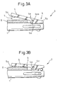
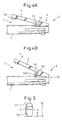
Figs. 3A, 3B ,4A and 4B are side views of the clip for illustrating an embodiment of the present invention; -
Fig. 5 is a view showing a receiving hole; and -
Figs. 6A to 6L are views showing other embodiments of the receiving hole. -
Figs. 1A and 1B illustrate a case where the present invention is applied to the body or cylinder of the writing implement. However, the present invention can be also applied to the cap of the writing implement. - Referring to
Figs. 1A and 1B ,reference numeral 1 denotes a body of a multi-color ballpoint pen housing ink-container pipes of a plurality of colors, and 2 denotes a plurality of knock members provided on the rear side of theballpoint pen body 1. When thenock member 2 is depressed by a user, a pen point of a corresponding ink-container pipe protrudes from the front end of theballpoint pen body 1 so as to be used. Theballpoint pen body 1 is made from, for example, a synthetic resin. - A
clip 3 is arranged on the rear side of theballpoint pen body 1 adjacent to theknock members 2. As closely illustrated inFigs. 2A to 2C , aconvex portion 4 is formed on theouter surface 1a of theballpoint pen body 1 integrally therewith. Theconvex portion 4 has a pair ofshaft bodies 4a formed on both side surfaces thereof, and a dented groove 4b extending between the pair ofshaft bodies 4a in the longitudinal axial direction and is opened facing aclip body 5. InFig. 2A , L-L represents the center axis of theballpoint pen body 1 and, inFig. 2C , K-K represents the center axis of theshaft bodies 4a. - The
clip 3 comprises theclip body 5 made of, for example, a synthetic resin. Aball portion 5a is formed at the front end of theclip body 5 integrally therewith andoperation portion 5b is formed at the rear end thereof integrally therewith. As will be learned, particularly, fromFig. 2C , theclip body 5 is provided with a pair ofside walls 5c between theball portion 5a and theoperation portion 5b, as well as atop wall 5d connecting theside walls 5c. Receivingholes 5e are formed in theside walls 5c. - The
clip body 5 is sized to house theconvex portion 4 in the internal space thereof defined by theside walls 5c and thetop wall 5d. Upon covering theconvex portion 4 with theclip body 5 while having the pair ofshaft bodies 4a received in the receivingholes 5e, theclip body 5 and theballpoint pen body 1 are swingably coupled to each other. - It is allowable to form the receiving holes in the
ballpoint pen body 1 and to form the shaft bodies on theclip body 5, as a matter of course. It is further allowable to form the receivingholes 5e in theside walls 5c around the rear end of theclip body 5 in a manner that theoperation portion 5b is not formed. Generally speaking, therefore, a clip side-coupling portion is formed on the clip body, a implement side-coupling portion is formed on the body or cap of the writing implement, one of them is constituted by the shaft bodies and the other one is constituted by the receiving holes, and the shaft bodies are swingably received in the receiving holes so as to couple the clip body and the body or cap of the writing implement to each other. - As shown in
Fig. 2A , in the embodiment of the present invention, the receivingholes 5e are sized to be larger than theshaft bodies 4a and have an elliptic shape. As a result, theclip body 5 is allowed to move relative to theballpoint pen body 1 while theshaft bodies 4a being received in the receivingholes 5e, i.e., while theclip body 5 being coupled to theballpoint pen body 1. In the embodiment of the present invention, thereceiving holes 5e are formed to have a longitudinal axis substantially perpendicular to the center axis L-L of the ball-point pen body 1 (seeFig. 2A ). - The
clip 3 further comprises aspring 6 of, for example, metal. In the embodiment of the present invention, thespring 6 is constituted by a U-shaped single leaf spring opening facing the front side. Therear end 6a of theleaf spring 6 is forcibly inserted and fixed in an insertion hole 4c formed in theconvex portion 4, and thefront end 6b of theleaf spring 6 is forcibly inserted and fixed in aninsertion hole 5f formed in theclip body 5 around theball portion 5a. - The
clip body 5 is urged by theleaf spring 6 toward theballpoint pen body 1. In other words, in the embodiment of the present invention as shown inFigs. 2A to 2C , theclip body 5 is urged by theleaf spring 6 so that theball portion 5a abuts against theballpoint pen body 1 and that theshaft bodies 4a abut against the top edges 5ea of the receivingholes 5e. Note that, in a natural state where theclip 3 is holding no article and no external force is acting on theclip 3, theball portion 5a does not have to abut against theballpoint pen body 1. - In the embodiment of the present invention as described above, the
convex portion 4 is formed on theouter surface 1a of theballpoint pen body 1, and thewhole clip 3 inclusive of theleaf spring 6 is positioned on the outside of theballpoint pen body 1. As a result, theballpoint pen body 1 and theclip body 5 can be easily coupled to each other. Further, the internal space of theballpoint pen body 1 does not have to be expanded for theclip 3 only. - When an article such as a document or clothing is to be gripped and held by the
clip 3, theoperation portion 5b is depressed by the user toward theballpoint pen body 1 as indicated by an arrow X inFig. 3A . As a result, theclip body 5 swings about the center axis K-K of theshaft bodies 4a (Fig. 2C ) while theshaft bodies 4a abut against the top edges 5ea of the receivingholes 5e, theball portion 5a separates away from theballpoint pen body 1, and therefore, aspace 7 is formed between theball portion 5a and theballpoint pen body 1. Anarticle 8 is then inserted in thespace 7. In the example shown inFig. 3A , thearticle 8 is inserted so as to abut against theclip body 5. Then, after the force applied to theoperation portion 5b is removed, theclip body 5 swings about aportion 9 where thearticle 8 and theclip body 5 are in contact as shown inFig. 3B . At this moment, theshaft bodies 4a separate away from the top edges 5ea of the receivingholes 5e and move in the receivingholes 5e. Thereafter, as theball portion 5a abuts against thearticle 8, theclip body 5 no longer swings and theshaft bodies 4a no longer move in the receivingholes 5e, i.e., thearticle 8 is held by theclip 3 in a state where theclip body 5 is separated away from theballpoint pen body 1. Accordingly, thearticle 8 having a large thickness can be reliably held as compared to when theclip body 5 is not allowed to move relative to theballpoint pen body 1. - Alternatively, as shown in
Fig. 4A , after theoperation portion 5b is depressed, the user may exert a force as indicated by an arrow Y inFig. 4B to theclip body 5 forward of the receivingholes 5e. In this case, theclip body 5 swings about aportion 10 where theclip body 5 and theballpoint pen body 1 are in contact, and theshaft bodies 4a separate away from the top edges 5ea of the receivingholes 5e and move in the receivingholes 5e. In other words, theclip body 5 moves so as to separate away from theballpoint pen body 1. As a result, thespace 7 can be more increased than when theclip body 5 cannot be moved relative to theballpoint pen body 1, and anarticle 8 having a large thickness can be reliably held. - Not only in the case
Figs. 3A and 3B but also in the case ofFigs. 4A and 4B , as theshaft bodies 4a abut against the bottom edges 5eb of the receivingholes 5e, limitation is posed on the movement of theclip body 5 in a direction in which it separates away from theballpoint pen body 1. When thearticle 8 is removed from theclip 3, on the other hand, theclip body 5 moves to approach theballpoint pen body 1 and, at this time, theshaft bodies 4a move in the receivingholes 5e. Then, as theball portion 5a abuts against theballpoint pen body 1 and theshaft bodies 4a abut against the top edges 5ea of the receivingholes 5e, theclip body 5 returns back to the initial position (Figs. 2A to 2C ). - In this way, the movement of the
shaft bodies 4a orclip body 5 relative to theballpoint pen body 1 is limited by the circumferential edge of the receivingholes 5e. As described above, the receivingholes 5e have longitudinal axes substantially perpendicular to the center axis L-L of theballpoint pen body 1. In this case, the longitudinal length L of the receivingholes 5e from the top edge 5ea to the bottom edge 5eb thereof defines a maximum amount P of movement of theclip body 5 relative to theballpoint pen body 1 in the radial direction of theballpoint pen body 1. In the embodiment of the present invention as shown inFig. 5 , the longitudinal length L of the receivingholes 5e is set to be about twice as large as the diameter D of theshaft bodies 4a (L≈2D) so that the maximum amount P of movement becomes nearly equal to the diameter D of theshaft bodies 4a. - Preferably, the receiving
holes 5e is sized so that the maximum amount P of movement of theclip body 5 is at least 0.2 times of the diameter D of theshaft bodies 4a. More preferably, the receivingholes 5e is so sized that the maximum amount P of movement of theclip body 5 is 0.5 times to 2 times of the diameter D of theshaft bodies 4a. Namely, in the case where the longitudinal axes of the receivingholes 5e are substantially perpendicular to the center axis L-L of theballpoint pen body 1 as shown inFigs. 2A to 2C , the longitudinal length L of the receivingholes 5e is set to be at least 1.2 times of the diameter D of theshaft bodies 4a (1.2D≤L) and, preferably, 1.5 times to 3 times (1.5D≤L≤3D). - The receiving
holes 5e may assume any shape so far as theclip body 5 is allowed to move relative to theballpoint pen body 1.Figs. 6A to 6L illustrate other embodiments of the receivingholes 5e.Figs. 6C to 6G illustrate the cases where the receivingholes 5e are formed in polygonal shapes, andFigs. 6H to 6K illustrate the cases where the receivingholes 5e are formed in polygonal shapes with at least one corner or side being rounded. In the above example ofFigs. 3A and 3B , theshaft bodies 4a move about theportion 9 where thearticle 8 and theclip body 5 are in contact. In the above example ofFigs. 4A and 4B , theshaft bodies 4a move about theportion 10 where theclip body 5 and theballpoint pen body 1 are in contact. If the locus of theshaft bodies 4a in the former example is denoted by TB and that in the latter example by TC,Fig. 6L illustrates the case where the circumferential edges of the receivingholes 5e are formed along the above loci TB and TC. This assures smooth movement of theshaft bodies 4a or theclip body 5. - As described above, the
clip body 5 is urged by theleaf spring 6 in a manner that theball portion 5a abuts against theballpoint pen body 1 and, at the same time, theshaft bodies 4a abut against the top edges 5ea of the receivingholes 5e. What is needed to obtain these two urging actions is to simply attach thefront end 6b of theleaf spring 6 to theclip body 5 forward of theshaft bodies 4a. However, if theleaf spring 6 is lengthened and thefront end 6b thereof is attached to theinsertion hole 5f at the front end of theclip body 5 or around theball portion 5a as in the embodiment of the present invention, a force to be applied to theoperation portion 5b to open theclip 3 is reduced. - In the case where the
leaf spring 6 is extended up to the front side of theshaft bodies 4a, theleaf spring 6 may interfere with or abut against theconvex portion 4. Particularly, this tendency becomes conspicuous if the height of theshaft bodies 4a from theballpoint pen body 1 is increased in order to increase the amount of movement of theclip body 5 relative to theballpoint pen body 1. In the embodiment of the present invention, however, the dented groove 4b is formed in theconvex portion 4, and thus theleaf spring 6 can be positioned in the dented groove 4b (seeFig. 2C ). As a result, it is allowed to increase the amount of movement of theclip body 5 while preventing theleaf spring 6 from interfering with theconvex portion 4. Accordingly, there is no need of providing a space for theleaf spring 6, and thus theclip 3 as a whole can be formed in a compact size. Upon forming the dented groove 4b, further, theconvex portion 4 can be easily so deformed that theshaft bodies 4a approach each other when it is attempted to have theshaft bodies 4a received in the receivingholes 5e of theclip body 5, facilitating the attachment of theclip body 5. Furthermore, while being positioned in the dented groove 4b, theleaf spring 6 comes into engagement with the inner wall surfaces of the dented groove 4b contributing to enhancing stability of theclip body 5 in the transverse direction (direction of axis K-K, seeFig. 2C ). - The
clip body 5 does not have to be provided with theoperation portion 5b as described above. However, provision of theoperation portion 5b makes it easy to use it as a clip for the writing implement. Further, the clip according to the embodiment of the present invention can be easily and inexpensively produced since it includes a decreased number of parts and its mechanism is not complex. - According to the embodiment of the present invention described above, the
spring 6 is constituted by a U-shaped single leaf spring opened toward the front side. Alternatively, thespring 6 may be, for example, a U-shaped single leaf spring opened toward the rear side. In this case, one end of the leaf spring is fixed in an insertion hole formed in theballpoint pen body 1 rearward of theconvex portion 4 and the other end of the leaf spring is fixed in the insertion hole formed in theclip body 5 around theoperation body 5b.
Claims (5)
- A clip for a writing implement, wherein the clip comprises a clip body, wherein one of a clip side-coupling portion formed on the clip body and an implement side-coupling portion formed on the outer surface of the body or cap of the writing implement, is constituted by a shaft body and the other is constituted by a receiving hole, wherein the shaft body is received in the receiving hole so as to swingably couple the clip body and the body or cap of the writing implement to each other, characterized in that the receiving hole is sized to be larger than the shaft body so that the clip body is able to move relative to the body or cap of the writing implement while being coupled to the body or cap of the writing implement and that the movement of the clip body relative to the body or cap of the writing implement is limited by abutment of the shaft body against a circumferential edge of the receiving hole, and that the clip comprises a spring for urging the clip body toward the body or cap of the writing implement.
- The clip for a writing implement according to claim 1, wherein an operation portion is formed at a rear end of the clip body, wherein the spring is constituted by a leaf spring, and wherein an end of the leaf spring is attached to the implement side-coupling portion, or to the body or cap of the writing implement rearward of the implement side-coupling portion, and the other end of the leaf spring is attached to the clip body forward of the clip side-coupling portion.
- The clip for a writing implement according to claim 2, wherein a dented groove opened facing the clip body is formed in the implement side-coupling portion so that the leaf spring is able to be positioned in the dented groove.
- The clip for a writing implement according to claim 1, wherein the receiving hole is so sized that a maximum moving amount of the clip body relative to the body or cap of the writing implement is at least 0.2 times of the diameter of the shaft body.
- The clip for a writing implement according to claim 4, wherein the receiving hole is so sized that a maximum moving amount of the clip body relative to the body or cap of the writing implement is 0.5 times to 2 times of the diameter of the shaft body.
Applications Claiming Priority (2)
| Application Number | Priority Date | Filing Date | Title |
|---|---|---|---|
| JP2005326516A JP4583291B2 (en) | 2005-11-10 | 2005-11-10 | Writing instrument clip |
| PCT/JP2006/322032 WO2007055159A1 (en) | 2005-11-10 | 2006-10-27 | Clip for writing implement |
Publications (3)
| Publication Number | Publication Date |
|---|---|
| EP1955870A1 true EP1955870A1 (en) | 2008-08-13 |
| EP1955870A4 EP1955870A4 (en) | 2009-08-05 |
| EP1955870B1 EP1955870B1 (en) | 2011-08-17 |
Family
ID=38023162
Family Applications (1)
| Application Number | Title | Priority Date | Filing Date |
|---|---|---|---|
| EP06822950A Not-in-force EP1955870B1 (en) | 2005-11-10 | 2006-10-27 | Clip for writing implement |
Country Status (5)
| Country | Link |
|---|---|
| US (1) | US20090165261A1 (en) |
| EP (1) | EP1955870B1 (en) |
| JP (1) | JP4583291B2 (en) |
| CN (1) | CN101304888B (en) |
| WO (1) | WO2007055159A1 (en) |
Cited By (1)
| Publication number | Priority date | Publication date | Assignee | Title |
|---|---|---|---|---|
| WO2012110164A1 (en) * | 2011-02-14 | 2012-08-23 | Moleskine S.R.L. | Clip |
Families Citing this family (14)
| Publication number | Priority date | Publication date | Assignee | Title |
|---|---|---|---|---|
| JP4679400B2 (en) * | 2006-03-20 | 2011-04-27 | 三菱鉛筆株式会社 | Writing instrument clip |
| JP4168088B2 (en) * | 2006-12-28 | 2008-10-22 | 東京金属工業株式会社 | clip |
| CA129102S (en) * | 2008-09-29 | 2009-07-24 | Bic Soc | Instrument d'écriture |
| JP5469495B2 (en) * | 2010-03-24 | 2014-04-16 | ゼブラ株式会社 | Writing instrument clip structure |
| JP6392298B2 (en) | 2011-12-09 | 2018-09-19 | 三菱鉛筆株式会社 | Writing instrument with eraser |
| USD701573S1 (en) * | 2012-06-08 | 2014-03-25 | Kabushiki Kaisha Pilot Corporation | Ballpoint pen |
| USD713881S1 (en) * | 2012-11-24 | 2014-09-23 | Ritter-Pen Gmbh | Ballpoint pen |
| JP6223682B2 (en) * | 2013-01-04 | 2017-11-01 | 株式会社トンボ鉛筆 | clip |
| USD772983S1 (en) * | 2015-06-10 | 2016-11-29 | Anhui Inno-Sign International Co., LTD | Pen |
| USD839347S1 (en) * | 2016-01-14 | 2019-01-29 | Pagani, S.A. | Pen |
| CA169565S (en) * | 2016-01-20 | 2017-03-10 | Pentel Kk | Ballpoint pen |
| USD806168S1 (en) * | 2016-10-13 | 2017-12-26 | Klio-Eterna Schreibgeräte Gmbh & Co Kg | Ballpoint pen |
| JP1593934S (en) * | 2016-10-23 | 2017-12-25 | ||
| USD865869S1 (en) | 2017-06-20 | 2019-11-05 | Pentel Kabushiki Kaisha | Marking pen |
Family Cites Families (21)
| Publication number | Priority date | Publication date | Assignee | Title |
|---|---|---|---|---|
| US971173A (en) * | 1909-08-21 | 1910-09-27 | George D Corey | Umbrella attachment. |
| US1016166A (en) * | 1911-04-07 | 1912-01-30 | Modern Pen Company | Pocket-clip. |
| US2500367A (en) * | 1944-09-04 | 1950-03-14 | L Heureux Gilbert | Pencil clasp |
| JPS5038678Y2 (en) * | 1971-12-09 | 1975-11-08 | ||
| US4741074A (en) * | 1987-01-07 | 1988-05-03 | Motorola, Inc. | Detachable belt clip suitable for automated assembly |
| JPH033315U (en) * | 1989-05-31 | 1991-01-14 | ||
| JP2534406Y2 (en) * | 1989-09-07 | 1997-04-30 | ニチコン株式会社 | Capacitor with security device |
| FI94582C (en) * | 1992-01-23 | 1995-09-25 | Nokia Mobile Phones Ltd | Fastener |
| US5385282A (en) * | 1994-02-28 | 1995-01-31 | Chen; Pao-Chin | Beeper holder |
| JP3003315U (en) * | 1994-04-18 | 1994-10-18 | 誠一 飯塚 | Clip binder |
| DE69520252T2 (en) * | 1994-10-18 | 2001-10-11 | Telefonaktiebolaget Lm Ericsson, Stockholm | Bracket arrangement |
| DE29611736U1 (en) * | 1996-07-05 | 1996-09-05 | Chen, Jang Mau, Panchiao, Taipeh | pen |
| JP3043721U (en) * | 1997-05-23 | 1997-11-28 | 和田 哲 | Pen with binder and clip |
| CN2304536Y (en) * | 1997-08-22 | 1999-01-20 | 简东海 | Improved Structure of Pen Holder |
| US6073318A (en) * | 1999-05-04 | 2000-06-13 | Research In Motion Limited | Retaining clip assembly |
| JP3175933B2 (en) * | 1999-11-18 | 2001-06-11 | ゼブラ株式会社 | Writing instrument clip mounting device |
| JP2004190699A (en) * | 2002-12-06 | 2004-07-08 | Sony Corp | Clip and clip clamping method |
| US6685374B1 (en) * | 2003-05-09 | 2004-02-03 | Cotapaxi, Inc. | Big clip pen |
| JP4445774B2 (en) * | 2004-02-23 | 2010-04-07 | 株式会社トンボ鉛筆 | Clip mounting structure for writing instruments |
| CN2700120Y (en) * | 2004-04-05 | 2005-05-18 | 青岛昌隆文具有限公司 | Pencil clamp capable of clamping thick articles |
| EP1847403B1 (en) * | 2004-12-28 | 2011-11-02 | Kabushiki Kaisha Pilot Corporation | Writing implement with clip member |
-
2005
- 2005-11-10 JP JP2005326516A patent/JP4583291B2/en not_active Expired - Lifetime
-
2006
- 2006-10-27 EP EP06822950A patent/EP1955870B1/en not_active Not-in-force
- 2006-10-27 US US12/084,771 patent/US20090165261A1/en not_active Abandoned
- 2006-10-27 CN CN2006800417121A patent/CN101304888B/en active Active
- 2006-10-27 WO PCT/JP2006/322032 patent/WO2007055159A1/en not_active Ceased
Cited By (1)
| Publication number | Priority date | Publication date | Assignee | Title |
|---|---|---|---|---|
| WO2012110164A1 (en) * | 2011-02-14 | 2012-08-23 | Moleskine S.R.L. | Clip |
Also Published As
| Publication number | Publication date |
|---|---|
| WO2007055159A1 (en) | 2007-05-18 |
| CN101304888A (en) | 2008-11-12 |
| CN101304888B (en) | 2011-06-15 |
| JP2007130900A (en) | 2007-05-31 |
| JP4583291B2 (en) | 2010-11-17 |
| US20090165261A1 (en) | 2009-07-02 |
| EP1955870A4 (en) | 2009-08-05 |
| EP1955870B1 (en) | 2011-08-17 |
Similar Documents
| Publication | Publication Date | Title |
|---|---|---|
| EP1955870A1 (en) | Clip for writing implement | |
| JP2001010277A (en) | Writing instrument barrel | |
| US20110180676A1 (en) | Clipping structure for writing instrument | |
| CN114222668B (en) | retractable writing instrument | |
| JP4679400B2 (en) | Writing instrument clip | |
| JP3121560U (en) | Touch pen | |
| JP4822354B2 (en) | Sliding writing instrument with clip | |
| JP3680433B2 (en) | Multi-core writing instrument | |
| JP2008188966A (en) | Sliding writing instrument with clip | |
| JP3767888B2 (en) | Sliding composite writing instrument including mechanical pencil | |
| KR101539396B1 (en) | Ball pen | |
| JP4562187B2 (en) | Swing-out mechanical pencil | |
| JP3150466U (en) | Metal clip | |
| JP3653699B2 (en) | Knock-type writing instrument | |
| JP3982386B2 (en) | mechanical pencil | |
| JP2000127678A (en) | Knock type writing instrument | |
| JP4444692B2 (en) | Knock-type writing instrument having a clip member | |
| JP4863491B2 (en) | Writing instrument | |
| JP2598110Y2 (en) | Side knock type writing instrument | |
| KR870002713Y1 (en) | Shaaf Pencil | |
| JPH0746554Y2 (en) | Writing instrument | |
| JPH0746553Y2 (en) | Writing instrument | |
| JP2025134518A (en) | Knock-type writing implement | |
| KR880001959Y1 (en) | Double sharp pencil | |
| JP3951827B2 (en) | Core holding structure |
Legal Events
| Date | Code | Title | Description |
|---|---|---|---|
| PUAI | Public reference made under article 153(3) epc to a published international application that has entered the european phase |
Free format text: ORIGINAL CODE: 0009012 |
|
| 17P | Request for examination filed |
Effective date: 20080505 |
|
| AK | Designated contracting states |
Kind code of ref document: A1 Designated state(s): AT BE BG CH CY CZ DE DK EE ES FI FR GB GR HU IE IS IT LI LT LU LV MC NL PL PT RO SE SI SK TR |
|
| A4 | Supplementary search report drawn up and despatched |
Effective date: 20090706 |
|
| 17Q | First examination report despatched |
Effective date: 20091014 |
|
| GRAP | Despatch of communication of intention to grant a patent |
Free format text: ORIGINAL CODE: EPIDOSNIGR1 |
|
| GRAC | Information related to communication of intention to grant a patent modified |
Free format text: ORIGINAL CODE: EPIDOSCIGR1 |
|
| DAX | Request for extension of the european patent (deleted) | ||
| GRAS | Grant fee paid |
Free format text: ORIGINAL CODE: EPIDOSNIGR3 |
|
| GRAA | (expected) grant |
Free format text: ORIGINAL CODE: 0009210 |
|
| AK | Designated contracting states |
Kind code of ref document: B1 Designated state(s): AT BE BG CH CY CZ DE DK EE ES FI FR GB GR HU IE IS IT LI LT LU LV MC NL PL PT RO SE SI SK TR |
|
| REG | Reference to a national code |
Ref country code: GB Ref legal event code: FG4D |
|
| REG | Reference to a national code |
Ref country code: CH Ref legal event code: EP |
|
| REG | Reference to a national code |
Ref country code: IE Ref legal event code: FG4D |
|
| REG | Reference to a national code |
Ref country code: DE Ref legal event code: R096 Ref document number: 602006023899 Country of ref document: DE Effective date: 20111013 |
|
| REG | Reference to a national code |
Ref country code: NL Ref legal event code: VDEP Effective date: 20110817 |
|
| LTIE | Lt: invalidation of european patent or patent extension |
Effective date: 20110817 |
|
| PG25 | Lapsed in a contracting state [announced via postgrant information from national office to epo] |
Ref country code: NL Free format text: LAPSE BECAUSE OF FAILURE TO SUBMIT A TRANSLATION OF THE DESCRIPTION OR TO PAY THE FEE WITHIN THE PRESCRIBED TIME-LIMIT Effective date: 20110817 Ref country code: PT Free format text: LAPSE BECAUSE OF FAILURE TO SUBMIT A TRANSLATION OF THE DESCRIPTION OR TO PAY THE FEE WITHIN THE PRESCRIBED TIME-LIMIT Effective date: 20111219 Ref country code: SE Free format text: LAPSE BECAUSE OF FAILURE TO SUBMIT A TRANSLATION OF THE DESCRIPTION OR TO PAY THE FEE WITHIN THE PRESCRIBED TIME-LIMIT Effective date: 20110817 Ref country code: FI Free format text: LAPSE BECAUSE OF FAILURE TO SUBMIT A TRANSLATION OF THE DESCRIPTION OR TO PAY THE FEE WITHIN THE PRESCRIBED TIME-LIMIT Effective date: 20110817 Ref country code: IS Free format text: LAPSE BECAUSE OF FAILURE TO SUBMIT A TRANSLATION OF THE DESCRIPTION OR TO PAY THE FEE WITHIN THE PRESCRIBED TIME-LIMIT Effective date: 20111217 Ref country code: LT Free format text: LAPSE BECAUSE OF FAILURE TO SUBMIT A TRANSLATION OF THE DESCRIPTION OR TO PAY THE FEE WITHIN THE PRESCRIBED TIME-LIMIT Effective date: 20110817 |
|
| REG | Reference to a national code |
Ref country code: AT Ref legal event code: MK05 Ref document number: 520544 Country of ref document: AT Kind code of ref document: T Effective date: 20110817 |
|
| PG25 | Lapsed in a contracting state [announced via postgrant information from national office to epo] |
Ref country code: PL Free format text: LAPSE BECAUSE OF FAILURE TO SUBMIT A TRANSLATION OF THE DESCRIPTION OR TO PAY THE FEE WITHIN THE PRESCRIBED TIME-LIMIT Effective date: 20110817 Ref country code: LV Free format text: LAPSE BECAUSE OF FAILURE TO SUBMIT A TRANSLATION OF THE DESCRIPTION OR TO PAY THE FEE WITHIN THE PRESCRIBED TIME-LIMIT Effective date: 20110817 Ref country code: SI Free format text: LAPSE BECAUSE OF FAILURE TO SUBMIT A TRANSLATION OF THE DESCRIPTION OR TO PAY THE FEE WITHIN THE PRESCRIBED TIME-LIMIT Effective date: 20110817 Ref country code: CY Free format text: LAPSE BECAUSE OF FAILURE TO SUBMIT A TRANSLATION OF THE DESCRIPTION OR TO PAY THE FEE WITHIN THE PRESCRIBED TIME-LIMIT Effective date: 20110817 Ref country code: AT Free format text: LAPSE BECAUSE OF FAILURE TO SUBMIT A TRANSLATION OF THE DESCRIPTION OR TO PAY THE FEE WITHIN THE PRESCRIBED TIME-LIMIT Effective date: 20110817 Ref country code: GR Free format text: LAPSE BECAUSE OF FAILURE TO SUBMIT A TRANSLATION OF THE DESCRIPTION OR TO PAY THE FEE WITHIN THE PRESCRIBED TIME-LIMIT Effective date: 20111118 |
|
| PG25 | Lapsed in a contracting state [announced via postgrant information from national office to epo] |
Ref country code: BE Free format text: LAPSE BECAUSE OF FAILURE TO SUBMIT A TRANSLATION OF THE DESCRIPTION OR TO PAY THE FEE WITHIN THE PRESCRIBED TIME-LIMIT Effective date: 20110817 |
|
| PG25 | Lapsed in a contracting state [announced via postgrant information from national office to epo] |
Ref country code: SK Free format text: LAPSE BECAUSE OF FAILURE TO SUBMIT A TRANSLATION OF THE DESCRIPTION OR TO PAY THE FEE WITHIN THE PRESCRIBED TIME-LIMIT Effective date: 20110817 Ref country code: CZ Free format text: LAPSE BECAUSE OF FAILURE TO SUBMIT A TRANSLATION OF THE DESCRIPTION OR TO PAY THE FEE WITHIN THE PRESCRIBED TIME-LIMIT Effective date: 20110817 |
|
| PG25 | Lapsed in a contracting state [announced via postgrant information from national office to epo] |
Ref country code: MC Free format text: LAPSE BECAUSE OF NON-PAYMENT OF DUE FEES Effective date: 20111031 Ref country code: EE Free format text: LAPSE BECAUSE OF FAILURE TO SUBMIT A TRANSLATION OF THE DESCRIPTION OR TO PAY THE FEE WITHIN THE PRESCRIBED TIME-LIMIT Effective date: 20110817 Ref country code: IT Free format text: LAPSE BECAUSE OF FAILURE TO SUBMIT A TRANSLATION OF THE DESCRIPTION OR TO PAY THE FEE WITHIN THE PRESCRIBED TIME-LIMIT Effective date: 20110817 Ref country code: RO Free format text: LAPSE BECAUSE OF FAILURE TO SUBMIT A TRANSLATION OF THE DESCRIPTION OR TO PAY THE FEE WITHIN THE PRESCRIBED TIME-LIMIT Effective date: 20110817 |
|
| REG | Reference to a national code |
Ref country code: CH Ref legal event code: PL |
|
| PLBE | No opposition filed within time limit |
Free format text: ORIGINAL CODE: 0009261 |
|
| STAA | Information on the status of an ep patent application or granted ep patent |
Free format text: STATUS: NO OPPOSITION FILED WITHIN TIME LIMIT |
|
| PG25 | Lapsed in a contracting state [announced via postgrant information from national office to epo] |
Ref country code: DK Free format text: LAPSE BECAUSE OF FAILURE TO SUBMIT A TRANSLATION OF THE DESCRIPTION OR TO PAY THE FEE WITHIN THE PRESCRIBED TIME-LIMIT Effective date: 20110817 |
|
| 26N | No opposition filed |
Effective date: 20120521 |
|
| PG25 | Lapsed in a contracting state [announced via postgrant information from national office to epo] |
Ref country code: LI Free format text: LAPSE BECAUSE OF NON-PAYMENT OF DUE FEES Effective date: 20111031 Ref country code: DE Free format text: LAPSE BECAUSE OF NON-PAYMENT OF DUE FEES Effective date: 20120501 Ref country code: CH Free format text: LAPSE BECAUSE OF NON-PAYMENT OF DUE FEES Effective date: 20111031 |
|
| REG | Reference to a national code |
Ref country code: IE Ref legal event code: MM4A |
|
| REG | Reference to a national code |
Ref country code: DE Ref legal event code: R119 Ref document number: 602006023899 Country of ref document: DE Effective date: 20120501 |
|
| PG25 | Lapsed in a contracting state [announced via postgrant information from national office to epo] |
Ref country code: IE Free format text: LAPSE BECAUSE OF NON-PAYMENT OF DUE FEES Effective date: 20111027 |
|
| PG25 | Lapsed in a contracting state [announced via postgrant information from national office to epo] |
Ref country code: ES Free format text: LAPSE BECAUSE OF FAILURE TO SUBMIT A TRANSLATION OF THE DESCRIPTION OR TO PAY THE FEE WITHIN THE PRESCRIBED TIME-LIMIT Effective date: 20111128 |
|
| PG25 | Lapsed in a contracting state [announced via postgrant information from national office to epo] |
Ref country code: LU Free format text: LAPSE BECAUSE OF NON-PAYMENT OF DUE FEES Effective date: 20111027 |
|
| PG25 | Lapsed in a contracting state [announced via postgrant information from national office to epo] |
Ref country code: BG Free format text: LAPSE BECAUSE OF FAILURE TO SUBMIT A TRANSLATION OF THE DESCRIPTION OR TO PAY THE FEE WITHIN THE PRESCRIBED TIME-LIMIT Effective date: 20111117 |
|
| PG25 | Lapsed in a contracting state [announced via postgrant information from national office to epo] |
Ref country code: TR Free format text: LAPSE BECAUSE OF FAILURE TO SUBMIT A TRANSLATION OF THE DESCRIPTION OR TO PAY THE FEE WITHIN THE PRESCRIBED TIME-LIMIT Effective date: 20110817 |
|
| PG25 | Lapsed in a contracting state [announced via postgrant information from national office to epo] |
Ref country code: HU Free format text: LAPSE BECAUSE OF FAILURE TO SUBMIT A TRANSLATION OF THE DESCRIPTION OR TO PAY THE FEE WITHIN THE PRESCRIBED TIME-LIMIT Effective date: 20110817 |
|
| REG | Reference to a national code |
Ref country code: FR Ref legal event code: PLFP Year of fee payment: 11 |
|
| PGFP | Annual fee paid to national office [announced via postgrant information from national office to epo] |
Ref country code: FR Payment date: 20160919 Year of fee payment: 11 |
|
| PGFP | Annual fee paid to national office [announced via postgrant information from national office to epo] |
Ref country code: GB Payment date: 20161026 Year of fee payment: 11 |
|
| GBPC | Gb: european patent ceased through non-payment of renewal fee |
Effective date: 20171027 |
|
| REG | Reference to a national code |
Ref country code: FR Ref legal event code: ST Effective date: 20180629 |
|
| PG25 | Lapsed in a contracting state [announced via postgrant information from national office to epo] |
Ref country code: GB Free format text: LAPSE BECAUSE OF NON-PAYMENT OF DUE FEES Effective date: 20171027 |
|
| PG25 | Lapsed in a contracting state [announced via postgrant information from national office to epo] |
Ref country code: FR Free format text: LAPSE BECAUSE OF NON-PAYMENT OF DUE FEES Effective date: 20171031 |