EP1955426B1 - Elektromaschine und rotor für eine elektromaschine - Google Patents
Elektromaschine und rotor für eine elektromaschine Download PDFInfo
- Publication number
- EP1955426B1 EP1955426B1 EP06819508.0A EP06819508A EP1955426B1 EP 1955426 B1 EP1955426 B1 EP 1955426B1 EP 06819508 A EP06819508 A EP 06819508A EP 1955426 B1 EP1955426 B1 EP 1955426B1
- Authority
- EP
- European Patent Office
- Prior art keywords
- rotor
- field
- permanent magnets
- electric machine
- type
- Prior art date
- Legal status (The legal status is an assumption and is not a legal conclusion. Google has not performed a legal analysis and makes no representation as to the accuracy of the status listed.)
- Expired - Fee Related
Links
Images


Classifications
-
- H—ELECTRICITY
- H02—GENERATION; CONVERSION OR DISTRIBUTION OF ELECTRIC POWER
- H02K—DYNAMO-ELECTRIC MACHINES
- H02K1/00—Details of the magnetic circuit
- H02K1/06—Details of the magnetic circuit characterised by the shape, form or construction
- H02K1/22—Rotating parts of the magnetic circuit
- H02K1/27—Rotor cores with permanent magnets
- H02K1/2706—Inner rotors
- H02K1/272—Inner rotors the magnetisation axis of the magnets being perpendicular to the rotor axis
- H02K1/274—Inner rotors the magnetisation axis of the magnets being perpendicular to the rotor axis the rotor consisting of two or more circumferentially positioned magnets
- H02K1/2753—Inner rotors the magnetisation axis of the magnets being perpendicular to the rotor axis the rotor consisting of two or more circumferentially positioned magnets the rotor consisting of magnets or groups of magnets arranged with alternating polarity
- H02K1/276—Magnets embedded in the magnetic core, e.g. interior permanent magnets [IPM]
-
- H—ELECTRICITY
- H02—GENERATION; CONVERSION OR DISTRIBUTION OF ELECTRIC POWER
- H02K—DYNAMO-ELECTRIC MACHINES
- H02K15/00—Methods or apparatus specially adapted for manufacturing, assembling, maintaining or repairing of dynamo-electric machines
- H02K15/02—Methods or apparatus specially adapted for manufacturing, assembling, maintaining or repairing of dynamo-electric machines of stator or rotor bodies
- H02K15/03—Methods or apparatus specially adapted for manufacturing, assembling, maintaining or repairing of dynamo-electric machines of stator or rotor bodies having permanent magnets
-
- H—ELECTRICITY
- H02—GENERATION; CONVERSION OR DISTRIBUTION OF ELECTRIC POWER
- H02K—DYNAMO-ELECTRIC MACHINES
- H02K2201/00—Specific aspects not provided for in the other groups of this subclass relating to the magnetic circuits
- H02K2201/09—Magnetic cores comprising laminations characterised by being fastened by caulking
Definitions
- the invention relates to a rotor for an electric machine according to claim 1.
- the flux density is significantly increased in the field-focusing region of the rotor and lost by shorting in the bridges magnetic flux diminished.
- the magnetic circuit is designed so that wherever possible in the open circuit, ie in the absence of the reaction field of the stator windings, a flux density of about 1.6 Tesla is to be achieved so the laminated core from which the rotor is constructed, can be fully utilized magnetically with additional reaction field.
- a typical steel commonly used for the fins has a saturation flux density of, for example, 2.1 Tesla.
- a flux density is formed in the rotor region in which the axially alternately arranged field-focusing and field-free regions are in accordance with the invention, which is significantly lower than that which can be achieved with the alternating arrangement in the field-focusing region ,
- the lamella plate is not fully utilized in terms of its magnetic properties. If this area is located at the edge of the rotor, this magnetically unused material not only disadvantageously contributes to the mass of the rotor, but also represents a significant proportion of the moment of inertia of the rotor, which is proportional to the fourth power of the rotor radius.
- the field-focusing regions and the field-free regions are arranged radially between the permanent magnets and the stator-side rotor circumference.
- Field-focusing regions of the rotor body are considered to be regions which, compared to a permanent magnet buried in a conventional rotor body, have a significantly increased flux density, e.g. by 70 to 100%.
- the near field-free regions are formed by air gaps in which e.g. Material is removed from the fins and thus the mass in an outer region of the rotor body, which usually forms the pole pieces is reduced.
- the field-focusing areas are formed by magnetically conductive laminated sheet material.
- the rotor body is constructed from laminations.
- the rotor body is formed by at least two types of preferably alternating laminations, which are stacked on one another in the direction of the axis of rotation are.
- a simple production of a preferred rotor can take place in that the conventional lamellar construction is advantageously utilized in order to form the preferably alternating arrangement of the field-focusing and field-free regions.
- one type of laminations lies with its dimensions radially inside the other type of laminations (hereinafter also referred to as the first type of laminated laminations).
- the field-focusing region is formed by lamination sheet material.
- the field-free region is formed by an air gap following in the axial direction between two lamination plates of the first kind.
- Advantageous lamella thicknesses are in the range of at most 1 mm, preferably from 0.35 ° mm to 0.65 mm, e.g. around 0.5 mm. Thicker fins are generally less suitable in such electric machines with permanent magnets buried in the rotor.
- the field-free region preferably has an axial extent of not more than 1.3 mm, particularly preferably of not more than 1 mm. A larger axial extent is not advantageous due to the large air gap.
- the field-focusing region also preferably has an axial extent of not more than 1.3 mm, particularly preferably of not more than 1 mm. In principle, the axial extent of the field-focusing region can be chosen as desired. However, a larger axial extent is not advantageous for the present invention, since the reduction of the rotor mass, and thus the rotor inertia, is too low.
- the magnetic properties of the lamella plate in the field-focusing region are utilized significantly better, while the moment of inertia of the rotor is reduced by the missing lamella material, which forms the field-free regions as the air gap.
- the smaller lamella plate ie the second lamination plate type, adjoins the permanent magnets with its outer circumference when permanent magnets are used.
- the second lamination sheet has a smaller radial extent than the first lamination sheet type.
- the second Lamellenblechart has a regular, preferably rotationally symmetric, or irregular shape. With this geometry, the weight of the rotor can be reduced and the magnetic properties of the rotor can be optimized.
- the rotor body may also be constructed of more than two types of lamination sheets by forming the second lamination sheet type, which is characterized by a smaller radial extent than the first lamination sheet type, by different lamination sheets.
- the different lamella plates of the second type of laminated plate may, for example, have different radial expansions or different radial expansions in different regions of the lamella plates.
- the permanent magnet of neodymium-iron-boron-containing material (NdFeB) or samarium-cobalt-containing material (SmCo) is formed.
- an electric machine with a rotor according to claim 1 is proposed.
- the electric machine is designed as a brushless synchronous machine or a brushless DC machine.
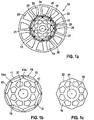
- Fig. 1a-c show by way of example the invention with reference to a designed as a brushless synchronous machine electric machine 10 with three phases and eight poles, twelve grooves 23 in the stator 22 for receiving coil windings, not shown, in which in the rotor 28 within the rotor body 11 to the corresponding eight openings 12 for receiving are provided in the axial direction parallel to the axis of rotation 21 extending permanent magnets.
- the electric machine 10 is designed as an internal rotor, in which the rotor 28 is rotatably mounted within the stator 22 about the axis of rotation 21.
- Fig. 1a shows a plan view of the electric machine 10.
- the parallel to the rotation axis 21 extending grooves 23 are separated by conventional stator teeth 24, the tooth heads are spaced from each other in the usual way in the middle of the grooves 23 each through a small air gap 25.
- an air gap 26 is formed radially.
- the rotor 28 starting from its inner opening 27 for receiving a shaft, not shown, in an inner region 16 on a common radius symmetrically distributed eight material recesses 13 which reduce the mass and the moment of inertia of the rotor 28. Radially spaced from the outer edge 15 toward eight magnetic recordings are arranged with trapezoidal cross-section, which are formed by the openings 12 in the individual slats.
- the core of the rotor 28 forms the inner region 16, radially outside, including the openings 12, the outer region 30 of the rotor 28 is arranged.
- Fig. 1b and 1c show preferred fins 14, 19 of two different types, preferably alternately stacked on each other (lamella 14 - lamella 19 - lamella 14 - lamella 19 - lamella 14 - lamella 19 - etc.) form the rotor body 11 of the rotor 28.
- Fig. 1b is in the radial direction between the openings 12 and the outer edge 15 each have a pole piece 17 in the outer region 30. Between the openings 12 bridges 18 a and webs 18 b are arranged.
- the unwanted short circuit of the magnetic field lines would be observed, which in each case includes the immediate edge areas of two adjacent openings 12, bridges 18a and the narrow webs 18b lying between them.
- the short circuit encloses a few millimeters.
- the arc-shaped on the outer circumference 15 pole pieces 17, the bridges 18a and webs 18b are preferably as narrow as possible and correspond, for example, at the narrowest point about the thickness of the blade 14, while the height in the middle of the pole pieces 17 is significantly greater. The height depends on the geometry, for example, on the number of poles of the electric machine 10.
- the effects of such short circuits are advantageously reduced if alternately a respective lamella 14 of the first type after Fig. 1b and a blade 19 of the second type Fig. 1c are stacked on each other until a desired axial length of the rotor body 11 is reached.
- the lamellae 19 of the second type lie with their dimensions radially within the first type of laminations 14, wherein the lamellae 19 protrudes with its outer edge 20 up to the radially inner edge of the openings 12.
- the fins 19 are formed with their inner region 16 the same as the fins 14, but it lacks the outer region 30th
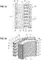
- Fig. 2a shows a section of the electric machine 10 of Fig. 1 as a longitudinal section through the rotor 28 and the stator 22, in which the effect of the proposed preferred alternate arrangement of the fins 14, 19 is clearly visible. Reference numerals for the same elements remain the same in the figures.
- the field lines 34 extend in the section shown perpendicular to the axis of rotation 21 and pass through the permanent magnet 29, the rotor 28 and the stator 22.
- the field lines 34 extend horizontally through the tooth tip 24 of the stator 22 via the air gap 26 between the stator 22 and rotor 28 to the outer region 30th the rotor 28, in which the various slats 14 and 19 are stacked parallel to the axis of rotation 21 alternately.
- the field-focusing regions 32 bundle the field lines 34, while virtually no field lines extend in the field-free regions 31.
- the field-free regions 31 are formed as air gaps and formed by the missing in comparison to the slats 14 fin material of the fins 19 in the outer region 30 of the rotor 28.
- the height of the field-free areas 31 corresponds to the thickness of the fins 19.
- Fig. 2b shows a perspective view of the rotor 28 with formed by openings 12 in its rotor body 11 magnetic recordings.
- the preferred alternating arrangement of the lamellae 14 and 19 can be seen, the pole shoes 17 of the lamellae 14 forming the field-focusing regions 32 and the air gaps between each two spaced by a lamella 19 fins 14, the field-free regions 31 accordingly Fig. 2a ,
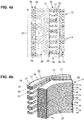
- Fig. 3a-b show an alternative composition of the blades 14 and 19, in which two blades of the first type 14 and two blades of the second type 19 are arranged alternately.
- This design can be used, for example, if lamellae with a maximum thickness of 0.5 mm are used, for example 0.35 mm. With these thinner blades, two blades 14 may be used together to produce a mechanically stable field-focusing portion 32 having a thickness of, for example, 0.7 mm instead of 0.35 mm.
- the proportion of fins 19 to the total number of fins is 50%.
- This composition results in a field-free region 31 with a height of, for example, 0.7 mm, which still generates a sufficient magnetic circuit.
- the height (alternatively referred to as axial extent) of the field-free regions 31 should be as small as possible and should preferably not be greater than 1.3 mm, in particular not greater than 1 mm.
- the reduction of the rotor mass and the rotor inertia and the increase of the air gap flux per pole are in this embodiment largely identical to the design according to Fig. 2a-b be.
- the mechanical time constant and the dynamic properties of the electric machine 10 are also largely identical to the design according to Fig. 2a-b be.
- Fig. 4a-b show a second possible alternative composition of the rotor body 11 of fins 14 and 19, wherein the axial extent of the field-focusing regions 32 is different.
- This design is similar to the design Fig. 3a-b with the exception that the field-focusing regions 32 are formed alternately by one or two fins 14.
- Fig. 4a shows the field lines 34 in a section of the electric machine 10 having this composition.
- Out Fig. 4a It can be seen that this design is able to focus all field lines 34 of the permanent magnet 29.
- the proportion of lamellae of the second type 19 to the total number of lamellae (fins 14 + fins 19) is 57%. This higher proportion leads to a further reduction of the rotor mass, the rotor inertia and the mechanical time constant, which lead to a further improvement of the dynamic properties of the electric machine.
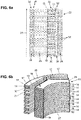
- Fig. 5a-b show a third possible alternative composition of the lamellae 14 and 19, wherein the height or axial extent of the field-free regions 31 is different. This interpretation is similar to that of Fig. 4a-b with the exception that the field-free regions 31 are formed alternately by one or two lamella 19.
- Fig. 5a shows the field lines 34 in a section of the electric machine 10 having this composition. It can be seen from this figure that this design is able to concentrate all field lines 34 from the permanent magnet 29.
- the proportion of fins 19 to the total number of fins (fins 14 + fins 19) is 50% and is identical to the preferred design in FIG Fig.
- Fig. 6a-b show a fourth possible alternative composition of the lamellae 14 and 19.
- This design has a composition in which the total field-free areas 31 make up 40% and the field-focussing areas 32 60% of the total number of louvers (louvers 14 + louvers 19). That is, according to this embodiment, more louvers of the first type 14 are provided as louvers of the second type 19 than in the above-described embodiments:
- the field-free regions 31 are each formed by a lamella 19, while the field-focussing regions 32 are alternately formed by one or two Slats 14 are constructed. This interpretation could eg be advantageous if the stator 22 of the electric machine 10 has a very large armature transverse field and a small air gap 26.
- the field-focusing regions 32 would after Fig. 2 to 5 reach a saturation.
- High saturation of the field-focusing regions 32 should be avoided because this results in a reduction in the difference between the q-axis and the d-axis reactances, which in turn leads to a reduction in the reluctance torque that the electric machine 10 can produce. This fact results in a reduction in the total torque of the electric machine 10 and should therefore be avoided.
- the interpretation after Fig. 6 is with a smaller reduction in rotor mass and rotor inertia compared to the designs below Fig. 2 to 5 connected.
- the axial extent of a field-free region 31 should preferably be a maximum of 1.3 mm, more preferably a maximum of 1 mm, wherein a field-free region 31 may preferably each be formed by one or more lamellae of the second type (eg a 0.5 mm or a 0.65 mm thick slat 19 or two 0.35 mm thick slats 19).
- the field-focusing regions 32 may consist of one or more lamellae of the first type 14.
- the number of fins 14 used will affect the rotor mass, rotor inertia and air gap flux per pole of the electric machine 10, and may be chosen so that the electric machine 10 has the desired dynamic characteristics.
- the number of lamellas with field-free regions is chosen such that their proportion of the total number of lamellae (ie lamellae with field-free regions and lamellae with field-focussing regions) is 30 to 70%.
- Fig. 7a-d show a plan view of a first type of blade 14 for a unillustrated follower pole electric machine with three phases and four poles, and alternative embodiments of fins 19 of the second type ( Fig. 7b, 7c . 7d ).
- the electric machine has six grooves for coil windings and six stator teeth in its stator.
- the preferred rotor 28 has lamellae 14, which in the outer region 30 have two circumferentially opposite elongate openings 12 which form magnet holders for permanent magnets in the stack of the lamellae 14, 19. At its two, the outer circumference 15 facing narrow ends 12a, the openings 12 are tapered. On the outer circumference 12 pole pieces 17 are formed along the openings and pole pieces 17a are formed between the openings 12.
- these fins 19 are rectangular ( Fig. 7b ).
- these fins 19 may be formed at two ends with extensions 20a ( Fig. 7c ), so that the cross section of the fins 19 is greater than in the embodiment in Fig. 7b and the course of the inner region 16 between the two openings 12 with the ends 12a even more closely matched and complementary to the course of the openings 12 is formed with the ends 12a.
- the cross-section of the slats 19 in the region of the pole shoes 17a can be rounded and adapted to the contour of the slats 14 ( Fig. 7d ).
- a portion of the soft magnetic pole pieces 17a is desirably included in the cross section to avoid air gap flux leakage through saturation when a flux density greater than 0.9 Tesla in conventional design (fin package only with fins 14) exists in this region.
- the mechanical time constant (eg, time constant at startup) of the electric machine is also significantly lowered.
- the mechanical time constant is known to be proportional to the moment of inertia of the rotor 28 and inversely proportional to the air gap flux per pole of the electric machine 10. Accordingly, the dynamic properties of the electric machine 10 are improved.
- the electric machine 10 can be modeled by three-dimensional finite element analyzes, which was carried out in the rotor 28 using the example of a three-phase synchronous machine with eight phases, twelve stator teeth and eight magnet mountings for NdFeB permanent magnets.
- a preferred electric machine 10 with an alternative arrangement of louvers 14 and louvers 19 exhibits improved data.
- the values for the preferred electric machine 10 are at a rotor leakage flux of 54%, an air gap flux per pole of 104.5%, a rotor mass of 93.8% and a rotor inertia of 87.7%.
- a dependence of the maximum height in the middle of the arched pole pieces 17 results ( Fig. 1b ) Inversely proportional to the number of poles, for example, falls from about 5 mm at four poles over about 2.5 mm at six poles to just under 2 mm at eight poles.
- the rotor mass M, the rotor inertia T and the mechanical time constant are reduced even more clearly than in the example of the eight-pole electric machine 10. This is in Fig. 8 based on the course of the rotor mass M (2p), the rotor moment of inertia T (2p) and the air gap flux per pole F (2p) as a function of the number of poles 2p shown.
- the four-pole electric machine with the preferred alternating lamination arrangement shows a reduction of the rotor mass M of more than 12% and a reduction of the rotor inertia T of more than 23%.
- the air gap flux F is about 0.2% smaller than with a conventional disk set as a rotor and indicates that suitably a four-pole configuration of the electric machine 10 represents the smallest number of poles for a convenient application of the invention.
Description
- Aus der
WO 03/005531 A1 - Dokument
DE 199 156 64 A1 als nächstliegender Stand der Technik offenbart einen Rotor für eine Elektromaschine, wobei der Rotor Permanentmagnete in v-förmiger Anordnung umfasst, wobei der Rotorkörper an seinem Außenumfang parallel zur Drehachse abwechselnd feldfokussierende und nahezu feldfreie Bereiche ausbildet, die durch eine erste und eine zweite Art von Lamellenblechen gebildet werden. - Gegenstand der Erfindung ist ein Rotor für eine Elektromaschine nach Anspruch 1. Dadurch wird im feldfokussierenden Bereich des Rotors die Flussdichte deutlich erhöht und der durch Kurzschluss in den Brücken verlorene magnetische Fluss vermindert. Als generelle Regel bei der Auslegung solcher Elektromaschinen gilt, dass der magnetische Kreis so ausgelegt wird, dass, wo immer im offenen Kreis möglich, d.h. bei Abwesenheit des Reaktionsfelds der Phasenwicklungen des Stators, eine Flussdichte von etwa 1,6 Tesla erreicht werden soll, damit das Blechpaket, aus dem der Rotor aufgebaut ist, mit zusätzlichem Reaktionsfeld magnetisch voll ausgenutzt werden kann. Ein typischer Stahl, der üblicherweise für die Lamellen verwendet wird, hat eine Sättigungsflussdichte von z.B. 2,1 Tesla. Wird der Rotor konventionell aufgebaut, bildet sich in dem Rotorbereich, in dem sich gemäß der Erfindung die axial alternierend angeordneten feldfokussierenden und feldfreien Bereiche befinden, eine Flussdichte aus, die deutlich geringer ist als diejenige, die mit der alternierenden Anordnung im feldfokussierenden Bereich erreicht werden kann. Dies bedeutet, dass in der konventionellen Anordnung das Lamellenblech hinsichtlich seiner magnetischen Eigenschaften nicht voll ausgenutzt ist. Liegt dieses Gebiet am Rand des Rotors, trägt dieses magnetisch ungenutzte Material nicht nur unvorteilhaft zur Masse des Rotors bei, sondern stellt auch einen bedeutenden Anteil des Trägheitsmoments des Rotors dar, das proportional zur vierten Potenz des Rotorradius ist.
- Die feldfokussierenden Bereiche und die feldfreien Bereiche sind radial zwischen den Permanentmagneten und dem statorseitigen Rotorumfang angeordnet. Als feldfokussierende Bereiche des Rotorkörpers werden Bereiche angesehen, welche gegenüber einem konventionellen Rotorkörper vergrabenen Permanentmagneten eine deutlich erhöhte Flussdichte, z.B. um 70 bis 100%, aufweisen. Die nahezu feldfreien Bereiche werden durch Luftspalte gebildet, bei denen z.B. Material aus den Lamellen entfernt ist und damit die Masse in einem Außenbereich des Rotorkörpers, der üblicherweise die Polschuhe bildet, reduziert wird. Die feldfokussierenden Bereiche hingegen sind durch magnetisch leitfähiges Lamellenblechmaterial, gebildet.
- Der Rotorkörper ist aus Blechlamellen aufgebaut. Erfindungsgemäss ist der Rotorkörper durch wenigstens zwei Arten von vorzugsweise alternierenden Lamellenblechen gebildet, die in Richtung der Drehachse aufeinander gestapelt sind. Damit kann eine einfache Fertigung eines bevorzugten Rotors erfolgen, indem die an sich übliche Lamellenbauweise vorteilhaft ausgenutzt wird, um die vorzugsweise alternierende Anordnung der feldfokussierenden und feldfreien Bereiche auszubilden.
- Erfindungsgemäss liegt die eine Art von Lamellenblechen (nachfolgend auch als zweite Lamellenblechart bezeichnet) mit ihren Abmessungen radial innerhalb der anderen Art von Lamellenblechen (nachfolgend auch als erste Lamellenblechart bezeichnet). Dies ergibt eine sehr einfache Umsetzung der feldfokussierenden und feldfreien Bereiche. Der feldfokussierende Bereich ist durch Lamellenblechmaterial gebildet. Der feldfreie Bereich ist durch einen in axialer Richtung folgenden Luftspalt zwischen zwei Lamellenblechen erster Art gebildet. Zweckmäßige Lamellendicken liegen im Bereich von maximal 1 mm, vorzugsweise von 0,35°mm bis 0,65 mm, z.B. um 0,5 mm. Dickere Lamellen sind generell bei derartigen Elektromaschinen mit im Rotor vergrabenen Permanentmagneten weniger geeignet. Der feldfreie Bereich weist vorzugsweise eine axiale Ausdehnung von maximal 1,3 mm, besonders bevorzugt von maximal 1 mm, auf. Eine größere axiale Ausdehnung ist aufgrund des zu großen Luftspalts nicht von Vorteil. Auch der feldfokussierende Bereich hat bevorzugt eine axiale Ausdehnung von maximal 1,3 mm, besonders bevorzugt von maximal 1 mm. Prinzipiell kann die axiale Ausdehnung des feldfokussierenden Bereiches beliebig gewählt werden. Eine größere axiale Ausdehnung ist jedoch für die vorliegende Erfindung nicht von Vorteil, da die Reduzierung der Rotormassse, und damit der Rotorträgheit, zu gering ausfällt. Durch die bevorzugte Ausgestaltung werden die magnetischen Eigenschaften des Lamellenblechs im feldfokussierenden Bereich deutlich besser ausgenutzt, während das Trägheitsmoment des Rotors durch das fehlende Lamellenmaterial, das als Luftspalt die feldfreien Bereiche bildet, vermindert wird.
- Erfindungsgemäss grenzt das kleinere Lamellenblech, d.h. die zweite Lamellenblechart, mit seinem Außenumfang bei eingesetzten Permanentmagneten an die Permanentmagnete an. Auf diese Weise hat die zweite Lamellenblechart eine geringere radiale Ausdehnung als die erste Lamellenblechart. Die zweite Lamellenblechart hat dabei eine regelmäßige, vorzugsweise rotationssymmetrische, oder unregelmäßige Form. Mit dieser Geometrie lässt sich das Gewicht des Rotors vermindern und die magnetischen Eigenschaften des Rotors optimieren.
- Der Rotorkörper kann auch aus mehr als zwei Arten von Lamellenblechen aufgebaut sein, indem die zweite Lamellenblechart, welche eine geringere radiale Ausdehnung als die erste Lamellenblechart gekennzeichnet ist, durch unterschiedliche Lamellenbleche gebildet wird. Die unterschiedlichen Lamellenbleche der zweiten Lamellenblechart können beispielsweise unterschiedliche radiale Ausdehnungen haben oder unterschiedliche radiale Ausdehnungen in unterschiedlichen Bereichen der Lamellenbleche.
- Bevorzugt ist der Permanentmagnet aus Neodym-Eisen-Bor-haltigem Material (NdFeB) oder Samarium-Cobalt-haltigem Material (SmCo) gebildet.
- Weitere Aspekte der Erfindung ergeben sich aus den abhängigen Ansprüchen, insbesondere wird eine Elektromaschine mit einem Rotor nach Anspruch 1 vorgeschlagen. Vorteilhafterweise ist die Elektromaschine als bürstenlose Synchronmaschine oder einer bürstenlosen Gleichstrommaschine ausgebildet.
- Weitere Ausführungsformen, Aspekte und Vorteile der Erfindung ergeben sich aus nachfolgend anhand von Zeichnungen dargestellten Ausführungsbeispielen der Erfindung. Im Folgenden zeigen:
- Fig. 1 a-c
- a: eine Draufsicht auf eine bevorzugte elektrische Maschine, b: eine Lamelle erster Art, c: eine Lamelle zweiter Art;
- Fig. 2 a-b
- a: Ausschnitt eines Längsschnitts durch eine bevorzugte elektrische Maschine, b: perspektivischer Ausschnitt aus einem bevorzugten Rotor;
- Fig. 3 a-b
- a: Längsausschnitt durch eine elektrische Maschine einer ersten alternativen Ausgestaltung, b: perspektivischer Ausschnitt eines ersten alternativen Rotors;
- Fig. 4 a-b
- a: Längsausschnitt durch eine elektrische Maschine einer zweiten alternativen Ausgestaltung, b: perspektivischer Ausschnitt eines zweiten alternativen Rotors;
- Fig. 5 a-b
- a: Längsausschnitt durch eine elektrische Maschine einer dritten alternativen Ausgestaltung, b: perspektivischer Ausschnitt eines dritten alternativen Rotors;
- Fig. 6 a-b
- a: Längsausschnitt durch eine elektrische Maschine einer vierten alternativen Ausgestaltung, b: perspektivischer Ausschnitt eines vierten alternativen Rotors;
- Fig. 7 a-d
- a: eine Draufsicht auf eine Lamelle erster Art für eine Folgepol-Elektromaschine mit drei Phasen und vier Polen, b: eine erste Ausgestaltung einer Lamelle der zweiten Art, c: eine alternative Ausgestaltung einer Lamelle der zweiten Art und d: eine zweite alternative Ausgestaltung einer Lamelle der zweiten Art; und
- Fig. 8
- das Verhalten von Rotormasse, Rotorträgheitsmoment und Luftspaltfluss in Abhängigkeit von der Polzahl aus einem dreidimensionalen Finite-Element-Modell.
-
Fig. 1a-c zeigen beispielhaft die Erfindung anhand einer als bürstenlose Synchronmaschine ausgebildeten Elektromaschine 10 mit drei Phasen und acht Polen, zwölf Nuten 23 im Stator 22 zur Aufnahme von nicht dargestellten Spulenwicklungen, bei der in dem Rotor 28 innerhalb des Rotorkörpers 11 dem entsprechend acht Öffnungen 12 zur Aufnahme von sich in axialer Richtung parallel zur Drehachse 21 erstreckenden Permanentmagnete vorgesehen sind. Die Elektromaschine 10 ist als Innenläufer ausgebildet, bei der der Rotor 28 innerhalb des Stators 22 um die Drehachse 21 drehbar gelagert ist. -
Fig. 1a zeigt eine Draufsicht auf die Elektromaschine 10. Die sich parallel zur Drehachse 21 erstreckenden Nuten 23 sind durch übliche Statorzähne 24 getrennt, deren Zahnköpfe in üblicher Weise voneinander in der Mitte der Nuten 23 jeweils durch einen kleinen Luftspalt 25 beabstandet sind. Zwischen Stator 22 und Rotor 28 ist radial ein Luftspalt 26 ausgebildet. - Der Rotor 28 weist, ausgehend von seiner inneren Öffnung 27 zur Aufnahme einer nicht dargestellten Welle, in einem Innenbereich 16 auf einem gemeinsamen Radius symmetrisch verteilt acht Materialausnehmungen 13 auf, die die Masse und das Trägheitsmoment des Rotors 28 erniedrigen. Radial beabstandet zum Außenrand 15 hin sind acht Magnetaufnahmen mit trapezförmigem Querschnitt angeordnet, die durch die Öffnungen 12 in den einzelnen Lamellen gebildet sind. Den Kern des Rotors 28 bildet der Innenbereich 16, radial außen einschließlich der Öffnungen 12 ist der Außenbereich 30 des Rotors 28 angeordnet.
- Die
Fig. 1b und 1c zeigen bevorzugte Lamellen 14, 19 zweier verschiedener Arten, die vorzugsweise alternierend aufeinander gestapelt (Lamelle 14 - Lamelle 19 - Lamelle 14 - Lamelle 19 - Lamelle 14 - Lamelle 19 - etc.) den Rotorkörper 11 des Rotors 28 bilden. InFig. 1b ist in radialer Richtung zwischen den Öffnungen 12 und dem Außenrand 15 jeweils ein Polschuh 17 im Außenbereich 30. Zwischen den Öffnungen 12 sind Brücken 18a und Stege 18b angeordnet. In diesem Bereich wäre bei einer konventionellen Ausgestaltung der Elektromaschine 10 der unerwünschte Kurzschluss der Magnetfeldlinien zu beobachten, der jeweils die unmittelbaren Randbereiche zweier benachbarter Öffnungen 12, Brücken 18a und den dazwischen liegenden schmalen Stegen 18b einschließt. Typischerweise umschließt der Kurzschluss wenige Millimeter. Die am Außenumfang 15 bogenförmig ausgebildeten Polschuhe 17, die Brücken 18a und Stege 18b sind vorzugsweise möglichst schmal und entsprechen z.B. an der schmalsten Stelle etwa der Dicke der Lamelle 14, während deren Höhe in der Mitte der Polschuhe 17 deutlich größer ist. Die Höhe hängt geometriebedingt z.B. von der Zahl der Pole der Elektromaschine 10 ab. - Die Auswirkungen solcher Kurzschlüsse werden vorteilhaft verringert, wenn alternierend je eine Lamelle 14 der ersten Art nach
Fig. 1b und eine Lamelle 19 der zweiten Art nachFig. 1c aufeinander gestapelt werden, bis eine gewünschte axiale Länge des Rotorkörpers 11 erreicht ist. Die Lamellen 19 der zweiten Art liegen mit ihren Abmessungen radial innerhalb der ersten Art von Lamellenblechen 14, wobei die Lamellen 19 mit ihrem Außenrand 20 bis an die radial innere Kante der Öffnungen 12 ragt. Die Lamellen 19 sind mit ihrem Innenbereich 16 gleich wie die Lamellen 14 ausgebildet, es fehlt jedoch der Außenbereich 30. -
Fig. 2a zeigt einen Ausschnitt aus der Elektromaschine 10 derFig. 1 als Längsschnitt durch den Rotor 28 und den Stator 22, bei der die Wirkung der vorgeschlagenen bevorzugten alternierenden Anordnung der Lamellen 14, 19 deutlich erkennbar ist. Bezugszeichen für gleiche Elemente bleiben in den Figuren gleich. Die Feldlinien 34 verlaufen im gezeigten Ausschnitt senkrecht zur Drehachse 21 und durchsetzen den Permanentmagneten 29, den Rotor 28 und den Stator 22. Die Feldlinien 34 verlaufen waagrecht durch den Zahnkopf 24 des Stators 22 über den Luftspalt 26 zwischen Stator 22 und Rotor 28 zum Außenbereich 30 des Rotors 28, in dem die verschiedenartigen Lamellen 14 und 19 parallel zur Drehachse 21 alternierend aufeinander gestapelt sind. Die feldfokussierenden Bereiche 32 bündeln die Feldlinien 34, während in den feldfreien Bereichen 31 praktisch keine Feldlinien verlaufen. Die feldfreien Bereiche 31 sind als Luftspalte ausgebildet und entstehen durch das im Vergleich zu den Lamellen 14 fehlende Lamellenmaterial der Lamellen 19 im Außenbereich 30 des Rotors 28. Die Höhe der feldfreien Bereiche 31 entspricht der Dicke der Lamellen 19. Zwischen den Bereichen 31, 32 und der durch die axial übereinander liegenden Öffnungen 12 gebildeten Magnetaufnahme mit dem eingeführten Permanentmagneten 29 ist radial ein kleiner Luftspalt 33 ausgebildet, der z.B. durch Fertigungstoleranzen der Öffnungen 12 bzw. der Permanentmagnete 29 entsteht. Der Permanentmagnet 29 wird homogen von den Feldlinien 34 durchsetzt, die dann in den Innenbereich 16 der Lamellen 19 und 14 eintreten. -
Fig. 2b zeigt eine perspektivische Ansicht des Rotors 28 mit durch Öffnungen 12 in seinem Rotorkörper 11 gebildeten Magnetaufnahmen. Deutlich ist im Außenbereich 30 des Rotors 28 die bevorzugte alternierende Anordnung der Lamellen 14 und 19 zu erkennen, wobei die Polschuhe 17 der Lamellen 14 die feldfokussierenden Bereiche 32 bilden und die Luftspalte zwischen je zwei durch eine Lamelle 19 beabstandete Lamellen 14 die feldfreien Bereiche 31 entsprechendFig. 2a . -
Fig. 3a-b zeigen eine alternative Zusammensetzung der Lamellen 14 und 19, in der zwei Lamellen der ersten Art 14 und zwei Lamellen der zweiten Art 19 alternierend angeordnet sind. Diese Auslegung kann beispielsweise benutzt werden, wenn Lamellen mit einer Dicke von maximal 0,5 mm verwendet werden, z.B. 0,35 mm. Mit diesen dünneren Lamellen können zwei Lamellen 14 zusammen benutzt werden, um einen mechanisch stabilen feldfokussierenden Bereiche 32 zu erzeugen, der eine Dicke von z.B. 0,7 mm statt 0,35 mm hat. Wie in der Ausführungsform nachFigur 2 , beträgt der Anteil von Lamellen 19 zur Gesamtzahl der Lamellen (Lamellen 14 + Lamellen 19) 50%. Diese Zusammensetzung ergibt einen feldfreien Bereich 31 mit einer Höhe von z.B. 0,7 mm, der noch einen ausreichenden Magnetkreis erzeugt. Allgemein gilt, dass die Höhe (alternativ auch als axiale Ausdehnung bezeichnet) der feldfreien Bereiche 31 so klein wie möglich sein sollte und vorzugsweise nicht größer als 1,3 mm, insbesondere nicht größer als 1 mm, sein sollte. Die Reduktion der Rotormasse und der Rotorträgheit und die Erhöhung des Luftspaltflusses pro Pol sind in dieser Ausführungsform weitgehend identisch mit der Auslegung nachFig. 2a-b sein. Die mechanische Zeitkonstante und die Dynamik-Eigenschaften der Elektromaschine 10 werden ebenfalls weitgehend identisch zur Auslegung nachFig. 2a-b sein. -
Fig. 4a-b zeigen eine zweite mögliche alternative Zusammensetzung des Rotorkörpers 11 aus Lamellen 14 und 19, wobei die axiale Ausdehnung der feldfokussierenden Bereiche 32 unterschiedlich ist. Diese Auslegung ist ähnlich der Auslegung nachFig. 3a-b mit der Ausnahme, dass die feldfokussierenden Bereiche 32 abwechselnd durch eine oder zwei Lamellen 14 gebildet ist.Fig. 4a zeigt die Feldlinien 34 in einem Ausschnitt der Elektromaschine 10, die diese Zusammensetzung hat. AusFig. 4a ist ersichtlich, dass diese Auslegung in der Lage ist, alle Feldlinien 34 des Permanentmagneten 29 zu bündeln. Der Anteil von Lamellen der zweiten Art 19 zur Gesamtzahl der Lamellen (Lamellen 14 + Lamellen 19) beträgt dabei 57%. Dieser höhere Anteil führt zu einer weiteren Reduktion der Rotormasse, der Rotorträgheit und der mechanischen Zeitkonstante, die zu einer weiteren Verbesserung der Dynamik-Eigenschaften der Elektromaschine führen. -
Fig. 5a-b zeigen eine dritte mögliche alternative Zusammensetzung der Lamellen 14 und 19, wobei die Höhe bzw. axiale Ausdehnung der feldfreien Bereiche 31 unterschiedlich ist. Diese Auslegung ist ähnlich der derFig. 4a-b mit der Ausnahme, dass die feldfreien Bereiche 31 abwechselnd durch eine oder zwei Lamelle 19 gebildet ist.Fig. 5a zeigt die Feldlinien 34 in einem Ausschnitt der Elektromaschine 10, die diese Zusammensetzung hat. Aus dieser Figur geht hervor, dass diese Auslegung in der Lage ist, alle Feldlinien 34 vom Permanentmagnet 29 zu bündeln. Der Anteil von Lamellen 19 zur Gesamtzahl der Lamellen (Lamellen 14 + Lamellen 19) beträgt 50% und ist identisch mit der bevorzugten Auslegung inFig. 2a-b . Die Reduktion der Rotormasse und der Rotorträgheit und die Erhöhung des Luftspaltflusses pro Pol werden weitgehend identisch zur Auslegung inFig. 2a-b sein. Die mechanische Zeitkonstante und die Dynamik-Eigenschaften der Elektromaschine 10 werden ebenfalls weitgehend identisch zur Auslegung inFig. 2a-b sein. -
Fig. 6a-b zeigen eine vierte mögliche alternative Zusammensetzung der Lamellen 14 und 19. Diese Auslegung hat eine Zusammensetzung, in der insgesamt die feldfreien Bereiche 31 40% und die feldfokussierende Bereiche 32 60% der Gesamtzahl der Lamellen (Lamellen 14 + Lamellen 19) ausmachen. Dies bedeutet, dass gemäß dieser Ausführungsform mehr Lamellen der ersten Art 14 als Lamellen der zweiten Art 19 vorgesehen sind als in den zuvor beschriebenen Ausführungsformen: Die feldfreien Bereiche 31 werden durch jeweils eine Lamelle 19 gebildet, während die feldfokussierenden Bereiche 32 abwechselnd aus einer oder zwei Lamellen 14 aufgebaut sind. Diese Auslegung könnte z.B. vorteilhaft sein, wenn der Stator 22 der Elektromaschine 10 ein sehr großes Ankerquerfeld und einen kleinen Luftspalt 26 aufweist. Unter diesen Bedingungen würden die feldfokussierenden Bereiche 32 nachFig. 2 bis 5 eine Sättigung erreichen. Eine hohe Sättigung der feldfokussierenden Bereiche 32 sollte vermieden werden, weil dies zu einer Reduktion des Unterschieds zwischen der q-Achsen- und der d-Achsen-Reaktanz führt, und dies wiederum zu einer Reduktion des Reluktanzmoments das die Elektromaschine 10 erzeugen kann, führt. Diese Tatsache resultiert in einer Reduktion des gesamten Drehmomentes der Elektromaschine 10 und sollte deshalb vermieden werden. Die Auslegung nachFig. 6 ist mit einer kleineren Verringerung der Rotormasse und der Rotorträgheit im Vergleich zu den Auslegungen nachFig. 2 bis 5 verbunden. - Weitere Ausgestaltungen des Rotorkörpers mit Lamellen der ersten und der zweiten Art sind denkbar, um Eigenschaften zu erreichen, die ähnlich sind zur bevorzugten Auslegung in
Fig. 2a-b . Die axiale Ausdehnung eines feldfreien Bereiches 31 sollte vorzugsweise maximal 1,3 mm, besonders bevorzugt maximal 1 mm, sein, wobei ein feldfreier Bereich 31 bevorzugt jeweils durch eine oder mehrere Lamellen der zweiten Art gebildet sein kann (z.B. eine 0,5 mm oder eine 0,65 mm dicke Lamelle 19 oder zwei 0,35 mm dicke Lamellen 19). Die feldfokussierenden Bereiche 32 können aus einer oder mehreren Lamellen der ersten Art 14 bestehen. Die Anzahl von verwendeten Lamellen 14 werden die Rotormasse, die Rotorträgheit und den Luftspaltfluss pro Pol der Elektromaschine 10 beeinflussen und kann so gewählt werden, dass die Elektromaschine 10 die gewünschten Dynamik-Eigenschaften aufweist. Insbesondere wird die Anzahl der Lamellen mit feldfreien Bereichen (Lamellen der zweiten Art) so gewählt, dass ihr Anteil an der Gesamtanzahl der Lamellen (d.h. Lamellen mit feldfreien Bereichen und Lamellen mit feldfokussierenden Bereichen) 30 bis 70 % beträgt. - Die
Fig. 7a-d zeigen eine Draufsicht auf eine erste Art Lamelle 14 für eine nicht dargestellte Folgepol-Elektromaschine mit drei Phasen und vier Polen, sowie alternative Ausgestaltungen von Lamellen 19 der zweiten Art (Fig. 7b, 7c ,7d ). - Die Elektromaschine weist in ihrem Stator sechs Nuten für Spulenwicklungen sowie sechs Statorzähne auf. Der bevorzugte Rotor 28 weist Lamellen 14 auf, die im Außenbereich 30 zwei umfänglich gegenüberliegende längliche Öffnungen 12 aufweisen, die im Stapel der Lamellen 14, 19 Magnetaufnahmen für Permanentmagnete bilden. An ihren beiden, dem Außenumfang 15 zugewandten schmalen Enden 12a sind die Öffnungen 12 zugespitzt. Am Außenumfang sind entlang der Öffnungen 12 Polschuhe 17 und zwischen den Öffnungen 12 Polschuhe 17a ausgebildet.
- Weiterhin weist der Rotor 28 Lamellen 19 auf, die gleich dem Innenbereich 16 des Rotors 28 ausgebildet sind. In einer ersten bevorzugten Ausgestaltung sind diese Lamellen 19 rechteckig ausgebildet (
Fig. 7b ). Alternativ können diese Lamellen 19 an zwei Enden mit Erweiterungen 20a ausgebildet sein (Fig. 7c ), so dass der Querschnitt der Lamellen 19 größer ist als im Ausführungsbeispiel inFig. 7b und dem Verlauf des Innenbereichs 16 zwischen den beiden Öffnungen 12 mit den Enden 12a noch enger angepasst und komplementär zum Verlauf der Öffnungen 12 mit den Enden 12a ausgebildet ist. Ebenso kann der Querschnitt der Lamellen 19 im Bereich der Polschuhe 17a gerundet und an die Kontur der Lamellen 14 angepasst sein (Fig. 7d ). Bei diesen Alternativen ist günstigerweise ein Teil der weichmagnetischen Polschuhe 17a in den Querschnitt eingeschlossen, um Luftspaltflussverluste durch Sättigung zu vermeiden, wenn eine Flussdichte von mehr als 0,9 Tesla in konventioneller Auslegung (Lamellenpaket nur mit Lamellen 14) in diesem Bereich existiert. - Durch die bevorzgute alternierende Anordnung der Lamellen 14 und 19 entfallen 50% der Polschuhe 17, 17a im Rotor 28, wie z.B.
Fig. 2b zeigt. Damit entfällt auch der - in der konventionellen Ausgestaltung der Lamellen - verlorene kurzgeschlossene magnetische Streufluss zu etwa 50%. Die Verminderung des Streuflusses erhöht damit den magnetischen Fluss im Luftspalt 26 (Fig. 1a ,Fig. 2a ), wodurch sich das Moment durch magnetische Ausrichtung der Elektromaschine 10 erhöht. Weiterhin ist auch, durch die kleinere Fläche der Lamellen 19, die Masse und das Trägheitsmoment des Rotors 28 bzw. der Elektromaschine 10 reduziert. Durch die Verminderung des Rotorträgheitsmoments und dem Anstieg des Luftspaltflusses wird auch die mechanische Zeitkonstante (z.B. Zeitkonstante beim Start) der Elektromaschine signifikant erniedrigt. Die mechanische Zeitkonstante ist bekanntermaßen proportional zum Trägheitsmoment des Rotors 28 und umgekehrt proportional zum Luftspaltfluss pro Pol der Elektromaschine 10. Entsprechend werden auch die dynamischen Eigenschaften der Elektromaschine 10 verbessert. - Durch dreidimensionale Finite-Element-Analysen kann die Elektromaschine 10 modelliert werden, was am Beispiel einer als achtpoliger Innenläufer ausgebildeten Synchronmaschine mit drei Phasen, zwölf Statorzähnen und acht Magnetaufnahmen für NdFeB-Permanentmagnete im Rotor 28 durchgeführt wurde.
- Verglichen mit einer konventionellen Maschine, deren Rotor mit einem Blechpaket aus gleichartigen Lamellen 14 ausgebildet ist, zeigt eine bevorzugte Elektromaschine 10 mit einer alternativen Anordnung von Lamellen 14 und Lamellen 19 verbesserte Daten.
- Weist die konventionelle Maschine einen Rotorstreufluss von 100%, einen Luftspaltfluss pro Pol von 100%, eine Rotormasse von 100% und ein Rotorträgheitsmoment von 100% auf, liegen die Werte für die bevorzugte Elektromaschine 10 bei einem Rotorstreufluss von 54%, einem Luftspaltfluss pro Pol von 104,5%, einer Rotormasse von 93,8% und einem Rotorträgheitsmoment von 87,7%.
- Werden vergleichbare Elektromaschinen 10 mit vier, sechs oder acht Polen betrachtet, ergibt sich eine Abhängigkeit der maximalen Höhe in der Mitte der gewölbten Polschuhe 17 (
Fig. 1b ) umgekehrt proportional zur Anzahl der Pole, die z.B. von etwa 5 mm bei vier Polen über etwa 2,5 mm bei sechs Polen auf knapp 2 mm bei acht Polen fällt. Bei Rotoren 28 für vierpolige oder sechspolige Elektromaschinen 10 werden die Rotormasse M, das Rotorträgheitsmoment T und die mechanische Zeitkonstante noch deutlicher reduziert als beim Beispiel der achtpoligen Elektromaschine 10. Dies ist inFig. 8 anhand des Verlaufs der Rotormasse M(2p), des Rotorträgheitsmoments T(2p) und des Luftspaltflusses pro Pol F(2p) in Abhängigkeit von der Polzahl 2p dargestellt. - Die vierpolige Elektromaschine mit der bevorzugten alternierenden Lamellenanordnung zeigt eine Reduktion der Rotormasse M von mehr als 12% und eine Reduktion des Rotorträgheitsmoments T von mehr als 23%. Der Luftspaltfluss F ist mit etwa 0,2% kleiner als mit einem konventionellen Lamellenpaket als Rotor und deutet an, dass zweckmäßigerweise eine vierpolige Ausgestaltung der Elektromaschine 10 die kleinste Polzahl für eine zweckmäßige Anwendung der Erfindung darstellt.
Claims (5)
- Rotor (28) für eine Elektromaschine, wobei der Rotor (28) um eine Drehachse (21) drehbar gelagert ist und wobei der Rotor (28) einen Rotorkörper (11) und Permanentmagnete (29) umfasst, wobei der Rotorkörper (11) parallel zur Drehachse (21) abwechselnd feldfokussierende und nahezu feldfreie Bereiche (32, 31) ausbildet, wobei die nahezu feldfreien Bereiche durch Luftspalte gebildet sind und wobei der Rotorkörper (11) durch wenigstens zwei Arten von Lamellenblechen (14, 19) gebildet ist, die in Richtung der Drehachse (21) aufeinander gestapelt sind, und die zweite Art von Lamellenblechen (19) mit ihren Abmessungen radial innerhalb der ersten Art von Lamellenblechen (14) liegen, wobei die Lamellenbleche der zweiten Art (19) mit ihrem jeweiligen Außenumfang (20) bei eingesetzten Permanentmagneten (29) an die Permanentmagnete (29) angrenzen, wobei die Permanentmagnete radial magnetisiert sind und sich in tangentialer Richtung erstrecken, wobei die die feldfreien Bereiche (31) bildenden Luftspalte in axialer Richtung zwischen zwei Lamellenblechen erster Art (14) ausgebildet sind, wobei die feldfokussierenden Bereiche (32) radial zwischen den Permanentmagneten (29) und dem statorseitigen Rotorumfang (15) angeordnet sind und wobei in dem Rotor (28) innerhalb des Rotorkörpers (11) Öffnungen (12) zur Aufnahme von den sich in axialer Richtung parallel zur Drehachse (21) erstreckenden Permanentmagneten vorgesehen sind und der Rotor als Innenläufer ausgebildet ist
- Rotor (28) nach Anspruch 1, dadurch gekennzeichnet, dass die feldfokussierenden Bereiche (32) durch Lamellenblechmaterial gebildet sind.
- Rotor (28) nach einem der vorhergehenden Ansprüche, dadurch gekennzeichnet, dass die Öffnungen (12) einen trapezförmigen Querschnitt aufweisen.
- Elektromaschine mit einem Rotor (28) nach einem der vorhergehenden Ansprüche.
- Elektromaschine nach Anspruch 4, dadurch gekennzeichnet, dass die Elektromaschine als bürstenlose Synchronmaschine oder bürstenlose Gleichstrommaschine ausgebildet ist.
Applications Claiming Priority (3)
| Application Number | Priority Date | Filing Date | Title |
|---|---|---|---|
| DE102005055342 | 2005-11-21 | ||
| DE102006006882A DE102006006882A1 (de) | 2005-11-21 | 2006-02-15 | Elektromaschine und Rotor für eine Elektromaschine |
| PCT/EP2006/068497 WO2007057412A1 (de) | 2005-11-21 | 2006-11-15 | Anordnung von rotorblechen einer permanenterregten elektrischen maschine |
Publications (2)
| Publication Number | Publication Date |
|---|---|
| EP1955426A1 EP1955426A1 (de) | 2008-08-13 |
| EP1955426B1 true EP1955426B1 (de) | 2019-10-02 |
Family
ID=37728430
Family Applications (1)
| Application Number | Title | Priority Date | Filing Date |
|---|---|---|---|
| EP06819508.0A Expired - Fee Related EP1955426B1 (de) | 2005-11-21 | 2006-11-15 | Elektromaschine und rotor für eine elektromaschine |
Country Status (7)
| Country | Link |
|---|---|
| US (1) | US20080296990A1 (de) |
| EP (1) | EP1955426B1 (de) |
| JP (1) | JP5101516B2 (de) |
| KR (1) | KR101018990B1 (de) |
| CN (1) | CN101313450B (de) |
| DE (1) | DE102006006882A1 (de) |
| WO (1) | WO2007057412A1 (de) |
Families Citing this family (16)
| Publication number | Priority date | Publication date | Assignee | Title |
|---|---|---|---|---|
| DE102008032844A1 (de) | 2008-07-14 | 2010-01-21 | Hanning Elektro-Werke Gmbh & Co. Kg | Permanentmagnetischer Rotor |
| DE102010029251A1 (de) * | 2010-05-25 | 2011-12-01 | Robert Bosch Gmbh | Komponente für eine elektriche Maschine sowie Verfahren und Blechlamelle zum Aufbau einer solchen Komponente |
| JP2012023876A (ja) * | 2010-07-15 | 2012-02-02 | Hitachi Appliances Inc | 永久磁石式回転電機 |
| RU2568300C2 (ru) * | 2010-09-17 | 2015-11-20 | Хеганес Аб (Пабл) | Ротор для электрической машины с модуляцией полюсов |
| JP2012095401A (ja) * | 2010-10-25 | 2012-05-17 | Yaskawa Electric Corp | 回転電機の回転子及び回転電機 |
| JP5244895B2 (ja) * | 2010-12-02 | 2013-07-24 | 山洋電気株式会社 | 発電機用コア |
| US9729032B2 (en) | 2013-06-17 | 2017-08-08 | Tesla, Inc. | Limiting radial expansion in rotor balancing |
| US9496775B2 (en) | 2013-06-19 | 2016-11-15 | Tesla Motors, Inc. | Controlling end ring balance in pre-balancing spinning process |
| WO2015059768A1 (ja) * | 2013-10-22 | 2015-04-30 | 三菱電機株式会社 | 回転電機用ロータ |
| JP2015162980A (ja) * | 2014-02-27 | 2015-09-07 | 株式会社豊田自動織機 | 回転電機の永久磁石埋設型回転子、及び回転電機 |
| JP6337549B2 (ja) * | 2014-03-20 | 2018-06-06 | 株式会社ジェイテクト | 磁石埋込型ロータ |
| US9800107B2 (en) * | 2014-10-20 | 2017-10-24 | Hyundai Mobis Co., Ltd. | Rotor |
| JP6382085B2 (ja) * | 2014-11-28 | 2018-08-29 | 日立オートモティブシステムズ株式会社 | 回転電機の回転子及びそれを用いた回転電機 |
| US9780606B2 (en) * | 2015-02-18 | 2017-10-03 | GM Global Technology Operations LLC | Multi material rotor core |
| JP6308177B2 (ja) * | 2015-06-26 | 2018-04-11 | 株式会社デンソー | 回転子 |
| JP7348086B2 (ja) | 2020-01-14 | 2023-09-20 | 日立Astemo株式会社 | 回転電機、及び車載電動機システム |
Family Cites Families (18)
| Publication number | Priority date | Publication date | Assignee | Title |
|---|---|---|---|---|
| GB2248348B (en) * | 1990-09-28 | 1994-04-27 | Johnson Electric Sa | A brush holder for an electric motor |
| CA2135817C (en) * | 1993-11-19 | 1998-08-11 | Hirobumi Satomi | Combined linear-rotary stepping motor |
| US5753991A (en) * | 1994-12-02 | 1998-05-19 | Hydro-Quebec | Multiphase brushless AC electric machine |
| DE69636505T2 (de) * | 1995-06-07 | 2007-05-24 | General Electric Co. | Dynamoelektrische Maschine und deren Rotorkonstruktion |
| SE511896C2 (sv) * | 1996-12-04 | 1999-12-13 | Vilmos Toeroek | Elektrisk rotationsmotor med utpräglade poler |
| DE69833081T2 (de) * | 1997-10-13 | 2006-08-31 | Matsushita Electric Industrial Co., Ltd., Kadoma | Motor mit innerem Permanentmagnetrotor |
| DE19915664A1 (de) * | 1999-04-07 | 2000-10-19 | Siemens Ag | Elektrische Maschine mit einem Stator |
| JP2001157396A (ja) * | 1999-11-29 | 2001-06-08 | Mitsubishi Electric Corp | 回転電機の回転子及び回転子コアの製造方法 |
| JP2002044887A (ja) * | 2000-07-19 | 2002-02-08 | Nippon Densan Corp | モータ用ロータ |
| DE10056036A1 (de) * | 2000-11-11 | 2002-05-29 | Bosch Gmbh Robert | Anker |
| JP3856661B2 (ja) * | 2001-06-06 | 2006-12-13 | 株式会社荏原製作所 | 真空ポンプ |
| DE10131474A1 (de) * | 2001-06-29 | 2003-05-28 | Bosch Gmbh Robert | Elektrische Maschine |
| SE0201298D0 (sv) * | 2002-04-30 | 2002-04-30 | Vilmos Toeroek | High-speed synchronous motor |
| JP4043281B2 (ja) * | 2002-05-15 | 2008-02-06 | 三洋電機株式会社 | インナーロータ形モータのロータ装置 |
| US7034422B2 (en) * | 2002-05-24 | 2006-04-25 | Virginia Tech Intellectual Properties, Inc. | Radial-axial electromagnetic flux electric motor, coaxial electromagnetic flux electric motor, and rotor for same |
| US7057323B2 (en) * | 2003-03-27 | 2006-06-06 | Emerson Electric Co. | Modular flux controllable permanent magnet dynamoelectric machine |
| US20040201301A1 (en) * | 2003-04-11 | 2004-10-14 | Regan Christopher Daniel | Simple rotor assembly for a reluctance machine |
| US20040251763A1 (en) * | 2003-06-13 | 2004-12-16 | Matsushita Electric Industrial Co., Ltd. | Motor |
-
2006
- 2006-02-15 DE DE102006006882A patent/DE102006006882A1/de not_active Withdrawn
- 2006-11-15 KR KR1020087012143A patent/KR101018990B1/ko active IP Right Grant
- 2006-11-15 US US12/094,560 patent/US20080296990A1/en not_active Abandoned
- 2006-11-15 CN CN2006800432672A patent/CN101313450B/zh not_active Expired - Fee Related
- 2006-11-15 EP EP06819508.0A patent/EP1955426B1/de not_active Expired - Fee Related
- 2006-11-15 WO PCT/EP2006/068497 patent/WO2007057412A1/de active Application Filing
- 2006-11-15 JP JP2008541705A patent/JP5101516B2/ja not_active Expired - Fee Related
Non-Patent Citations (1)
| Title |
|---|
| None * |
Also Published As
| Publication number | Publication date |
|---|---|
| KR20080077128A (ko) | 2008-08-21 |
| JP2009516997A (ja) | 2009-04-23 |
| DE102006006882A1 (de) | 2007-05-24 |
| CN101313450B (zh) | 2012-06-20 |
| JP5101516B2 (ja) | 2012-12-19 |
| KR101018990B1 (ko) | 2011-03-07 |
| WO2007057412A1 (de) | 2007-05-24 |
| CN101313450A (zh) | 2008-11-26 |
| EP1955426A1 (de) | 2008-08-13 |
| US20080296990A1 (en) | 2008-12-04 |
Similar Documents
| Publication | Publication Date | Title |
|---|---|---|
| EP1955426B1 (de) | Elektromaschine und rotor für eine elektromaschine | |
| EP2951909B1 (de) | Rotor, reluktanzmaschine und herstellungsverfahren für den rotor | |
| DE69833081T2 (de) | Motor mit innerem Permanentmagnetrotor | |
| DE112006002546B4 (de) | Elektromotor mit asymmetrischen Polen | |
| EP0762619A2 (de) | Verfahren und Vorrichtung zur Reduzierung des sogenannten Nutruckens bei einem Elektromotor | |
| EP1620932A1 (de) | Elektrische maschine | |
| DE112015001725T5 (de) | Drehende elektrische Maschine mit eingebetteten Permanentmagneten | |
| DE102009054069A1 (de) | Dreiphasige dynamoelektrische permanenterregte Synchronmaschine | |
| DE102008056934A1 (de) | Maschine mit konzentrierten Wicklungen mit magnetischen Schlitzkeilen | |
| DE112008001226T5 (de) | Rotor einer rotierenden elektrischen Maschine und Fertigungsverfahren dafür | |
| WO2007141230A1 (de) | Wechselstromgenerator für kraftfahrzeuge | |
| DE102012212775A1 (de) | Rotoranordnung für eine elektrische Maschine | |
| EP3545610A1 (de) | Synchron-maschine mit magnetischer drehfelduntersetzung und flusskonzentration | |
| DE102011080671A1 (de) | Rotor für eine permanentmagnetische Maschine | |
| DE102010038486A1 (de) | Wicklungen mit eckigem Querschnitt für Rotoren von elektrischen Maschinen | |
| EP2601726A2 (de) | Wicklungszahn und komponente für eine elektrische maschine zur reduzierung von wirbelströmen | |
| EP2479872B1 (de) | Permanenterregte synchronmaschine mit einem rotor | |
| WO2011131582A2 (de) | Statoranordnung für eine permanentmagneterregte elektrische maschine | |
| DE102016212022A1 (de) | Rotor | |
| EP3830930B1 (de) | Elektrische maschine | |
| DE102010062981A1 (de) | Maschinenkomponente für eine elektrische Maschine | |
| EP2577846B1 (de) | Permanentmagnetrotor für eine elektrische maschine sowie herstellungsverfahren und blechlamelle eines solchen rotors | |
| DE102012218995A1 (de) | Läuferanordnung für eine permanentmagneterregte elektrische Maschine | |
| EP3252923B1 (de) | Zwei-phasen elektromotor | |
| DE102014212807A1 (de) | Verfahren zur Herstellung eines Rotors für einen permanenterregten Synchronmotor |
Legal Events
| Date | Code | Title | Description |
|---|---|---|---|
| PUAI | Public reference made under article 153(3) epc to a published international application that has entered the european phase |
Free format text: ORIGINAL CODE: 0009012 |
|
| 17P | Request for examination filed |
Effective date: 20080623 |
|
| AK | Designated contracting states |
Kind code of ref document: A1 Designated state(s): DE FR HU IT |
|
| DAX | Request for extension of the european patent (deleted) | ||
| RBV | Designated contracting states (corrected) |
Designated state(s): DE FR HU IT |
|
| 17Q | First examination report despatched |
Effective date: 20100614 |
|
| GRAP | Despatch of communication of intention to grant a patent |
Free format text: ORIGINAL CODE: EPIDOSNIGR1 |
|
| STAA | Information on the status of an ep patent application or granted ep patent |
Free format text: STATUS: GRANT OF PATENT IS INTENDED |
|
| INTG | Intention to grant announced |
Effective date: 20190527 |
|
| GRAS | Grant fee paid |
Free format text: ORIGINAL CODE: EPIDOSNIGR3 |
|
| GRAA | (expected) grant |
Free format text: ORIGINAL CODE: 0009210 |
|
| STAA | Information on the status of an ep patent application or granted ep patent |
Free format text: STATUS: THE PATENT HAS BEEN GRANTED |
|
| AK | Designated contracting states |
Kind code of ref document: B1 Designated state(s): DE FR HU IT |
|
| REG | Reference to a national code |
Ref country code: DE Ref legal event code: R096 Ref document number: 502006016346 Country of ref document: DE |
|
| PGFP | Annual fee paid to national office [announced via postgrant information from national office to epo] |
Ref country code: FR Payment date: 20191128 Year of fee payment: 14 |
|
| RAP2 | Party data changed (patent owner data changed or rights of a patent transferred) |
Owner name: ROBERT BOSCH GMBH |
|
| REG | Reference to a national code |
Ref country code: DE Ref legal event code: R097 Ref document number: 502006016346 Country of ref document: DE |
|
| REG | Reference to a national code |
Ref country code: DE Ref legal event code: R084 Ref document number: 502006016346 Country of ref document: DE |
|
| PLBE | No opposition filed within time limit |
Free format text: ORIGINAL CODE: 0009261 |
|
| STAA | Information on the status of an ep patent application or granted ep patent |
Free format text: STATUS: NO OPPOSITION FILED WITHIN TIME LIMIT |
|
| PG25 | Lapsed in a contracting state [announced via postgrant information from national office to epo] |
Ref country code: IT Free format text: LAPSE BECAUSE OF FAILURE TO SUBMIT A TRANSLATION OF THE DESCRIPTION OR TO PAY THE FEE WITHIN THE PRESCRIBED TIME-LIMIT Effective date: 20191002 |
|
| 26N | No opposition filed |
Effective date: 20200703 |
|
| PG25 | Lapsed in a contracting state [announced via postgrant information from national office to epo] |
Ref country code: HU Free format text: LAPSE BECAUSE OF FAILURE TO SUBMIT A TRANSLATION OF THE DESCRIPTION OR TO PAY THE FEE WITHIN THE PRESCRIBED TIME-LIMIT; INVALID AB INITIO Effective date: 20061115 |
|
| PG25 | Lapsed in a contracting state [announced via postgrant information from national office to epo] |
Ref country code: FR Free format text: LAPSE BECAUSE OF NON-PAYMENT OF DUE FEES Effective date: 20201130 |
|
| PGFP | Annual fee paid to national office [announced via postgrant information from national office to epo] |
Ref country code: DE Payment date: 20220125 Year of fee payment: 16 |
|
| REG | Reference to a national code |
Ref country code: DE Ref legal event code: R119 Ref document number: 502006016346 Country of ref document: DE |
|
| PG25 | Lapsed in a contracting state [announced via postgrant information from national office to epo] |
Ref country code: DE Free format text: LAPSE BECAUSE OF NON-PAYMENT OF DUE FEES Effective date: 20230601 |