EP1953893A2 - Zentralisierte Notbeleuchtungsanlage mit in die normale Beleuchtung integrierten Funktionen - Google Patents
Zentralisierte Notbeleuchtungsanlage mit in die normale Beleuchtung integrierten Funktionen Download PDFInfo
- Publication number
- EP1953893A2 EP1953893A2 EP08425046A EP08425046A EP1953893A2 EP 1953893 A2 EP1953893 A2 EP 1953893A2 EP 08425046 A EP08425046 A EP 08425046A EP 08425046 A EP08425046 A EP 08425046A EP 1953893 A2 EP1953893 A2 EP 1953893A2
- Authority
- EP
- European Patent Office
- Prior art keywords
- emergency
- lighting
- lighting apparatus
- electric
- supply
- Prior art date
- Legal status (The legal status is an assumption and is not a legal conclusion. Google has not performed a legal analysis and makes no representation as to the accuracy of the status listed.)
- Withdrawn
Links
Images

Classifications
-
- H—ELECTRICITY
- H02—GENERATION; CONVERSION OR DISTRIBUTION OF ELECTRIC POWER
- H02J—CIRCUIT ARRANGEMENTS OR SYSTEMS FOR SUPPLYING OR DISTRIBUTING ELECTRIC POWER; SYSTEMS FOR STORING ELECTRIC ENERGY
- H02J9/00—Circuit arrangements for emergency or stand-by power supply, e.g. for emergency lighting
- H02J9/02—Circuit arrangements for emergency or stand-by power supply, e.g. for emergency lighting in which an auxiliary distribution system and its associated lamps are brought into service
-
- H—ELECTRICITY
- H05—ELECTRIC TECHNIQUES NOT OTHERWISE PROVIDED FOR
- H05B—ELECTRIC HEATING; ELECTRIC LIGHT SOURCES NOT OTHERWISE PROVIDED FOR; CIRCUIT ARRANGEMENTS FOR ELECTRIC LIGHT SOURCES, IN GENERAL
- H05B47/00—Circuit arrangements for operating light sources in general, i.e. where the type of light source is not relevant
- H05B47/10—Controlling the light source
- H05B47/175—Controlling the light source by remote control
- H05B47/19—Controlling the light source by remote control via wireless transmission
Definitions
- the present invention relates to a centralized emergency lighting plant with functionalities integrated with ordinary lighting.
- the invention concerns an emergency lighting system, of the centralized battery type, which allows the complete integration of the emergency lighting function, so that the same ordinary lighting apparatus are also emergency lighting apparatus and can be configured and programmed in their functionalities by a control station.
- a centralized emergency or safety lighting plant consists of one or more electrical energy sources, which supply the lighting apparatus located in the periphery.
- the energy source and the lighting apparatus are connected by a series of safety circuits, installed with particular shrewdness of reliability for the proper functioning of the emergency lighting.
- a static supply group which draws the energy from storage batteries, with output in DC or AC, or a generating set is used to supply centralized safety lighting plants.
- UPS uninterruptible power supply
- generating set in which the uninterruptible power supply feeds the emergency plant for the time necessary for the generating set to start and to become operative.
- the supplier in permanent DC is used when it is necessary to feed, without an interruption, a load at the charge voltage of the battery (relays, contactors, motors, etc.); the load is supplied by a rectifier bridge directly from the network and, when there is no voltage on the network, the load is supplied by the battery without the slightest supply interruption (null intervention time).
- the load In case of permanent AC supply, in presence of voltage, the load is directly fed from the network and, simultaneously, a battery charger provides for the battery recharging; in absence of network voltage, the load is switched on the inverter, which converts the battery voltage in an alternating voltage at low distortion, by means of a contactor.
- an aim of the present invention is to realize a centralized emergency lighting plant with functionalities integrated with ordinary lighting, which allows to consider the same ordinary lighting apparatus also emergency lighting apparatus, since each lighting apparatus can be on or off in case of emergency and automatically recognizes the emergency condition by the electric state (DC or special AC) of the line to which said lighting apparatus is connected.
- Another aim of the present invention is to realize a centralized emergency lighting plant with functionalities integrated with ordinary lighting, which permits to schedule the emergency operation of any lighting apparatus of the plant, which, then, can be switched on in case of emergency with any desired light intensity and configured by a control station and for any predetermined emergency time, consistent with the energy available in the centralized batteries.
- a further aim of the present invention is to realize a centralized emergency lighting plant with functionalities integrated with ordinary lighting, which allows to implement its functionalities in the existing plants, without changing the most onerous part of the installation part, namely the electric supply lines of the pre-existing lighting apparatus, but only by acting on the electric supply boards, with a significant competitive advantage in terms of installation easiness and quickness and of outstanding reduction of the installation and operating costs.
- all the lighting apparatus are connected on the same electric line, both those which are switched on in case of emergency and those which are switched off in case of emergency and every lighting apparatus is provided with an electronic supplier (ballast) for controlling the fluorescent lamps with which said lighting apparatus is equipped.
- Each electronic supplier for controlling fluorescent lamps is also equipped with a built-in two-way radio and can be controlled and reconfigured by radio; it is possible to configure by radio all the operating characteristics of the supplier and, in particular, its mode of operation when it is active for the ordinary lighting (autodimmer, fixed power), its mode of operation in case of emergency (dimmer level, lighting state in case of emergency) and the values of all the operational parameters.
- each electronic supplier for controlling fluorescent lamps is able to decode some parameters of its power supply (amplitude, frequency, phase) in the early moments of the supply presence on its input, to determine its operation state (switching on in the state of ordinary lighting or switching on in the state of emergency lighting or switching off).
- the same devices are connected to each supply cable of the lighting apparatus, which, by changing their way of functioning on the basis of the manner of dispensing the electric energy, will switch on, alternately, in ordinary modality or in emergency modality.
- the attached figure 1 shows the electrical connections necessary to the insertion of the emergency function in a typical industrial electric board 24, which supplies a lighting section.
- the portion 23 of the emergency cabinet 10 contains the electronic devices necessary to provide the electric energy for the operation of the emergency lighting apparatus, such as the battery charger of the centralised batteries 13, the measurement instruments of the presence of the network supply (230 Volt in AC) on the controlled lines (LSSA INPUT and line 38), the central electronic unit (CPU) for the management of the operation logic and the system diagnostics, the power card of output, each of which provides the supply power to a certain group of lighting apparatus 11 (PWR OUT outputs 1, 2 and the respective electric lines 20, 21) and is able to control at least a remote control switch 12 (with the output CMD 1, CMD 2 and the respective electric lines 39, 40).
- the electronic devices necessary to provide the electric energy for the operation of the emergency lighting apparatus such as the battery charger of the centralised batteries 13, the measurement instruments of the presence of the network supply (230 Volt in AC) on the controlled lines (LSSA INPUT and
- a remote control switch 12 for every separate electric supply line 16, 19 of each series of the lighting apparatus 11 must be added to the existing plant.
- the remote control switches 12 are connected in such a way as to, in the rest position (shown in figure 1 ), the lighting apparatus 11 are supplied by the ordinary electric supply line 17 through the existing switches 18 and the three-phase disconnecting switch 34 of the lighting subsection to which they belong.
- the remote control switches 12 are automatically energized and the emergency electric power generated by the cabinet 10 is provided to the electric lines 19 through the emergency electric lines 20, 21.
- the lighting apparatus 11 connected to the electric lines 12 automatically recognize to be supplied by an emergency source (in DC or in AC with certain values of amplitude, frequency and/or phase) and regulate their operation accordingly, so as to:
- the cabinet 10 continuously monitors the supply line 22 downstream the three-phase disconnecting switch 34 to start up the emergency function in the event of lack of supply and, when the supply network lacks or the three-phase disconnecting switch 34 manually opens, the emergency cabinet 10 reveals the lack of supply and activates the emergency function.
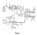
- FIG. 2 which illustrates the integrated lighting system as a whole, shows that the plant, in general, provides for an emergency supply cabinet 10 for each electric board 24, which contains a supply subsection 25 (which picks up the electric energy from the ordinary supply network 26) of the electric lines 19 of the lighting apparatus 11.
- each emergency cabinet 10 The electronic processing and control unit (CPU) located inside each emergency cabinet 10 is provided with a FH DSSS two-way radio, which allows the communication with the other cabinet 10 of the system and with a control station 27, which communicates with each lighting apparatus 11, by means of two-way radio 33 integrated in their respective electronic supplier 31 controlling each fluorescent lamp 32 of every lighting apparatus 11.
- CPU central processing and control unit
- the control station 27 is single in the system and performs the following functions:
- control station 27 along with its built-in GSM modem 43, represents the interface for the remote control of the system, through the GSM network 28.
- Each lighting apparatus 11 used in emergency performs the test of the emergency function every time the cabinet 10 starts up such a function.
- Every cabinet periodically and according to a calendar scheduled in the system, performs operation tests and autonomy tests supplying its emergency electric lines 19, at prefixed hours and for prearranged times.
- every connected apparatus 11, for which the emergency function is active records in its memory its diagnostics information to make them available to the control station 27 of the system.
- control station 27 in coordination with the electronic control units (CPU) of the various cabinets 10, through the radio network R, is able to question each lighting apparatus 11 used in emergency, collecting the results of the emergency operation tests performed by the individual apparatus 11, according to the criteria scheduled in the calendar of the system.
- CPU electronice control units
- the system also provides the control of signallers 29 of exodus routes, which are connected to the emergency cabinets 10 through dedicated electric lines 30.
- These signallers 29 can be programmed by the electronic control unit (CPU) of the cabinet 10 to which they are connected, in order to operate in permanent or non-permanent illumination.
- CPU electronic control unit
- every electric line of a cabinet 10 can handle up to about one hundred lighting apparatus 11 of the type with a 8 Watt fluorescent lamp, each of which has its own identification code (address).
- the operation is always of the centralized battery type, i.e. the lighting apparatus 11 receive energy directly from the cabinet 10 to which they are connected, while the diagnostics of the emergency function is selective, in the sense that the cabinet 10 verifies the correct operation of each single connected lighting apparatus 11, recognizing the bad functioning of the individual apparatus 11 and identifying it in the system through its code.
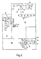
- Figure 3 shows an example of an application diagram of a lighting plant implemented, in accordance with the present invention, in a shed of a factory.
- the board contains (not illustrated in figure 3 ) two 16 Ampere three-phase disconnecting switches, each of which supplies different single-phase electric lines 19 of electric supply of the lighting apparatus 11.
- a first disconnecting switch placed on the left side of the portion 35 of the shed, supplies six electric lines 19, each with a 16 Ampere single-phase switch 18, which pilots six lighting apparatus 11, while a second disconnecting switch, placed on the right side of the portion 35 of the shed, supplies ten electric lines 19, each with a 16 Ampere single-phase switch 18, which pilots six lighting apparatus 11; an eleventh electric line 19 pilots four apparatus 11 used for the lighting of the signallers 29 of exodus routes.
- one hundred lighting apparatus 11 of the type with two fluorescent lamps of 58 Watt each are connected to this board 24 of the area 35 of the shed.
- control station 27 In the same space 35 of the shed, there is the control station 27, provided with GSM modem 43.
- the three electric supply lines 19 of the existing lighting apparatus 11 are controlled by three switches 18, relayed to obtain various ways of switching on from several points of the space 37.
- the three electric supply lines 19 are connected respectively to fourteen, thirteen and seventeen lighting apparatus 11 for a total of 44 apparatus, each having two fluorescent lamps of 58 Watt each.
- a third board 24 which houses a 16 ampere three-phase disconnecting switch for the lighting section of such space 36.
- the three electric supply lines 19 of the existing lighting apparatus 11 are controlled by three switches 18, relayed to obtain various ways of switching on from several points of the space 36.
- the three electric supply lines 19 are connected respectively to twelve, twelve and ten lighting apparatus 11, for a total of 34 apparatus, each having two fluorescent lamps of 58 Watt each.
- the installation of the emergency function provides the placement of three emergency cabinets 10 close to the three boards 24, with each emergency cabinet 10 sized with batteries 13 of dimension suitable to assure the emergency lighting for the desired number of apparatus 11 and time, according to the established safety requirements.
- a size for obtaining the emergency function is exemplified below:
- the cabinet 10 of the area 35 is equipped with eighteen 12 Volt batteries, 7 Ampere/h each, in order to assure the emergency function for one hour.
- the size margin of the batteries is 2.7 since, with 560 watt in emergency, the nominal power available from the 1 C batteries is equal to nearly 1500 Watt/h.
- the cabinets 10 of the other zones 36, 37, less extended, can be equipped with smaller batteries, for example by 3.2 Ampere/h; each of those cabinets 10 will then contain eighteen 12 Volt, 3.2 Ampere/h, batteries; in this case, the size margin is greater than 3, having a nominal power of 690 Watt/h available.
- the cabinet 10 of the area 35 will be equipped with eighteen 12 Volt batteries, 18 Ampere/h each, in order to assure three autonomy hours, with a size margin of the batteries equal to 2.3 since the nominal power available from the batteries is equal to nearly 3900 Watt/h (1300 Watt * 3 hours).
- the 7 Ampere/h batteries assure however the required performances even in the case of three hours of autonomy, since in such case the power available is nearly 1500 Watt/h, i.e. 500 Watt * 3 hours and, therefore, the size margin remains greater than 2.
- the over-size of the batteries 13 allows to control simultaneously the switching on in emergency of all the lighting apparatus till 50% of the luminous flux (with 56 Ampere/h batteries 13).
- the batteries of the hermetic type, are housed in respective cabinets, on the ground and in the lowest position of the cabinets, and, thus, easily accessible.
- the batteries are easily replaceable, operate in the best possible conditions of temperature and recharging and are sized with good operating margins, without significantly affecting the total system cost, thanks to scale factors; therefore, a life of over 7 years is expected.
- the system diagnostics the batteries status and indicates to the user the need to replace them.
- the system is also highly innovative with regard to the mode of the emergency supply of the lighting apparatus, since the supply electric lines of the lighting apparatus share on the same two copper cables the lighting apparatus which function in ordinary way and those ones which function also in emergency and every lighting apparatus automatically recognizes the emergency condition on the basis of the type of supply present at its power terminals.
- any lighting apparatus can be programmed and configured by the control station of the system and is configured by radio to operate according to desired performance, which can also be changed at the will of the user at any time.
- the system is provided with supply emergency sources (the cabinets) of the distributed type, in the sense that the emergency cabinets are one for each supply board of the electric lighting lines and, therefore, every area retains its operation autonomy. Moreover, in case of fire, the risks due to possible interruptions of the cables linking the only source (the cabinet) and the various emergency areas related to it are avoided, as it can, instead, happen in the centralized plants with a single supply source which must serve more emergency areas; the radio connection of the emergency system assures, then, a high level of security.
Landscapes
- Engineering & Computer Science (AREA)
- Computer Networks & Wireless Communication (AREA)
- Business, Economics & Management (AREA)
- Emergency Management (AREA)
- Power Engineering (AREA)
- Circuit Arrangement For Electric Light Sources In General (AREA)
- Circuit Arrangements For Discharge Lamps (AREA)
Applications Claiming Priority (1)
| Application Number | Priority Date | Filing Date | Title |
|---|---|---|---|
| IT000030A ITVI20070030A1 (it) | 2007-01-31 | 2007-01-31 | Impianto di illuminazione di emergenza centralizzato a funzionalita' integrabile con la illuminazione ordinaria |
Publications (1)
| Publication Number | Publication Date |
|---|---|
| EP1953893A2 true EP1953893A2 (de) | 2008-08-06 |
Family
ID=39529331
Family Applications (1)
| Application Number | Title | Priority Date | Filing Date |
|---|---|---|---|
| EP08425046A Withdrawn EP1953893A2 (de) | 2007-01-31 | 2008-01-30 | Zentralisierte Notbeleuchtungsanlage mit in die normale Beleuchtung integrierten Funktionen |
Country Status (2)
| Country | Link |
|---|---|
| EP (1) | EP1953893A2 (de) |
| IT (1) | ITVI20070030A1 (de) |
Cited By (4)
| Publication number | Priority date | Publication date | Assignee | Title |
|---|---|---|---|---|
| EP2573630A1 (de) | 2011-09-23 | 2013-03-27 | RP-Technik e. K. | Notlichtbeleuchtungsanlage mit Datenkommunikationsfähigkeiten |
| NL1039722C2 (nl) * | 2012-07-12 | 2014-01-14 | B & W Invest B V | Installatiesysteem en werkwijze voor een kas. |
| EP3300460A1 (de) * | 2016-09-19 | 2018-03-28 | FiSCHER Akkumulatorentechnik GmbH | Automatisiertes erkennen der zuordnung von notleuchten zu stromkreisen |
| EP2477462B1 (de) | 2011-01-14 | 2020-08-26 | Eaton Intelligent Power Limited | Zentralversorgungssystem und Verfahren zum gleichzeitigen Dimmen einer Vielzahl von Leuchten |
-
2007
- 2007-01-31 IT IT000030A patent/ITVI20070030A1/it unknown
-
2008
- 2008-01-30 EP EP08425046A patent/EP1953893A2/de not_active Withdrawn
Cited By (7)
| Publication number | Priority date | Publication date | Assignee | Title |
|---|---|---|---|---|
| EP2477462B1 (de) | 2011-01-14 | 2020-08-26 | Eaton Intelligent Power Limited | Zentralversorgungssystem und Verfahren zum gleichzeitigen Dimmen einer Vielzahl von Leuchten |
| EP2573630A1 (de) | 2011-09-23 | 2013-03-27 | RP-Technik e. K. | Notlichtbeleuchtungsanlage mit Datenkommunikationsfähigkeiten |
| DE102011053883A1 (de) | 2011-09-23 | 2013-03-28 | Rp-Technik E.K. | Notlichtbeleuchtungsanlage mit Datenkommunikationsfähigkeiten |
| DE102011053883B4 (de) | 2011-09-23 | 2022-03-10 | Rp-Technik Gmbh | Notlichtbeleuchtungsanlage mit Datenkommunikationsfähigkeiten |
| NL1039722C2 (nl) * | 2012-07-12 | 2014-01-14 | B & W Invest B V | Installatiesysteem en werkwijze voor een kas. |
| EP3300460A1 (de) * | 2016-09-19 | 2018-03-28 | FiSCHER Akkumulatorentechnik GmbH | Automatisiertes erkennen der zuordnung von notleuchten zu stromkreisen |
| EP3451800A1 (de) * | 2016-09-19 | 2019-03-06 | FiSCHER Akkumulatorentechnik GmbH | Automatisiertes erkennen der zuordnung von notleuchten zu stromkreisen |
Also Published As
| Publication number | Publication date |
|---|---|
| ITVI20070030A1 (it) | 2008-08-01 |
Similar Documents
| Publication | Publication Date | Title |
|---|---|---|
| US20160356469A1 (en) | Supplemental, backup or emergency lighting systems and methods | |
| CN103026130B (zh) | 路灯系统 | |
| EP2692210B1 (de) | Beleuchtungsvorrichtung | |
| US20120319477A1 (en) | Lighting system | |
| US10333344B2 (en) | Emergency backup systems providing dimmed power | |
| CN106463956A (zh) | 可重新配置的电力控制系统 | |
| US4755804A (en) | System for feeding and controlling low intensity obstruction lights | |
| EP1953893A2 (de) | Zentralisierte Notbeleuchtungsanlage mit in die normale Beleuchtung integrierten Funktionen | |
| CN102972096A (zh) | 数字可寻址照明接口控制器 | |
| US20140252948A1 (en) | Elevator interior illumination | |
| WO2013070279A1 (en) | Lighting system | |
| CN109633261B (zh) | 一种具有通信功能的模块化多回路计量系统 | |
| JP6252927B2 (ja) | 配電システムおよびそれに用いられる配線器具 | |
| JP2008043000A (ja) | 直流配電システム | |
| ES2900542T3 (es) | Bloque de luz de emergencia, instalación de alumbrado de emergencia y elemento de luz de emergencia | |
| CN108631433A (zh) | 一种数据机房柜间能量调度管理系统及方法 | |
| JP2012253842A (ja) | 電力供給システム | |
| KR20220142826A (ko) | 신재생에너지 또는 계통전력을 전력원으로 하는 ess가 구비된 가정용 예비전력 절체 관리 시스템 | |
| JP5443967B2 (ja) | 直流配電システム | |
| EP2571120B1 (de) | Anschlussvorrichtung für stromwandler | |
| US7659675B2 (en) | Device for illuminating the stope support at a longwall face | |
| RU109340U1 (ru) | БЛОК РАСПРЕДЕЛИТЕЛЬНЫЙ ПЕРЕМЕННОГО ТОКА БРПрТ | |
| CN218449590U (zh) | 三电源切换电路及单相三电源切换控制装置 | |
| RU2450405C1 (ru) | Выпрямительно-стабилизирующее устройство | |
| CN212518533U (zh) | 用于水务监测站点电源监测的ups终端 |
Legal Events
| Date | Code | Title | Description |
|---|---|---|---|
| PUAI | Public reference made under article 153(3) epc to a published international application that has entered the european phase |
Free format text: ORIGINAL CODE: 0009012 |
|
| AK | Designated contracting states |
Kind code of ref document: A2 Designated state(s): AT BE BG CH CY CZ DE DK EE ES FI FR GB GR HR HU IE IS IT LI LT LU LV MC MT NL NO PL PT RO SE SI SK TR |
|
| AX | Request for extension of the european patent |
Extension state: AL BA MK RS |
|
| STAA | Information on the status of an ep patent application or granted ep patent |
Free format text: STATUS: THE APPLICATION IS DEEMED TO BE WITHDRAWN |
|
| 18D | Application deemed to be withdrawn |
Effective date: 20130801 |