EP1953858A1 - Fuel cell - Google Patents
Fuel cell Download PDFInfo
- Publication number
- EP1953858A1 EP1953858A1 EP06822794A EP06822794A EP1953858A1 EP 1953858 A1 EP1953858 A1 EP 1953858A1 EP 06822794 A EP06822794 A EP 06822794A EP 06822794 A EP06822794 A EP 06822794A EP 1953858 A1 EP1953858 A1 EP 1953858A1
- Authority
- EP
- European Patent Office
- Prior art keywords
- fuel cell
- fuel
- gas
- reformer
- cell stacks
- Prior art date
- Legal status (The legal status is an assumption and is not a legal conclusion. Google has not performed a legal analysis and makes no representation as to the accuracy of the status listed.)
- Granted
Links
Images

Classifications
-
- H—ELECTRICITY
- H01—ELECTRIC ELEMENTS
- H01M—PROCESSES OR MEANS, e.g. BATTERIES, FOR THE DIRECT CONVERSION OF CHEMICAL ENERGY INTO ELECTRICAL ENERGY
- H01M8/00—Fuel cells; Manufacture thereof
- H01M8/10—Fuel cells with solid electrolytes
- H01M8/12—Fuel cells with solid electrolytes operating at high temperature, e.g. with stabilised ZrO2 electrolyte
-
- C—CHEMISTRY; METALLURGY
- C01—INORGANIC CHEMISTRY
- C01B—NON-METALLIC ELEMENTS; COMPOUNDS THEREOF; METALLOIDS OR COMPOUNDS THEREOF NOT COVERED BY SUBCLASS C01C
- C01B3/00—Hydrogen; Gaseous mixtures containing hydrogen; Separation of hydrogen from mixtures containing it; Purification of hydrogen
- C01B3/02—Production of hydrogen or of gaseous mixtures containing a substantial proportion of hydrogen
- C01B3/32—Production of hydrogen or of gaseous mixtures containing a substantial proportion of hydrogen by reaction of gaseous or liquid organic compounds with gasifying agents, e.g. water, carbon dioxide, air
- C01B3/34—Production of hydrogen or of gaseous mixtures containing a substantial proportion of hydrogen by reaction of gaseous or liquid organic compounds with gasifying agents, e.g. water, carbon dioxide, air by reaction of hydrocarbons with gasifying agents
- C01B3/38—Production of hydrogen or of gaseous mixtures containing a substantial proportion of hydrogen by reaction of gaseous or liquid organic compounds with gasifying agents, e.g. water, carbon dioxide, air by reaction of hydrocarbons with gasifying agents using catalysts
-
- H—ELECTRICITY
- H01—ELECTRIC ELEMENTS
- H01M—PROCESSES OR MEANS, e.g. BATTERIES, FOR THE DIRECT CONVERSION OF CHEMICAL ENERGY INTO ELECTRICAL ENERGY
- H01M8/00—Fuel cells; Manufacture thereof
- H01M8/04—Auxiliary arrangements, e.g. for control of pressure or for circulation of fluids
- H01M8/04007—Auxiliary arrangements, e.g. for control of pressure or for circulation of fluids related to heat exchange
-
- H—ELECTRICITY
- H01—ELECTRIC ELEMENTS
- H01M—PROCESSES OR MEANS, e.g. BATTERIES, FOR THE DIRECT CONVERSION OF CHEMICAL ENERGY INTO ELECTRICAL ENERGY
- H01M8/00—Fuel cells; Manufacture thereof
- H01M8/06—Combination of fuel cells with means for production of reactants or for treatment of residues
- H01M8/0606—Combination of fuel cells with means for production of reactants or for treatment of residues with means for production of gaseous reactants
- H01M8/0612—Combination of fuel cells with means for production of reactants or for treatment of residues with means for production of gaseous reactants from carbon-containing material
- H01M8/0625—Combination of fuel cells with means for production of reactants or for treatment of residues with means for production of gaseous reactants from carbon-containing material in a modular combined reactor/fuel cell structure
-
- H—ELECTRICITY
- H01—ELECTRIC ELEMENTS
- H01M—PROCESSES OR MEANS, e.g. BATTERIES, FOR THE DIRECT CONVERSION OF CHEMICAL ENERGY INTO ELECTRICAL ENERGY
- H01M8/00—Fuel cells; Manufacture thereof
- H01M8/24—Grouping of fuel cells, e.g. stacking of fuel cells
- H01M8/241—Grouping of fuel cells, e.g. stacking of fuel cells with solid or matrix-supported electrolytes
- H01M8/2425—High-temperature cells with solid electrolytes
- H01M8/2432—Grouping of unit cells of planar configuration
-
- H—ELECTRICITY
- H01—ELECTRIC ELEMENTS
- H01M—PROCESSES OR MEANS, e.g. BATTERIES, FOR THE DIRECT CONVERSION OF CHEMICAL ENERGY INTO ELECTRICAL ENERGY
- H01M8/00—Fuel cells; Manufacture thereof
- H01M8/24—Grouping of fuel cells, e.g. stacking of fuel cells
- H01M8/2457—Grouping of fuel cells, e.g. stacking of fuel cells with both reactants being gaseous or vaporised
-
- H—ELECTRICITY
- H01—ELECTRIC ELEMENTS
- H01M—PROCESSES OR MEANS, e.g. BATTERIES, FOR THE DIRECT CONVERSION OF CHEMICAL ENERGY INTO ELECTRICAL ENERGY
- H01M8/00—Fuel cells; Manufacture thereof
- H01M8/24—Grouping of fuel cells, e.g. stacking of fuel cells
- H01M8/2465—Details of groupings of fuel cells
- H01M8/2483—Details of groupings of fuel cells characterised by internal manifolds
-
- H—ELECTRICITY
- H01—ELECTRIC ELEMENTS
- H01M—PROCESSES OR MEANS, e.g. BATTERIES, FOR THE DIRECT CONVERSION OF CHEMICAL ENERGY INTO ELECTRICAL ENERGY
- H01M8/00—Fuel cells; Manufacture thereof
- H01M8/24—Grouping of fuel cells, e.g. stacking of fuel cells
- H01M8/249—Grouping of fuel cells, e.g. stacking of fuel cells comprising two or more groupings of fuel cells, e.g. modular assemblies
-
- C—CHEMISTRY; METALLURGY
- C01—INORGANIC CHEMISTRY
- C01B—NON-METALLIC ELEMENTS; COMPOUNDS THEREOF; METALLOIDS OR COMPOUNDS THEREOF NOT COVERED BY SUBCLASS C01C
- C01B2203/00—Integrated processes for the production of hydrogen or synthesis gas
- C01B2203/02—Processes for making hydrogen or synthesis gas
- C01B2203/0205—Processes for making hydrogen or synthesis gas containing a reforming step
- C01B2203/0227—Processes for making hydrogen or synthesis gas containing a reforming step containing a catalytic reforming step
-
- C—CHEMISTRY; METALLURGY
- C01—INORGANIC CHEMISTRY
- C01B—NON-METALLIC ELEMENTS; COMPOUNDS THEREOF; METALLOIDS OR COMPOUNDS THEREOF NOT COVERED BY SUBCLASS C01C
- C01B2203/00—Integrated processes for the production of hydrogen or synthesis gas
- C01B2203/06—Integration with other chemical processes
- C01B2203/066—Integration with other chemical processes with fuel cells
-
- C—CHEMISTRY; METALLURGY
- C01—INORGANIC CHEMISTRY
- C01B—NON-METALLIC ELEMENTS; COMPOUNDS THEREOF; METALLOIDS OR COMPOUNDS THEREOF NOT COVERED BY SUBCLASS C01C
- C01B2203/00—Integrated processes for the production of hydrogen or synthesis gas
- C01B2203/08—Methods of heating or cooling
- C01B2203/0805—Methods of heating the process for making hydrogen or synthesis gas
- C01B2203/0838—Methods of heating the process for making hydrogen or synthesis gas by heat exchange with exothermic reactions, other than by combustion of fuel
-
- Y—GENERAL TAGGING OF NEW TECHNOLOGICAL DEVELOPMENTS; GENERAL TAGGING OF CROSS-SECTIONAL TECHNOLOGIES SPANNING OVER SEVERAL SECTIONS OF THE IPC; TECHNICAL SUBJECTS COVERED BY FORMER USPC CROSS-REFERENCE ART COLLECTIONS [XRACs] AND DIGESTS
- Y02—TECHNOLOGIES OR APPLICATIONS FOR MITIGATION OR ADAPTATION AGAINST CLIMATE CHANGE
- Y02E—REDUCTION OF GREENHOUSE GAS [GHG] EMISSIONS, RELATED TO ENERGY GENERATION, TRANSMISSION OR DISTRIBUTION
- Y02E60/00—Enabling technologies; Technologies with a potential or indirect contribution to GHG emissions mitigation
- Y02E60/30—Hydrogen technology
- Y02E60/50—Fuel cells
-
- Y—GENERAL TAGGING OF NEW TECHNOLOGICAL DEVELOPMENTS; GENERAL TAGGING OF CROSS-SECTIONAL TECHNOLOGIES SPANNING OVER SEVERAL SECTIONS OF THE IPC; TECHNICAL SUBJECTS COVERED BY FORMER USPC CROSS-REFERENCE ART COLLECTIONS [XRACs] AND DIGESTS
- Y02—TECHNOLOGIES OR APPLICATIONS FOR MITIGATION OR ADAPTATION AGAINST CLIMATE CHANGE
- Y02P—CLIMATE CHANGE MITIGATION TECHNOLOGIES IN THE PRODUCTION OR PROCESSING OF GOODS
- Y02P20/00—Technologies relating to chemical industry
- Y02P20/10—Process efficiency
- Y02P20/129—Energy recovery, e.g. by cogeneration, H2recovery or pressure recovery turbines
-
- Y—GENERAL TAGGING OF NEW TECHNOLOGICAL DEVELOPMENTS; GENERAL TAGGING OF CROSS-SECTIONAL TECHNOLOGIES SPANNING OVER SEVERAL SECTIONS OF THE IPC; TECHNICAL SUBJECTS COVERED BY FORMER USPC CROSS-REFERENCE ART COLLECTIONS [XRACs] AND DIGESTS
- Y02—TECHNOLOGIES OR APPLICATIONS FOR MITIGATION OR ADAPTATION AGAINST CLIMATE CHANGE
- Y02P—CLIMATE CHANGE MITIGATION TECHNOLOGIES IN THE PRODUCTION OR PROCESSING OF GOODS
- Y02P20/00—Technologies relating to chemical industry
- Y02P20/50—Improvements relating to the production of bulk chemicals
- Y02P20/52—Improvements relating to the production of bulk chemicals using catalysts, e.g. selective catalysts
Definitions
- the present invention relates to an internal reforming fuel cell, in particular, a fuel cell in which the power generation efficiency is improved by reforming fuel at a high conversion rate.
- a fuel reformer is required to reform such a hydrocarbon gas (raw fuel gas) into a hydrogen rich gas.
- the above-described reforming reaction is an endothermic reaction, and for the purpose of performing a reforming reaction with such a satisfactory conversion rate that the residual amount of methane is 1% or less, it is necessary to heat a reforming catalyst in a fuel reformer at least to 640°C, and preferably to 700°C or higher. Accordingly, an internal reforming fuel cell is designed in such a way that the thermal energy required for the reforming reaction is obtained from the high temperature exhaust gas discharged from a fuel cell stack (see, for example, Patent Document 1).
- An object of the present invention is to provide a highly efficient fuel cell having a fuel reformer which can efficiently recover the exhaust heat from fuel cell stacks and can realize high conversion.
- a fuel cell comprising a plurality of fuel cell stacks placed in a housing, each fuel cell stack being formed by laminating a large number of power generating cells, wherein at least four fuel cell stacks are squarely-arranged (arranged in a square grid pattern) in a plane direction in the housing, and wherein a fuel reformer filled with a reforming catalyst is arranged in a cross shape in between the mutually facing sides of the fuel cell stacks.
- the fuel reformer is preferably formed in a cross shape capable of fitting in between the mutually facing sides of the fuel cell stacks.
- the above-described fuel cell can be configured in such a way that a first buffer zone in which no reforming catalyst is filled is provided in the gas inlet portion in the fuel reformer, and a second buffer zone in which no reforming catalyst is filled is provided in the gas outlet portion in the fuel reformer.
- the present invention can be applied to a solid oxide fuel cell having a sealless structure which discharges a residual gas having not been used in the power generation reaction from the peripheral portion of each of the power generating cells.
- the fuel reformer is disposed in a central portion of the housing, the central portion being surrounded by the plurality of fuel cell stacks so as to be an accumulation area of radiated heat. Consequently, the fuel reformer effectively receives the heat radiated from the sides, facing to the reformer, of each of the stacks, to carry out fuel reforming at a sufficiently high reforming temperature at a high conversion rate; thus a hydrogen-rich reformed gas extremely low in the residual methane content can be obtained to thereby enable highly efficient power generation.
- a mixed gas for example, a mixed gas composed of town gas and steam
- a mixed gas introduced from the gas inlet is made to diffuse in fully spreading manner in the first buffer zone so as to be evenly and uniformly supplied to the interior (to the interior of the catalyst layer) of each section of the cross-shaped reformer, and hence the whole reforming catalyst in the reformer is effectively applied to enable efficient reforming to be carried out.
- the fuel cell stacks are prevented from unnecessary cooling caused by the cooling effect due to the endothermic reaction; and the reformed gas generated in each section of the cross-shaped reformer is received in the second buffer zone, thus the reformed gas is evenly supplied to each of the fuel cell stacks, and accordingly, well-balanced power generation is carried out in between the fuel cell stacks.
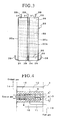
- Figure 1 shows the internal structure of a solid oxide fuel cell to which the present invention is applied
- Figure 2 shows a plan view of a fuel reformer according to the present invention
- Figure 3 shows a side view of the fuel reformer
- Figure 4 shows the configuration of a main part of a fuel cell stack.
- reference numeral 1 denotes a solid oxide fuel cell
- reference numeral 2 denotes a housing (can) in which the inner wall thereof is attached and covered with a heat insulating material
- reference numeral 3 denotes a fuel cell stack disposed inside the housing 2 so as for the lamination direction to be vertical.
- the solid oxide fuel cell 1 is a high-power fuel cell (fuel cell module) in which four fuel cell stacks are squarely-arranged in a plane direction in the housing 2 (on a circle with the center thereof located at the center of the housing 2), and further four tiers of fuel cell stacks are disposed in the heightwise direction, and thus sixteen fuel cell stacks 3 in total are assembled and disposed.
- the above-described fuel cell stack 3 has a structure in which a power generating cell 7 including a fuel electrode layer 5 disposed on one side of a solid electrolyte layer 4 and an air electrode layer (oxidant electrode layer) 6 disposed on the other side of the solid electrolyte layer 4, a fuel electrode current collector 8 outside the fuel electrode layer 5, an air electrode current collector (oxidant electrode current collector) 9 outside the air electrode layer 6, and separators 10 respectively disposed outside the current collectors 8 and 9 are sequentially laminated in this order, and this lamination is repeated so that the structure has a large lamination number.
- the solid electrolyte layer 4 is formed of a stabilized zirconia doped with yttria (YSZ) or the like.
- the fuel electrode layer 5 is formed of a metal such as Ni or a cermet such as Ni-YSZ.
- the air electrode layer 6 is formed of LaMnO 3 , LaCoO 3 or the like.
- the fuel electrode current collector 8 is formed of a spongy porous sintered metallic plate made of Ni or the like.
- the air electrode current collector 9 is formed of a spongy porous sintered metallic plate made of Ag or the like.
- the separator 10 is formed of stainless steel or the like.
- the separator 10 has a function of electrically connecting the power generating cells 7, and of supplying the reaction gases to the power generating cells 7, and is provided with a fuel gas passage 11 which introduces the fuel gas, supplied from the fuel gas manifold 13, from the outer peripheral surface of the separator 10 and discharges the fuel gas from a nearly central portion of the separator 10 facing the fuel electrode current collector 8 and with an oxidant gas passage 12 which introduces the oxidant gas, supplied from an oxidant gas manifold 14, from the outer peripheral surface of the separator 10 and discharges the oxidant gas from a nearly central portion of the separator 10 facing the air electrode current collector 9.
- the solid oxide fuel cell 1 has a sealless structure in which no gas leakage preventing seal is provided in the peripheral portion of the power generating cell 7.
- the fuel gas and the oxidant gas (air) discharged toward the power generating cell 7 from the nearly central portion of the separator 10, respectively, through the fuel gas passage 11 and the oxidant gas passage 12, are supplied in a uniform distribution to the whole area of the fuel electrode layer 5 and to the whole area of the air electrode layer 6 while the fuel gas and the oxidant gas are being made to diffuse toward the peripheral portion of the power generating cell 7 so as to allow the power generating reaction to take place; and the residual gas (exhaust gas) remaining unconsumed in the power generating reaction is freely discharged to the outside from the peripheral portion of the power generating cell 7.
- an exhaust gas pipe 19a is provided in the top portion of the housing 2 for the purpose of discharging to the outside the high-temperature exhaust gas having been discharged into the internal space of the housing 2.
- a fuel heat exchanger 20 the fuel reformer 30 subsequent to the fuel heat exchanger 20 (located downstream of the fuel heat exchanger 20), an air heat exchanger 40 for preheating air and the like are disposed.
- a fuel gas supply pipe 15 and a water supply pipe 17 are connected to the fuel heat exchanger 20, and an oxidant gas supply pipe 16 is connected to the air heat exchanger 40.
- the heat exchangers 20 and 40 and the fuel reformer 30 are respectively disposed in appropriate positions in the vicinity of the fuel cell stacks 3 such that these heat exchangers 20 and 40 and the fuel reformer 30 can obtain sufficient heat conductance and sufficient radiation heat from the fuel cell stacks 3, so that efficient heat recovery is considered to be achieved in the housing 2.
- the fuel reformer 30 is formed in a cross shape employing integrated structure, and is disposed as shown in Figure 2 so as to make use of the gap between the mutually facing sides of the fuel cell stacks 3 squarely-arranged on a circle with the center thereof located at the center of the housing 2, in such a way that the fuel reformer 30 is mounted and fixed on a stack mounting base 37 disposed on the bottom of the housing 2 so that the fuel reformer 30 shares the same mounting plane with the plurality of fuel cell stacks 3.
- a gas inlet 31 is provided at the upper end of each of flat box-shaped wing sections 30a, 30b, 30c and 30d
- a gas outlet 34 is provided at the lower end of each of the wing sections 30a, 30b, 30c and 30d
- each of the gas inlets 31 at the upper end is connected to the above-described fuel heat exchanger 20 through the intermediary of an upper pipe 38
- each of the gas outlets 34 at the lower end is connected to the fuel gas manifold 13 shown in Figure 4 through the intermediary of a lower pipe 39.
- a reforming catalyst 33 is filled in the interior of the fuel reformer 30, spatial zones (the first buffer zone 32 and the second buffer zone 35) in each of which no reforming catalyst 33 is filled are provided in the gas inlet portion (the upper portion) of the reformer and the gas outlet portion (the lower portion) of the reformer, respectively.
- the zone filled with the reforming catalyst 33 and the upper and lower non-filled zones are partitioned with punching plates 36 having air permeability, and the reforming catalyst 33 is filled in the zone partitioned and formed with the punching plates 36.
- Examples usable as the reforming catalyst 33 include a pellet catalyst in which a Ni-based or Ru-based hydrocarbon catalyst is attached as the active component to the surface of a granular carrier and a honeycomb catalyst in which a catalyst itself is made to take a honeycomb structure.
- a mixed gas composed of a hydrocarbon gas (for example, town gas) as the raw fuel gas and steam is preheated in the fuel heat exchanger 20 to be converted into a high temperature mixed gas, which is guided to the fuel reformer 30 through the upper pipe 38 and introduced into the reformer 30 from the gas inlet 31 of each of the wing sections 30a to 30d.
- the introduced gas is brought into contact with the reforming catalyst 33 in the respective wing sections 30a to 30d to allow the steam reforming reaction of the hydrocarbon gas to take place.
- This reforming reaction is an endothermic reaction, and the heat (650 to 800°C) required for the reforming reaction is obtained by recovering the exhaust heat from the fuel cell stacks 3.
- the reformed gas obtained by the reforming reaction conducted in the fuel reformer 30 is introduced from each of the gas outlets 34 located downstream of the fuel reformer 30 to the fuel gas manifold 13 of each of the fuel cell stacks 3 through each of the lower pipes 39.
- the reaction gas flows in each of the fuel cell stacks 3 are as illustrated in Figure 4 .
- the fuel reformer 30 is disposed in a central portion of the housing 2, the central portion being surrounded by at least four fuel cell stacks 3 disposed in a plane direction, so as to be an accumulation area of the radiated heat from the fuel cell stacks 3. Consequently, in this heat accumulation area, the fuel reformer 30 effectively receives the heat radiated from the sides, facing to the reformer, of each of the stacks, so as to recover a sufficient reforming temperature and to thereby carry out fuel reforming at a high conversion rate; thus a hydrogen-rich reformed gas extremely low in the residual methane content can be obtained and supplied to the power generating cells 7, and hence a highly efficient power generation is enabled.
- the outlet temperature of the fuel reformer 30 (reforming catalyst 33) can be ensured to be high enough to enable stable reforming, namely, to be 650°C or higher, and hence the content of the residual methane can be actually made to be and maintained at 1% or less.
- a mixed gas introduced from the gas inlets 31 is made to diffusely spread throughout the first buffer zone 32 so as to be evenly and uniformly supplied to the reforming catalyst 33 in the interior of each of the cross-shaped wing sections 30a to 30d, and hence the whole reforming catalyst in the reformer is effectively utilized to enable efficient reforming to be carried out.
- this spatial zone suppresses the heat conduction to the stack mounting base 37, accordingly the fuel cell stacks 3 are prevented from unnecessary cooling, from the bottoms of the fuel cell stacks 3 through the stack mounting base 37, caused by the cooling effect during the endothermic reaction; and the reformed gas generated in each of the wing sections 30a to 30d is received in the second buffer zone to be thereafter distributed to and introduced into each of the lower pipes 39, thus the reformed gas is evenly supplied to each of the fuel cell stacks 3, through the lower pipes 39, and accordingly, well-balanced power generation is carried out in between the fuel cell stacks 3.
- the fuel reformer 30 is made to be a cross shape so that it can fit in between the mutually facing sides of the fuel cell stacks 3.
- a configuration in which a flat box-shaped fuel reformer is disposed in between each of the pairs of mutually facing sides of the stacks may also be adopted.
- a highly efficient fuel cell having a high conversion rate fuel reformer capable of efficiently recovering the exhaust heat from fuel cell stacks can be provided.
Abstract
Description
- The present invention relates to an internal reforming fuel cell, in particular, a fuel cell in which the power generation efficiency is improved by reforming fuel at a high conversion rate.
- When a hydrocarbon fuel gas such as town gas is used as a reaction gas to be introduced into a fuel cell, a fuel reformer is required to reform such a hydrocarbon gas (raw fuel gas) into a hydrogen rich gas.
- In the fuel reformer, steam is mixed with the raw fuel gas to yield a mixed gas, and thereafter hydrogen is generated, for example, by allowing these two gases to react with each other in a high-temperature environment set at 350°C or higher.
Specifically, in the reforming reaction (steam reforming), first, methane as the raw fuel gas and steam are allowed to react with each other to yield hydrogen and carbon monoxide, and further, the carbon monoxide thus generated and steam react with each other to yield hydrogen along with carbon dioxide.
These reactions are represented in terms of reaction formulas as follows:
CH4 + H2O → H2 + CO
CO + H2O → 3H2 + CO2
- The above-described reforming reaction is an endothermic reaction, and for the purpose of performing a reforming reaction with such a satisfactory conversion rate that the residual amount of methane is 1% or less, it is necessary to heat a reforming catalyst in a fuel reformer at least to 640°C, and preferably to 700°C or higher. Accordingly, an internal reforming fuel cell is designed in such a way that the thermal energy required for the reforming reaction is obtained from the high temperature exhaust gas discharged from a fuel cell stack (see, for example, Patent Document 1).
- Incidentally, for example, in a solid oxide fuel cell, when it is a high-temperature operation type operated at temperatures in the vicinity of 1000°C, it is relatively easy to recover the thermal energy required for fuel reforming; however, when it is a low-temperature operation type operated at temperatures in the vicinity of 700°C, it becomes difficult to sufficiently recover the heat required for the endothermic reaction because the discharged thermal energy is smaller than that in the aforementioned high-temperature operation type. When sufficient energy is not supplied to the fuel reformer, the reforming reaction becomes insufficient, leading to a fear that no hydrogen rich reformed gas is obtained.
When a large amount of methane is contained in the reformed gas due to insufficient reforming, the carbon in the reformed gas is deposited in the power generating cells to drastically degrade the cell performance, and it interferes with efficient power generation. - Patent Document 1: Japanese Patent Laid-Open No.
2005-19034 - The present invention was achieved in view of such problems as described above. An object of the present invention is to provide a highly efficient fuel cell having a fuel reformer which can efficiently recover the exhaust heat from fuel cell stacks and can realize high conversion.
- For the purpose of achieving the above-described object, according to the present invention, there is provided a fuel cell comprising a plurality of fuel cell stacks placed in a housing, each fuel cell stack being formed by laminating a large number of power generating cells, wherein at least four fuel cell stacks are squarely-arranged (arranged in a square grid pattern) in a plane direction in the housing, and wherein a fuel reformer filled with a reforming catalyst is arranged in a cross shape in between the mutually facing sides of the fuel cell stacks.
- In the above-described fuel cell, the fuel reformer is preferably formed in a cross shape capable of fitting in between the mutually facing sides of the fuel cell stacks.
- Additionally, the above-described fuel cell can be configured in such a way that a first buffer zone in which no reforming catalyst is filled is provided in the gas inlet portion in the fuel reformer, and a second buffer zone in which no reforming catalyst is filled is provided in the gas outlet portion in the fuel reformer.
- The present invention can be applied to a solid oxide fuel cell having a sealless structure which discharges a residual gas having not been used in the power generation reaction from the peripheral portion of each of the power generating cells.
- According to the present invention, the fuel reformer is disposed in a central portion of the housing, the central portion being surrounded by the plurality of fuel cell stacks so as to be an accumulation area of radiated heat. Consequently, the fuel reformer effectively receives the heat radiated from the sides, facing to the reformer, of each of the stacks, to carry out fuel reforming at a sufficiently high reforming temperature at a high conversion rate; thus a hydrogen-rich reformed gas extremely low in the residual methane content can be obtained to thereby enable highly efficient power generation.
- Additionally, by providing the first buffer zone in the gas inlet portion in the fuel reformer, a mixed gas (for example, a mixed gas composed of town gas and steam) introduced from the gas inlet is made to diffuse in fully spreading manner in the first buffer zone so as to be evenly and uniformly supplied to the interior (to the interior of the catalyst layer) of each section of the cross-shaped reformer, and hence the whole reforming catalyst in the reformer is effectively applied to enable efficient reforming to be carried out.
- Additionally, by providing the second buffer zone in the gas outlet portion in the fuel reformer, the fuel cell stacks are prevented from unnecessary cooling caused by the cooling effect due to the endothermic reaction; and the reformed gas generated in each section of the cross-shaped reformer is received in the second buffer zone, thus the reformed gas is evenly supplied to each of the fuel cell stacks, and accordingly, well-balanced power generation is carried out in between the fuel cell stacks.
-
-
Figure 1 is a sectional view illustrating the internal structure of a solid oxide fuel cell according to the present invention; -
Figure 2 is a top view of a fuel reformer according to the present invention; -
Figure 3 is a side view of the fuel reformer according to the present invention; and -
Figure 4 is a schematic view illustrating the configuration of a main part of a fuel cell stack according to the present invention, with the illustrated gas flow at the time of operation. -
- 1
- Fuel cell (solid oxide fuel cell)
- 2
- Housing
- 3
- Fuel cell stack
- 7
- Power generating cell
- 30
- Fuel reformer
- 31
- Gas inlet
- 32
- First buffer zone
- 33
- Reforming catalyst
- 34
- Gas outlet
- 35
- Second buffer zone
- Hereinafter, an embodiment of the present invention is described with reference to
Figures 1 to 4 . -
Figure 1 shows the internal structure of a solid oxide fuel cell to which the present invention is applied,Figure 2 shows a plan view of a fuel reformer according to the present invention,Figure 3 shows a side view of the fuel reformer, andFigure 4 shows the configuration of a main part of a fuel cell stack. - In
Figure 1 , reference numeral 1 denotes a solid oxide fuel cell,reference numeral 2 denotes a housing (can) in which the inner wall thereof is attached and covered with aheat insulating material 18,reference numeral 3 denotes a fuel cell stack disposed inside thehousing 2 so as for the lamination direction to be vertical. In the present embodiment, the solid oxide fuel cell 1 is a high-power fuel cell (fuel cell module) in which four fuel cell stacks are squarely-arranged in a plane direction in the housing 2 (on a circle with the center thereof located at the center of the housing 2), and further four tiers of fuel cell stacks are disposed in the heightwise direction, and thus sixteenfuel cell stacks 3 in total are assembled and disposed. - As shown in
Figure 4 , the above-describedfuel cell stack 3 has a structure in which apower generating cell 7 including afuel electrode layer 5 disposed on one side of asolid electrolyte layer 4 and an air electrode layer (oxidant electrode layer) 6 disposed on the other side of thesolid electrolyte layer 4, a fuelelectrode current collector 8 outside thefuel electrode layer 5, an air electrode current collector (oxidant electrode current collector) 9 outside theair electrode layer 6, andseparators 10 respectively disposed outside thecurrent collectors 8 and 9 are sequentially laminated in this order, and this lamination is repeated so that the structure has a large lamination number. - The
solid electrolyte layer 4 is formed of a stabilized zirconia doped with yttria (YSZ) or the like. Thefuel electrode layer 5 is formed of a metal such as Ni or a cermet such as Ni-YSZ. Theair electrode layer 6 is formed of LaMnO3, LaCoO3 or the like. The fuel electrodecurrent collector 8 is formed of a spongy porous sintered metallic plate made of Ni or the like. The air electrode current collector 9 is formed of a spongy porous sintered metallic plate made of Ag or the like. Theseparator 10 is formed of stainless steel or the like. - The
separator 10 has a function of electrically connecting the power generatingcells 7, and of supplying the reaction gases to the power generatingcells 7, and is provided with afuel gas passage 11 which introduces the fuel gas, supplied from thefuel gas manifold 13, from the outer peripheral surface of theseparator 10 and discharges the fuel gas from a nearly central portion of theseparator 10 facing the fuel electrodecurrent collector 8 and with anoxidant gas passage 12 which introduces the oxidant gas, supplied from anoxidant gas manifold 14, from the outer peripheral surface of theseparator 10 and discharges the oxidant gas from a nearly central portion of theseparator 10 facing the air electrode current collector 9. - The solid oxide fuel cell 1 has a sealless structure in which no gas leakage preventing seal is provided in the peripheral portion of the
power generating cell 7. At the time of operation, as shown inFigure 4 , the fuel gas and the oxidant gas (air) discharged toward thepower generating cell 7 from the nearly central portion of theseparator 10, respectively, through thefuel gas passage 11 and theoxidant gas passage 12, are supplied in a uniform distribution to the whole area of thefuel electrode layer 5 and to the whole area of theair electrode layer 6 while the fuel gas and the oxidant gas are being made to diffuse toward the peripheral portion of thepower generating cell 7 so as to allow the power generating reaction to take place; and the residual gas (exhaust gas) remaining unconsumed in the power generating reaction is freely discharged to the outside from the peripheral portion of thepower generating cell 7. Additionally, as shown inFigure 1 , an exhaust gas pipe 19a is provided in the top portion of thehousing 2 for the purpose of discharging to the outside the high-temperature exhaust gas having been discharged into the internal space of thehousing 2. - Additionally, in the
housing 2, in addition to the above-described sixteenfuel cell stacks 3, afuel heat exchanger 20, thefuel reformer 30 subsequent to the fuel heat exchanger 20 (located downstream of the fuel heat exchanger 20), anair heat exchanger 40 for preheating air and the like are disposed. A fuelgas supply pipe 15 and awater supply pipe 17 are connected to thefuel heat exchanger 20, and an oxidantgas supply pipe 16 is connected to theair heat exchanger 40. Theheat exchangers fuel reformer 30 are respectively disposed in appropriate positions in the vicinity of thefuel cell stacks 3 such that theseheat exchangers fuel reformer 30 can obtain sufficient heat conductance and sufficient radiation heat from thefuel cell stacks 3, so that efficient heat recovery is considered to be achieved in thehousing 2. - In this connection, as has already been described, as a technique to improve the power generation efficiency of the fuel cell 1, it is effective to increase the conversion rate by increasing the reforming temperature in the above-described
reformer 30. - Accordingly, in the present embodiment, the
fuel reformer 30 is formed in a cross shape employing integrated structure, and is disposed as shown inFigure 2 so as to make use of the gap between the mutually facing sides of thefuel cell stacks 3 squarely-arranged on a circle with the center thereof located at the center of thehousing 2, in such a way that thefuel reformer 30 is mounted and fixed on astack mounting base 37 disposed on the bottom of thehousing 2 so that thefuel reformer 30 shares the same mounting plane with the plurality of fuel cell stacks 3. - In this
fuel reformer 30, agas inlet 31 is provided at the upper end of each of flat box-shapedwing sections gas outlet 34 is provided at the lower end of each of thewing sections gas inlets 31 at the upper end is connected to the above-describedfuel heat exchanger 20 through the intermediary of anupper pipe 38, and each of thegas outlets 34 at the lower end is connected to thefuel gas manifold 13 shown inFigure 4 through the intermediary of alower pipe 39. - As shown in
Figure 3 , although a reformingcatalyst 33 is filled in the interior of thefuel reformer 30, spatial zones (thefirst buffer zone 32 and the second buffer zone 35) in each of which no reformingcatalyst 33 is filled are provided in the gas inlet portion (the upper portion) of the reformer and the gas outlet portion (the lower portion) of the reformer, respectively. The zone filled with the reformingcatalyst 33 and the upper and lower non-filled zones (namely, thebuffer zones 32 and 35) are partitioned with punchingplates 36 having air permeability, and the reformingcatalyst 33 is filled in the zone partitioned and formed with the punchingplates 36. - Examples usable as the reforming
catalyst 33 include a pellet catalyst in which a Ni-based or Ru-based hydrocarbon catalyst is attached as the active component to the surface of a granular carrier and a honeycomb catalyst in which a catalyst itself is made to take a honeycomb structure. - In the above-described configuration, at the time of operation, a mixed gas composed of a hydrocarbon gas (for example, town gas) as the raw fuel gas and steam is preheated in the
fuel heat exchanger 20 to be converted into a high temperature mixed gas, which is guided to thefuel reformer 30 through theupper pipe 38 and introduced into thereformer 30 from thegas inlet 31 of each of the wing sections 30a to 30d. The introduced gas is brought into contact with the reformingcatalyst 33 in the respective wing sections 30a to 30d to allow the steam reforming reaction of the hydrocarbon gas to take place. This reforming reaction is an endothermic reaction, and the heat (650 to 800°C) required for the reforming reaction is obtained by recovering the exhaust heat from the fuel cell stacks 3. - The reformed gas obtained by the reforming reaction conducted in the
fuel reformer 30 is introduced from each of thegas outlets 34 located downstream of thefuel reformer 30 to thefuel gas manifold 13 of each of thefuel cell stacks 3 through each of thelower pipes 39. The reaction gas flows in each of thefuel cell stacks 3 are as illustrated inFigure 4 . - In the present embodiment, the
fuel reformer 30 is disposed in a central portion of thehousing 2, the central portion being surrounded by at least fourfuel cell stacks 3 disposed in a plane direction, so as to be an accumulation area of the radiated heat from the fuel cell stacks 3. Consequently, in this heat accumulation area, thefuel reformer 30 effectively receives the heat radiated from the sides, facing to the reformer, of each of the stacks, so as to recover a sufficient reforming temperature and to thereby carry out fuel reforming at a high conversion rate; thus a hydrogen-rich reformed gas extremely low in the residual methane content can be obtained and supplied to thepower generating cells 7, and hence a highly efficient power generation is enabled.
In particular, in the solid oxide fuel cell 1 having a sealless structure, high temperature exhaust gas is freely discharged from the sides of thefuel cell stacks 3 into the interior of thehousing 2 so as to extremely facilitate the exhaust heat recovery, and accordingly, the outlet temperature of the fuel reformer 30 (reforming catalyst 33) can be ensured to be high enough to enable stable reforming, namely, to be 650°C or higher, and hence the content of the residual methane can be actually made to be and maintained at 1% or less. - Additionally, by providing the
first buffer zone 32 in thegas inlet 31 portion in the upper portion of thefuel reformer 30, a mixed gas introduced from thegas inlets 31 is made to diffusely spread throughout thefirst buffer zone 32 so as to be evenly and uniformly supplied to the reformingcatalyst 33 in the interior of each of the cross-shaped wing sections 30a to 30d, and hence the whole reforming catalyst in the reformer is effectively utilized to enable efficient reforming to be carried out. - Additionally, by providing the
second buffer zone 35 in thegas outlet 34 portion in the lower portion of thefuel reformer 30, this spatial zone suppresses the heat conduction to thestack mounting base 37, accordingly thefuel cell stacks 3 are prevented from unnecessary cooling, from the bottoms of thefuel cell stacks 3 through thestack mounting base 37, caused by the cooling effect during the endothermic reaction; and the reformed gas generated in each of the wing sections 30a to 30d is received in the second buffer zone to be thereafter distributed to and introduced into each of thelower pipes 39, thus the reformed gas is evenly supplied to each of thefuel cell stacks 3, through thelower pipes 39, and accordingly, well-balanced power generation is carried out in between the fuel cell stacks 3. - As described above, in the present embodiment, the
fuel reformer 30 is made to be a cross shape so that it can fit in between the mutually facing sides of the fuel cell stacks 3. However, a configuration in which a flat box-shaped fuel reformer is disposed in between each of the pairs of mutually facing sides of the stacks may also be adopted.
Additionally, as for the fuel cell 1, description has been made on the configuration in which fourfuel cell stacks 3 are arranged in a plane direction and each of which is vertically-stacked in four tiers; however, needless to say, the number of tiers is not limited to the above-mentioned value. What matters is that the structure of the fuel cell is only required to be a structure in which the above-describedfuel reformer 30 is disposed in the central portion surrounded by thefuel cell stacks 3, where radiated heat from thestacks 3 accumulates. - As described above, according to the present invention, a highly efficient fuel cell having a high conversion rate fuel reformer capable of efficiently recovering the exhaust heat from fuel cell stacks can be provided.
Claims (5)
- A fuel cell comprising a plurality of fuel cell stacks placed in a housing, each fuel cell stack being formed by laminating a large number of power generating cells, wherein:at least four fuel cell stacks are squarely-arranged in a plane direction in the housing; anda fuel reformer filled with a reforming catalyst is arranged in a cross shape in between the mutually facing sides of the fuel cell stacks.
- The fuel cell according to claim 1, wherein the fuel reformer is formed in a cross shape capable of fitting in between the mutually facing sides of the fuel cell stacks.
- The fuel cell according to claim 2, wherein a first buffer zone in which no reforming catalyst is filled is provided in a gas inlet portion in the fuel reformer.
- The fuel cell according to claim 2, wherein a second buffer zone in which no reforming catalyst is filled is provided in a gas outlet portion in the fuel reformer.
- The fuel cell according to claim 1, wherein the fuel cell is a solid oxide fuel cell having a sealless structure which discharges a residual gas having not been used in a power generation reaction from the outer peripheral portion of each of the power generating cells.
Applications Claiming Priority (2)
| Application Number | Priority Date | Filing Date | Title |
|---|---|---|---|
| JP2005319627A JP5061450B2 (en) | 2005-11-02 | 2005-11-02 | Fuel cell |
| PCT/JP2006/321865 WO2007052704A1 (en) | 2005-11-02 | 2006-11-01 | Fuel cell |
Publications (3)
| Publication Number | Publication Date |
|---|---|
| EP1953858A1 true EP1953858A1 (en) | 2008-08-06 |
| EP1953858A4 EP1953858A4 (en) | 2009-11-25 |
| EP1953858B1 EP1953858B1 (en) | 2014-06-18 |
Family
ID=38005857
Family Applications (1)
| Application Number | Title | Priority Date | Filing Date |
|---|---|---|---|
| EP06822794.1A Not-in-force EP1953858B1 (en) | 2005-11-02 | 2006-11-01 | Fuel cell |
Country Status (4)
| Country | Link |
|---|---|
| US (1) | US8034496B2 (en) |
| EP (1) | EP1953858B1 (en) |
| JP (1) | JP5061450B2 (en) |
| WO (1) | WO2007052704A1 (en) |
Cited By (3)
| Publication number | Priority date | Publication date | Assignee | Title |
|---|---|---|---|---|
| EP1970988A1 (en) * | 2005-12-05 | 2008-09-17 | Mitsubishi Materials Corporation | Fuel cell |
| WO2010066460A1 (en) * | 2008-12-12 | 2010-06-17 | Ezelleron Gmbh | Fuel cell system with reformer |
| WO2012171796A1 (en) * | 2011-06-17 | 2012-12-20 | Siemens Aktiengesellschaft | Electric energy store |
Families Citing this family (11)
| Publication number | Priority date | Publication date | Assignee | Title |
|---|---|---|---|---|
| JP5109252B2 (en) * | 2005-12-05 | 2012-12-26 | 三菱マテリアル株式会社 | Fuel cell |
| JP5219441B2 (en) * | 2007-09-13 | 2013-06-26 | Jx日鉱日石エネルギー株式会社 | Fuel cell system |
| JP5113465B2 (en) * | 2007-09-18 | 2013-01-09 | 日本電信電話株式会社 | Flat fuel cell stack and module |
| JP2009245630A (en) * | 2008-03-28 | 2009-10-22 | Mitsubishi Materials Corp | Reformer and plate type solid oxide fuel cell using the same |
| JP5262241B2 (en) * | 2008-03-31 | 2013-08-14 | 三菱マテリアル株式会社 | Solid oxide fuel cell |
| KR101446195B1 (en) | 2008-05-08 | 2014-10-01 | 주식회사 동진쎄미켐 | Equipment for removing carbon dioxide for direct methanol fuel cell |
| JP6264544B2 (en) * | 2014-02-03 | 2018-01-24 | Toto株式会社 | Solid oxide fuel cell device |
| JP2015146266A (en) * | 2014-02-03 | 2015-08-13 | Toto株式会社 | solid oxide fuel cell device |
| JP2016177881A (en) * | 2015-03-18 | 2016-10-06 | 富士電機株式会社 | Fuel cell module |
| JP6715707B2 (en) | 2016-07-06 | 2020-07-01 | 日立造船株式会社 | Fuel cell system |
| JP7144369B2 (en) * | 2019-07-10 | 2022-09-29 | 日立造船株式会社 | fuel cell system |
Citations (4)
| Publication number | Priority date | Publication date | Assignee | Title |
|---|---|---|---|---|
| US5340664A (en) * | 1993-09-29 | 1994-08-23 | Ceramatec, Inc. | Thermally integrated heat exchange system for solid oxide electrolyte systems |
| DE19812155A1 (en) * | 1998-03-20 | 1999-09-30 | Forschungszentrum Juelich Gmbh | Arrangement for energy conversion comprising at least two fuel cell stacks and at least one reformer unit |
| DE10310642A1 (en) * | 2003-03-12 | 2004-09-23 | Forschungszentrum Jülich GmbH | High temperature fuel cell system in modular structure with planar cell stack and at least one component, e.g. after burner, reformer and heat exchanger, which is fitted directly on side of cell stack |
| WO2005069776A2 (en) * | 2004-01-22 | 2005-08-04 | Ion America Corporation | High temperature fuel cell system and method of operating same |
Family Cites Families (13)
| Publication number | Priority date | Publication date | Assignee | Title |
|---|---|---|---|---|
| US4877693A (en) * | 1985-12-23 | 1989-10-31 | Energy Research Corporation | Fuel cell apparatus for internal reforming |
| CA1278335C (en) * | 1985-12-23 | 1990-12-27 | Bernard S. Baker | Fuel cell apparatus with internal reforming |
| JPS62154548A (en) * | 1985-12-27 | 1987-07-09 | 株式会社小糸製作所 | Incandescent lamp |
| JPS63232275A (en) * | 1987-03-20 | 1988-09-28 | Mitsubishi Electric Corp | Fuel cell of lamination type |
| EP0398111A1 (en) * | 1989-05-18 | 1990-11-22 | Asea Brown Boveri Ag | Device for converting chemical energy of hydrocarbons to electrical energy by means of electrochemical high temperature process |
| JPH0831322B2 (en) * | 1989-09-20 | 1996-03-27 | 株式会社日立製作所 | Internal reforming fuel cell and power plant using the same |
| US4983471A (en) * | 1989-12-28 | 1991-01-08 | Westinghouse Electric Corp. | Electrochemical cell apparatus having axially distributed entry of a fuel-spent fuel mixture transverse to the cell lengths |
| JPH07272741A (en) * | 1994-03-31 | 1995-10-20 | Mitsubishi Heavy Ind Ltd | Module structure for cylindrical solid electrolytic fuel cell |
| DE4438555C1 (en) * | 1994-10-28 | 1996-03-07 | Mtu Friedrichshafen Gmbh | Fuel cell arrangement with reforming device |
| US6200696B1 (en) * | 1999-02-16 | 2001-03-13 | Energy Research Corporation | Internal reforming fuel cell assembly with simplified fuel feed |
| US7001684B2 (en) * | 2003-01-24 | 2006-02-21 | General Electric Company | Systems for planar fuel cell interconnect units |
| JP2005019034A (en) | 2003-06-24 | 2005-01-20 | Mitsubishi Materials Corp | Solid oxide fuel cell |
| US7335432B2 (en) * | 2004-04-30 | 2008-02-26 | Motorola, Inc. | Solid oxide fuel cell portable power source |
-
2005
- 2005-11-02 JP JP2005319627A patent/JP5061450B2/en not_active Expired - Fee Related
-
2006
- 2006-11-01 WO PCT/JP2006/321865 patent/WO2007052704A1/en active Application Filing
- 2006-11-01 US US12/084,480 patent/US8034496B2/en not_active Expired - Fee Related
- 2006-11-01 EP EP06822794.1A patent/EP1953858B1/en not_active Not-in-force
Patent Citations (4)
| Publication number | Priority date | Publication date | Assignee | Title |
|---|---|---|---|---|
| US5340664A (en) * | 1993-09-29 | 1994-08-23 | Ceramatec, Inc. | Thermally integrated heat exchange system for solid oxide electrolyte systems |
| DE19812155A1 (en) * | 1998-03-20 | 1999-09-30 | Forschungszentrum Juelich Gmbh | Arrangement for energy conversion comprising at least two fuel cell stacks and at least one reformer unit |
| DE10310642A1 (en) * | 2003-03-12 | 2004-09-23 | Forschungszentrum Jülich GmbH | High temperature fuel cell system in modular structure with planar cell stack and at least one component, e.g. after burner, reformer and heat exchanger, which is fitted directly on side of cell stack |
| WO2005069776A2 (en) * | 2004-01-22 | 2005-08-04 | Ion America Corporation | High temperature fuel cell system and method of operating same |
Non-Patent Citations (1)
| Title |
|---|
| See also references of WO2007052704A1 * |
Cited By (5)
| Publication number | Priority date | Publication date | Assignee | Title |
|---|---|---|---|---|
| EP1970988A1 (en) * | 2005-12-05 | 2008-09-17 | Mitsubishi Materials Corporation | Fuel cell |
| EP1970988A4 (en) * | 2005-12-05 | 2010-11-10 | Mitsubishi Materials Corp | Fuel cell |
| WO2010066460A1 (en) * | 2008-12-12 | 2010-06-17 | Ezelleron Gmbh | Fuel cell system with reformer |
| WO2012171796A1 (en) * | 2011-06-17 | 2012-12-20 | Siemens Aktiengesellschaft | Electric energy store |
| US9350054B2 (en) | 2011-06-17 | 2016-05-24 | Siemens Aktiengesellschaft | Electric energy store |
Also Published As
| Publication number | Publication date |
|---|---|
| US8034496B2 (en) | 2011-10-11 |
| US20090136813A1 (en) | 2009-05-28 |
| JP5061450B2 (en) | 2012-10-31 |
| EP1953858B1 (en) | 2014-06-18 |
| EP1953858A4 (en) | 2009-11-25 |
| JP2007128716A (en) | 2007-05-24 |
| WO2007052704A1 (en) | 2007-05-10 |
Similar Documents
| Publication | Publication Date | Title |
|---|---|---|
| US8034496B2 (en) | Fuel cell | |
| CA2397682C (en) | Multipurpose reversible electrochemical system | |
| EP1976047B1 (en) | Fuel cell | |
| EP0963617B1 (en) | Improved catalyst assembly for internal reforming fuel cell | |
| EP2212961B1 (en) | Fuel cell module | |
| EP1970988A1 (en) | Fuel cell | |
| AU2002219941A1 (en) | Multipurpose reversible electrochemical system | |
| EP2859606B1 (en) | Solid oxide fuel cell or solid oxide electrolyzing cell and method for operating such a cell | |
| JP4956946B2 (en) | Fuel cell | |
| US7972742B2 (en) | Tube type fuel cell to decrease current path length | |
| JP4797352B2 (en) | Solid oxide fuel cell | |
| JP4501367B2 (en) | Fuel cell | |
| JP4513282B2 (en) | Fuel cell | |
| JP2013501319A (en) | Solid oxide fuel cell system | |
| JP4461955B2 (en) | Solid oxide fuel cell | |
| JP5228342B2 (en) | Fuel reformer and fuel cell | |
| JP2005019034A (en) | Solid oxide fuel cell | |
| JP4706191B2 (en) | Solid oxide fuel cell | |
| JP2005294152A (en) | Solid oxide fuel cell | |
| JP2011210568A (en) | Fuel electrode collector unit of solid oxide fuel battery |
Legal Events
| Date | Code | Title | Description |
|---|---|---|---|
| PUAI | Public reference made under article 153(3) epc to a published international application that has entered the european phase |
Free format text: ORIGINAL CODE: 0009012 |
|
| 17P | Request for examination filed |
Effective date: 20080530 |
|
| AK | Designated contracting states |
Kind code of ref document: A1 Designated state(s): AT BE BG CH CY CZ DE DK EE ES FI FR GB GR HU IE IS IT LI LT LU LV MC NL PL PT RO SE SI SK TR |
|
| RAP1 | Party data changed (applicant data changed or rights of an application transferred) |
Owner name: THE KANSAI ELECTRIC POWER CO., INC. Owner name: MITSUBISHI MATERIALS CORPORATION |
|
| A4 | Supplementary search report drawn up and despatched |
Effective date: 20091022 |
|
| 17Q | First examination report despatched |
Effective date: 20100407 |
|
| DAX | Request for extension of the european patent (deleted) | ||
| GRAP | Despatch of communication of intention to grant a patent |
Free format text: ORIGINAL CODE: EPIDOSNIGR1 |
|
| INTG | Intention to grant announced |
Effective date: 20140121 |
|
| GRAS | Grant fee paid |
Free format text: ORIGINAL CODE: EPIDOSNIGR3 |
|
| GRAA | (expected) grant |
Free format text: ORIGINAL CODE: 0009210 |
|
| AK | Designated contracting states |
Kind code of ref document: B1 Designated state(s): AT BE BG CH CY CZ DE DK EE ES FI FR GB GR HU IE IS IT LI LT LU LV MC NL PL PT RO SE SI SK TR |
|
| REG | Reference to a national code |
Ref country code: GB Ref legal event code: FG4D |
|
| REG | Reference to a national code |
Ref country code: CH Ref legal event code: EP |
|
| REG | Reference to a national code |
Ref country code: AT Ref legal event code: REF Ref document number: 673818 Country of ref document: AT Kind code of ref document: T Effective date: 20140715 |
|
| REG | Reference to a national code |
Ref country code: IE Ref legal event code: FG4D |
|
| REG | Reference to a national code |
Ref country code: DE Ref legal event code: R096 Ref document number: 602006041980 Country of ref document: DE Effective date: 20140731 |
|
| PG25 | Lapsed in a contracting state [announced via postgrant information from national office to epo] |
Ref country code: CY Free format text: LAPSE BECAUSE OF FAILURE TO SUBMIT A TRANSLATION OF THE DESCRIPTION OR TO PAY THE FEE WITHIN THE PRESCRIBED TIME-LIMIT Effective date: 20140618 Ref country code: LT Free format text: LAPSE BECAUSE OF FAILURE TO SUBMIT A TRANSLATION OF THE DESCRIPTION OR TO PAY THE FEE WITHIN THE PRESCRIBED TIME-LIMIT Effective date: 20140618 Ref country code: GR Free format text: LAPSE BECAUSE OF FAILURE TO SUBMIT A TRANSLATION OF THE DESCRIPTION OR TO PAY THE FEE WITHIN THE PRESCRIBED TIME-LIMIT Effective date: 20140919 Ref country code: FI Free format text: LAPSE BECAUSE OF FAILURE TO SUBMIT A TRANSLATION OF THE DESCRIPTION OR TO PAY THE FEE WITHIN THE PRESCRIBED TIME-LIMIT Effective date: 20140618 |
|
| REG | Reference to a national code |
Ref country code: NL Ref legal event code: VDEP Effective date: 20140618 |
|
| REG | Reference to a national code |
Ref country code: AT Ref legal event code: MK05 Ref document number: 673818 Country of ref document: AT Kind code of ref document: T Effective date: 20140618 |
|
| REG | Reference to a national code |
Ref country code: LT Ref legal event code: MG4D |
|
| PG25 | Lapsed in a contracting state [announced via postgrant information from national office to epo] |
Ref country code: LV Free format text: LAPSE BECAUSE OF FAILURE TO SUBMIT A TRANSLATION OF THE DESCRIPTION OR TO PAY THE FEE WITHIN THE PRESCRIBED TIME-LIMIT Effective date: 20140618 Ref country code: SE Free format text: LAPSE BECAUSE OF FAILURE TO SUBMIT A TRANSLATION OF THE DESCRIPTION OR TO PAY THE FEE WITHIN THE PRESCRIBED TIME-LIMIT Effective date: 20140618 |
|
| PG25 | Lapsed in a contracting state [announced via postgrant information from national office to epo] |
Ref country code: EE Free format text: LAPSE BECAUSE OF FAILURE TO SUBMIT A TRANSLATION OF THE DESCRIPTION OR TO PAY THE FEE WITHIN THE PRESCRIBED TIME-LIMIT Effective date: 20140618 Ref country code: CZ Free format text: LAPSE BECAUSE OF FAILURE TO SUBMIT A TRANSLATION OF THE DESCRIPTION OR TO PAY THE FEE WITHIN THE PRESCRIBED TIME-LIMIT Effective date: 20140618 Ref country code: PT Free format text: LAPSE BECAUSE OF FAILURE TO SUBMIT A TRANSLATION OF THE DESCRIPTION OR TO PAY THE FEE WITHIN THE PRESCRIBED TIME-LIMIT Effective date: 20141020 Ref country code: RO Free format text: LAPSE BECAUSE OF FAILURE TO SUBMIT A TRANSLATION OF THE DESCRIPTION OR TO PAY THE FEE WITHIN THE PRESCRIBED TIME-LIMIT Effective date: 20140618 Ref country code: SK Free format text: LAPSE BECAUSE OF FAILURE TO SUBMIT A TRANSLATION OF THE DESCRIPTION OR TO PAY THE FEE WITHIN THE PRESCRIBED TIME-LIMIT Effective date: 20140618 Ref country code: ES Free format text: LAPSE BECAUSE OF FAILURE TO SUBMIT A TRANSLATION OF THE DESCRIPTION OR TO PAY THE FEE WITHIN THE PRESCRIBED TIME-LIMIT Effective date: 20140618 |
|
| PG25 | Lapsed in a contracting state [announced via postgrant information from national office to epo] |
Ref country code: AT Free format text: LAPSE BECAUSE OF FAILURE TO SUBMIT A TRANSLATION OF THE DESCRIPTION OR TO PAY THE FEE WITHIN THE PRESCRIBED TIME-LIMIT Effective date: 20140618 Ref country code: NL Free format text: LAPSE BECAUSE OF FAILURE TO SUBMIT A TRANSLATION OF THE DESCRIPTION OR TO PAY THE FEE WITHIN THE PRESCRIBED TIME-LIMIT Effective date: 20140618 Ref country code: IS Free format text: LAPSE BECAUSE OF FAILURE TO SUBMIT A TRANSLATION OF THE DESCRIPTION OR TO PAY THE FEE WITHIN THE PRESCRIBED TIME-LIMIT Effective date: 20141018 Ref country code: PL Free format text: LAPSE BECAUSE OF FAILURE TO SUBMIT A TRANSLATION OF THE DESCRIPTION OR TO PAY THE FEE WITHIN THE PRESCRIBED TIME-LIMIT Effective date: 20140618 |
|
| REG | Reference to a national code |
Ref country code: DE Ref legal event code: R097 Ref document number: 602006041980 Country of ref document: DE |
|
| PLBE | No opposition filed within time limit |
Free format text: ORIGINAL CODE: 0009261 |
|
| STAA | Information on the status of an ep patent application or granted ep patent |
Free format text: STATUS: NO OPPOSITION FILED WITHIN TIME LIMIT |
|
| PG25 | Lapsed in a contracting state [announced via postgrant information from national office to epo] |
Ref country code: IT Free format text: LAPSE BECAUSE OF FAILURE TO SUBMIT A TRANSLATION OF THE DESCRIPTION OR TO PAY THE FEE WITHIN THE PRESCRIBED TIME-LIMIT Effective date: 20140618 Ref country code: DK Free format text: LAPSE BECAUSE OF FAILURE TO SUBMIT A TRANSLATION OF THE DESCRIPTION OR TO PAY THE FEE WITHIN THE PRESCRIBED TIME-LIMIT Effective date: 20140618 |
|
| 26N | No opposition filed |
Effective date: 20150319 |
|
| PG25 | Lapsed in a contracting state [announced via postgrant information from national office to epo] |
Ref country code: BE Free format text: LAPSE BECAUSE OF FAILURE TO SUBMIT A TRANSLATION OF THE DESCRIPTION OR TO PAY THE FEE WITHIN THE PRESCRIBED TIME-LIMIT Effective date: 20140618 Ref country code: MC Free format text: LAPSE BECAUSE OF FAILURE TO SUBMIT A TRANSLATION OF THE DESCRIPTION OR TO PAY THE FEE WITHIN THE PRESCRIBED TIME-LIMIT Effective date: 20140618 Ref country code: LU Free format text: LAPSE BECAUSE OF FAILURE TO SUBMIT A TRANSLATION OF THE DESCRIPTION OR TO PAY THE FEE WITHIN THE PRESCRIBED TIME-LIMIT Effective date: 20141101 |
|
| REG | Reference to a national code |
Ref country code: CH Ref legal event code: PL |
|
| PG25 | Lapsed in a contracting state [announced via postgrant information from national office to epo] |
Ref country code: CH Free format text: LAPSE BECAUSE OF NON-PAYMENT OF DUE FEES Effective date: 20141130 Ref country code: SI Free format text: LAPSE BECAUSE OF FAILURE TO SUBMIT A TRANSLATION OF THE DESCRIPTION OR TO PAY THE FEE WITHIN THE PRESCRIBED TIME-LIMIT Effective date: 20140618 Ref country code: LI Free format text: LAPSE BECAUSE OF NON-PAYMENT OF DUE FEES Effective date: 20141130 |
|
| REG | Reference to a national code |
Ref country code: IE Ref legal event code: MM4A |
|
| REG | Reference to a national code |
Ref country code: FR Ref legal event code: PLFP Year of fee payment: 10 |
|
| PG25 | Lapsed in a contracting state [announced via postgrant information from national office to epo] |
Ref country code: IE Free format text: LAPSE BECAUSE OF NON-PAYMENT OF DUE FEES Effective date: 20141101 |
|
| PGFP | Annual fee paid to national office [announced via postgrant information from national office to epo] |
Ref country code: DE Payment date: 20151028 Year of fee payment: 10 Ref country code: GB Payment date: 20151028 Year of fee payment: 10 |
|
| PGFP | Annual fee paid to national office [announced via postgrant information from national office to epo] |
Ref country code: FR Payment date: 20151008 Year of fee payment: 10 |
|
| PG25 | Lapsed in a contracting state [announced via postgrant information from national office to epo] |
Ref country code: BG Free format text: LAPSE BECAUSE OF FAILURE TO SUBMIT A TRANSLATION OF THE DESCRIPTION OR TO PAY THE FEE WITHIN THE PRESCRIBED TIME-LIMIT Effective date: 20140618 |
|
| PG25 | Lapsed in a contracting state [announced via postgrant information from national office to epo] |
Ref country code: TR Free format text: LAPSE BECAUSE OF FAILURE TO SUBMIT A TRANSLATION OF THE DESCRIPTION OR TO PAY THE FEE WITHIN THE PRESCRIBED TIME-LIMIT Effective date: 20140618 Ref country code: HU Free format text: LAPSE BECAUSE OF FAILURE TO SUBMIT A TRANSLATION OF THE DESCRIPTION OR TO PAY THE FEE WITHIN THE PRESCRIBED TIME-LIMIT; INVALID AB INITIO Effective date: 20061101 |
|
| REG | Reference to a national code |
Ref country code: DE Ref legal event code: R119 Ref document number: 602006041980 Country of ref document: DE |
|
| GBPC | Gb: european patent ceased through non-payment of renewal fee |
Effective date: 20161101 |
|
| REG | Reference to a national code |
Ref country code: FR Ref legal event code: ST Effective date: 20170731 |
|
| PG25 | Lapsed in a contracting state [announced via postgrant information from national office to epo] |
Ref country code: FR Free format text: LAPSE BECAUSE OF NON-PAYMENT OF DUE FEES Effective date: 20161130 |
|
| PG25 | Lapsed in a contracting state [announced via postgrant information from national office to epo] |
Ref country code: DE Free format text: LAPSE BECAUSE OF NON-PAYMENT OF DUE FEES Effective date: 20170601 Ref country code: GB Free format text: LAPSE BECAUSE OF NON-PAYMENT OF DUE FEES Effective date: 20161101 |