JP4501367B2 - Fuel cell - Google Patents
Fuel cell Download PDFInfo
- Publication number
- JP4501367B2 JP4501367B2 JP2003178852A JP2003178852A JP4501367B2 JP 4501367 B2 JP4501367 B2 JP 4501367B2 JP 2003178852 A JP2003178852 A JP 2003178852A JP 2003178852 A JP2003178852 A JP 2003178852A JP 4501367 B2 JP4501367 B2 JP 4501367B2
- Authority
- JP
- Japan
- Prior art keywords
- fuel
- fuel cell
- reforming
- heat
- reformer
- Prior art date
- Legal status (The legal status is an assumption and is not a legal conclusion. Google has not performed a legal analysis and makes no representation as to the accuracy of the status listed.)
- Expired - Fee Related
Links
Images
Classifications
-
- Y—GENERAL TAGGING OF NEW TECHNOLOGICAL DEVELOPMENTS; GENERAL TAGGING OF CROSS-SECTIONAL TECHNOLOGIES SPANNING OVER SEVERAL SECTIONS OF THE IPC; TECHNICAL SUBJECTS COVERED BY FORMER USPC CROSS-REFERENCE ART COLLECTIONS [XRACs] AND DIGESTS
- Y02—TECHNOLOGIES OR APPLICATIONS FOR MITIGATION OR ADAPTATION AGAINST CLIMATE CHANGE
- Y02E—REDUCTION OF GREENHOUSE GAS [GHG] EMISSIONS, RELATED TO ENERGY GENERATION, TRANSMISSION OR DISTRIBUTION
- Y02E60/00—Enabling technologies; Technologies with a potential or indirect contribution to GHG emissions mitigation
- Y02E60/30—Hydrogen technology
- Y02E60/50—Fuel cells
Description
【0001】
【発明の属する技術分野】
本発明は、内部改質式の燃料電池に関し、詳しくは、燃料電池スタックの排熱を効率良く利用して好適な燃料ガスの改質が行える燃料電池に関する。
【0002】
【従来の技術】
固体酸化物形燃料電池は、第三世代の発電用燃料電池として開発が進んでいる。現在、固体酸化物形燃料電池は、円筒型、モノリス型、および平板積層型の3種類が提案されており、何れも酸化物イオン伝導体から成る固体電解質を空気極層と燃料極層との間に挟んだ積層構造を有する。この積層体から成る発電セルとセパレータを交互に積層することにより燃料電池スタックが構成される。
【0003】
発電セルには、空気極側に酸化剤ガスとしての酸素(空気)が、燃料極側に燃料ガス(H2 、CO、CH4 等)が供給される。空気極と燃料極は、ガスが固体電解質との界面に到達することができるように、いずれも多孔質とされている。空気極側に供給された酸素は、空気極層内の気孔を通って固体電解質層との界面近傍に到達し、この部分で、空気極から電子を受け取って酸化物イオン(O2-)にイオン化される。この酸化物イオンは、燃料極の方向に向かって固体電解質層内を拡散移動する。燃料極との界面近傍に到達した酸化物イオンは、この部分で、燃料ガスと反応して反応生成物(H2 O、CO2 等)を生じ、燃料極に電子を放出する。
【0004】
燃料に水素を用いた場合の電極反応は次のようになる。
空気極: 1/2 O2 + 2e- → O2-
燃料極: H2 + O2- → H2 O+2e-
全体 : H2 + 1/2 O2 → H2 O
【0005】
ところで、燃料電池に使用される燃料ガスは天然ガス(メタンガス)等の炭化水素化合物(原燃料と言う)であるため、実際はこの原燃料を水素を主成分とする燃料ガスに改質してから使用する必要がある。改質の方法として、原燃料が炭化水素系の気体燃料や液体燃料の場合、通常は水蒸気改質法が用いられている。
【0006】
例えば、メタンガスを原燃料とする改質反応は次のようになる。
脱硫されたメタンガスは、改質器で水蒸気を加えられて、水素と一酸化炭素になる。この改質反応は吸熱反応であって、温度は650〜800℃程の高温となる。
CH4 +H2 O→3H2 +CO
この時、生成された一酸化炭素は、さらに水蒸気と反応して水素と二酸化炭素に変わる。
CO+H2 O→H2 +CO2
【0007】
従来より、燃料電池の改質方法として、燃料電池の外に改質器を設置する外部改質法や、高温の燃料電池スタックの内部に直接燃料改質機構を組み込んだ内部改質法が知られている。水蒸気改質反応が吸熱反応であることから、改質反応のための熱を別途供給する必要がある外部改質法は発電効率が悪く燃料電池の燃料改質機構には不向きであり、発電時に燃料電池より発生する熱の一部を改質反応の吸熱反応に利用できる効率的な内部改質法が注目されている。
既述したように、改質反応は吸熱反応であり、十分な改質反応を行うには改質触媒を少なくとも640℃以上、望ましくは700℃以上に加熱する必要があることから、内部改質式の燃料電池では、改質用の熱エネルギーとして燃料電池スタックからの高温排熱が利用されている。
【0008】
尚、燃料電池スタックからの排熱を回収して反応ガス(燃料ガス、空気)の予熱や改質反応等に有効利用する技術として特許文献1が開示されている。
【0009】
【特許文献1】
特開昭62−283570号公報
【0010】
【発明が解決しようとする課題】
ところで、固体酸化物形燃料電池を例にとると、作動温度が1000℃前後の高温型固体酸化物形燃料電池では、排出される熱エネルギー量が多いため、改質に要する熱エネルギーを回収するのは比較的容易であるが、作動温度が700℃前後の低温作動型の固体酸化物形燃料電池の場合は、先の高温型に比べて排出される熱エネルギー量も少なく熱的にゆとりが無いため、効率的な熱回収が行われないと改質反応が不十分になる恐れがある。改質不十分であると、メタン(未改質ガス)からの炭素析出で電池性能が急激に低下したり、発電セル内にメタンが導入されると吸熱反応による熱応力で燃料極が剥離し、寿命が短くなるといった弊害が生じる。
【0011】
従って、上記した弊害を無くして安定した発電性能を得るには、燃料電池から排出される余剰エネルギー(排熱)をいかに効率良く回収し、そして発電反応に有効使用するかが大きな課題となっている。
【0012】
本発明は、このような従来からの課題に鑑みて成されたもので、燃料電池スタックからの排熱を効率良く利用して好適な改質を行える燃料電池を提供することを目的としている。
【0013】
【課題を解決するための手段】
すなわち、請求項1に記載の本発明は、発電セルとセパレータを交互に積層して燃料電池スタックを構成し、ハウジング内に収納すると共に、運転時に前記燃料電池スタック内へ反応用ガスを供給して発電反応を生じさせる内部改質式の燃料電池において、前記燃料電池スタックの周辺に燃料改質器を配設し、この燃料改質器の外側である前記ハウジング側に改質用水蒸気を得る水気化器を設けると共に、前記燃料改質器と前記水気化器との間に熱遮蔽部材を設けたことを特徴としている。
【0015】
ハウジング内において、燃料改質には改質反応(吸熱反応)のための高温を供給する必要があり、一方、改質用の高温水蒸気を得るには改質反応のように高温よりも寧ろ多量の熱量を供給する必要がある。
そこで、本発明では、燃料改質器を燃料電池スタックからの放射熱を直接受熱できる燃料電池スタックの周囲に配置すると共に、熱遮蔽部材を隔ててその外側(ハウジングに近い方向)に水気化器を配置し、燃料改質器と水気化器を熱的に隔離する構成とした。改質器は、熱遮蔽部材による保温効果で得られた高温雰囲気中にあって放射熱を効率良く受熱し、十分な改質を行うことができると共に、水気化器は熱遮断部材の伝導熱や、熱遮断部材を越えて誘導される排気熱により多量の熱量を吸収して高温水蒸気を発生する。これにより、燃料電池からの排熱を有効に利用した高効率発電システムを実現できる。
【0016】
【発明の実施の形態】
以下、図1〜図3に基づいて本発明の実施形態を説明する。
【0017】
図1は本発明が適用された固体酸化物形燃料電池の内部構成を示し、図2は燃料電池スタックの要部概略構成を示し、図3は発電反応室内における燃料改質機構の概略構成を示す。
【0018】
先ず、図1に基づいて固体酸化物形燃料電池の構成を説明する。
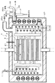
図1、図2において、符号1は固体酸化物形燃料電池(燃料電池モジュール)、符号2は内壁に断熱材27を層状に付装した円筒状のハウジング、符号3は積層方向を縦にして燃料電池モジュール1の中央に配設された燃料電池スタックである。
この燃料電池スタック3は、固体電解質層4の両面に燃料極層5および空気極層(酸化剤極層)6を配した発電セル7と、燃料極層5の外側の燃料極集電体8と、空気極層6の外側の空気極集電体(酸化剤極集電体)9と、各集電体8、9の外側のセパレータ10を順番に積層した構造を有する筒状体で成る。
【0019】
ここで、固体電解質層4はイットリアを添加した安定化ジルコニア(YSZ)等で構成され、燃料極層5はNi、Co等の金属あるいはNi−YSZ、Co−YSZ等のサーメットで構成され、空気極層6はLaMnO3 、LaCoO3 等で構成され、燃料極集電体8はNi基合金等のスポンジ状の多孔質焼結金属板で構成され、空気極集電体9はAg基合金等のスポンジ状の多孔質焼結金属板で構成され、セパレータ10はステンレス等で構成されている。
【0020】
また、燃料電池スタック3の側方には、各セパレータ10の燃料通路26に接続管11を通して燃料ガスを供給する燃料用マニホールド13と、各セパレータ10の酸化剤通路25に接続管12を通して酸化剤ガスとしての空気を供給する酸化剤用マニホールド14とが、発電セル7の積層方向に延在して設けられている。
【0021】
また、マニホールド13、14の外周側には、各マニホールド13、14につながる燃料ガス予熱管15、酸化剤ガス予熱管16や、各予熱管15、16および燃料電池スタック3を予熱するヒータ20等が配設されている。ヒータ20および予熱管15、16は、ハウジング2の内部に収容されており、ハウジング2内の各予熱管15、16に外部の燃料ガス供給管17、酸化剤ガス供給管18がそれぞれ接続されている。
【0022】
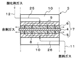
また、この固体酸化物形燃料電池1は、発電セル7の外周部にガス漏れ防止シールを設けないシールレス構造とされており、運転時には、図2に示すように、燃料通路26および酸化剤通路25を通してセパレータ10の略中心部から発電セル7に向けて供給される燃料ガスおよび酸化剤ガス(空気)を、発電セル7の外周方向に拡散させながら燃料極層5および空気極層6の全面に良好な分布で行き渡らせて発電反応を生じさせると共に、発電反応で消費されなかった残余の高温ガスを、発電セル7の外周部から外に自由に放出するようになっている。また、ハウジング2には、その内部空間、即ち、発電反応室21に放出された余剰ガスを燃料電池モジュール1の外に排出するための排気管22a、22bが設けられている。
【0023】
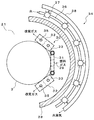
ところで、本実施形態では、図3に示すように、発電反応室21内において、燃料電池スタック3の放射伝熱が可能となる燃料電池スタック3の近傍に炭化水素触媒を充填した燃料改質器30が燃料電池スタック3の高さ方向に配設されている。この燃料改質器30は、未改質の燃料ガスが導入される中央部の箱形第1改質器31と、第1改質器31の両側に配置される一対の箱形第2改質器32とで構成されており、燃料電池スタック3からの放射熱を効率良く受熱できるよう、これらの改質器31、32が燃料電池スタック3の円周に沿って円弧状に配置されている。
そして、第1改質器31と左右の第2改質器32とは、それぞれ配管33によって接続されており、第1改質器31に導入された未改質の燃料ガスが第1改質器31を通過後、この配管33を通して両側の第2改質器32、32に導入されるようになっている。尚、第1改質器31のガス導入口39は図示しない配管により燃料ガス予熱管15に接続されていると共に、第2改質器32、32の出口35、35は、図示しない配管により燃料用マニホールド13に接続されている(図1参照)。
【0024】
この燃料改質器30に対応してその外側(ハウジング2側)に、改質用の高温水蒸気を得るための水気化器34が配設されており、且つ、この水気化器34と燃料改質器30の間に断熱材等で成る熱遮蔽部材28が燃料電池スタック3を囲むように配設されて燃料改質機構を構成している。
【0025】
本実施形態において、水気化器34は、中央の燃料電池スタック3を取り囲むように所定の間隔を持って配設された高さ方向に延びる複数のフィン付き垂直管37で構成されている。そして、各々垂直管37の下端部は管部材36により連結されており、図1の水供給管19を通して供給される水蒸気発生用の水は当管部材36を通して各垂直管37に導入され、垂直管37内において熱交換されて高温水蒸気を発生する。高温水蒸気は各垂直管37の上端部より管部材38より燃料改質器30に導入されるようになっている。
【0026】
尚、水気化器34の構造は上記した垂直管37に限るものではなく、燃料電池スタック3を取り囲む熱遮蔽部材28の周囲に給水管を螺旋状に配管した蛇管構造としても良い。何れにしても、水気化器34は発電反応室21内において、燃料電池スタック3からの排熱を熱エネルギー源として高温水蒸気を発生し、未改質の燃料ガスと混合されて第1改質器31に導入されるように構成されている。
【0027】
燃料改質には、改質反応のための高温(650〜800℃)が必要であり、一方、改質用の高温水蒸気を得るには改質反応のような高温は必要なく、寧ろ多量の熱量を必要とする。因みに、水気化器34の周囲温度は300℃程度確保できていれば水蒸気の発生は十分である。
【0028】
本構成において、燃料改質器30は、熱遮蔽部材28による保温効果で得られる高温雰囲気中で燃料電池スタック3からの放射熱を効率良く受熱し、十分な改質を行うことができると共に、水気化器34は熱遮蔽部材28より伝導される熱や、熱遮断部材を越えて誘導される排気熱により、多量の熱量を吸収して効率的に高温水蒸気を発生することが可能となる。
また、熱遮蔽部材28を設けて燃料改質器30と水気化器34を熱的に隔離すことにより、水気化器34の気化作用(熱交換)による熱吸収で改質器30側が冷却されることが防止でき、燃料改質器30の周りに十分な改質反応が行える高温雰囲気状態を確保することができる。このように、燃料電池からの排熱を有効に利用した高効率発電システムを実現できる。
【0029】
次に、本実施形態の燃料改質機構の動作を説明する。
燃料電池の運転時には燃料ガスである炭化水素ガス(CH4 )と水気化器34からの高温水蒸気の混合ガスがガス導入口39より第1改質器31に導入される。尚、図1においては、燃料ガス予熱管15から予熱された燃料ガスが供給される。この混合ガスは第1改質器31より第2改質器32に誘導され、改質器内を流通する過程で炭化水素触媒に接触して水蒸気改質法による炭化水素ガスの改質反応が行われる。この改質反応は吸熱反応であって、改質反応に必要な高熱(例えば、650〜800℃)は、燃料電池スタック3からの放射熱を受熱して得られる。燃料改質器30は燃料電池スタック3の周囲方向の放射伝熱可能な好適位置に配置されているので、改質反応の吸熱反応に必要とされる十分な高熱を直接受熱することができる。
【0030】
第1改質器3で改質された燃料ガスは左右の出口より配管33、33を通して第2改質器32、32に導入され、第2改質器32内を流通する過程で炭化水素触媒に接触してさらに改質される。第2改質器32の改質反応で得られた水素リッチな改質ガス(H2 、CO、CO2 )は、第2改質器32の出口35、35より図示しない配管を通して図1に示す燃料用マニホールド13に誘導され、ここから各接続管11を通して各セパレータ10の側部に導入される。図2に示すように、改質ガスはさらにセパレータ10の側面から燃料通路26を通して燃料極側に吐出し、燃料極集電体8内を拡散移動して燃料極層5に達し、発電反応が行われる。
【0031】
以上、本実施形態では、ジルコニア等の固体酸化物を電解質とする固体酸化物形燃料電池(SOFC)について説明したが、これに限るものではなく、燐酸を電解質とする燐酸形燃料電池(PAFC)、溶融炭酸塩を電解質とする溶融炭酸塩形燃料電池(MCFC)、或いは、イオン交換膜を電解質とする固体高分子形燃料電池(PEFC)等についても勿論適用可能である。
【0032】
【発明の効果】
以上説明したように、本発明によれば、燃料改質器では、熱遮蔽部材による保温効果で得られる高温雰囲気中で燃料電池スタックからの放射熱を効率良く受熱し、十分な改質温度にて好適な燃料改質が行われると共に、水気化器では、熱遮断部材からの伝導熱や排気熱より多量の熱量を吸収して効率的に高温水蒸気を発生することができる。
このように、従来余剰エネルギーとして外部に放出されていた熱を有効に利用することができ、発電システムの効率化が図れる。
【図面の簡単な説明】
【図1】本発明が適用された固体酸化物形燃料電池の内部構成を示す断面図。
【図2】燃料電池スタックの要部概略構成図で、運転時のガスの流れを示す。
【図3】燃料改質機構の要部概略構成を示す上面図。
【符号の説明】
1 燃料電池(固体酸化物形燃料電池)
2 ハウジング
3 燃料電池スタック
7 発電セル
10 セパレータ
28 熱遮蔽部材
30 燃料改質器
34 水気化器[0001]
BACKGROUND OF THE INVENTION
The present invention relates to an internal reforming fuel cell, and more particularly to a fuel cell that can efficiently reform fuel gas by efficiently using exhaust heat of a fuel cell stack.
[0002]
[Prior art]
Solid oxide fuel cells are being developed as third-generation fuel cells for power generation. At present, three types of solid oxide fuel cells have been proposed: a cylindrical type, a monolith type, and a flat plate type, all of which include a solid electrolyte composed of an oxide ion conductor formed by an air electrode layer and a fuel electrode layer. It has a laminated structure sandwiched between them. A fuel cell stack is configured by alternately laminating power generation cells and separators made of this laminate.
[0003]
The power generation cell is supplied with oxygen (air) as an oxidant gas on the air electrode side and fuel gas (H 2 , CO, CH 4, etc.) on the fuel electrode side. The air electrode and the fuel electrode are both porous so that the gas can reach the interface with the solid electrolyte. Oxygen supplied to the air electrode side passes through the pores in the air electrode layer and reaches the vicinity of the interface with the solid electrolyte layer. At this part, it receives electrons from the air electrode and converts them into oxide ions (O 2− ). Ionized. The oxide ions diffuse and move in the solid electrolyte layer toward the fuel electrode. Oxide ions that have reached the vicinity of the interface with the fuel electrode react with the fuel gas at this portion to generate reaction products (H 2 O, CO 2, etc.), and emit electrons to the fuel electrode.
[0004]
The electrode reaction when hydrogen is used as the fuel is as follows.
Air electrode: 1/2 O 2 + 2e − → O 2−
Fuel electrode: H 2 + O 2− → H 2 O + 2e −
Overall: H 2 +1/2 O 2 → H 2 O
[0005]
By the way, since the fuel gas used in the fuel cell is a hydrocarbon compound (referred to as raw fuel) such as natural gas (methane gas), the raw fuel is actually reformed into a fuel gas mainly composed of hydrogen. Need to use. As a reforming method, when the raw fuel is a hydrocarbon-based gas fuel or liquid fuel, a steam reforming method is usually used.
[0006]
For example, a reforming reaction using methane gas as a raw fuel is as follows.
The desulfurized methane gas is added with water vapor in the reformer to become hydrogen and carbon monoxide. This reforming reaction is an endothermic reaction, and the temperature is as high as 650 to 800 ° C.
CH 4 + H 2 O → 3H 2 + CO
At this time, the generated carbon monoxide further reacts with water vapor and changes into hydrogen and carbon dioxide.
CO + H 2 O → H 2 + CO 2
[0007]
Conventionally, reforming methods for fuel cells include an external reforming method in which a reformer is installed outside the fuel cell, and an internal reforming method in which a fuel reforming mechanism is directly incorporated inside a high-temperature fuel cell stack. It has been. Since the steam reforming reaction is an endothermic reaction, the external reforming method that requires the supply of heat for the reforming reaction is not suitable for the fuel reforming mechanism of the fuel cell due to its poor power generation efficiency. An efficient internal reforming method that can utilize part of the heat generated from the fuel cell for the endothermic reaction of the reforming reaction has attracted attention.
As described above, the reforming reaction is an endothermic reaction, and the reforming catalyst needs to be heated to at least 640 ° C. or more, preferably 700 ° C. or more in order to perform a sufficient reforming reaction. In the fuel cell of the type, high-temperature exhaust heat from the fuel cell stack is used as thermal energy for reforming.
[0008]
[0009]
[Patent Document 1]
Japanese Patent Laid-Open No. Sho 62-283570 [0010]
[Problems to be solved by the invention]
By the way, taking a solid oxide fuel cell as an example, a high-temperature solid oxide fuel cell having an operating temperature of around 1000 ° C. has a large amount of discharged thermal energy, and thus recovers the thermal energy required for reforming. However, in the case of a low-temperature operation type solid oxide fuel cell with an operating temperature of around 700 ° C., the amount of heat energy discharged is smaller than that of the previous high-temperature type, and the thermal space is relaxed. Therefore, the reforming reaction may become insufficient unless efficient heat recovery is performed. If the reforming is insufficient, the battery performance will drop sharply due to carbon deposition from methane (unreformed gas), or if methane is introduced into the power generation cell, the fuel electrode will peel off due to thermal stress due to endothermic reaction. This causes the negative effect of shortening the service life.
[0011]
Therefore, in order to obtain the stable power generation performance without the above-mentioned adverse effects, it is a big issue how to efficiently recover the surplus energy (exhaust heat) discharged from the fuel cell and effectively use it for the power generation reaction. Yes.
[0012]
The present invention has been made in view of such a conventional problem, and an object of the present invention is to provide a fuel cell capable of performing suitable reforming by efficiently using exhaust heat from the fuel cell stack.
[0013]
[Means for Solving the Problems]
That is, according to the first aspect of the present invention, a fuel cell stack is configured by alternately stacking power generation cells and separators, and is housed in a housing, and a reaction gas is supplied into the fuel cell stack during operation. In an internal reforming fuel cell that generates a power generation reaction, a fuel reformer is disposed around the fuel cell stack, and reforming steam is obtained on the housing side outside the fuel reformer. A water vaporizer is provided, and a heat shielding member is provided between the fuel reformer and the water vaporizer.
[0015]
In the housing, it is necessary to supply a high temperature for the reforming reaction (endothermic reaction) for fuel reforming. On the other hand, in order to obtain high-temperature steam for reforming, a larger amount than the high temperature is required as in the reforming reaction. It is necessary to supply the amount of heat.
Therefore, in the present invention, the fuel reformer is disposed around the fuel cell stack that can directly receive the radiant heat from the fuel cell stack, and the water vaporizer is disposed on the outer side (direction closer to the housing) with the heat shielding member interposed therebetween. The fuel reformer and the water vaporizer are thermally isolated from each other. The reformer is in a high-temperature atmosphere obtained by the heat insulation effect by the heat shielding member, can efficiently receive the radiant heat and perform sufficient reforming, and the water vaporizer is the conduction heat of the heat shielding member. In addition, a large amount of heat is absorbed by the exhaust heat induced beyond the heat blocking member to generate high-temperature steam. As a result, a highly efficient power generation system that effectively uses exhaust heat from the fuel cell can be realized.
[0016]
DETAILED DESCRIPTION OF THE INVENTION
Hereinafter, embodiments of the present invention will be described with reference to FIGS.
[0017]
1 shows an internal configuration of a solid oxide fuel cell to which the present invention is applied, FIG. 2 shows a schematic configuration of a main part of a fuel cell stack, and FIG. 3 shows a schematic configuration of a fuel reforming mechanism in a power generation reaction chamber. Show.
[0018]
First, the configuration of the solid oxide fuel cell will be described with reference to FIG.
1 and 2,
The
[0019]
Here, the
[0020]
Further, on the side of the
[0021]
Further, on the outer peripheral side of the
[0022]
Further, the solid
[0023]
By the way, in this embodiment, as shown in FIG. 3, in the power
The
[0024]
A
[0025]
In the present embodiment, the
[0026]
Note that the structure of the
[0027]
Fuel reforming requires a high temperature (650-800 ° C.) for the reforming reaction, while high temperature steam for reforming is not required to obtain a high-temperature steam for reforming. Requires heat. Incidentally, the generation of water vapor is sufficient if the ambient temperature of the
[0028]
In this configuration, the fuel reformer 30 can efficiently receive the radiant heat from the
Further, by providing the
[0029]
Next, the operation of the fuel reforming mechanism of this embodiment will be described.
During operation of the fuel cell, a mixed gas of hydrocarbon gas (CH 4 ), which is a fuel gas, and high-temperature steam from the
[0030]
The fuel gas reformed by the
[0031]
As described above, in the present embodiment, the solid oxide fuel cell (SOFC) using a solid oxide such as zirconia as an electrolyte has been described. However, the present invention is not limited to this, and the phosphoric acid fuel cell (PAFC) using phosphoric acid as an electrolyte. Of course, the present invention can also be applied to a molten carbonate fuel cell (MCFC) using molten carbonate as an electrolyte, or a polymer electrolyte fuel cell (PEFC) using an ion exchange membrane as an electrolyte.
[0032]
【The invention's effect】
As described above, according to the present invention, the fuel reformer efficiently receives the radiant heat from the fuel cell stack in a high temperature atmosphere obtained by the heat insulation effect by the heat shielding member, and achieves a sufficient reforming temperature. In addition, the fuel vaporizer can efficiently generate high-temperature steam by absorbing a larger amount of heat than the conduction heat from the heat blocking member and the exhaust heat.
Thus, the heat that has been released to the outside as surplus energy in the past can be used effectively, and the efficiency of the power generation system can be improved.
[Brief description of the drawings]
FIG. 1 is a cross-sectional view showing an internal configuration of a solid oxide fuel cell to which the present invention is applied.
FIG. 2 is a schematic configuration diagram of a main part of a fuel cell stack, showing a gas flow during operation.
FIG. 3 is a top view showing a schematic configuration of a main part of a fuel reforming mechanism.
[Explanation of symbols]
1 Fuel cell (solid oxide fuel cell)
2
Claims (1)
前記燃料電池スタックの周辺に燃料改質器を配設し、この燃料改質器の外側である前記ハウジング側に改質用水蒸気を得る水気化器を設けると共に、前記燃料改質器と前記水気化器との間に熱遮蔽部材を設けたことを特徴とする燃料電池。A fuel cell stack is formed by alternately stacking power generation cells and separators, and is housed in a housing, and an internal reforming fuel that generates a power generation reaction by supplying a reaction gas into the fuel cell stack during operation. In batteries,
A fuel reformer is disposed around the fuel cell stack, a water vaporizer for obtaining reforming steam is provided on the housing side outside the fuel reformer, and the fuel reformer and the water vapor are provided. A fuel cell, wherein a heat shielding member is provided between the fuel cell and the fuel cell.
Priority Applications (1)
| Application Number | Priority Date | Filing Date | Title |
|---|---|---|---|
| JP2003178852A JP4501367B2 (en) | 2003-06-24 | 2003-06-24 | Fuel cell |
Applications Claiming Priority (1)
| Application Number | Priority Date | Filing Date | Title |
|---|---|---|---|
| JP2003178852A JP4501367B2 (en) | 2003-06-24 | 2003-06-24 | Fuel cell |
Publications (2)
| Publication Number | Publication Date |
|---|---|
| JP2005019036A JP2005019036A (en) | 2005-01-20 |
| JP4501367B2 true JP4501367B2 (en) | 2010-07-14 |
Family
ID=34180314
Family Applications (1)
| Application Number | Title | Priority Date | Filing Date |
|---|---|---|---|
| JP2003178852A Expired - Fee Related JP4501367B2 (en) | 2003-06-24 | 2003-06-24 | Fuel cell |
Country Status (1)
| Country | Link |
|---|---|
| JP (1) | JP4501367B2 (en) |
Families Citing this family (11)
| Publication number | Priority date | Publication date | Assignee | Title |
|---|---|---|---|---|
| JP4906249B2 (en) * | 2004-06-30 | 2012-03-28 | 京セラ株式会社 | Fuel cell reformer |
| JP2007128717A (en) * | 2005-11-02 | 2007-05-24 | Mitsubishi Materials Corp | Operation method of fuel cell |
| US20110076573A1 (en) * | 2005-02-22 | 2011-03-31 | Jun Akikusa | Solid Oxide Type Fuel Cell and Operating Method Thereof |
| JP5098134B2 (en) * | 2005-05-02 | 2012-12-12 | ダイキン工業株式会社 | Solid oxide fuel cell |
| JP2007220575A (en) * | 2006-02-20 | 2007-08-30 | Mitsubishi Materials Corp | Fuel cell power generation device, control program, and control method |
| WO2008131078A1 (en) * | 2007-04-17 | 2008-10-30 | Modine Manufacaturing Company | Solid oxide fuel cell unit for use in distributed power generation |
| US8409758B2 (en) | 2007-04-17 | 2013-04-02 | Modine Manufacturing Company | Fuel cell system with partial external reforming and direct internal reforming |
| JP5606165B2 (en) * | 2010-06-08 | 2014-10-15 | 京セラ株式会社 | Cell stack device, fuel cell module and fuel cell device |
| WO2012132635A1 (en) * | 2011-03-31 | 2012-10-04 | 株式会社村田製作所 | Fuel cell module |
| US9947951B2 (en) | 2013-02-25 | 2018-04-17 | Sumitomo Precision Products Co., Ltd. | Fuel cell module |
| CN113381049B (en) * | 2021-06-09 | 2022-04-12 | 广东石油化工学院 | SOFC cell stack of button type fuel cell integrated fuel reformer |
Citations (7)
| Publication number | Priority date | Publication date | Assignee | Title |
|---|---|---|---|---|
| JPH11322302A (en) * | 1999-01-08 | 1999-11-24 | Sanyo Electric Co Ltd | Reformer for fuel cell |
| JP2001266924A (en) * | 2000-03-24 | 2001-09-28 | Tokyo Gas Co Ltd | Solid electrolyte fuel cell system |
| JP2002151127A (en) * | 2000-11-16 | 2002-05-24 | Ngk Insulators Ltd | Cogeneration power plant |
| JP2002201478A (en) * | 2000-12-28 | 2002-07-19 | Idemitsu Kosan Co Ltd | Method for desulfurizing and reforming kerosine |
| JP2002358997A (en) * | 2001-05-31 | 2002-12-13 | Nippon Telegr & Teleph Corp <Ntt> | Solid oxide fuel cell stack |
| JP2003123824A (en) * | 2001-10-16 | 2003-04-25 | Shin Etsu Chem Co Ltd | Fuel cell system |
| JP2003282113A (en) * | 2002-03-26 | 2003-10-03 | Toto Ltd | Solid oxide fuel cell system |
-
2003
- 2003-06-24 JP JP2003178852A patent/JP4501367B2/en not_active Expired - Fee Related
Patent Citations (7)
| Publication number | Priority date | Publication date | Assignee | Title |
|---|---|---|---|---|
| JPH11322302A (en) * | 1999-01-08 | 1999-11-24 | Sanyo Electric Co Ltd | Reformer for fuel cell |
| JP2001266924A (en) * | 2000-03-24 | 2001-09-28 | Tokyo Gas Co Ltd | Solid electrolyte fuel cell system |
| JP2002151127A (en) * | 2000-11-16 | 2002-05-24 | Ngk Insulators Ltd | Cogeneration power plant |
| JP2002201478A (en) * | 2000-12-28 | 2002-07-19 | Idemitsu Kosan Co Ltd | Method for desulfurizing and reforming kerosine |
| JP2002358997A (en) * | 2001-05-31 | 2002-12-13 | Nippon Telegr & Teleph Corp <Ntt> | Solid oxide fuel cell stack |
| JP2003123824A (en) * | 2001-10-16 | 2003-04-25 | Shin Etsu Chem Co Ltd | Fuel cell system |
| JP2003282113A (en) * | 2002-03-26 | 2003-10-03 | Toto Ltd | Solid oxide fuel cell system |
Also Published As
| Publication number | Publication date |
|---|---|
| JP2005019036A (en) | 2005-01-20 |
Similar Documents
| Publication | Publication Date | Title |
|---|---|---|
| JP5061450B2 (en) | Fuel cell | |
| US8021794B2 (en) | Fuel cell with cross-shaped reformer | |
| JP2005243647A (en) | Reformer of fuel cell system and fuel cell system using the same | |
| JP4956946B2 (en) | Fuel cell | |
| KR20080000674A (en) | Fuel cell system | |
| JP4501367B2 (en) | Fuel cell | |
| JP3539562B2 (en) | Solid oxide fuel cell stack | |
| JP4797352B2 (en) | Solid oxide fuel cell | |
| JP4706190B2 (en) | Solid oxide fuel cell | |
| JP4513282B2 (en) | Fuel cell | |
| JP2004362800A (en) | Fuel cell | |
| JP2007080761A (en) | Fuel cell and its starting method | |
| JP4544055B2 (en) | Fuel cell | |
| JP5307376B2 (en) | Fuel reforming fuel cell | |
| JP4461955B2 (en) | Solid oxide fuel cell | |
| JP2007005134A (en) | Steam generator and fuel cell | |
| JP2005019034A (en) | Solid oxide fuel cell | |
| JP2009245627A (en) | Solid oxide fuel cell | |
| JP4696495B2 (en) | Fuel cell power generator | |
| JP5077384B2 (en) | Fuel cell | |
| JP4706191B2 (en) | Solid oxide fuel cell | |
| JP4849201B2 (en) | Solid oxide fuel cell | |
| JP2010238440A (en) | Fuel battery module | |
| JP6187209B2 (en) | Fuel cell device | |
| JP2011159443A (en) | Fuel-cell module |
Legal Events
| Date | Code | Title | Description |
|---|---|---|---|
| A621 | Written request for application examination |
Free format text: JAPANESE INTERMEDIATE CODE: A621 Effective date: 20060623 |
|
| A131 | Notification of reasons for refusal |
Free format text: JAPANESE INTERMEDIATE CODE: A131 Effective date: 20100112 |
|
| A521 | Written amendment |
Free format text: JAPANESE INTERMEDIATE CODE: A523 Effective date: 20100305 |
|
| TRDD | Decision of grant or rejection written | ||
| A01 | Written decision to grant a patent or to grant a registration (utility model) |
Free format text: JAPANESE INTERMEDIATE CODE: A01 Effective date: 20100330 |
|
| A01 | Written decision to grant a patent or to grant a registration (utility model) |
Free format text: JAPANESE INTERMEDIATE CODE: A01 |
|
| A61 | First payment of annual fees (during grant procedure) |
Free format text: JAPANESE INTERMEDIATE CODE: A61 Effective date: 20100412 |
|
| R150 | Certificate of patent or registration of utility model |
Free format text: JAPANESE INTERMEDIATE CODE: R150 |
|
| FPAY | Renewal fee payment (event date is renewal date of database) |
Free format text: PAYMENT UNTIL: 20130430 Year of fee payment: 3 |
|
| LAPS | Cancellation because of no payment of annual fees |