EP1953598A1 - Fixing device and fixing method - Google Patents
Fixing device and fixing method Download PDFInfo
- Publication number
- EP1953598A1 EP1953598A1 EP08001261A EP08001261A EP1953598A1 EP 1953598 A1 EP1953598 A1 EP 1953598A1 EP 08001261 A EP08001261 A EP 08001261A EP 08001261 A EP08001261 A EP 08001261A EP 1953598 A1 EP1953598 A1 EP 1953598A1
- Authority
- EP
- European Patent Office
- Prior art keywords
- sheet
- air
- fixing
- fixing unit
- unit
- Prior art date
- Legal status (The legal status is an assumption and is not a legal conclusion. Google has not performed a legal analysis and makes no representation as to the accuracy of the status listed.)
- Withdrawn
Links
- 238000000034 method Methods 0.000 title claims description 14
- 230000002265 prevention Effects 0.000 claims abstract description 35
- 239000011521 glass Substances 0.000 claims description 9
- 230000001681 protective effect Effects 0.000 claims description 9
- 239000006059 cover glass Substances 0.000 abstract description 13
- 238000001514 detection method Methods 0.000 description 7
- 239000002131 composite material Substances 0.000 description 6
- 238000010521 absorption reaction Methods 0.000 description 3
- 230000000149 penetrating effect Effects 0.000 description 3
- 230000002093 peripheral effect Effects 0.000 description 3
- 239000000843 powder Substances 0.000 description 3
- 238000007599 discharging Methods 0.000 description 2
- 230000001678 irradiating effect Effects 0.000 description 2
- 238000012986 modification Methods 0.000 description 2
- 230000004048 modification Effects 0.000 description 2
- 230000003287 optical effect Effects 0.000 description 2
- 239000000853 adhesive Substances 0.000 description 1
- 230000001070 adhesive effect Effects 0.000 description 1
- 239000003086 colorant Substances 0.000 description 1
- 238000011109 contamination Methods 0.000 description 1
- 238000010586 diagram Methods 0.000 description 1
- 239000000428 dust Substances 0.000 description 1
- 229910052724 xenon Inorganic materials 0.000 description 1
- FHNFHKCVQCLJFQ-UHFFFAOYSA-N xenon atom Chemical compound [Xe] FHNFHKCVQCLJFQ-UHFFFAOYSA-N 0.000 description 1
Images




Classifications
-
- G—PHYSICS
- G03—PHOTOGRAPHY; CINEMATOGRAPHY; ANALOGOUS TECHNIQUES USING WAVES OTHER THAN OPTICAL WAVES; ELECTROGRAPHY; HOLOGRAPHY
- G03G—ELECTROGRAPHY; ELECTROPHOTOGRAPHY; MAGNETOGRAPHY
- G03G15/00—Apparatus for electrographic processes using a charge pattern
- G03G15/20—Apparatus for electrographic processes using a charge pattern for fixing, e.g. by using heat
- G03G15/2003—Apparatus for electrographic processes using a charge pattern for fixing, e.g. by using heat using heat
- G03G15/2007—Apparatus for electrographic processes using a charge pattern for fixing, e.g. by using heat using heat using radiant heat, e.g. infrared lamps, microwave heaters
- G03G15/201—Apparatus for electrographic processes using a charge pattern for fixing, e.g. by using heat using heat using radiant heat, e.g. infrared lamps, microwave heaters of high intensity and short duration, i.e. flash fusing
-
- G—PHYSICS
- G03—PHOTOGRAPHY; CINEMATOGRAPHY; ANALOGOUS TECHNIQUES USING WAVES OTHER THAN OPTICAL WAVES; ELECTROGRAPHY; HOLOGRAPHY
- G03G—ELECTROGRAPHY; ELECTROPHOTOGRAPHY; MAGNETOGRAPHY
- G03G15/00—Apparatus for electrographic processes using a charge pattern
- G03G15/65—Apparatus which relate to the handling of copy material
- G03G15/6555—Handling of sheet copy material taking place in a specific part of the copy material feeding path
- G03G15/657—Feeding path after the transfer point and up to the fixing point, e.g. guides and feeding means for handling copy material carrying an unfused toner image
-
- G—PHYSICS
- G03—PHOTOGRAPHY; CINEMATOGRAPHY; ANALOGOUS TECHNIQUES USING WAVES OTHER THAN OPTICAL WAVES; ELECTROGRAPHY; HOLOGRAPHY
- G03G—ELECTROGRAPHY; ELECTROPHOTOGRAPHY; MAGNETOGRAPHY
- G03G2215/00—Apparatus for electrophotographic processes
- G03G2215/00362—Apparatus for electrophotographic processes relating to the copy medium handling
- G03G2215/00367—The feeding path segment where particular handling of the copy medium occurs, segments being adjacent and non-overlapping. Each segment is identified by the most downstream point in the segment, so that for instance the segment labelled "Fixing device" is referring to the path between the "Transfer device" and the "Fixing device"
- G03G2215/00413—Fixing device
-
- G—PHYSICS
- G03—PHOTOGRAPHY; CINEMATOGRAPHY; ANALOGOUS TECHNIQUES USING WAVES OTHER THAN OPTICAL WAVES; ELECTROGRAPHY; HOLOGRAPHY
- G03G—ELECTROGRAPHY; ELECTROPHOTOGRAPHY; MAGNETOGRAPHY
- G03G2215/00—Apparatus for electrophotographic processes
- G03G2215/00362—Apparatus for electrophotographic processes relating to the copy medium handling
- G03G2215/00535—Stable handling of copy medium
- G03G2215/00649—Electrodes close to the copy feeding path
Definitions
- the present invention relates to a fixing device and fixing method.
- an image forming device of an electrophotographic method there is an image forming device using a flash fixing method for fixing a toner on a recording media by using a flash lump.
- Such a device is described as irradiating the recording media with a flash light through a protective glass, as disclosed in Japanese Patent Application Laid-Open ( JP-A) No. 2002-229418 , for example.
- a fan is provided between a developing unit and a fixing unit.
- a fixing device of a first aspect of the present invention has a fixing unit provided with a heat source for fixing a toner image on sheet in a state out of contact with the sheet, and a contact prevention unit preventing contact of the fixing unit and the sheet.
- the sheet does not contact the fixing unit by the contact prevention unit, so that paper powder and a toner on the sheet do not adhere to a surface of the fixing unit.
- the contact prevention unit may have an air sending part sending air in a direction from the fixing unit toward the sheet and keeping the sheet away from the fixing unit.
- the sheet may be kept away from the fixing unit by sending air to the sheet.
- the contact prevention unit may have an air intake part arranged at a position opposed to the fixing unit and intaking air to keep the sheet away from the fixing unit.
- the sheet since the sheet is drawn from a rear surface side of the sheet having toner image on its front surface by the air intake part, the sheet may be kept away from the fixing unit.
- the contact prevention unit may have an air sending part sending air in a direction from the fixing unit to the sheet and an air intake part arranged at a position opposed to the fixing unit and intaking air, and the contact prevention unit keeps the sheet away from the fixing unit by using the air sending part and the air intake part.
- the sheet since air is sent to the surface of the sheet and air is intaken from the rear surface of the sheet, the sheet may be kept away from the fixing unit.
- the contact prevention unit may have an electrostatic force generation part arranged at a position opposed to the fixing unit and keeping the sheet away from the fixing unit by electrostatic attracting force.
- the sheet may be kept away from the fixing unit by the electrostatic attracting force.
- the fixing device may further has a reverse air sending part arranged at a position opposed to the fixing unit and sending air in a direction from the sheet toward the fixing unit to put the sheet close to the fixing unit, during fixing, air is sent to the sheet by the reverse air sending part and during non-fixing, the operation of the reverse air sending part is stopped and air is sent to the sheet by the air sending part.
- a reverse air sending part arranged at a position opposed to the fixing unit and sending air in a direction from the sheet toward the fixing unit to put the sheet close to the fixing unit, during fixing, air is sent to the sheet by the reverse air sending part and during non-fixing, the operation of the reverse air sending part is stopped and air is sent to the sheet by the air sending part.
- the sheet gets close to the fixing unit when fixing, fixation of the toner image on the sheet becomes better.
- the sheet may be kept away from the fixing unit.
- the fixing unit may be provided with the heat source and a protective glass for shielding the heat source, and the contact prevention unit may prevent contact of the sheet and the protective glass.
- the fixing unit since the fixing unit is provided with the protective glass, the sheet is prevented from directly contacting the heat source.
- the contact prevention unit prevents the sheet and the protective glass from contacting each other, contamination of a surface of the protective glass by sheet powder and toner is prevented.
- the contact prevention unit may have a moving part abutting the sheet to keep the sheet away from the fixing unit.
- the sheet is kept away from the fixing unit with the moving part abutting the sheet.
- a fixing method comprises keeping sheet away from a fixing unit with a contact prevention unit when a sheet jam has occured.
- the sheet does not contact the fixing unit by the contact prevention unit, so that sheet powder and a toner on the sheet do not adhere to a surface of the fixing unit.
- the contact prevention unit may have an air sending part and the air sending part sends air toward the sheet to keep the sheet away from the fixing unit.
- the sheet may be kept away from the fixing unit by sending air to the sheet.
- the contact prevention unit may have an air intake part and the air intake part intakes air to attract the sheet and keep the sheet away from the fixing unit.
- the sheet may be kept away from the fixing unit by the air intake part.
- the contact prevention unit may have an air sending part and an air intake part, and the sheet is kept away from the fixing unit by sending air to one surface of the sheet with the air sending part and intaking air to attract the other surface of the sheet with the air intake part.
- the sheet since air is sent to the one surface of the sheet and air is intaken from the other surface of the sheet, the sheet may be kept away from the fixing unit.
- the sheet may be moved close to the fixing unit with a reverse air sending part when a sheet jam does not occur; and operation of the reverse air sending part may be stopped when a sheet jam occurs.
- the sheet gets close to the fixing unit when sheet jam does not occur, fixation of the toner image on the sheet becomes better.
- the sheet can be kept away from the fixing unit.
- the contact prevention unit may have an electrostatic force generation part and the electrostatic force generation part attracts the sheet to keep the sheet away from the fixing unit by electrostatic attracting force.
- the sheet may be kept away from the fixing unit by the electrostatic attracting force.
- the contact prevention unit may have a moving part and the moving part abuts the sheet to keep the sheet away from the fixing unit.
- the sheet is kept away from the fixing unit with the moving part abutting the sheet.
- an image forming device 100 for performing flash fixing for fixing by an irradiation heat of a xenon lump or the like after forming an image is provided.
- the image forming device 100 forms the image on recording paper 112, formed of continuous form paper capable of being cut, as one example of the paper.
- the recording paper 112 inserted into the image forming device 100 from an arrow IN direction is wrapped around wrapping rollers 114 and 116, and is fed on a feeding path formed so as to cross an inner portion of the image forming device 100 at a constant speed.
- image forming units 118A, 118B, 118C and 118D for forming toner images of C (cyan), M (magenta), Y (yellow) and K (black), respectively, are arranged along the feeding path at substantially regular intervals therebetween.
- Each of the image forming units 118A to 118D is provided with a photosensitive drum 120, which has the same configuration except the color of the toner image to be formed, and is arranged such that an axis line thereof is orthogonal to a feeding direction of the recording paper 112.
- a charger 122 for charging the photosensitive drum 120 is provided around the photosensitive drum 120.
- An exposure device 124 for irradiating a charged photosensitive drum 120 with an LED light to form an electrostatic latent image is provided on a downstream side of the charger 122 in a rotation direction of the photosensitive drum 120.
- a developing device 126 for forming the toner image by supplying a toner of a predetermined color to the electrostatic latent image on the photosensitive drum 120 is provided on a downstream side of the exposure device 124.
- a transferring device 128 arranged so as to be opposed to the photosensitive drum 120 with the feeding path of the recording paper 112 interposed therebetween for transferring the toner image on the recording paper 112 is provided on a downstream side of the developing device 126.
- a discharger 130 for discharging a surface of the photosensitive drum 120, a cleaner blade 132 for removing residual toner on the surface of the photosensitive drum 120, and a cleaner brush 134 are arranged on a downstream side of the transferring device 128.
- the image forming units 118A to 118D form the toner images of which colors are different to one another on the peripheral surfaces of the photosensitive drums 120 by the chargers 122, the exposure devices 124, and the developing devices 126, and thereafter, transfer the toner images on the recording paper 112 by the transferring devices 128.
- the image forming unit 118D for black is driven to form a black toner image on the peripheral surface of the photosensitive drum 120 by the charger 122, the exposure device 124 and the developing device 126, and thereafter, by transferring the toner image on the recording paper 112 by the transferring unit 128, the black toner image is formed on the recording paper 112.
- the feeding direction is changed to a substantially vertical direction by a wrapping roller 138 on a downstream side of positions of the image forming units 118A to 118D.
- the recording paper 112 is fed upward in the substantially vertical direction.
- a fixing device 10 is arranged on the feeding path between the wrapping rollers 138 and 142.
- the fixing device 10 is provided with a flash fixing unit 140 as one example of a fixing unit and an air intake unit 11 as one example of an air intake part.
- a tension roller 144 is provided at a downstream side of the wrapping roller 142.
- Detection part such as a pressure sensor or an optical position sensor not shown is provided on the tension roller 144. Also, a portion of an outer peripheral side surface of the tension roller 144 abuts the recording paper 112, and the tension roller 144 is energized in a direction to press the recording paper 112 to a lower side by using a spring or the like.
- the recording paper 112 is tightened with a predetermined tension, and the tension roller 144 is at a position at which the above-described energizing force and the tension of the recording paper 112 are balanced.
- the wrapping rollers 146 and 148 are sequentially arranged at a downstream side of the tension roller 144, and it is configured that the recording paper 112 on which the toner image is fixed is guided to the wrapping rollers 146 and 148 and is discharged outside of the image forming device 100.
- the fixing device 10 is provided with the flash fixing unit 140 and the air intake unit 11 as described above.
- the flash fixing unit 140 has a housing 12 in a box-shape one planar surface of which is opened, and is provided with flash lumps 14 in the housing 12, as one example of six heat sources emitting the flash light.
- the flash lamps 14 emits the flash light by a voltage supplied from a power supply not shown to fuse a toner T on the recording paper 112 by energy of the flash light, thereby fixing the toner image transferred on the recording paper 112.
- a cover glass 16 is arranged on a front surface side of the flash lamps 14 and the feeding path side of the recording paper 112.
- the cover glass 16 as one example of a protective glass is fixed to the housing 12 by adhesion to prevent intrusion of dust or the like into the flash fixing unit 140, and prevents the recording paper 112 and the flash lamps 14 from contacting each other.
- plural penetrating air-through holes 18, 19, 20 and 21 are formed in the housing 12 so as to enclose the flash lamps 14.
- One end of each of stainless pipes 22 and 24 are connected to the air-through holes 18, 19, 20 and 21, and other end of each of the pipes are connected to a fan 26.
- the fan 26 as one example of an air sending part is driven by power supplied by power supply means not shown to supply air to the pipes 22 and 24.
- the air sending part is formed from the fan 26, the pipes 22 and 24, and the air-through holes 18 to 21.
- the air intake unit 11 is arranged on a position opposed to the front surface of the flash fixing unit 140 with the feeding path of the recording paper 112 interposed therebetween.
- the air intake unit 11 as one example of a contact prevention unit has a side plate 28, a duct 32, an air intake device 34 and a pipe 38.
- the side plate 28 is fixed so as to be apart from the recording paper 112 by a predetermined distance, and plural air intake holes 30 penetrating toward the recording paper 112, are formed therein. Also, the duct 32 is provided on a surface opposite to the recording paper 112 of the side plate 28 so as to cover the air intake holes 30.
- An opening is formed on one end portion of the duct 32, and the air intake device 34 is fixed to the opening by a screw, an adhesive or the like. Also, an inclined surface to make an air flow be stable during air intake is formed in the duct 32.
- the air intake device 34 is provided with a fan 36 rotating by driving means such as a motor or the like not shown inside thereof.
- a pipe 38 for discharging intaken air outside of the image forming device 100 is connected to the air intake device 34.
- the fan 36 rotates and intakes air through the air intake holes 30, and the intaken air is discharged from the duct 32 through the fan 36 to the pipe 38.
- the contact prevention unit of this exemplary embodiment is formed of the air sending part from the fan 26 to the air through holes 18 to 21, and the air intake unit 11.
- a jam detection signal is sent to a driving unit not shown and the driving unit drives the fan 26 and the air intake device 34.
- the fan 26 (refer to Fig. 2 ) and the air intake device 34 are driven by the jam detection signal.
- Air sent from an arrow A direction is blown on a recording surface side of the recording paper 112, and a rear surface side of the recording paper 112 is sucked to a side plate 28 side by the air intaken in an arrow B direction.
- the recording paper 112 is kept away from the cover glass 16 of the flash fixing unit 140.
- each of stainless pipes 46 and 48 are connected to the air-through holes 18 and 20 of the flash fixing unit 140, respectively, and the pipes 46 and 48 are connected to a pipe 44 by a three-way joint not shown and inner sides thereof are communicated to one another.
- the other end of the pipe 44 is connected to a first fan 42.
- the first fan 42 is driven by the power supplied from power supplying unit not shown, and supplies air to the pipe 44.
- an air sending unit 40 is arranged on a position opposed to the front surface of the flash fixing unit 140 with the feeding path of the recording paper 112 interposed therebetween.
- the air sending unit 40 as one example of a reverse air sending part has a side plate 50 seperated from the recording paper 112 with a predetermined distance therebetween, a pipe 54, and a second fan 58.
- a plurality of air-through holes 52 penetrating toward the recording paper 112 are formed in the side plate 50.
- a plurality of pipes 54 are arranged on a surface opposite to the recording paper 112 on the side plate 50, and the air-through holes 52 and the pipes 54 are connected and fixed.
- the other end of the pipe 54 is connected to one pipe 56 by a joint not shown, and the other end of the pipe 56 is connected to a second fan 58.
- the second fan 58 is driven by the power supplied from power supplying unit not shown to supply air to the pipe 56.
- the second fan 58 is driven during fixation on the recording paper 112. Air supplied from the second fan 58 is sent through the pipes 56 and 54 in the arrow C direction.
- the recording paper 112 gets close to a flash fixing unit 140 side by air sent from the arrow C direction, and heat by light emission of the flash lumps 14 is transmitted to the toner T on the recording paper 112.
- the jam detection device in the above-described tension roller 144 activates to drive the first fan 42. Air sent from the first fan 42 is sent from the pipe 44 through the pipe 46 or 48 in the arrow D direction.
- a flash fixing unit 70 is provided in the image forming device 100.
- flash lumps 74 as one example of six heat sources are arranged in a housing 72 in a box-shape having an opening on one side, and the opening is covered with the cover glass 76.
- An electrostatic absorption device 60 is arranged at a position opposed to the cover glass 76 with a predetermined distance therebetween.
- the electrostatic absorption device 60 as one example of electrostatic force generation part is configured such that a plastic composite plate 62 in which an electrode not shown is included is arranged on a base 64 for fixed positioning.
- One end of a cable 66 for supplying direct current voltage is connected to the electrode in the plastic composite plate 62.
- the other end of the cable 66 is connected to a power supply 68 for outputting the direct current voltage.
- a charged polar character of the toner T in this exemplary embodiment is set to positive.
- the direct current voltage is not output from the power supply 68 to the electrode inside the plastic composite plate 62, and the recording paper 112 passes between the flash fixing unit 70 and the electrostatic absorption device 60 without being absorbed.
- the jam detection device in the above-described tension roller 144 activates to drive the power supply 68.
- the direct current voltage is supplied to the electrode in the plastic composite plate 62, and a surface of the plastic composite plate 62 charges negatively.
- the polar character of the toner T after transferring is positive, and the polar character on a surface side of the recording paper 112, which contacts the toner T, is negative.
- the polar character of the rear surface side of the recording paper 112, which does not contact the toner T, is positive.
- the recording paper 112 is drawn in an arrow E direction by a Coulomb attraction between a negative charge on the surface of the plastic composite plate 62 and a positive charge on the rear surface side of the recording paper 112.
- the recording paper 112 is kept apart from the cover glass 76.
- a flash fixing unit 90 is provided inside the image forming device 100 (refer to Fig. 1 ).
- flash lumps 92 as one example of six heat sources are arranged in a housing 91 in a box-shape having an opening on one side, and the opening is covered with a cover glass 94.
- Moving units 80 are provided at positions next to right and left side surfaces of the flash fixing unit 90.
- the moving unit 80 is composed of guide rails 82, a moving plate 84, a shaft 88, and a solenoid 86.
- a pair of the guide rails 82 set at an upper and lower positions are provided adjacent to the right and left side surfaces of the flash fixing unit 90 respectively, and the moving plate 84 is inserted between the upper and lower pair of guide rails 82.
- the moving plate 84 has an abutment surface 85 abutting the recording paper 112 when detecting the jam of the recording paper 112, and one end of the shaft 88 is fixed to a side surface opposite to the abutment surface 85 of the moving plate 84 by fitting or adhesion. Also, the other end of the shaft 88 is fixed to an axis core not shown of the solenoid 86.
- a magnetic field generates by electric current supplied from a power supply not shown and the axis core moves in a linear line.
- the shaft 88 moves in a linear line, thereby the transfer plate 84 is movable along the guide rails 82.
- the jam detection device in the above-described tension roller 144 activates, and the electric current is supplied from the power supply not shown to the solenoid 86.
- the abutment surface 85 of the transfer plate 84 presses both end portions of the recording paper 112 in an arrow G direction, and the recording paper 112 is moved from the cover glass 76.
- the recording paper 112 is kept apart from the cover glass 76.
- the invention is not limited to the above-described exemplary embodiments.
- the fixing device 10 may be provided in a horizontal direction and an oblique direction, other than the vertical direction.
- the number of the flash lamps 14, 74 and 92 may be other than six.
- the number of pipes 22, 24, 44, 46, 48, 54 and 56 may be singular or plural and may be appropriately selected.
- the recording paper 112 may be kept apart from the cover glass 16 by using a cam mechanism instead of the solenoid 86.
Landscapes
- Physics & Mathematics (AREA)
- General Physics & Mathematics (AREA)
- Fixing For Electrophotography (AREA)
Abstract
Description
- The present invention relates to a fixing device and fixing method.
- Conventionally, as an image forming device of an electrophotographic method, there is an image forming device using a flash fixing method for fixing a toner on a recording media by using a flash lump.
- As the image forming device of the flash fixing method, such a device is described as irradiating the recording media with a flash light through a protective glass, as disclosed in Japanese Patent Application Laid-Open (
JP-A) No. 2002-229418 - In the above-described image forming device, a fan is provided between a developing unit and a fixing unit.
- A fixing device of a first aspect of the present invention has a fixing unit provided with a heat source for fixing a toner image on sheet in a state out of contact with the sheet, and a contact prevention unit preventing contact of the fixing unit and the sheet.
- According to the foregoing aspect, the sheet does not contact the fixing unit by the contact prevention unit, so that paper powder and a toner on the sheet do not adhere to a surface of the fixing unit.
- In the foregoing aspect, the contact prevention unit may have an air sending part sending air in a direction from the fixing unit toward the sheet and keeping the sheet away from the fixing unit.
- According to the foregoing aspect, the sheet may be kept away from the fixing unit by sending air to the sheet.
- In the foregoing aspect, the contact prevention unit may have an air intake part arranged at a position opposed to the fixing unit and intaking air to keep the sheet away from the fixing unit.
- According to the foregoing aspect, since the sheet is drawn from a rear surface side of the sheet having toner image on its front surface by the air intake part, the sheet may be kept away from the fixing unit.
- In the foregoing aspect, the contact prevention unit may have an air sending part sending air in a direction from the fixing unit to the sheet and an air intake part arranged at a position opposed to the fixing unit and intaking air, and the contact prevention unit keeps the sheet away from the fixing unit by using the air sending part and the air intake part.
- According to the foregoing aspect, since air is sent to the surface of the sheet and air is intaken from the rear surface of the sheet, the sheet may be kept away from the fixing unit.
- In the foregoing aspect, the contact prevention unit may have an electrostatic force generation part arranged at a position opposed to the fixing unit and keeping the sheet away from the fixing unit by electrostatic attracting force.
- According to the foregoing aspect, the sheet may be kept away from the fixing unit by the electrostatic attracting force.
- In the foregoing aspect, the fixing device may further has a reverse air sending part arranged at a position opposed to the fixing unit and sending air in a direction from the sheet toward the fixing unit to put the sheet close to the fixing unit, during fixing, air is sent to the sheet by the reverse air sending part and during non-fixing, the operation of the reverse air sending part is stopped and air is sent to the sheet by the air sending part.
- According to the foregoing aspect, since the sheet gets close to the fixing unit when fixing, fixation of the toner image on the sheet becomes better. In addition, when not fixing, the sheet may be kept away from the fixing unit.
- In the foregoing aspect, the fixing unit may be provided with the heat source and a protective glass for shielding the heat source, and the contact prevention unit may prevent contact of the sheet and the protective glass.
- According to the foregoing aspect, since the fixing unit is provided with the protective glass, the sheet is prevented from directly contacting the heat source. In addition, since the contact prevention unit prevents the sheet and the protective glass from contacting each other, contamination of a surface of the protective glass by sheet powder and toner is prevented.
- In the foregoing aspect, the contact prevention unit may have a moving part abutting the sheet to keep the sheet away from the fixing unit.
- According to the foregoing aspect, the sheet is kept away from the fixing unit with the moving part abutting the sheet.
- A fixing method according to the second aspect of the invention comprises keeping sheet away from a fixing unit with a contact prevention unit when a sheet jam has occured.
- According to the foregoing aspect, the sheet does not contact the fixing unit by the contact prevention unit, so that sheet powder and a toner on the sheet do not adhere to a surface of the fixing unit.
- In the foregoing aspect, the contact prevention unit may have an air sending part and the air sending part sends air toward the sheet to keep the sheet away from the fixing unit.
- According to the foregoing aspect, the sheet may be kept away from the fixing unit by sending air to the sheet.
- In the foregoing aspect, the contact prevention unit may have an air intake part and the air intake part intakes air to attract the sheet and keep the sheet away from the fixing unit.
- According to the foregoing aspect, the sheet may be kept away from the fixing unit by the air intake part.
- In the foregoing aspect, the contact prevention unit may have an air sending part and an air intake part, and the sheet is kept away from the fixing unit by sending air to one surface of the sheet with the air sending part and intaking air to attract the other surface of the sheet with the air intake part.
- According to the foregoing aspect, since air is sent to the one surface of the sheet and air is intaken from the other surface of the sheet, the sheet may be kept away from the fixing unit.
- In the foregoing aspect, the sheet may be moved close to the fixing unit with a reverse air sending part when a sheet jam does not occur; and operation of the reverse air sending part may be stopped when a sheet jam occurs.
- According to the foregoing aspect, since the sheet gets close to the fixing unit when sheet jam does not occur, fixation of the toner image on the sheet becomes better. In addition, when sheet jam occurs, the sheet can be kept away from the fixing unit.
- In the foregoing aspect, the contact prevention unit may have an electrostatic force generation part and the electrostatic force generation part attracts the sheet to keep the sheet away from the fixing unit by electrostatic attracting force.
- According to the foregoing aspect, the sheet may be kept away from the fixing unit by the electrostatic attracting force.
- In the foregoing aspect, the contact prevention unit may have a moving part and the moving part abuts the sheet to keep the sheet away from the fixing unit.
- According to the foregoing aspect, the sheet is kept away from the fixing unit with the moving part abutting the sheet.
- Embodiments of the present invention will be described in detail based on the following figures, wherein:
-
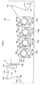
Fig. 1 is a cross-sectional view of an image forming device according to a first exemplary embodiment of the present invention; -
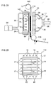
Fig. 2A is a cross sectional view of a fixing device according to the first exemplary embodiment of the invention, andFig. 2B is a front view of a fixing unit according to the first exemplary embodiment of the invention; -
Figs. 3A and 3B are schematic diagrams showing a recording paper jam detection method according to the first exemplary embodiment of the invention; -
Fig. 4 is a cross-sectional view showing a state during recording paper jam in the fixing device according to the first exemplary embodiment of the invention; -
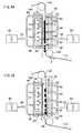
Figs. 5A and 5B are cross-sectional views of the fixing device according to a second exemplary embodiment of the invention; -
Figs. 6A to 6C are cross-sectional views of the fixing device according to a third exemplary embodiment of the invention; and -
Figs. 7A and 7B are perspective views of the fixing device according to a fourth exemplary embodiment of the invention. - A first exemplary embodiment of an image forming device of the invention will be described with reference to the drawings.
- As shown in
Fig. 1 , animage forming device 100 for performing flash fixing for fixing by an irradiation heat of a xenon lump or the like after forming an image is provided. - The
image forming device 100 forms the image onrecording paper 112, formed of continuous form paper capable of being cut, as one example of the paper. - The
recording paper 112 inserted into theimage forming device 100 from an arrow IN direction is wrapped aroundwrapping rollers image forming device 100 at a constant speed. - On a lower side of the feeding path of the
recording paper 112,image forming units - Each of the
image forming units 118A to 118D is provided with aphotosensitive drum 120, which has the same configuration except the color of the toner image to be formed, and is arranged such that an axis line thereof is orthogonal to a feeding direction of therecording paper 112. - A
charger 122 for charging thephotosensitive drum 120 is provided around thephotosensitive drum 120. Anexposure device 124 for irradiating a chargedphotosensitive drum 120 with an LED light to form an electrostatic latent image is provided on a downstream side of thecharger 122 in a rotation direction of thephotosensitive drum 120. - A developing
device 126 for forming the toner image by supplying a toner of a predetermined color to the electrostatic latent image on thephotosensitive drum 120 is provided on a downstream side of theexposure device 124. - A transferring
device 128 arranged so as to be opposed to thephotosensitive drum 120 with the feeding path of therecording paper 112 interposed therebetween for transferring the toner image on therecording paper 112 is provided on a downstream side of the developingdevice 126. - A
discharger 130 for discharging a surface of thephotosensitive drum 120, acleaner blade 132 for removing residual toner on the surface of thephotosensitive drum 120, and acleaner brush 134 are arranged on a downstream side of thetransferring device 128. - Herein, when printing in color, the
image forming units 118A to 118D form the toner images of which colors are different to one another on the peripheral surfaces of thephotosensitive drums 120 by thechargers 122, theexposure devices 124, and the developingdevices 126, and thereafter, transfer the toner images on therecording paper 112 by the transferringdevices 128. - In a series of process of charge, exposure (electrostatic latent image forming), develop (toner image forming) and transfer in the
image forming units 118A to 118D, an execution timing thereof is controlled such that the toner images formed at theimage forming units 118A to 118D are overlapped to one another on therecording paper 112. Thereby, a full-color toner image is formed on therecording paper 112. - Also, when printing monochrome image, the
image forming unit 118D for black is driven to form a black toner image on the peripheral surface of thephotosensitive drum 120 by thecharger 122, theexposure device 124 and the developingdevice 126, and thereafter, by transferring the toner image on therecording paper 112 by the transferringunit 128, the black toner image is formed on therecording paper 112. - In the feeding path of the
recording paper 112, the feeding direction is changed to a substantially vertical direction by a wrappingroller 138 on a downstream side of positions of theimage forming units 118A to 118D. - In a section between the wrapping
roller 138 and awrapping roller 142 at a downstream side of the wrappingroller 138, therecording paper 112 is fed upward in the substantially vertical direction. A fixingdevice 10 is arranged on the feeding path between the wrappingrollers - The fixing
device 10 is provided with aflash fixing unit 140 as one example of a fixing unit and anair intake unit 11 as one example of an air intake part. - A
tension roller 144 is provided at a downstream side of the wrappingroller 142. - Detection part such as a pressure sensor or an optical position sensor not shown is provided on the
tension roller 144. Also, a portion of an outer peripheral side surface of thetension roller 144 abuts therecording paper 112, and thetension roller 144 is energized in a direction to press therecording paper 112 to a lower side by using a spring or the like. - Herein, as shown in
Fig. 3A , at the time of ordinary use of theimage forming device 100, therecording paper 112 is tightened with a predetermined tension, and thetension roller 144 is at a position at which the above-described energizing force and the tension of therecording paper 112 are balanced. - On the other hand, as shown in
Fig. 3B , when a jam occurs and therecording paper 112 is cut, the tension of therecording paper 112 is weakened, so that the position of thetension roller 144 lowers from a general position (two-dot chain line) to a lower position (solid line) by the energizing force. - By detecting this change in position of the
tension roller 144 by the above-described pressure sensor or optical position sensor, the jam of therecording paper 112 is detected. - Also, as shown in
Fig. 1 , the wrappingrollers tension roller 144, and it is configured that therecording paper 112 on which the toner image is fixed is guided to the wrappingrollers image forming device 100. - Next, the fixing
device 10 will be described. - The fixing
device 10 is provided with theflash fixing unit 140 and theair intake unit 11 as described above. - As shown in
Fig. 2 , theflash fixing unit 140 has ahousing 12 in a box-shape one planar surface of which is opened, and is provided withflash lumps 14 in thehousing 12, as one example of six heat sources emitting the flash light. - The
flash lamps 14 emits the flash light by a voltage supplied from a power supply not shown to fuse a toner T on therecording paper 112 by energy of the flash light, thereby fixing the toner image transferred on therecording paper 112. - A
cover glass 16 is arranged on a front surface side of theflash lamps 14 and the feeding path side of therecording paper 112. - The
cover glass 16 as one example of a protective glass is fixed to thehousing 12 by adhesion to prevent intrusion of dust or the like into theflash fixing unit 140, and prevents therecording paper 112 and theflash lamps 14 from contacting each other. - Also, plural penetrating air-through
holes housing 12 so as to enclose theflash lamps 14. One end of each ofstainless pipes holes fan 26. - The
fan 26 as one example of an air sending part is driven by power supplied by power supply means not shown to supply air to thepipes - Thereby, when the power is supplied to the
fan 26 by the power supply means, air is supplied to thepipes holes 18 to 21 toward therecording paper 112. - The air sending part is formed from the
fan 26, thepipes holes 18 to 21. - The
air intake unit 11 is arranged on a position opposed to the front surface of theflash fixing unit 140 with the feeding path of therecording paper 112 interposed therebetween. - The
air intake unit 11 as one example of a contact prevention unit has aside plate 28, aduct 32, anair intake device 34 and apipe 38. - The
side plate 28 is fixed so as to be apart from therecording paper 112 by a predetermined distance, and plural air intake holes 30 penetrating toward therecording paper 112, are formed therein. Also, theduct 32 is provided on a surface opposite to therecording paper 112 of theside plate 28 so as to cover the air intake holes 30. - An opening is formed on one end portion of the
duct 32, and theair intake device 34 is fixed to the opening by a screw, an adhesive or the like. Also, an inclined surface to make an air flow be stable during air intake is formed in theduct 32. - The
air intake device 34 is provided with afan 36 rotating by driving means such as a motor or the like not shown inside thereof. In addition, apipe 38 for discharging intaken air outside of theimage forming device 100 is connected to theair intake device 34. - Thereby, when the
air intake device 34 is driven, thefan 36 rotates and intakes air through the air intake holes 30, and the intaken air is discharged from theduct 32 through thefan 36 to thepipe 38. - Note that, the contact prevention unit of this exemplary embodiment is formed of the air sending part from the
fan 26 to the air throughholes 18 to 21, and theair intake unit 11. - Also, it is configured that when the jam is detected, a jam detection signal is sent to a driving unit not shown and the driving unit drives the
fan 26 and theair intake device 34. - Next, function of the first exemplary embodiment of the invention will be described.
- As shown in
Figs. 3 and4 , when the jam of therecording paper 112 occurs during operation of the image forming device 100 (refer toFig. 1 ) and therecording paper 112 is cut, the position of thetension roller 144 lowers and the jam is detected by the above-described sensor. - The fan 26 (refer to
Fig. 2 ) and theair intake device 34 are driven by the jam detection signal. - Air sent from an arrow A direction is blown on a recording surface side of the
recording paper 112, and a rear surface side of therecording paper 112 is sucked to aside plate 28 side by the air intaken in an arrow B direction. - Thereby, the
recording paper 112 is kept away from thecover glass 16 of theflash fixing unit 140. - Next, a second exemplary embodiment of the fixing device and the image forming device of the invention will be described with reference to the drawings.
- The same reference numeral as that in the above-described first exemplary embodiment is given to the basically same component as that in the above-described first exemplary embodiment, and the description thereof is omitted.
- As shown in
Figs. 5A and 5B , one end of each ofstainless pipes holes flash fixing unit 140, respectively, and thepipes pipe 44 by a three-way joint not shown and inner sides thereof are communicated to one another. The other end of thepipe 44 is connected to afirst fan 42. - It is configured that the
first fan 42 is driven by the power supplied from power supplying unit not shown, and supplies air to thepipe 44. - Thereby, it is configured that when the
first fan 42 is driven by the power supplied from the power supplying unit, air is supplied through thepipe 44 to thepipes holes 18 to 21 toward therecording paper 112 in an arrow D direction. - On the other hand, an
air sending unit 40 is arranged on a position opposed to the front surface of theflash fixing unit 140 with the feeding path of therecording paper 112 interposed therebetween. - The
air sending unit 40 as one example of a reverse air sending part has aside plate 50 seperated from therecording paper 112 with a predetermined distance therebetween, apipe 54, and asecond fan 58. - A plurality of air-through
holes 52 penetrating toward therecording paper 112 are formed in theside plate 50. A plurality ofpipes 54 are arranged on a surface opposite to therecording paper 112 on theside plate 50, and the air-throughholes 52 and thepipes 54 are connected and fixed. - The other end of the
pipe 54 is connected to onepipe 56 by a joint not shown, and the other end of thepipe 56 is connected to asecond fan 58. - It is configured that the
second fan 58 is driven by the power supplied from power supplying unit not shown to supply air to thepipe 56. - Thereby, when the
second fan 58 is driven, air is supplied through thepipe 56 to a plurality ofpipes 54, and air is sent from a plurality of air-throughholes 52 toward the rear surface of therecording paper 112 in an arrow C direction. - Next, function of the second exemplary embodiment of the invention will be described.
- In the image forming device 100 (refer to
Fig. 1 ), thesecond fan 58 is driven during fixation on therecording paper 112. Air supplied from thesecond fan 58 is sent through thepipes - Thereby, the
recording paper 112 gets close to aflash fixing unit 140 side by air sent from the arrow C direction, and heat by light emission of the flash lumps 14 is transmitted to the toner T on therecording paper 112. - On the other hand, when the
recording paper 112 is cut during the jam of therecording paper 112, the jam detection device in the above-described tension roller 144 (refer toFig. 3 ) activates to drive thefirst fan 42. Air sent from thefirst fan 42 is sent from thepipe 44 through thepipe - Thereby, the
recording paper 112 is kept apart from thecover glass 16. - Next, a third exemplary embodiment of the fixing device and the image forming device of the invention will be described with reference to the drawings.
- The same reference numeral as that in the above-described first exemplary embodiment is given to the basically same component as that in the above-described first exemplary embodiment, and the description thereof is omitted.
- As shown in
Figs. 6A to 6C , aflash fixing unit 70 is provided in theimage forming device 100. - In the
flash fixing unit 70 as one example of the fixing unit, flash lumps 74 as one example of six heat sources are arranged in ahousing 72 in a box-shape having an opening on one side, and the opening is covered with thecover glass 76. - An
electrostatic absorption device 60 is arranged at a position opposed to thecover glass 76 with a predetermined distance therebetween. - The
electrostatic absorption device 60 as one example of electrostatic force generation part is configured such that a plasticcomposite plate 62 in which an electrode not shown is included is arranged on abase 64 for fixed positioning. - One end of a
cable 66 for supplying direct current voltage is connected to the electrode in the plasticcomposite plate 62. The other end of thecable 66 is connected to apower supply 68 for outputting the direct current voltage. - A charged polar character of the toner T in this exemplary embodiment is set to positive.
- Next, function of the third exemplary embodiment of the invention will be described.
- As shown in
Fig. 6A , during fixation on therecording paper 112, the direct current voltage is not output from thepower supply 68 to the electrode inside the plasticcomposite plate 62, and therecording paper 112 passes between theflash fixing unit 70 and theelectrostatic absorption device 60 without being absorbed. - Next, as shown in
Fig. 6B , when therecording paper 112 is cut during the jam of therecording paper 112, the jam detection device in the above-described tension roller 144 (refer toFig. 3 ) activates to drive thepower supply 68. - By the drive of the
power supply 68, the direct current voltage is supplied to the electrode in the plasticcomposite plate 62, and a surface of the plasticcomposite plate 62 charges negatively. - Herein, as shown in
Fig. 6C , the polar character of the toner T after transferring is positive, and the polar character on a surface side of therecording paper 112, which contacts the toner T, is negative. - In addition, the polar character of the rear surface side of the
recording paper 112, which does not contact the toner T, is positive. - Therefore, the
recording paper 112 is drawn in an arrow E direction by a Coulomb attraction between a negative charge on the surface of the plasticcomposite plate 62 and a positive charge on the rear surface side of therecording paper 112. - Thereby, the
recording paper 112 is kept apart from thecover glass 76. - Next, a fourth exemplary embodiment of the fixing device and the image forming device of the invention will be described with reference to the drawings.
- The same reference numeral as that of the above-described first exemplary embodiment is given to the basically same component as that of the above-described first exemplary embodiment, and the description thereof is omitted.
- As shown in
Fig. 7A , aflash fixing unit 90 is provided inside the image forming device 100 (refer toFig. 1 ). - In the
flash fixing unit 90 as one example of the fixing unit, flash lumps 92 as one example of six heat sources are arranged in ahousing 91 in a box-shape having an opening on one side, and the opening is covered with acover glass 94. - Moving
units 80 are provided at positions next to right and left side surfaces of theflash fixing unit 90. - The moving
unit 80 is composed ofguide rails 82, a movingplate 84, ashaft 88, and asolenoid 86. - A pair of the guide rails 82 set at an upper and lower positions are provided adjacent to the right and left side surfaces of the
flash fixing unit 90 respectively, and the movingplate 84 is inserted between the upper and lower pair of guide rails 82. - The moving
plate 84 has anabutment surface 85 abutting therecording paper 112 when detecting the jam of therecording paper 112, and one end of theshaft 88 is fixed to a side surface opposite to theabutment surface 85 of the movingplate 84 by fitting or adhesion. Also, the other end of theshaft 88 is fixed to an axis core not shown of thesolenoid 86. - In the
solenoid 86, a magnetic field generates by electric current supplied from a power supply not shown and the axis core moves in a linear line. Thereby, when the electric current is supplied to thesolenoid 86, theshaft 88 moves in a linear line, thereby thetransfer plate 84 is movable along the guide rails 82. - Next, function of the fourth exemplary embodiment of the invention will be described.
- During the jam of the
recording paper 112, the jam detection device in the above-described tension roller 144 (refer toFig. 3 ) activates, and the electric current is supplied from the power supply not shown to thesolenoid 86. - When the electric current is supplied to the
solenoid 86, theshaft 88 moves in an arrow F direction, and the movingplate 84 moves along the guide rails 82 in the arrow F direction. - The
abutment surface 85 of thetransfer plate 84 presses both end portions of therecording paper 112 in an arrow G direction, and therecording paper 112 is moved from thecover glass 76. - In this manner, the
recording paper 112 is kept apart from thecover glass 76. - The invention is not limited to the above-described exemplary embodiments.
- The fixing
device 10 may be provided in a horizontal direction and an oblique direction, other than the vertical direction. - The number of the
flash lamps - The number of
pipes - The
recording paper 112 may be kept apart from thecover glass 16 by using a cam mechanism instead of thesolenoid 86. - The foregoing description of the exemplary embodiments of the present invention has been provided for the purposes of illustration and description. It is not intended to be exhaustive or to limit the invention to the precise forms disclosed. Obviously, many modifications and variations will be apparent to practitioners skilled in the art. The exemplary embodiments were chosen and described in order to best explain the principles of the invention and its practical applications, thereby enabling others skilled in the art to understand the invention for various embodiments and with the various modifications as are suited to the particular use contemplated. It is intended that the scope of the invention be defined by the following claims and their equivalent.
Claims (15)
- A fixing device comprising:a fixing unit comprising a heat source for fixing a toner image on a sheet in a state of being out of contact with the sheet; anda contact prevention unit preventing contact of the fixing unit and the sheet.
- The fixing device of Claim 1, wherein the contact prevention unit comprises an air sending part sending air in a direction from the fixing unit toward the sheet to keep the sheet away from the fixing unit.
- The fixing device of Claim 1 or 2, wherein the contact prevention unit comprises an air intake part arranged at a position opposed to the fixing unit and intaking air to keep the sheet away from the fixing unit.
- The fixing device of Claim 1, wherein the contact prevention unit comprises an air sending part sending air in a direction from the fixing unit toward the sheet and an air intake part arranged at a position opposed to the fixing unit and intaking air; and the contact prevention unit keeps the sheet away from the fixing unit with the air sending part and the air intake part.
- The fixing device of Claim 1 or 2, wherein the contact prevention unit comprises an electrostatic force generation part provided at a position opposed to the fixing unit and keeps the sheet away from the fixing unit by electrostatic attracting force.
- The fixing device of Claim 2, further comprising a reverse air sending part arranged at a position opposed to the fixing unit and sending air in a direction from the sheet toward the fixing unit to put the sheet close to the fixing unit, wherein during fixing, the reverse air sending part sends air to the sheet, and during non-fixing, the operation of the reverse air sending part is stopped and the air sending part sends air to the sheet.
- The fixing device of any one of Claims 1 through 6, wherein the fixing unit comprises the heat source and a protective glass for shielding the heat source, and the contact prevention unit prevents contact of the sheet and the protective glass.
- The fixing device of Claim 1, wherein the contact prevention unit comprises a moving part abutting the sheet to keep the sheet away from the fixing unit.
- A fixing method comprising keeping sheet away from a fixing unit with a contact prevention unit when a sheet jam has occured.
- The fixing method according to Claim 9, wherein the contact prevention unit comprises an air sending part, and the air sending part sends air toward the sheet to keep the sheet away from the fixing unit.
- The fixing method according to Claim 9 or 10, wherein the contact prevention unit comprises an air intake part, and the air intake part intakes air to attract the sheet and keep the sheet away from the fixing unit.
- The fixing method according to Claim 9, wherein the contact prevention unit comprises an air sending part and an air intake part, and the sheet is kept away from the fixing unit by sending air to one surface of the sheet with the air sending part and intaking air to attract the other surface of the sheet with the air intake part.
- The fixing method according to Claim 9 or 10, wherein the sheet is moved close to the fixing unit with a reverse air sending part when a sheet jam does not occur, and operation of the reverse air sending part is stopped when a sheet jam occurs.
- The fixing method according to Claim 9 or 10, wherein the contact prevention unit comprises an electrostatic force generation part, and the electrostatic force generation part attracts the sheet to keep the sheet away from the fixing unit by electrostatic attracting force.
- The fixing method according to Claim 9, wherein the contact prevention unit comprises a moving part, and the moving part abuts the sheet to keep the sheet away from the fixing unit.
Applications Claiming Priority (1)
| Application Number | Priority Date | Filing Date | Title |
|---|---|---|---|
| JP2007021251A JP4858196B2 (en) | 2007-01-31 | 2007-01-31 | Fixing device |
Publications (1)
| Publication Number | Publication Date |
|---|---|
| EP1953598A1 true EP1953598A1 (en) | 2008-08-06 |
Family
ID=39263123
Family Applications (1)
| Application Number | Title | Priority Date | Filing Date |
|---|---|---|---|
| EP08001261A Withdrawn EP1953598A1 (en) | 2007-01-31 | 2008-01-24 | Fixing device and fixing method |
Country Status (3)
| Country | Link |
|---|---|
| US (1) | US20080181685A1 (en) |
| EP (1) | EP1953598A1 (en) |
| JP (1) | JP4858196B2 (en) |
Cited By (1)
| Publication number | Priority date | Publication date | Assignee | Title |
|---|---|---|---|---|
| EP3940457A4 (en) * | 2019-03-12 | 2022-12-21 | Fujifilm Business Innovation Corp. | FIXATION DEVICE AND IMAGE FORMING APPARATUS |
Families Citing this family (4)
| Publication number | Priority date | Publication date | Assignee | Title |
|---|---|---|---|---|
| JP6907889B2 (en) * | 2017-10-31 | 2021-07-21 | コニカミノルタ株式会社 | Image forming device and program |
| JP7139979B2 (en) * | 2019-01-31 | 2022-09-21 | 富士フイルムビジネスイノベーション株式会社 | Fixing device, image forming device |
| WO2020170471A1 (en) * | 2019-02-20 | 2020-08-27 | 富士ゼロックス株式会社 | Image forming device |
| JP2024074707A (en) * | 2022-11-21 | 2024-05-31 | 富士フイルムビジネスイノベーション株式会社 | Fixing device and image forming apparatus |
Citations (6)
| Publication number | Priority date | Publication date | Assignee | Title |
|---|---|---|---|---|
| JPS61138275A (en) * | 1984-12-10 | 1986-06-25 | Nippon Denki Kanji Syst Kk | Flash fixing device |
| US4668073A (en) * | 1984-05-04 | 1987-05-26 | Dainippon Screen Mfg. Co., Ltd. | Fixing apparatus |
| JPH0830138A (en) * | 1994-07-21 | 1996-02-02 | Fujitsu Ltd | Image forming device |
| JPH0980960A (en) * | 1995-09-19 | 1997-03-28 | Fujitsu Ltd | Image forming apparatus and fixing unit |
| JP2002229418A (en) | 2001-01-31 | 2002-08-14 | Toray Eng Co Ltd | Image forming device and image forming method |
| US20020191993A1 (en) * | 2000-12-22 | 2002-12-19 | Gerhard Bartscher | Digital printing or copying machine |
Family Cites Families (4)
| Publication number | Priority date | Publication date | Assignee | Title |
|---|---|---|---|---|
| JPS61254972A (en) * | 1985-05-07 | 1986-11-12 | Hitachi Ltd | Paper dry fixing method |
| JP3770012B2 (en) * | 1999-11-16 | 2006-04-26 | コニカミノルタビジネステクノロジーズ株式会社 | Flash fixing device |
| DE10143988A1 (en) * | 2000-12-22 | 2002-08-14 | Nexpress Solutions Llc | Digital printing or copying machine |
| JP2006324225A (en) * | 2004-06-30 | 2006-11-30 | Ricoh Co Ltd | Heating device, sheet member heating device, rotating body heating device, fixing device, and image forming apparatus using them |
-
2007
- 2007-01-31 JP JP2007021251A patent/JP4858196B2/en not_active Expired - Fee Related
-
2008
- 2008-01-23 US US12/018,465 patent/US20080181685A1/en not_active Abandoned
- 2008-01-24 EP EP08001261A patent/EP1953598A1/en not_active Withdrawn
Patent Citations (6)
| Publication number | Priority date | Publication date | Assignee | Title |
|---|---|---|---|---|
| US4668073A (en) * | 1984-05-04 | 1987-05-26 | Dainippon Screen Mfg. Co., Ltd. | Fixing apparatus |
| JPS61138275A (en) * | 1984-12-10 | 1986-06-25 | Nippon Denki Kanji Syst Kk | Flash fixing device |
| JPH0830138A (en) * | 1994-07-21 | 1996-02-02 | Fujitsu Ltd | Image forming device |
| JPH0980960A (en) * | 1995-09-19 | 1997-03-28 | Fujitsu Ltd | Image forming apparatus and fixing unit |
| US20020191993A1 (en) * | 2000-12-22 | 2002-12-19 | Gerhard Bartscher | Digital printing or copying machine |
| JP2002229418A (en) | 2001-01-31 | 2002-08-14 | Toray Eng Co Ltd | Image forming device and image forming method |
Cited By (4)
| Publication number | Priority date | Publication date | Assignee | Title |
|---|---|---|---|---|
| EP3940457A4 (en) * | 2019-03-12 | 2022-12-21 | Fujifilm Business Innovation Corp. | FIXATION DEVICE AND IMAGE FORMING APPARATUS |
| US11940745B2 (en) | 2019-03-12 | 2024-03-26 | Fujifilm Business Innovation Corp. | Fixing device and image forming apparatus |
| AU2023202384B2 (en) * | 2019-03-12 | 2024-09-19 | Fujifilm Business Innovation Corp. | Fixing device and image forming apparatus |
| US12313989B2 (en) | 2019-03-12 | 2025-05-27 | Fujifilm Business Innovation Corp. | Fixing device and image forming apparatus |
Also Published As
| Publication number | Publication date |
|---|---|
| US20080181685A1 (en) | 2008-07-31 |
| JP2008185925A (en) | 2008-08-14 |
| JP4858196B2 (en) | 2012-01-18 |
Similar Documents
| Publication | Publication Date | Title |
|---|---|---|
| US12072646B2 (en) | Image forming apparatus | |
| CN100594444C (en) | Image forming apparatus capable of reducing toner scattering on recording medium and its guide | |
| US20080181685A1 (en) | Fixing device and fixing method | |
| CN108459479B (en) | Fixing device and image forming device | |
| US12353155B2 (en) | Static elimination apparatus and image forming system | |
| KR101214406B1 (en) | Image forming apparatus | |
| JP2012032487A (en) | Image forming apparatus | |
| CN102654747B (en) | Image processing system | |
| JP5644391B2 (en) | Electrical connection structure, image forming apparatus | |
| US20130251418A1 (en) | Fixing device and image forming apparatus | |
| US7983607B2 (en) | Image forming apparatus having an endless conveying belt with a 720 degree twist | |
| JP6288463B2 (en) | Image forming apparatus | |
| JP2004126529A (en) | Image forming device | |
| JP2010256562A (en) | Image forming apparatus | |
| JP2013077005A (en) | Image forming apparatus | |
| CN103105759B (en) | image forming device | |
| JP6380758B2 (en) | Image forming apparatus | |
| KR100580220B1 (en) | Rotational force control device of the image forming apparatus | |
| JP6872109B2 (en) | Image forming device | |
| JP2013167671A (en) | Image forming apparatus | |
| JP2010032693A (en) | Image forming apparatus | |
| JPH09218590A (en) | Image forming device | |
| JPH1111728A (en) | Image forming device | |
| JP2012003010A (en) | Cleaning structure and image forming apparatus | |
| JP2008185881A (en) | Charging device and image forming apparatus |
Legal Events
| Date | Code | Title | Description |
|---|---|---|---|
| PUAI | Public reference made under article 153(3) epc to a published international application that has entered the european phase |
Free format text: ORIGINAL CODE: 0009012 |
|
| AK | Designated contracting states |
Kind code of ref document: A1 Designated state(s): AT BE BG CH CY CZ DE DK EE ES FI FR GB GR HR HU IE IS IT LI LT LU LV MC MT NL NO PL PT RO SE SI SK TR |
|
| AX | Request for extension of the european patent |
Extension state: AL BA MK RS |
|
| 17P | Request for examination filed |
Effective date: 20081007 |
|
| AKX | Designation fees paid |
Designated state(s): AT BE BG CH CY CZ DE DK EE ES FI FR GB GR HR HU IE IS IT LI LT LU LV MC MT NL NO PL PT RO SE SI SK TR |
|
| 17Q | First examination report despatched |
Effective date: 20100127 |
|
| STAA | Information on the status of an ep patent application or granted ep patent |
Free format text: STATUS: THE APPLICATION IS DEEMED TO BE WITHDRAWN |
|
| 18D | Application deemed to be withdrawn |
Effective date: 20140801 |