EP1953367A2 - Vehicle engine idle speed control - Google Patents
Vehicle engine idle speed control Download PDFInfo
- Publication number
- EP1953367A2 EP1953367A2 EP08250333A EP08250333A EP1953367A2 EP 1953367 A2 EP1953367 A2 EP 1953367A2 EP 08250333 A EP08250333 A EP 08250333A EP 08250333 A EP08250333 A EP 08250333A EP 1953367 A2 EP1953367 A2 EP 1953367A2
- Authority
- EP
- European Patent Office
- Prior art keywords
- engine
- clutch
- rotational speed
- vehicle
- output shaft
- Prior art date
- Legal status (The legal status is an assumption and is not a legal conclusion. Google has not performed a legal analysis and makes no representation as to the accuracy of the status listed.)
- Granted
Links
Images


Classifications
-
- F—MECHANICAL ENGINEERING; LIGHTING; HEATING; WEAPONS; BLASTING
- F02—COMBUSTION ENGINES; HOT-GAS OR COMBUSTION-PRODUCT ENGINE PLANTS
- F02D—CONTROLLING COMBUSTION ENGINES
- F02D31/00—Use of speed-sensing governors to control combustion engines, not otherwise provided for
- F02D31/001—Electric control of rotation speed
- F02D31/002—Electric control of rotation speed controlling air supply
- F02D31/003—Electric control of rotation speed controlling air supply for idle speed control
-
- F—MECHANICAL ENGINEERING; LIGHTING; HEATING; WEAPONS; BLASTING
- F02—COMBUSTION ENGINES; HOT-GAS OR COMBUSTION-PRODUCT ENGINE PLANTS
- F02D—CONTROLLING COMBUSTION ENGINES
- F02D41/00—Electrical control of supply of combustible mixture or its constituents
- F02D41/02—Circuit arrangements for generating control signals
- F02D41/021—Introducing corrections for particular conditions exterior to the engine
- F02D41/0215—Introducing corrections for particular conditions exterior to the engine in relation with elements of the transmission
- F02D41/022—Introducing corrections for particular conditions exterior to the engine in relation with elements of the transmission in relation with the clutch status
-
- F—MECHANICAL ENGINEERING; LIGHTING; HEATING; WEAPONS; BLASTING
- F02—COMBUSTION ENGINES; HOT-GAS OR COMBUSTION-PRODUCT ENGINE PLANTS
- F02D—CONTROLLING COMBUSTION ENGINES
- F02D41/00—Electrical control of supply of combustible mixture or its constituents
- F02D41/02—Circuit arrangements for generating control signals
- F02D41/14—Introducing closed-loop corrections
- F02D41/1401—Introducing closed-loop corrections characterised by the control or regulation method
- F02D2041/1413—Controller structures or design
- F02D2041/1422—Variable gain or coefficients
-
- F—MECHANICAL ENGINEERING; LIGHTING; HEATING; WEAPONS; BLASTING
- F02—COMBUSTION ENGINES; HOT-GAS OR COMBUSTION-PRODUCT ENGINE PLANTS
- F02D—CONTROLLING COMBUSTION ENGINES
- F02D41/00—Electrical control of supply of combustible mixture or its constituents
- F02D41/22—Safety or indicating devices for abnormal conditions
- F02D2041/227—Limping Home, i.e. taking specific engine control measures at abnormal conditions
-
- F—MECHANICAL ENGINEERING; LIGHTING; HEATING; WEAPONS; BLASTING
- F02—COMBUSTION ENGINES; HOT-GAS OR COMBUSTION-PRODUCT ENGINE PLANTS
- F02D—CONTROLLING COMBUSTION ENGINES
- F02D2200/00—Input parameters for engine control
- F02D2200/02—Input parameters for engine control the parameters being related to the engine
- F02D2200/04—Engine intake system parameters
- F02D2200/0404—Throttle position
-
- F—MECHANICAL ENGINEERING; LIGHTING; HEATING; WEAPONS; BLASTING
- F02—COMBUSTION ENGINES; HOT-GAS OR COMBUSTION-PRODUCT ENGINE PLANTS
- F02D—CONTROLLING COMBUSTION ENGINES
- F02D2200/00—Input parameters for engine control
- F02D2200/50—Input parameters for engine control said parameters being related to the vehicle or its components
- F02D2200/501—Vehicle speed
-
- F—MECHANICAL ENGINEERING; LIGHTING; HEATING; WEAPONS; BLASTING
- F02—COMBUSTION ENGINES; HOT-GAS OR COMBUSTION-PRODUCT ENGINE PLANTS
- F02D—CONTROLLING COMBUSTION ENGINES
- F02D2400/00—Control systems adapted for specific engine types; Special features of engine control systems not otherwise provided for; Power supply, connectors or cabling for engine control systems
- F02D2400/12—Engine control specially adapted for a transmission comprising a torque converter or for continuously variable transmissions
-
- F—MECHANICAL ENGINEERING; LIGHTING; HEATING; WEAPONS; BLASTING
- F02—COMBUSTION ENGINES; HOT-GAS OR COMBUSTION-PRODUCT ENGINE PLANTS
- F02D—CONTROLLING COMBUSTION ENGINES
- F02D31/00—Use of speed-sensing governors to control combustion engines, not otherwise provided for
- F02D31/001—Electric control of rotation speed
- F02D31/002—Electric control of rotation speed controlling air supply
- F02D31/003—Electric control of rotation speed controlling air supply for idle speed control
- F02D31/004—Electric control of rotation speed controlling air supply for idle speed control by controlling a throttle stop
-
- F—MECHANICAL ENGINEERING; LIGHTING; HEATING; WEAPONS; BLASTING
- F02—COMBUSTION ENGINES; HOT-GAS OR COMBUSTION-PRODUCT ENGINE PLANTS
- F02D—CONTROLLING COMBUSTION ENGINES
- F02D31/00—Use of speed-sensing governors to control combustion engines, not otherwise provided for
- F02D31/001—Electric control of rotation speed
- F02D31/002—Electric control of rotation speed controlling air supply
- F02D31/003—Electric control of rotation speed controlling air supply for idle speed control
- F02D31/005—Electric control of rotation speed controlling air supply for idle speed control by controlling a throttle by-pass
-
- F—MECHANICAL ENGINEERING; LIGHTING; HEATING; WEAPONS; BLASTING
- F02—COMBUSTION ENGINES; HOT-GAS OR COMBUSTION-PRODUCT ENGINE PLANTS
- F02D—CONTROLLING COMBUSTION ENGINES
- F02D41/00—Electrical control of supply of combustible mixture or its constituents
- F02D41/02—Circuit arrangements for generating control signals
- F02D41/14—Introducing closed-loop corrections
- F02D41/1401—Introducing closed-loop corrections characterised by the control or regulation method
-
- F—MECHANICAL ENGINEERING; LIGHTING; HEATING; WEAPONS; BLASTING
- F02—COMBUSTION ENGINES; HOT-GAS OR COMBUSTION-PRODUCT ENGINE PLANTS
- F02D—CONTROLLING COMBUSTION ENGINES
- F02D41/00—Electrical control of supply of combustible mixture or its constituents
- F02D41/22—Safety or indicating devices for abnormal conditions
-
- F—MECHANICAL ENGINEERING; LIGHTING; HEATING; WEAPONS; BLASTING
- F16—ENGINEERING ELEMENTS AND UNITS; GENERAL MEASURES FOR PRODUCING AND MAINTAINING EFFECTIVE FUNCTIONING OF MACHINES OR INSTALLATIONS; THERMAL INSULATION IN GENERAL
- F16H—GEARING
- F16H61/00—Control functions within control units of change-speed- or reversing-gearings for conveying rotary motion ; Control of exclusively fluid gearing, friction gearing, gearings with endless flexible members or other particular types of gearing
- F16H61/12—Detecting malfunction or potential malfunction, e.g. fail safe; Circumventing or fixing failures
- F16H2061/1208—Detecting malfunction or potential malfunction, e.g. fail safe; Circumventing or fixing failures with diagnostic check cycles; Monitoring of failures
-
- F—MECHANICAL ENGINEERING; LIGHTING; HEATING; WEAPONS; BLASTING
- F16—ENGINEERING ELEMENTS AND UNITS; GENERAL MEASURES FOR PRODUCING AND MAINTAINING EFFECTIVE FUNCTIONING OF MACHINES OR INSTALLATIONS; THERMAL INSULATION IN GENERAL
- F16H—GEARING
- F16H61/00—Control functions within control units of change-speed- or reversing-gearings for conveying rotary motion ; Control of exclusively fluid gearing, friction gearing, gearings with endless flexible members or other particular types of gearing
- F16H61/12—Detecting malfunction or potential malfunction, e.g. fail safe; Circumventing or fixing failures
- F16H2061/1256—Detecting malfunction or potential malfunction, e.g. fail safe; Circumventing or fixing failures characterised by the parts or units where malfunctioning was assumed or detected
- F16H2061/1284—Detecting malfunction or potential malfunction, e.g. fail safe; Circumventing or fixing failures characterised by the parts or units where malfunctioning was assumed or detected the failing part is a sensor
-
- F—MECHANICAL ENGINEERING; LIGHTING; HEATING; WEAPONS; BLASTING
- F16—ENGINEERING ELEMENTS AND UNITS; GENERAL MEASURES FOR PRODUCING AND MAINTAINING EFFECTIVE FUNCTIONING OF MACHINES OR INSTALLATIONS; THERMAL INSULATION IN GENERAL
- F16H—GEARING
- F16H61/00—Control functions within control units of change-speed- or reversing-gearings for conveying rotary motion ; Control of exclusively fluid gearing, friction gearing, gearings with endless flexible members or other particular types of gearing
- F16H61/12—Detecting malfunction or potential malfunction, e.g. fail safe; Circumventing or fixing failures
-
- F—MECHANICAL ENGINEERING; LIGHTING; HEATING; WEAPONS; BLASTING
- F16—ENGINEERING ELEMENTS AND UNITS; GENERAL MEASURES FOR PRODUCING AND MAINTAINING EFFECTIVE FUNCTIONING OF MACHINES OR INSTALLATIONS; THERMAL INSULATION IN GENERAL
- F16H—GEARING
- F16H61/00—Control functions within control units of change-speed- or reversing-gearings for conveying rotary motion ; Control of exclusively fluid gearing, friction gearing, gearings with endless flexible members or other particular types of gearing
- F16H61/66—Control functions within control units of change-speed- or reversing-gearings for conveying rotary motion ; Control of exclusively fluid gearing, friction gearing, gearings with endless flexible members or other particular types of gearing specially adapted for continuously variable gearings
- F16H61/662—Control functions within control units of change-speed- or reversing-gearings for conveying rotary motion ; Control of exclusively fluid gearing, friction gearing, gearings with endless flexible members or other particular types of gearing specially adapted for continuously variable gearings with endless flexible members
- F16H61/66254—Control functions within control units of change-speed- or reversing-gearings for conveying rotary motion ; Control of exclusively fluid gearing, friction gearing, gearings with endless flexible members or other particular types of gearing specially adapted for continuously variable gearings with endless flexible members controlling of shifting being influenced by a signal derived from the engine and the main coupling
- F16H61/66259—Control functions within control units of change-speed- or reversing-gearings for conveying rotary motion ; Control of exclusively fluid gearing, friction gearing, gearings with endless flexible members or other particular types of gearing specially adapted for continuously variable gearings with endless flexible members controlling of shifting being influenced by a signal derived from the engine and the main coupling using electrical or electronical sensing or control means
Definitions
- the present invention relates to a vehicle, and a control device and a control method thereof.
- the present invention relates to a vehicle having an electronic continuously variable transmission and an idle speed control device, and a control device, and a control method thereof.
- CVT Continuously variable transmissions
- ISC idle speed control
- JP-A-2004-19740 JP-A-2004-19740
- ISC is a control which uses an ISC valve and the like to change a passage area of a by-pass passage or the like in order that the amount of intake air to an engine will be increased and decreased, thus adjusting the rotational speed of the engine at a time of idling (idle rotational speed).
- ECVT Electronic continuously variable transmissions
- the transmission gear ratio can be adjusted regardless of the rotational speed of the engine. Therefore, the ECVT is widely used for vehicles such as scooters.
- the vehicle may problematically increase speed even if the rider does not open the throttle. In other words, the vehicle may increase speed regardless of the rider's intention of decreasing speed. Therefore, drivability is not desirable.
- the present invention has been made in view of the situation described above, and has an object to improve drivability of a vehicle provided with an ECVT and an idle speed control device.
- a vehicle includes: a drive wheel; an engine; an electronic continuously variable transmission having an input shaft connected to the engine and an output shaft to adjust a transmission gear ratio between the input shaft and the output shaft; a clutch located in the power transmission path between the engine and the drive wheel to be engaged and disengaged according to a rotational speed of the input shaft or output shaft; an idle speed control device for performing idle speed control to adjust an idle rotational speed of the engine; and a control unit for suppressing or stopping the idle speed control when the clutch is engaged.
- a vehicle includes: a drive wheel; an engine; an electronic continuously variable transmission having an input shaft connected to the engine and an output shaft to adjust a transmission gear ratio between the input shaft and the output shaft; a clutch located between the output shaft and the drive wheel to be engaged and disengaged according to a rotational speed of the output shaft; an idle speed control device for performing idle speed control to adjust an idle rotational speed of the engine; and a control unit for suppressing or stopping the idle speed control when the clutch is engaged.
- a vehicle includes: a drive wheel; an engine; an electronic continuously variable transmission having an input shaft connected to the engine and an output shaft to adjust a transmission gear ratio between the input shaft and the output shaft; a clutch located in the power transmission path between the engine and the drive wheel to be engaged and disengaged according to a rotational speed of the input shaft or output shaft; an idle speed control device for performing idle speed control to adjust an idle rotational speed of the engine; and a control unit for detecting the abnormality in the continuously variable transmission, and suppressing or stopping the idle speed control when the abnormality is detected in the continuously variable transmission.
- a vehicle includes: a drive wheel; an engine; an electronic continuously variable transmission having an input shaft connected to the engine and an output shaft to adjust a transmission gear ratio between the input shaft and the output shaft; a clutch located in between the engine and the drive wheel to be engaged and disengaged according to a rotational speed of the input shaft or output shaft; an idle speed control device for performing idle speed control to adjust an idle rotational speed of the engine; and a control unit for detecting the abnormality in the continuously variable transmission, and suppressing or stopping the idle speed control when the abnormality is detected in the continuously variable transmission.
- a controller for a vehicle is a controller for suppressing or stopping the idle speed control when the clutch is engaged.
- the vehicle includes: a drive wheel; an engine; an electronic continuously variable transmission having an input shaft connected to the engine and an output shaft to adjust a transmission gear ratio between the input shaft and the output shaft; a clutch located in the power transmission path between the engine and the drive wheel to be engaged and disengaged according to a rotational speed of the input shaft or output shaft; an idle speed control device for performing idle speed control to adjust an idle rotational speed of the engine.
- a controller for a vehicle is a controller that suppresses or stops the idle speed when the clutch is engaged.
- the vehicle includes: a drive wheel; an engine; an electronic continuously variable transmission having an input shaft connected to the engine and an output shaft to adjust a transmission gear ratio between the input shaft and the output shaft; a clutch located between the output shaft and the drive wheel to be engaged and disengaged according to a rotational speed of the output shaft; and an idle speed control device for performing idle speed control to adjust an idle rotational speed of the engine.
- a controller for a vehicle detects the abnormality of a continuously variable transmission.
- the controller detects the abnormality in the continuously variable transmission, the controller suppresses or stops an idle speed control.
- the vehicle includes: a drive wheel; an engine; an electronic continuously variable transmission having an input shaft connected to the engine and an output shaft to adjust a transmission gear ratio between the input shaft and the output shaft; a clutch located in the power transmission path between the engine and the drive wheel to be engaged and disengaged according to a rotational speed of the input shaft or output shaft; an idle speed control device for performing idle speed control to adjust an idle rotational speed of the engine.
- a controller for a vehicle detects the abnormality of a continuously variable transmission.
- the controller detects the abnormality in the continuously variable transmission, the controller suppresses or stops an idle speed control.
- the vehicle includes: a drive wheel; an engine; an electronic continuously variable transmission having an input shaft connected to the engine and an output shaft to adjust a transmission gear ratio between the input shaft and the output shaft; a clutch located between the output shaft and the drive wheel to be engaged and disengaged according to a rotational speed of the output shaft; and an idle speed control device for performing idle speed control to adjust an idle rotational speed of the engine.
- a control method for a vehicle is a method to suppress or stop an idle speed control when a clutch is engaged.
- the vehicle includes: a drive wheel; an engine; an electronic continuously variable transmission having an input shaft connected to the engine and an output shaft to adjust a transmission gear ratio between the input shaft and the output shaft; a clutch located in the power transmission path between the engine and the drive wheel to be engaged and disengaged according to a rotational speed of the input shaft or output shaft; an idle speed control device for performing idle speed control to adjust an idle rotational speed of the engine.
- a control method for a vehicle is a method to suppress or stop an idle speed control.
- the vehicle includes: a drive wheel; an engine; an electronic continuously variable transmission having an input shaft connected to the engine and an output shaft to adjust a transmission gear ratio between the input shaft and the output shaft; a clutch located between the output shaft and the drive wheel to be engaged and disengaged according to a rotational speed of the output shaft; and an idle speed control device for performing idle speed control to adjust an idle rotational speed of the engine.
- a control method for a vehicle is a method to detect the abnormality of a continuously variable transmission and to suppress or stop an idle speed control when the abnormality is detected.
- the vehicle includes: a drive wheel; an engine; an electronic continuously variable transmission having an input shaft connected to the engine and an output shaft to adjust a transmission gear ratio between the input shaft and the output shaft; a clutch located in the power transmission path between the engine and the drive wheel to be engaged and disengaged according to a rotational speed of the input shaft or output shaft; an idle speed control device for performing idle speed control to adjust an idle rotational speed of the engine.
- a control method for a vehicle is a method to detect the abnormality of a continuously variable transmission and to suppress or stop an idle speed control when the abnormality is detected.
- the vehicle includes: a drive wheel; an engine; an electronic continuously variable transmission having an input shaft connected to the engine and an output shaft to adjust a transmission gear ratio between the input shaft and the output shaft; a clutch located between the output shaft and the drive wheel to be engaged and disengaged according to a rotational speed of the output shaft; and an idle speed control device for performing idle speed control to adjust an idle rotational speed of the engine.
- a vehicle comprising:
- the clutch may be located in a power transmission between the engine and the drive wheel and may be adapted to be engaged or disengaged according to the rotational speed of the input shaft or the output shaft.
- the clutch may be located between the output shaft and the drive wheel and may be adapted to be engaged or disengaged according to the rotational speed of the output shaft.
- the clutch may include a first clutch member connected directly or indirectly to the output shaft, and a second clutch member connected directly or indirectly to the drive wheel.
- the second clutch member may be adapted to be engaged with or disengaged with the first clutch member according to the rotational speed of the output shaft.
- the control unit may determine an engaged or disengaged state of the clutch based on the rotational speed of the first clutch member or based on the difference of the rotational speed between the first clutch member and the second clutch member.
- the vehicle may further comprise:
- a controller for a vehicle comprising:
- the clutch may be located in a power transmission between the engine and the drive wheel and may be adapted to be engaged or disengaged according to the rotational speed of the input shaft or the output shaft.
- the clutch may be located between the output shaft and the drive wheel and may be adapted to be engaged or disengaged according to the rotational speed of the output shaft.
- a control method for a vehicle comprising:
- the clutch may be located in a power transmission between the engine and the drive wheel and may be adapted to be engaged or disengaged according to the rotational speed of the input shaft or the output shaft.
- the clutch may be located between the output shaft and the drive wheel and may be adapted to be engaged or disengaged according to the rotational speed of the output shaft.
- the input shaft of the continuously variable transmission may be connected to the engine, and the transmission is preferably adapted to adjust a gear ratio between the input shaft and the output shaft.
- the present invention will improve the drivability of a vehicle provided with an ECVT and an idle speed control device.
- the transmission gear ratio is decided according to the rotational speed of an engine. Specifically, when the rotational speed of the engine is relatively high, the transmission gear ratio becomes relatively small. On the other hand, when the rotational speed of the engine is relatively low, the transmission gear ratio becomes relatively large. In a vehicle provided with an ECVT, however, the transmission gear ratio can be changed regardless of the rotational speed of an engine 10 as described above. Accordingly, there can be a situation in which the transmission gear ratio is small even when the rotational speed of the engine is low.
- the ISC is activated to increase the rotational speed of the engine.
- the ISC when the transmission gear ratio is kept small, the ISC may be actuated with the centrifugal clutch kept engaged, even if the rotational speed of the engine is low. Accordingly, even when the rider closes the throttle in order to decrease speed of the vehicle provided with the ECVT, the ISC may be activated to problematically increase speed of the vehicle, because of the transmission gear ratio is relatively small.
- the inventors have found the fact described above for the first time ever, and the inventors have made an embodiment described below.
- FIG. 1 An embodiment of the present invention will be hereinafter described in detail, using a two-wheeled motorized vehicle 1 shown in FIG. 1 .
- the embodiment of the present invention is described by using a so-called scooter-type two-wheeled motorized vehicle 1 as an example.
- a vehicle according to the invention is not limited to the so-called scooter-type two-wheeled motorized vehicle.
- the vehicle in the present invention may be a two-wheeled motorized vehicle other than scooter-type vehicle.
- the vehicle of the present invention may be a two-wheeled motorized vehicle of an off-road type, a motorcycle type, a scooter type, or a so-called moped type.
- the vehicle in the invention may be a straddle-type vehicle.
- the vehicle of the present invention may be, for example, an ATV (All Terrain Vehicle) or the like.
- the vehicle in the invention may be a vehicle other than straddle type vehicle, such as a four-wheeled motorized vehicle.
- the two-wheeled motorized vehicle 1 provided with a belt type ECVT will be described as an example in the present embodiment.
- the vehicle according to the present invention is not limited to the vehicle constituted as described above.
- the vehicle according to the present invention may be a vehicle having an ECVT of a type other than the belt type.
- the vehicle according to the present invention may be, for example, a vehicle having an ECVT of a toroidal type or the like.
- FIG. 1 shows a side view of a two-wheeled motorized vehicle 1.
- the two-wheeled motorized vehicle 1 has a body frame (not shown).
- An engine unit 2 is suspended from the body frame.
- a rear wheel 3 is provided at a rear end of the engine unit 2.
- the rear wheel 3 forms a drive wheel for driving a wheel with power outputted from the engine unit 2.
- the body frame has a head pipe (not shown) extending downward from steering handlebars 4. Front forks 5 are connected to a bottom end of the head pipe. A front wheel 6 is rotatably attached to lower ends of the front forks 5. The front wheel 6, which is not drivingly connected to the engine unit 2, forms a driven wheel.
- the engine unit 2 has an engine (internal combustion engine) 10 and a transmission 20.
- the engine 10 is described as a forced-air-cooled four-stroke engine.
- the engine 10 may be any other suitable type of engine.
- the engine 10 may be a water-cooled engine, oil-cooled engine or the like.
- the engine 10 may be a two-stroke engine, for example.
- the engine 10 has a crankshaft 11.
- a sleeve 12 is spline-fitted onto an outer circumference of the crankshaft 11.
- the sleeve 12 is rotatably supported by a housing 14 via a bearing 13.
- a one-way clutch 31 connected to an electric motor 30 is attached to the outer circumference of the sleeve 12.
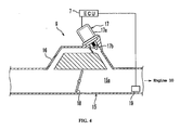
- FIG. 4 is a cross-sectional view illustrating components in the vicinity of an air intake pipe 15 connected to the engine 10.
- the air intake pipe 15 supplies the engine 10 with air.
- a throttle valve 18 as an air intake pipe valve is located in the air intake pipe 15.
- the throttle valve 18 adjusts the amount of air flowing in the air intake pipe 15 by adjusting the area of an air passage in the air intake pipe 15.
- the throttle valve 18 is operated by a throttle (not shown). As the throttle is opened, the throttle valve 18 is opened to increase the amount of air flowing in the air intake pipe 15.
- a throttle opening degree sensor 18a (refer to FIG. 5 ) is attached to the throttle valve 18.
- the opening degree of the throttle valve 18 is detected by the throttle opening degree sensor 18a.
- An air intake pipe pressure sensor 19 is located in the air intake pipe 15. Specifically, the air intake pipe pressure sensor 19 is located in a downstream section 15a of the air intake pipe 15 on the engine 10 side with respect to the throttle valve 18. The pressure of the downstream section 15a is detected by the air intake pipe pressure sensor 19. As shown in FIG. 5 , the air intake pipe pressure sensor 19 outputs to an ECU 7the pressure of the downstream section 15a as intake pipe pressure.
- An ISC device 9 which adjusts the rotational speed of the engine at a time of idling of the two-wheeled motorized vehicle 1 by adjusting the amount of air flowing in the air intake pipe 15 is attached to the air intake pipe 15.
- the ISC device 9 is constituted by a by-pass pipe 16, an air quantity adjusting device 17, and the ECU 7.
- the by-pass pipe 16 bypasses a section of the air intake pipe 15 in which the throttle valve 18 is located.
- the by-pass pipe 16 connects the upstream side and the downstream side of the air intake pipe 15 with respect to the throttle valve 18.
- the air quantity adjusting device 17 adjusts the amount of air flowing in the air intake pipe 15 by adjusting an area of an air passage in the by-pass pipe 16.
- the air quantity adjusting device 17 is provided with an actuator 17a and a by-pass pipe valve 17b actuated by the actuator 17a.
- the by-pass pipe valve 17b is located in the by-pass pipe 16.
- the by-pass pipe valve 17b adjusts the amount of air flowing in the by-pass pipe 16 by adjusting an area of an air passage in the by-pass pipe 16.
- the actuator 17a can be constituted, for example, by a stepper motor or the like.
- the transmission 20 is a belt type ECVT.
- the transmission 20, however, is not limited to a belt type ECVT.
- the transmission 20 may be, for example, a toroidal type ECVT .
- the transmission 20 is provided with a primary sheave 21, a secondary sheave 22, and a V-belt 23.
- the V-belt 23 is wrapped around the primary sheave 21 and the secondary sheave 22.
- the V-belt may be of any suitable form, and may be a rubber belt type, resin block belt type, or the like.
- the primary sheave 21 rotates together with the crankshaft 11.
- the primary sheave 21 includes a fixed sheave half 21a and a movable sheave half 21b.
- the fixed sheave half 21a is fixed to one end of the crankshaft 11.
- the movable sheave half 21b is located opposed to the fixed sheave half 21a.
- the movable sheave half 21b is movable in the axial direction of the crankshaft 11.
- One surface of the fixed sheave half 21a and one surface of the movable sheave half 21b are opposed to each other, which form a belt groove 21c into which the V-belt 23 is wrapped. As shown in FIG.
- the movable sheave half 21b has a boss section 21d in a cylindrical shape through which the crankshaft 11 penetrates.
- a slider 24 in a cylindrical shape is fixed in the boss section 21d.
- the movable sheave half 21b integral with the slider 24 is movable in the axial direction of the crankshaft 11. Accordingly, the width of the belt groove 21c may varied.
- the width of the belt groove 21c of the primary sheave 21 is varied as the movable sheave half 21b is driven in the axial direction of the crankshaft 11 by an electric motor 30.
- the electric motor 30 may be also used as a starter motor.
- the secondary sheave 22 is located rearward of the primary sheave 21.
- the secondary sheave 22 is mounted to a driven shaft 27 via a centrifugal clutch 25.
- the secondary sheave 22 includes a fixed sheave half 22a and a movable sheave half 22b.
- the movable sheave half 22b is opposed to the fixed sheave half 22a.
- the fixed sheave half 22a is connected to the driven shaft 27 via the centrifugal clutch 25.
- the movable sheave half 22b is movable in the axial direction of the driven shaft 27.
- One surface of the fixed sheave half 22a and one surface of the movable sheave half 22b are opposed to each other, which form a belt groove 22c into which the V-belt 23 is wrapped.
- the movable sheave half 22b is urged by a spring 26 in a direction to decrease the width of the belt groove 22c. Consequently, the width of the belt groove 21c of the primary sheave 21 becomes small, and the winding diameter of the V-belt 23 around the primary sheave 21 becomes large. As a result, the V-belt 23 is pulled inward in the radial direction on the side of the secondary sheave 22. Thus, the movable sheave half 22b moves against the urging force of the spring 26 in a direction to increase the width of the belt groove 22c. Therefore, the diameter with which the V-belt 23 is wrapped around the secondary sheave 22 decreases.
- the centrifugal clutch 25 is provided with a centrifugal plate 25a, a centrifugal weight 25b, and a clutch housing 25c.
- the centrifugal plate 25a rotates together with the fixed sheave half 22a.
- the centrifugal weight 25b is supported by the centrifugal plate 25a such that it is displaceable in the radial direction of the centrifugal plate 25a.
- a first clutch member 25d is constituted by the centrifugal plate 25a and the centrifugal weight 25b.
- An output shaft 22a1 of the transmission 20 is formed integrally on the fixed sheave half 22a of the secondary sheave 22.
- the output shaft 22a1 of the transmission 20 is constituted by a cylindrical section of the fixed sheave half 22a in which the driven shaft 27 is inserted.
- a second clutch member 25e is constituted by the clutch housing 25c.
- the clutch housing 25c is fixed to one end of the driven shaft 27.
- a speed reducing mechanism 28 is connected to the driven shaft 27.
- the driven shaft 27 is connected to an axle 29 via the speed reducing mechanism 28.
- the rear wheel 3 is mounted to the axle 29. Therefore, the clutch housing 25c is connected to the drive wheel or the rear wheel 3 via the driven shaft 27, the speed reducing mechanism 28 and the axle 29.
- the clutch housing 25c is engaged with and disengaged from the first clutch member 25d according to the rotational speed of the output shaft 22a1.
- the centrifugal weight 25b is moved outward in the radial direction of the centrifugal plate 25a by centrifugal force and comes in contact with the clutch housing 25c.
- the first clutch member 25d is engaged with the clutch housing 25c as the second clutch member 25e.
- the rotation of the output shaft 22a1 is transmitted to the rear wheel 3 as the drive wheel via the clutch housing 25c, the driven shaft 27, the speed reducing mechanism 28, and the axle 29.
- the two-wheeled motorized vehicle 1 has the ECU 7 as a controller.
- the transmission 20, the engine 10, and so forth are controlled by the ECU 7.
- a sheave position sensor 40 is connected to the ECU 7.
- a transmission gear ratio sensor for detecting the transmission gear ratio of the transmission 20 is constituted by the sheave position sensor 40.
- the sheave position sensor 40 is, as it were, the sensor for detecting the state of a movable section of the transmission 20.
- the sheave position sensor 40 detects the transmission gear ratio of the transmission 20 by detecting the state of the movable section of the transmission 20.
- the sheave position sensor 40 detects the position of the movable sheave half 21b of the primary sheave 21.
- the sheave position sensor 40 outputs the detected position of the movable sheave half 21b as a sheave position detection signal to the ECU 7.
- the sheave position sensor 40 may be formed by a potentiometer, for example.
- a primary sheave rotation sensor 43 detects the rotational speed of the primary sheave 21.
- the primary sheave rotation sensor 43 outputs a primary sheave rotational speed signal to the ECU 7 on the basis of the detected rotational speed of the primary sheave 21.
- the secondary sheave rotation sensor 41 detects a rotational speed of the secondary sheave 22.
- the secondary sheave rotation sensor 41 outputs a secondary sheave rotational speed signal to the ECU 7 on the basis of the detected rotational speed of the secondary sheave 22.
- the vehicle speed sensor 42 detects the rotational speed of the rear wheel 3.
- the vehicle speed sensor 42 outputs to the ECU 7 a vehicle speed signal based on the detected rotational speed.
- a handlebar switch attached to the steering handlebars 4 is connected to the ECU 7.
- the handlebar switch outputs a handlebar SW signal when a rider operates the handlebar switch.
- a throttle opening sensor 18a outputs a throttle opening signal to the ECU 7.
- the ECU 7 controls the sheave position of the movable sheave half 21b of the primary sheave 21 on the basis of the vehicle speed signal output from the vehicle speed sensor 42. Specifically, a target transmission gear ratio is decided depending on the throttle opening degree and the vehicle speed in the ECU 7. The ECU 7 calculates a target sheave position based on the determined target change-gear ratio. The sheave position of the movable sheave half 21b of the primary sheave 21 is controlled according to the calculated sheave target position.
- the driving system of the electric motor 30 is not specifically limited.
- the electric motor 30 is driven by a pulse width modulation (PWM) drive.
- the ECU 7 is provided with a drive circuit (not shown) for the electric motor 30 and a CPU (central processing unit) (not shown) for outputting a signal to the drive circuit.
- the CPU outputs a pulse width modulation signal to the drive circuit.
- the drive circuit applies the pulse voltage in accordance with the pulse width modulation signal to the electric motor 30.
- the electric motor 30 is thus driven.
- the electric motor 30 may be a stepper motor type or the like.
- the idle speed control (ISC) feed back control (hereafter referred to as "ISC F/B") is a control for changing the engine rotational speed of the engine 10 in the idling state.
- the ISC F/B is the control which, for example, increases the idle rotational speed in order to warm up the two-wheeled motorized vehicle 1 promptly at a time of idling.
- step S21 the ISC F/B control is performed according to the flow chart shown in FIG. 6 in the embodiment. Whether the following conditions 1) to 6) are satisfied is judged in step S21 first. If the following conditions 1) to 6) are judged to be satisfied in step S21, the procedure proceeds to step S22 where the amount of intake air to the engine 10 is adjusted. Specifically, the amount of intake air to the engine 10 is increased or decreased. For instance, if the amount of intake air to the engine 10 is to be increased, the by-pass pipe valve 17b is actuated by the actuator 17a, the air passage area in the by-pass pipe 16 is expanded, and the amount of intake air to the engine 10 is increased.
- step S21 if the following conditions 1) to 6) are judged not to be satisfied in step S21, the procedure returns to step S21 again.
- Conditions 1) and 2) in step S21 are the conditions to avoid the engine 10 from stopping.
- the engine rotational speed enabling the ISC F/B control in condition 1) can be set, for example, to 500 rpm.
- the engine rotational speed enabling the ISC F/B control in condition 1) and the water temperature enabling the ISC F/B control in condition 2) can be appropriately set according to the type of the two-wheeled motorized vehicle 1, the use environment thereof, and so forth.
- Conditions 3) and 4) in step S21 are the conditions to judge whether or not the two-wheeled motorized vehicle 1 is in a state of idling with vehicle speed not very high.
- the idling judgment opening degree in condition 3) and the vehicle speed enabling the ISC F/B control in condition 4) can be also appropriately set according to the type of the two-wheeled motorized vehicle 1, the use environment thereof, and so forth.
- step S21 is the condition to judge whether or not fuel has already been cut for deceleration as a result of any control other than the ISC F/B control.
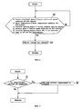
- the ISC F/B control described above is suppressed or stopped on the basis of the flow chart shown in FIG. 7 . Specifically, the ISC F/B control is suppressed or stopped when the centrifugal clutch 25 is engaged.
- step S1 whether or not the centrifugal clutch 25 is engaged is judged in step S1. Specifically, whether or not the first clutch member 25d and the second clutch member 25e are engaged is judged in step S1.
- the method for judging whether or not the centrifugal clutch 25 is engaged is not limited to any specific method. For instance, whether or not the centrifugal clutch 25 is engaged may be judged depending on the rotational speed of the first clutch member 25d detected by the secondary sheave rotation sensor 41. Specifically, it is possible to judge that the centrifugal clutch 25 is engaged when the rotational speed of the first clutch member 25d and the driven shaft 27 is equal to or higher than a predefined rotational speed.
- centrifugal clutch 25 may be judged depending on the amount of difference between the rotational speed of the first clutch member 25d and the driven shaft 27 and the rotational speed of the second clutch member 25e. Specifically, it is possible to judge that the centrifugal clutch 25 is engaged when the rotational speed of the first clutch member 25d and the driven shaft 27 is practically equal to the rotational speed of the second clutch member 25e.
- step S1 If it is judged in step S1 that the centrifugal clutch 25 is engaged, the ISC F/B control is suppressed or stopped. In order to suppress the ISC F/B control, the gain of the ISC F/B control may be decreased, or the feedback frequency of the ISC F/B feedback control may be reduced.
- the speed of the two-wheeled motorized vehicle 1 may be increased regardless of the fact that the throttle is closed. This happens when the centrifugal clutch 25 is engaged. When the centrifugal clutch 25 is not engaged, the power of the engine 10 is not transmitted to the rear wheel 3. Accordingly, the speed of the two-wheeled motorized vehicle 1 is not increased while the throttle is closed.
- the ISC F/B control is suppressed or stopped when the centrifugal clutch 25 is engaged. As a result, the embodiment avoids the state in which the speed of the two-wheeled motorized vehicle 1 is increased against the rider's intention. Therefore, excellent drivability is achieved.
- the ISC F/B control is the control which adjusts the rotational speed of the engine at a time of idling of the two-wheeled motorized vehicle 1. Therefore, the ISC F/B control is not necessary in particular when the rotational speed of the engine is relatively high so that the centrifugal clutch 25 is engaged. Accordingly, problems as minimized even if the ISC F/B control is suppressed or stopped while the centrifugal clutch 25 is engaged.
- ISC F/B control may or may not be performed while the centrifugal clutch 25 is in the half-clutch state.
- the ISC F/B control is suppressed or stopped when the centrifugal clutch 25 is engaged is described with reference to the embodiment above.
- the present invention is not limited to the embodiment above.
- the ISC F/B control may be suppressed or stopped when abnormality occurs in the transmission 20 as described below.
- Suppressing and stopping the ISC F/B control in a first modified example will be described hereinafter with reference to FIG. 8 . Operations other than suppressing and stopping the ISC F/B control are the same as those in the embodiment above, and FIGs. 1 to 6 are also referred to.
- step S11 whether or not abnormality in the transmission 20 has occurred is judged in step S11.
- step S11 that abnormality has occurred in the transmission 20
- the procedure proceeds to step S12, and the ISC F/B control is suppressed or stopped.
- Suppressing or stopping the ISC F/B control performed in step S12 is the same as suppressing and stopping the ISC F/B control performed in step S2.
- the “abnormality in the transmission 20” indicates that the control of the transmission gear ratio is not performed as usual in the transmission 20.
- the “abnormality in the transmission 20” includes a case in which at least one of abnormality in the primary sheave rotation sensor 43 as the input shaft rotational speed sensor, abnormality in the throttle opening degree sensor 18a, abnormality in the vehicle speed sensor 42, abnormality in a transmission mechanism of the transmission 20 excluding the ECU 7, abnormality in the transmission control system including the ECU 7, wiring connecting the ECU 7 and the transmission mechanism, and so forth, abnormality in the sheave position senor 40 as the transmission gear ratio sensor, abnormality in the secondary sheave rotation sensor 41, and the so forth has occurred.
- the transmission gear ratio of the transmission 20 may be kept relatively high regardless of the fact that the throttle is closed when, for example, abnormality has occurred in the transmission 20. Therefore, an occurrence of a state in which the speed of the vehicle is increased against the rider's intention can be avoided by suppressing or stopping the ISC F/B control when abnormality has occurred in the transmission 20.
- the ISC device 9 in the present invention is not limited to the ISC device having the by-pass pipe.
- the ISC device 9 may be, for example, an ISC device in which a throttle valve 18b of an electronic control type actuated by an actuator 45 is used, as shown in FIG. 9 .
- the opening degree of the throttle valve 18b is electronically controlled by the ECU 7.
- the ISC device 9 may be constituted by a throttle opening degree adjusting device 50 for forcibly adjusting the opening degree of the throttle valve 18 of a non-electronic control type and the ECU 7.
- the throttle opening degree adjusting device 50 may be constituted by, for example, a pressing member 52 for pressing the throttle valve 18 and an actuator 51 for actuating the pressing member 52.
- the throttle opening degree adjusting device 50 may be constituted by, for example, a solenoid element.
- the centrifugal clutch 25 of the embodiment first described above is located between the output shaft 22a1 and the rear wheel 3.
- the centrifugal clutch 25 only has to be located in the power transmission path between the engine 10 and the rear wheel 3.
- the centrifugal clutch 25 may be located between the crankshaft 11 as an input shaft and the primary sheave 21.
- the centrifugal clutch 25 does not have to be engaged or disengaged according to the rotational speed of the output shaft 22a1, but may be engaged or disengaged according to the rotational speed of the crankshaft 11 as an input shaft.
- FIG. 11 is a block diagram illustrating a system for controlling a two-wheeled motorized vehicle in accordance with a further embodiment of the present invention.
- variable transmission 260 is a belt type ECVT.
- the belt of the variable transmission 260 in accordance with the embodiment 2 is a so-called metal belt 264.
- the actuator of ECVT in the first described embodiment is the electric motor 30.
- the actuator of ECVT is not limited to the electric motor 30.
- the actuator of ECVT in the present embodiment, described below, is a hydraulic actuator.
- a clutch in the first described embodiment is the centrifugal clutch 25 which is mechanically engaged or disengaged according to the rotational speed of the output shaft 22a1 of the transmission mechanism 20.
- any type of clutch is acceptable as long as it is engaged or disengaged according to the rotational speed of the input shaft or output shaft of the transmission mechanism.
- a clutch does not have to be engaged or disengaged mechanically according to the rotational speed.
- a clutch may be controlled to be engaged or disengaged according the rotational speed.
- an electrically controlled multiple friction clutch 265 is used.
- a two-wheeled motorized vehicle includes the electrically controlled multiple friction clutch 265 and the ECVT type variable transmission 260.
- the variable transmission 260 includes a primary sheave 262, a secondary sheave 263, and the metal belt 264 wound around the primary sheave 262 and the secondary sheave 263.
- the primary sheave 262 includes a fixed sheave half 262A and a movable sheave half 262B.
- the secondary sheave 263 includes a fixed sheave half 263A and a movable sheave half 263B.
- a primary sheave rotation sensor 43 is equipped to the primary sheave 262.
- a secondary sheave rotation sensor 41 is equipped to the secondary sheave 263.
- the two-wheeled motorized vehicle includes a hydraulic cylinder 267A, a hydraulic cylinder 267B, and a hydraulic control valve 267C connected to the hydraulic cylinder 267A and 267B.
- the hydraulic cylinder 267A adjusts the groove width of the primary sheave 262 by driving the movable sheave half 262B of the primary sheave 262.
- the hydraulic cylinder 267B adjusts the groove width of the secondary sheave 263 by driving the movable sheave half 263B of the secondary sheave 263.
- the hydraulic control valve 267C is a valve that adjusts the hydraulic pressure applied to the hydraulic cylinder 267A and 267B.
- the hydraulic control valve 267C controls the hydraulic cylinder 267A and 267B in the way when either one of them has higher hydraulic pressure the other one has lower hydraulic pressure. This hydraulic control valve 267C is controlled by ECU7.
- the multiple friction clutch 265 is located between the engine 10 and the input shaft 271 of the variable transmission 260, and controlled depending on the rotational speed of the engine 10. For example, the multiple friction clutch 265 is controlled in such a way that it is connected when the speed of the engine 10 exceeds the predetermined value or higher and it is disconnected when the speed of the engine 10 is below the predetermined value.
- ISC F/B control is suppressed or stopped when the multiple friction clutch 265 is engaged (See FIG. 7 ).
- the abnormality of the transmission 260 is detected, and if the abnormality occurs, ISC F/B control is suppressed or stopped (See FIG. 8 ).
- ISC F/B control may or may not be performed while the multiple friction clutch 265 is in the half clutch state.
- the vehicle in the present invention may be a two-wheeled motorized vehicle other than a scooter-type vehicle.
- the vehicle of the present invention may be a two-wheeled motorized vehicle of an off-road type, a motorcycle type, a scooter type, or a so-called moped type.
- the vehicle in the invention may be a straddle-type vehicle.
- the vehicle of the present invention may be, for example, an ATV (All Terrain Vehicle) or the like.
- the vehicle in the invention may be a vehicle other than straddle type vehicle, such as a four-wheeled motorized vehicle.
- the transmission may be, for example, an ECVT of a toroidal type.
- the engine 10 may be an engine of a type other than a four-cycle engine of a forced air cooling type.
- the engine 10 may be a water-cooled engine, oil-cooled engine or the like.
- the engine 10 may be a two-stroke engine, for example.
- the conditions for the ISC F/B control may be different from those shown in FIG. 6 .
- the conditions for the ISC F/B control can be appropriately decided depending on a vehicle type or the like.
- the "idle rotational speed” indicates the rotational speed of the engine at a time of idling of the vehicle.
- “Suppressing the ISC F/B control” indicates decreasing the gain of the ISC F/B control or increasing the feedback frequency of the ISC F/B control.
- the “abnormality in the transmission” indicates that the control of the transmission gear ratio is not performed as usual in the transmission.
- the “abnormality in the transmission” may include a case in which at least one of abnormality in the primary sheave rotation sensor 43 as the input shaft rotational speed sensor, abnormality in the throttle opening degree sensor 18a, abnormality in the vehicle speed sensor 42, abnormality in a transmission mechanism of the transmission 20 excluding the ECU 7, abnormality in the transmission control system including the ECU 7, wiring connecting the ECU 7 and the transmission mechanism, and so forth, abnormality in the sheave position senor 40 as the transmission gear ratio sensor, abnormality in the secondary sheave rotation sensor 41, and the so forth has occurred.
- the "state in which the clutch is engaged” may or may not include the state in which the clutch is half engaged depending on a vehicle to which the present invention is applied.
- “Clutch engaged or disengaged according to the rotational speed” includes a clutch that is controlled to be engaged or disengaged according to the rotational speed along with the centrifugal clutch that is mechanically engaged or disengaged according to the rotational speed.
- the present invention is useful for a vehicle such as a straddle-type vehicle and the like.
Abstract
Description
- The present invention relates to a vehicle, and a control device and a control method thereof. In particular, the present invention relates to a vehicle having an electronic continuously variable transmission and an idle speed control device, and a control device, and a control method thereof.
- Continuously variable transmissions (hereinafter referred to as "CVT") that perform idle speed control (ISC) are known, for example, from
JP-A-2004-19740 - Electronic continuously variable transmissions (hereinafter referred to as "ECVT") are also known. In an ECVT, the transmission gear ratio can be adjusted regardless of the rotational speed of the engine. Therefore, the ECVT is widely used for vehicles such as scooters.
- When the ISC disclosed in
JP-A-2004-19740 - The present invention has been made in view of the situation described above, and has an object to improve drivability of a vehicle provided with an ECVT and an idle speed control device.
- A vehicle according to an aspect of the present invention includes: a drive wheel; an engine; an electronic continuously variable transmission having an input shaft connected to the engine and an output shaft to adjust a transmission gear ratio between the input shaft and the output shaft; a clutch located in the power transmission path between the engine and the drive wheel to be engaged and disengaged according to a rotational speed of the input shaft or output shaft; an idle speed control device for performing idle speed control to adjust an idle rotational speed of the engine; and a control unit for suppressing or stopping the idle speed control when the clutch is engaged.
- A vehicle according to another aspect of the present invention includes: a drive wheel; an engine; an electronic continuously variable transmission having an input shaft connected to the engine and an output shaft to adjust a transmission gear ratio between the input shaft and the output shaft; a clutch located between the output shaft and the drive wheel to be engaged and disengaged according to a rotational speed of the output shaft; an idle speed control device for performing idle speed control to adjust an idle rotational speed of the engine; and a control unit for suppressing or stopping the idle speed control when the clutch is engaged.
- A vehicle according to a further aspect of the present invention includes: a drive wheel; an engine; an electronic continuously variable transmission having an input shaft connected to the engine and an output shaft to adjust a transmission gear ratio between the input shaft and the output shaft; a clutch located in the power transmission path between the engine and the drive wheel to be engaged and disengaged according to a rotational speed of the input shaft or output shaft; an idle speed control device for performing idle speed control to adjust an idle rotational speed of the engine; and a control unit for detecting the abnormality in the continuously variable transmission, and suppressing or stopping the idle speed control when the abnormality is detected in the continuously variable transmission.
- A vehicle according to a still further aspect of the present invention includes: a drive wheel; an engine; an electronic continuously variable transmission having an input shaft connected to the engine and an output shaft to adjust a transmission gear ratio between the input shaft and the output shaft; a clutch located in between the engine and the drive wheel to be engaged and disengaged according to a rotational speed of the input shaft or output shaft; an idle speed control device for performing idle speed control to adjust an idle rotational speed of the engine; and a control unit for detecting the abnormality in the continuously variable transmission, and suppressing or stopping the idle speed control when the abnormality is detected in the continuously variable transmission.
- A controller for a vehicle according to a further aspect of the present invention is a controller for suppressing or stopping the idle speed control when the clutch is engaged. The vehicle includes: a drive wheel; an engine; an electronic continuously variable transmission having an input shaft connected to the engine and an output shaft to adjust a transmission gear ratio between the input shaft and the output shaft; a clutch located in the power transmission path between the engine and the drive wheel to be engaged and disengaged according to a rotational speed of the input shaft or output shaft; an idle speed control device for performing idle speed control to adjust an idle rotational speed of the engine.
- A controller for a vehicle according to another aspect of the present invention is a controller that suppresses or stops the idle speed when the clutch is engaged. The vehicle includes: a drive wheel; an engine; an electronic continuously variable transmission having an input shaft connected to the engine and an output shaft to adjust a transmission gear ratio between the input shaft and the output shaft; a clutch located between the output shaft and the drive wheel to be engaged and disengaged according to a rotational speed of the output shaft; and an idle speed control device for performing idle speed control to adjust an idle rotational speed of the engine.
- A controller for a vehicle according to a further aspect of the present invention detects the abnormality of a continuously variable transmission. When the controller detects the abnormality in the continuously variable transmission, the controller suppresses or stops an idle speed control. The vehicle includes: a drive wheel; an engine; an electronic continuously variable transmission having an input shaft connected to the engine and an output shaft to adjust a transmission gear ratio between the input shaft and the output shaft; a clutch located in the power transmission path between the engine and the drive wheel to be engaged and disengaged according to a rotational speed of the input shaft or output shaft; an idle speed control device for performing idle speed control to adjust an idle rotational speed of the engine.
- A controller for a vehicle according to a further aspect of the present invention detects the abnormality of a continuously variable transmission. When the controller detects the abnormality in the continuously variable transmission, the controller suppresses or stops an idle speed control. The vehicle includes: a drive wheel; an engine; an electronic continuously variable transmission having an input shaft connected to the engine and an output shaft to adjust a transmission gear ratio between the input shaft and the output shaft; a clutch located between the output shaft and the drive wheel to be engaged and disengaged according to a rotational speed of the output shaft; and an idle speed control device for performing idle speed control to adjust an idle rotational speed of the engine.
- A control method for a vehicle according to another aspect of the present invention is a method to suppress or stop an idle speed control when a clutch is engaged. The vehicle includes: a drive wheel; an engine; an electronic continuously variable transmission having an input shaft connected to the engine and an output shaft to adjust a transmission gear ratio between the input shaft and the output shaft; a clutch located in the power transmission path between the engine and the drive wheel to be engaged and disengaged according to a rotational speed of the input shaft or output shaft; an idle speed control device for performing idle speed control to adjust an idle rotational speed of the engine.
- A control method for a vehicle according to a further aspect of the present invention is a method to suppress or stop an idle speed control. The vehicle includes: a drive wheel; an engine; an electronic continuously variable transmission having an input shaft connected to the engine and an output shaft to adjust a transmission gear ratio between the input shaft and the output shaft; a clutch located between the output shaft and the drive wheel to be engaged and disengaged according to a rotational speed of the output shaft; and an idle speed control device for performing idle speed control to adjust an idle rotational speed of the engine.
- A control method for a vehicle according to a further aspect of the present invention is a method to detect the abnormality of a continuously variable transmission and to suppress or stop an idle speed control when the abnormality is detected. The vehicle includes: a drive wheel; an engine; an electronic continuously variable transmission having an input shaft connected to the engine and an output shaft to adjust a transmission gear ratio between the input shaft and the output shaft; a clutch located in the power transmission path between the engine and the drive wheel to be engaged and disengaged according to a rotational speed of the input shaft or output shaft; an idle speed control device for performing idle speed control to adjust an idle rotational speed of the engine.
- A control method for a vehicle according to another aspect of the present invention is a method to detect the abnormality of a continuously variable transmission and to suppress or stop an idle speed control when the abnormality is detected. The vehicle includes: a drive wheel; an engine; an electronic continuously variable transmission having an input shaft connected to the engine and an output shaft to adjust a transmission gear ratio between the input shaft and the output shaft; a clutch located between the output shaft and the drive wheel to be engaged and disengaged according to a rotational speed of the output shaft; and an idle speed control device for performing idle speed control to adjust an idle rotational speed of the engine.
- According to a further aspect of the present invention there is provided a vehicle comprising:
- a drive wheel;
- an engine;
- an electronic continuously variable transmission having an input shaft and an output shaft;
- a clutch;
- an idle speed control device for performing idle speed control to adjust an idle rotational speed of the engine; and
- a control unit for suppressing or stopping the idle speed control when at least one of the clutch is engaged and the control unit detects an abnormality in the continuously variable transmission.
- The clutch may be located in a power transmission between the engine and the drive wheel and may be adapted to be engaged or disengaged according to the rotational speed of the input shaft or the output shaft.
- The clutch may be located between the output shaft and the drive wheel and may be adapted to be engaged or disengaged according to the rotational speed of the output shaft.
- The clutch may include a first clutch member connected directly or indirectly to the output shaft, and a second clutch member connected directly or indirectly to the drive wheel. The second clutch member may be adapted to be engaged with or disengaged with the first clutch member according to the rotational speed of the output shaft. The control unit may determine an engaged or disengaged state of the clutch based on the rotational speed of the first clutch member or based on the difference of the rotational speed between the first clutch member and the second clutch member.
- The vehicle may further comprise:
- an input shaft rotational speed sensor for detecting the rotational speed of the input shaft;
- a throttle opening degree sensor; and
- a vehicle speed sensor;
- According to a further aspect of the present invention there is provided a controller for a vehicle, said vehicle comprising:
- a drive wheel;
- an engine;
- an electronic continuously variable transmission having an input shaft and an output shaft;
- a clutch; and
- an idle speed control device for performing idle speed control to adjust an idle rotational speed of the engine;
- The clutch may be located in a power transmission between the engine and the drive wheel and may be adapted to be engaged or disengaged according to the rotational speed of the input shaft or the output shaft.
- The clutch may be located between the output shaft and the drive wheel and may be adapted to be engaged or disengaged according to the rotational speed of the output shaft.
- According to a further aspect of the present invention there is provided a control method for a vehicle, said vehicle comprising:
- a drive wheel;
- an engine;
- an electronic continuously variable transmission having an input shaft and an output shaft;
- a clutch; and
- an idle speed control device for performing idle speed control to adjust an idle rotational speed of the engine;
- The clutch may be located in a power transmission between the engine and the drive wheel and may be adapted to be engaged or disengaged according to the rotational speed of the input shaft or the output shaft.
- The clutch may be located between the output shaft and the drive wheel and may be adapted to be engaged or disengaged according to the rotational speed of the output shaft.
- The input shaft of the continuously variable transmission may be connected to the engine, and the transmission is preferably adapted to adjust a gear ratio between the input shaft and the output shaft.
- The present invention will improve the drivability of a vehicle provided with an ECVT and an idle speed control device.
- These and other aspect of the present invention will now be described, by way of example only, with reference to the accompanying drawings, in which:
-
FIG. 1 is a side view of a two-wheeled motorized vehicle in accordance with a first embodiment of the present invention; -
FIG. 2 is a sectional view of an engine unit; -
FIG. 3 is a partial cross-sectional view illustrating the constitution of a CVT; -
FIG. 4 is a cross-sectional view illustrating components in the vicinity of an air intake pipe of an engine; -
FIG. 5 is a block diagram illustrating a system for controlling the two-wheeled motorized vehicle; -
FIG. 6 is a flow chart illustrating the ISC F/B control; -
FIG. 7 is a flow chart illustrating the control to suppress or stop the ISC F/B control on the basis of the state of the engagement of the centrifugal clutch; -
FIG. 8 is a flow chart illustrating the control to suppress or stop the ISC F/B control on the basis of abnormality in the transmission in a modified example of the first embodiment; -
FIG. 9 is a cross-sectional view illustrating components in the vicinity of an air intake pipe of an engine in another modified example of the first embodiment; -
FIG. 10 is a cross-sectional view illustrating components in the vicinity of an air intake pipe of an engine in a further modified example of the first embodiment; and -
FIG. 11 is a block diagram illustrating a control system in accordance with a second embodiment of the present invention. - As a result of strenuous research, the inventors of the present invention have found the reason why a vehicle increases speed while the throttle is closed for the first time ever, and the inventors have made an embodiment described below. Before a vehicle according to an embodiment of the present invention is described in detail, the reason why a vehicle increases speed while the throttle is closed, which has been found by the inventors, will be described.
- For example, in a case of a CVT using a centrifugal weight, the transmission gear ratio is decided according to the rotational speed of an engine. Specifically, when the rotational speed of the engine is relatively high, the transmission gear ratio becomes relatively small. On the other hand, when the rotational speed of the engine is relatively low, the transmission gear ratio becomes relatively large. In a vehicle provided with an ECVT, however, the transmission gear ratio can be changed regardless of the rotational speed of an
engine 10 as described above. Accordingly, there can be a situation in which the transmission gear ratio is small even when the rotational speed of the engine is low. - When the transmission gear ratio is small, the rotational speed of the output shaft of the ECVT becomes relatively high. Accordingly, when the transmission gear ratio is small, the rotational speed of the output shaft of the ECVT becomes relatively high regardless of the fact that the rotational speed of the engine is low. As a result, a state can be generated in which a centrifugal clutch attached to the output shaft is not disengaged. In other words, there can be a situation in which the centrifugal clutch is kept engaged regardless of the fact that the rotational speed of the engine is low.
- Further, when the transmission gear ratio is small, the load on the engine becomes relatively large. Therefore, the rotational speed of the engine becomes lower than a target rotational speed. Accordingly, the ISC is activated to increase the rotational speed of the engine.
- As described above, when the transmission gear ratio is kept small, the ISC may be actuated with the centrifugal clutch kept engaged, even if the rotational speed of the engine is low. Accordingly, even when the rider closes the throttle in order to decrease speed of the vehicle provided with the ECVT, the ISC may be activated to problematically increase speed of the vehicle, because of the transmission gear ratio is relatively small. The inventors have found the fact described above for the first time ever, and the inventors have made an embodiment described below.
- An embodiment of the present invention will be hereinafter described in detail, using a two-wheeled
motorized vehicle 1 shown inFIG. 1 . The embodiment of the present invention is described by using a so-called scooter-type two-wheeledmotorized vehicle 1 as an example. However, a vehicle according to the invention is not limited to the so-called scooter-type two-wheeled motorized vehicle. For example, the vehicle in the present invention may be a two-wheeled motorized vehicle other than scooter-type vehicle. Specifically, the vehicle of the present invention may be a two-wheeled motorized vehicle of an off-road type, a motorcycle type, a scooter type, or a so-called moped type. Also, other than a two-wheeled motorized vehicle, the vehicle in the invention may be a straddle-type vehicle. Specifically, the vehicle of the present invention may be, for example, an ATV (All Terrain Vehicle) or the like. Further, the vehicle in the invention may be a vehicle other than straddle type vehicle, such as a four-wheeled motorized vehicle. - Further, the two-wheeled
motorized vehicle 1 provided with a belt type ECVT will be described as an example in the present embodiment. The vehicle according to the present invention, however, is not limited to the vehicle constituted as described above. For example, the vehicle according to the present invention may be a vehicle having an ECVT of a type other than the belt type. The vehicle according to the present invention may be, for example, a vehicle having an ECVT of a toroidal type or the like. -
FIG. 1 shows a side view of a two-wheeledmotorized vehicle 1. The two-wheeledmotorized vehicle 1 has a body frame (not shown). Anengine unit 2 is suspended from the body frame. A rear wheel 3 is provided at a rear end of theengine unit 2. In the embodiment of the invention, the rear wheel 3 forms a drive wheel for driving a wheel with power outputted from theengine unit 2. - The body frame has a head pipe (not shown) extending downward from steering handlebars 4. Front forks 5 are connected to a bottom end of the head pipe. A front wheel 6 is rotatably attached to lower ends of the front forks 5. The front wheel 6, which is not drivingly connected to the
engine unit 2, forms a driven wheel. - The constitution of the
engine unit 2 will now be described with reference toFIG. 2 to FIG. 4 . - As shown in
FIG. 2 andFIG. 3 , theengine unit 2 has an engine (internal combustion engine) 10 and atransmission 20. In the embodiment of the invention, theengine 10 is described as a forced-air-cooled four-stroke engine. However, theengine 10 may be any other suitable type of engine. For example, theengine 10 may be a water-cooled engine, oil-cooled engine or the like. Theengine 10 may be a two-stroke engine, for example. - As shown in
FIG. 3 , theengine 10 has acrankshaft 11. Asleeve 12 is spline-fitted onto an outer circumference of thecrankshaft 11. Thesleeve 12 is rotatably supported by ahousing 14 via abearing 13. A one-way clutch 31 connected to anelectric motor 30 is attached to the outer circumference of thesleeve 12. -
FIG. 4 is a cross-sectional view illustrating components in the vicinity of anair intake pipe 15 connected to theengine 10. Theair intake pipe 15 supplies theengine 10 with air. Athrottle valve 18 as an air intake pipe valve is located in theair intake pipe 15. Thethrottle valve 18 adjusts the amount of air flowing in theair intake pipe 15 by adjusting the area of an air passage in theair intake pipe 15. Thethrottle valve 18 is operated by a throttle (not shown). As the throttle is opened, thethrottle valve 18 is opened to increase the amount of air flowing in theair intake pipe 15. - A throttle
opening degree sensor 18a (refer toFIG. 5 ) is attached to thethrottle valve 18. The opening degree of thethrottle valve 18 is detected by the throttleopening degree sensor 18a. - An air intake
pipe pressure sensor 19 is located in theair intake pipe 15. Specifically, the air intakepipe pressure sensor 19 is located in adownstream section 15a of theair intake pipe 15 on theengine 10 side with respect to thethrottle valve 18. The pressure of thedownstream section 15a is detected by the air intakepipe pressure sensor 19. As shown inFIG. 5 , the air intakepipe pressure sensor 19 outputs to an ECU 7the pressure of thedownstream section 15a as intake pipe pressure. - An ISC device 9 which adjusts the rotational speed of the engine at a time of idling of the two-wheeled
motorized vehicle 1 by adjusting the amount of air flowing in theair intake pipe 15 is attached to theair intake pipe 15. Specifically, the ISC device 9 is constituted by a by-pass pipe 16, an airquantity adjusting device 17, and theECU 7. The by-pass pipe 16 bypasses a section of theair intake pipe 15 in which thethrottle valve 18 is located. In other words, the by-pass pipe 16 connects the upstream side and the downstream side of theair intake pipe 15 with respect to thethrottle valve 18. The airquantity adjusting device 17 adjusts the amount of air flowing in theair intake pipe 15 by adjusting an area of an air passage in the by-pass pipe 16. Specifically, the airquantity adjusting device 17 is provided with anactuator 17a and a by-pass pipe valve 17b actuated by theactuator 17a. The by-pass pipe valve 17b is located in the by-pass pipe 16. The by-pass pipe valve 17b adjusts the amount of air flowing in the by-pass pipe 16 by adjusting an area of an air passage in the by-pass pipe 16. Theactuator 17a can be constituted, for example, by a stepper motor or the like. - In the present embodiment, the
transmission 20 is a belt type ECVT. Thetransmission 20, however, is not limited to a belt type ECVT. Thetransmission 20 may be, for example, a toroidal type ECVT . - As shown in
FIG. 2 andFIG. 3 , thetransmission 20 is provided with aprimary sheave 21, asecondary sheave 22, and a V-belt 23. The V-belt 23 is wrapped around theprimary sheave 21 and thesecondary sheave 22. The V-belt may be of any suitable form, and may be a rubber belt type, resin block belt type, or the like. - The
primary sheave 21 rotates together with thecrankshaft 11. Theprimary sheave 21 includes a fixedsheave half 21a and amovable sheave half 21b. The fixedsheave half 21a is fixed to one end of thecrankshaft 11. Themovable sheave half 21b is located opposed to the fixedsheave half 21a. Themovable sheave half 21b is movable in the axial direction of thecrankshaft 11. One surface of the fixedsheave half 21a and one surface of themovable sheave half 21b are opposed to each other, which form abelt groove 21c into which the V-belt 23 is wrapped. As shown inFIG. 3 , themovable sheave half 21b has aboss section 21d in a cylindrical shape through which thecrankshaft 11 penetrates. Aslider 24 in a cylindrical shape is fixed in theboss section 21d. Themovable sheave half 21b integral with theslider 24 is movable in the axial direction of thecrankshaft 11. Accordingly, the width of thebelt groove 21c may varied. - The width of the
belt groove 21c of theprimary sheave 21 is varied as themovable sheave half 21b is driven in the axial direction of thecrankshaft 11 by anelectric motor 30. Theelectric motor 30 may be also used as a starter motor. - The
secondary sheave 22 is located rearward of theprimary sheave 21. Thesecondary sheave 22 is mounted to a drivenshaft 27 via acentrifugal clutch 25. To be more specific, thesecondary sheave 22 includes a fixedsheave half 22a and amovable sheave half 22b. Themovable sheave half 22b is opposed to the fixedsheave half 22a. The fixedsheave half 22a is connected to the drivenshaft 27 via thecentrifugal clutch 25. Themovable sheave half 22b is movable in the axial direction of the drivenshaft 27. One surface of the fixedsheave half 22a and one surface of themovable sheave half 22b are opposed to each other, which form abelt groove 22c into which the V-belt 23 is wrapped. - The
movable sheave half 22b is urged by aspring 26 in a direction to decrease the width of thebelt groove 22c. Consequently, the width of thebelt groove 21c of theprimary sheave 21 becomes small, and the winding diameter of the V-belt 23 around theprimary sheave 21 becomes large. As a result, the V-belt 23 is pulled inward in the radial direction on the side of thesecondary sheave 22. Thus, themovable sheave half 22b moves against the urging force of thespring 26 in a direction to increase the width of thebelt groove 22c. Therefore, the diameter with which the V-belt 23 is wrapped around thesecondary sheave 22 decreases. - The centrifugal clutch 25 is provided with a
centrifugal plate 25a, acentrifugal weight 25b, and aclutch housing 25c. Thecentrifugal plate 25a rotates together with the fixedsheave half 22a. Thecentrifugal weight 25b is supported by thecentrifugal plate 25a such that it is displaceable in the radial direction of thecentrifugal plate 25a. - In the present embodiment, a first
clutch member 25d is constituted by thecentrifugal plate 25a and thecentrifugal weight 25b. An output shaft 22a1 of thetransmission 20 is formed integrally on the fixedsheave half 22a of thesecondary sheave 22. Specifically, the output shaft 22a1 of thetransmission 20 is constituted by a cylindrical section of the fixedsheave half 22a in which the drivenshaft 27 is inserted. - A second
clutch member 25e is constituted by theclutch housing 25c. Theclutch housing 25c is fixed to one end of the drivenshaft 27. Aspeed reducing mechanism 28 is connected to the drivenshaft 27. The drivenshaft 27 is connected to anaxle 29 via thespeed reducing mechanism 28. The rear wheel 3 is mounted to theaxle 29. Therefore, theclutch housing 25c is connected to the drive wheel or the rear wheel 3 via the drivenshaft 27, thespeed reducing mechanism 28 and theaxle 29. Theclutch housing 25c is engaged with and disengaged from the firstclutch member 25d according to the rotational speed of the output shaft 22a1. Specifically, when the rotational speed of the output shaft 22a1 reaches a predetermined rotational speed or becomes larger than the predetermined rotational speed, thecentrifugal weight 25b is moved outward in the radial direction of thecentrifugal plate 25a by centrifugal force and comes in contact with theclutch housing 25c. As a result, the firstclutch member 25d is engaged with theclutch housing 25c as the secondclutch member 25e. When the firstclutch member 25d is engaged with theclutch housing 25c, the rotation of the output shaft 22a1 is transmitted to the rear wheel 3 as the drive wheel via theclutch housing 25c, the drivenshaft 27, thespeed reducing mechanism 28, and theaxle 29. On the other hand, when the rotational speed of the output shaft 22a1 becomes lower than the predetermined rotational speed, the centrifugal force applied to thecentrifugal weight 25b is decreased, and thecentrifugal weight 25b is detached from theclutch housing 25c. Therefore, the rotation of the output shaft 22a1 is not transmitted to theclutch housing 25c. Consequently, the rear wheel 3 does not rotate. - A system for controlling the two-wheeled
motorized vehicle 1 will now be described in detail with reference toFIG. 5 . The two-wheeledmotorized vehicle 1 has theECU 7 as a controller. Thetransmission 20, theengine 10, and so forth are controlled by theECU 7. - As shown in
FIG. 5 , asheave position sensor 40 is connected to theECU 7. In the present embodiment, a transmission gear ratio sensor for detecting the transmission gear ratio of thetransmission 20 is constituted by thesheave position sensor 40. Thesheave position sensor 40 is, as it were, the sensor for detecting the state of a movable section of thetransmission 20. Thesheave position sensor 40 detects the transmission gear ratio of thetransmission 20 by detecting the state of the movable section of thetransmission 20. Thesheave position sensor 40 detects the position of themovable sheave half 21b of theprimary sheave 21. Thesheave position sensor 40 outputs the detected position of themovable sheave half 21b as a sheave position detection signal to theECU 7. Thesheave position sensor 40 may be formed by a potentiometer, for example. - In addition, a primary sheave rotation sensor 43, a secondary
sheave rotation sensor 41, and avehicle speed sensor 42 are connected to theECU 7. The primary sheave rotation sensor 43 detects the rotational speed of theprimary sheave 21. The primary sheave rotation sensor 43 outputs a primary sheave rotational speed signal to theECU 7 on the basis of the detected rotational speed of theprimary sheave 21. The secondarysheave rotation sensor 41 detects a rotational speed of thesecondary sheave 22. The secondarysheave rotation sensor 41 outputs a secondary sheave rotational speed signal to theECU 7 on the basis of the detected rotational speed of thesecondary sheave 22. Thevehicle speed sensor 42 detects the rotational speed of the rear wheel 3. Thevehicle speed sensor 42 outputs to the ECU 7 a vehicle speed signal based on the detected rotational speed. - A handlebar switch attached to the steering handlebars 4 is connected to the
ECU 7. The handlebar switch outputs a handlebar SW signal when a rider operates the handlebar switch. - As described above, a
throttle opening sensor 18a outputs a throttle opening signal to theECU 7. - The
ECU 7 controls the sheave position of themovable sheave half 21b of theprimary sheave 21 on the basis of the vehicle speed signal output from thevehicle speed sensor 42. Specifically, a target transmission gear ratio is decided depending on the throttle opening degree and the vehicle speed in theECU 7. TheECU 7 calculates a target sheave position based on the determined target change-gear ratio. The sheave position of themovable sheave half 21b of theprimary sheave 21 is controlled according to the calculated sheave target position. - The driving system of the
electric motor 30 is not specifically limited. In the present embodiment, theelectric motor 30 is driven by a pulse width modulation (PWM) drive. Specifically, theECU 7 is provided with a drive circuit (not shown) for theelectric motor 30 and a CPU (central processing unit) (not shown) for outputting a signal to the drive circuit. The CPU outputs a pulse width modulation signal to the drive circuit. The drive circuit applies the pulse voltage in accordance with the pulse width modulation signal to theelectric motor 30. Theelectric motor 30 is thus driven. However, theelectric motor 30 may be a stepper motor type or the like. - The idle speed control (ISC) feed back control (hereafter referred to as "ISC F/B") is a control for changing the engine rotational speed of the
engine 10 in the idling state. The ISC F/B is the control which, for example, increases the idle rotational speed in order to warm up the two-wheeledmotorized vehicle 1 promptly at a time of idling. - Specifically, the ISC F/B control is performed according to the flow chart shown in
FIG. 6 in the embodiment. Whether the following conditions 1) to 6) are satisfied is judged in step S21 first. If the following conditions 1) to 6) are judged to be satisfied in step S21, the procedure proceeds to step S22 where the amount of intake air to theengine 10 is adjusted. Specifically, the amount of intake air to theengine 10 is increased or decreased. For instance, if the amount of intake air to theengine 10 is to be increased, the by-pass pipe valve 17b is actuated by theactuator 17a, the air passage area in the by-pass pipe 16 is expanded, and the amount of intake air to theengine 10 is increased. - On the other hand, if the following conditions 1) to 6) are judged not to be satisfied in step S21, the procedure returns to step S21 again.
- 1) Engine rotational speed ≥ Engine rotational speed enabling the ISC F/B control
- 2) Cooling water temperature of the
engine 10 ≥ Water temperature enabling the ICS F/B control - 3) Throttle opening degree ≤ Idling judgment opening degree
- 4) Vehicle speed of the two-wheeled
motorized vehicle 1 < Vehicle speed enabling the ISC F/B control - 5) The throttle
opening degree sensor 18a is not abnormal. - 6) Fuel is not cut for deceleration.
- Conditions 1) and 2) in step S21 are the conditions to avoid the
engine 10 from stopping. The engine rotational speed enabling the ISC F/B control in condition 1) can be set, for example, to 500 rpm. The engine rotational speed enabling the ISC F/B control in condition 1) and the water temperature enabling the ISC F/B control in condition 2) can be appropriately set according to the type of the two-wheeledmotorized vehicle 1, the use environment thereof, and so forth. - Conditions 3) and 4) in step S21 are the conditions to judge whether or not the two-wheeled
motorized vehicle 1 is in a state of idling with vehicle speed not very high. The idling judgment opening degree in condition 3) and the vehicle speed enabling the ISC F/B control in condition 4) can be also appropriately set according to the type of the two-wheeledmotorized vehicle 1, the use environment thereof, and so forth. - Condition 6) in step S21 is the condition to judge whether or not fuel has already been cut for deceleration as a result of any control other than the ISC F/B control.
- In the present embodiment, the ISC F/B control described above is suppressed or stopped on the basis of the flow chart shown in
FIG. 7 . Specifically, the ISC F/B control is suppressed or stopped when the centrifugal clutch 25 is engaged. - As shown in
FIG. 7 , whether or not the centrifugal clutch 25 is engaged is judged in step S1. Specifically, whether or not the firstclutch member 25d and the secondclutch member 25e are engaged is judged in step S1. - The method for judging whether or not the centrifugal clutch 25 is engaged is not limited to any specific method. For instance, whether or not the centrifugal clutch 25 is engaged may be judged depending on the rotational speed of the first
clutch member 25d detected by the secondarysheave rotation sensor 41. Specifically, it is possible to judge that the centrifugal clutch 25 is engaged when the rotational speed of the firstclutch member 25d and the drivenshaft 27 is equal to or higher than a predefined rotational speed. - Further, whether or not the centrifugal clutch 25 is engaged may be judged depending on the amount of difference between the rotational speed of the first
clutch member 25d and the drivenshaft 27 and the rotational speed of the secondclutch member 25e. Specifically, it is possible to judge that the centrifugal clutch 25 is engaged when the rotational speed of the firstclutch member 25d and the drivenshaft 27 is practically equal to the rotational speed of the secondclutch member 25e. - If it is judged in step S1 that the centrifugal clutch 25 is engaged, the ISC F/B control is suppressed or stopped. In order to suppress the ISC F/B control, the gain of the ISC F/B control may be decreased, or the feedback frequency of the ISC F/B feedback control may be reduced.
- The speed of the two-wheeled
motorized vehicle 1 may be increased regardless of the fact that the throttle is closed. This happens when the centrifugal clutch 25 is engaged. When the centrifugal clutch 25 is not engaged, the power of theengine 10 is not transmitted to the rear wheel 3. Accordingly, the speed of the two-wheeledmotorized vehicle 1 is not increased while the throttle is closed. In the present embodiment, the ISC F/B control is suppressed or stopped when the centrifugal clutch 25 is engaged. As a result, the embodiment avoids the state in which the speed of the two-wheeledmotorized vehicle 1 is increased against the rider's intention. Therefore, excellent drivability is achieved. - The ISC F/B control is the control which adjusts the rotational speed of the engine at a time of idling of the two-wheeled
motorized vehicle 1. Therefore, the ISC F/B control is not necessary in particular when the rotational speed of the engine is relatively high so that the centrifugal clutch 25 is engaged. Accordingly, problems as minimized even if the ISC F/B control is suppressed or stopped while the centrifugal clutch 25 is engaged. - Additionally, ISC F/B control may or may not be performed while the centrifugal clutch 25 is in the half-clutch state.
- The example in which the ISC F/B control is suppressed or stopped when the centrifugal clutch 25 is engaged is described with reference to the embodiment above. The present invention, however, is not limited to the embodiment above. For instance, the ISC F/B control may be suppressed or stopped when abnormality occurs in the
transmission 20 as described below. Suppressing and stopping the ISC F/B control in a first modified example will be described hereinafter with reference toFIG. 8 . Operations other than suppressing and stopping the ISC F/B control are the same as those in the embodiment above, andFIGs. 1 to 6 are also referred to. - As shown in
FIG. 8 , whether or not abnormality in thetransmission 20 has occurred is judged in step S11. When it is judged in step S11 that abnormality has occurred in thetransmission 20, the procedure proceeds to step S12, and the ISC F/B control is suppressed or stopped. Suppressing or stopping the ISC F/B control performed in step S12 is the same as suppressing and stopping the ISC F/B control performed in step S2. - The "abnormality in the
transmission 20" indicates that the control of the transmission gear ratio is not performed as usual in thetransmission 20. Specifically, the "abnormality in thetransmission 20" includes a case in which at least one of abnormality in the primary sheave rotation sensor 43 as the input shaft rotational speed sensor, abnormality in the throttleopening degree sensor 18a, abnormality in thevehicle speed sensor 42, abnormality in a transmission mechanism of thetransmission 20 excluding theECU 7, abnormality in the transmission control system including theECU 7, wiring connecting theECU 7 and the transmission mechanism, and so forth, abnormality in the sheave position senor 40 as the transmission gear ratio sensor, abnormality in the secondarysheave rotation sensor 41, and the so forth has occurred. - The transmission gear ratio of the
transmission 20 may be kept relatively high regardless of the fact that the throttle is closed when, for example, abnormality has occurred in thetransmission 20. Therefore, an occurrence of a state in which the speed of the vehicle is increased against the rider's intention can be avoided by suppressing or stopping the ISC F/B control when abnormality has occurred in thetransmission 20. - One example of an embodiment according to the present invention has been described with reference to the two-wheeled
motorized vehicle 1 provided with the ISC device 9 provided with the by-pass pipe 16. The ISC device 9 in the present invention, however, is not limited to the ISC device having the by-pass pipe. The ISC device 9 may be, for example, an ISC device in which athrottle valve 18b of an electronic control type actuated by an actuator 45 is used, as shown inFIG. 9 . In the ISC device 9 shown inFIG. 9 , the opening degree of thethrottle valve 18b is electronically controlled by theECU 7. - Further, as shown in
FIG. 10 , the ISC device 9 may be constituted by a throttle openingdegree adjusting device 50 for forcibly adjusting the opening degree of thethrottle valve 18 of a non-electronic control type and theECU 7. The throttle openingdegree adjusting device 50 may be constituted by, for example, a pressingmember 52 for pressing thethrottle valve 18 and anactuator 51 for actuating the pressingmember 52. Specifically, the throttle openingdegree adjusting device 50 may be constituted by, for example, a solenoid element. - The
centrifugal clutch 25 of the embodiment first described above is located between the output shaft 22a1 and the rear wheel 3. However, the centrifugal clutch 25 only has to be located in the power transmission path between theengine 10 and the rear wheel 3. For example, the centrifugal clutch 25 may be located between thecrankshaft 11 as an input shaft and theprimary sheave 21. The centrifugal clutch 25 does not have to be engaged or disengaged according to the rotational speed of the output shaft 22a1, but may be engaged or disengaged according to the rotational speed of thecrankshaft 11 as an input shaft. -
FIG. 11 is a block diagram illustrating a system for controlling a two-wheeled motorized vehicle in accordance with a further embodiment of the present invention. In this embodiment,variable transmission 260 is a belt type ECVT. However, the belt of thevariable transmission 260 in accordance with theembodiment 2 is a so-calledmetal belt 264. - The actuator of ECVT in the first described embodiment is the
electric motor 30. However, the actuator of ECVT is not limited to theelectric motor 30. The actuator of ECVT in the present embodiment, described below, is a hydraulic actuator. - A clutch in the first described embodiment is the centrifugal clutch 25 which is mechanically engaged or disengaged according to the rotational speed of the output shaft 22a1 of the
transmission mechanism 20. However, in the present invention, any type of clutch is acceptable as long as it is engaged or disengaged according to the rotational speed of the input shaft or output shaft of the transmission mechanism. A clutch does not have to be engaged or disengaged mechanically according to the rotational speed. A clutch may be controlled to be engaged or disengaged according the rotational speed. Specifically, in the present embodiment, an electrically controlledmultiple friction clutch 265 is used. - As shown in
FIG. 11 , a two-wheeled motorized vehicle includes the electrically controlledmultiple friction clutch 265 and the ECVTtype variable transmission 260. Thevariable transmission 260 includes aprimary sheave 262, asecondary sheave 263, and themetal belt 264 wound around theprimary sheave 262 and thesecondary sheave 263. Theprimary sheave 262 includes a fixedsheave half 262A and amovable sheave half 262B. Thesecondary sheave 263 includes a fixedsheave half 263A and a movable sheave half 263B. - A primary sheave rotation sensor 43 is equipped to the
primary sheave 262. A secondarysheave rotation sensor 41 is equipped to thesecondary sheave 263. - The two-wheeled motorized vehicle includes a
hydraulic cylinder 267A, ahydraulic cylinder 267B, and a hydraulic control valve 267C connected to thehydraulic cylinder hydraulic cylinder 267A adjusts the groove width of theprimary sheave 262 by driving themovable sheave half 262B of theprimary sheave 262. Thehydraulic cylinder 267B adjusts the groove width of thesecondary sheave 263 by driving the movable sheave half 263B of thesecondary sheave 263. The hydraulic control valve 267C is a valve that adjusts the hydraulic pressure applied to thehydraulic cylinder hydraulic cylinder - The
multiple friction clutch 265 is located between theengine 10 and theinput shaft 271 of thevariable transmission 260, and controlled depending on the rotational speed of theengine 10. For example, themultiple friction clutch 265 is controlled in such a way that it is connected when the speed of theengine 10 exceeds the predetermined value or higher and it is disconnected when the speed of theengine 10 is below the predetermined value. - The same control as in the first described embodiment is also performed in the present described embodiment shown in
Fig. 11 . That is, ISC F/B control is suppressed or stopped when themultiple friction clutch 265 is engaged (SeeFIG. 7 ). The abnormality of thetransmission 260 is detected, and if the abnormality occurs, ISC F/B control is suppressed or stopped (SeeFIG. 8 ). - ISC F/B control may or may not be performed while the
multiple friction clutch 265 is in the half clutch state. - It should be understood that the embodiments and modification thereof described above are merely exemplary and that further modifications may be made thereto without departing from the scope of the invention.
- For example, the vehicle in the present invention may be a two-wheeled motorized vehicle other than a scooter-type vehicle. Specifically, the vehicle of the present invention may be a two-wheeled motorized vehicle of an off-road type, a motorcycle type, a scooter type, or a so-called moped type. Also, other than a two-wheeled motorized vehicle, the vehicle in the invention may be a straddle-type vehicle. Specifically, the vehicle of the present invention may be, for example, an ATV (All Terrain Vehicle) or the like. Further, the vehicle in the invention may be a vehicle other than straddle type vehicle, such as a four-wheeled motorized vehicle.
- The transmission may be, for example, an ECVT of a toroidal type.
- The
engine 10 may be an engine of a type other than a four-cycle engine of a forced air cooling type. For example, theengine 10 may be a water-cooled engine, oil-cooled engine or the like. Theengine 10 may be a two-stroke engine, for example. - The conditions for the ISC F/B control may be different from those shown in
FIG. 6 . The conditions for the ISC F/B control can be appropriately decided depending on a vehicle type or the like. - The "idle rotational speed" indicates the rotational speed of the engine at a time of idling of the vehicle.
- "Suppressing the ISC F/B control" indicates decreasing the gain of the ISC F/B control or increasing the feedback frequency of the ISC F/B control.
- The "abnormality in the transmission" indicates that the control of the transmission gear ratio is not performed as usual in the transmission. Specifically, the "abnormality in the transmission" may include a case in which at least one of abnormality in the primary sheave rotation sensor 43 as the input shaft rotational speed sensor, abnormality in the throttle
opening degree sensor 18a, abnormality in thevehicle speed sensor 42, abnormality in a transmission mechanism of thetransmission 20 excluding theECU 7, abnormality in the transmission control system including theECU 7, wiring connecting theECU 7 and the transmission mechanism, and so forth, abnormality in the sheave position senor 40 as the transmission gear ratio sensor, abnormality in the secondarysheave rotation sensor 41, and the so forth has occurred. - The "state in which the clutch is engaged" may or may not include the state in which the clutch is half engaged depending on a vehicle to which the present invention is applied.
- "Clutch engaged or disengaged according to the rotational speed" includes a clutch that is controlled to be engaged or disengaged according to the rotational speed along with the centrifugal clutch that is mechanically engaged or disengaged according to the rotational speed.
- The present invention is useful for a vehicle such as a straddle-type vehicle and the like.
-
- 1
- Two-wheeled motorized vehicle
- 2
- Engine unit
- 3
- Rear wheel (drive wheel)
- 7
- ECU (controller)
- 9
- ISC device
- 10
- Engine
- 11
- Crankshaft (input shaft)
- 18a
- Throttle opening sensor
- 19
- Intake air pressure sensor
- 20
- Transmission
- 21
- Primary sheave
- 21a
- Fixed sheave half
- 21b
- Movable sheave half
- 22
- Secondary sheave
- 22a
- Fixed sheave half
- 22a1
- Output shaft
- 22b
- Movable sheave half
- 23
- V-belt
- 25
- Centrifugal clutch
- 25d
- First clutch member
- 25e
- First clutch member
- 27
- Driven shaft
- 28
- Speed reduction mechanism
- 29
- Axle
- 40
- Sheave position sensor
- 41
- Secondary sheave rotation sensor
- 42
- Vehicle speed sensor
- 43
- Primary sheave rotation sensor
wherein an abnormality in the continuously variable transmission includes at least one of an abnormality in the transmission control system, an abnormality in the input shaft rotational speed sensor, an abnormality in the throttle opening degree sensor, an abnormality in the vehicle speed sensor, and an abnormality in the transmission gear ratio sensor.
Claims (12)
- A vehicle (1) comprising:a drive wheel (3);an engine (10);an electronic continuously variable transmission (20) having an input shaft (11) and an output shaft (22a1);a clutch (25);an idle speed control device (9) for performing idle speed control to adjust an idle rotational speed of the engine (10); anda control unit (7) for suppressing or stopping the idle speed control when at least one of the clutch (25) is engaged and the control unit (7) detects an abnormality in the continuously variable transmission (20).
- The vehicle (1) according to Claim 1, wherein the clutch (25) is located in a power transmission between the engine (10) and the drive wheel (3) and is adapted to be engaged or disengaged according to the rotational speed of the input shaft (11) or the output shaft (22a1).
- The vehicle (1) according to Claim 1 or 2, wherein the clutch (25) is located between the output shaft (22a1) and the drive wheel (3) and is adapted to be engaged or disengaged according to the rotational speed of the output shaft (22a1).
- The vehicle (1) according to Claim 1, 2 or 3, wherein the clutch (25) includes a first clutch member (25d) connected directly or indirectly to the output shaft (22a1), and a second clutch member (25e) connected directly or indirectly to the drive wheel (3), wherein the second clutch member (25e) is adapted to be engaged with or disengaged with the first clutch member (25d) according to the rotational speed of the output shaft (22a1), and wherein the control unit (7) determines an engaged or disengaged state of the clutch (25) based on the rotational speed of the first clutch member (25d) or based on the difference of the rotational speed between the first clutch member (25d) and the second clutch member (25e).
- The vehicle (1) according to any preceding Claim, further comprising:an input shaft rotational speed sensor for detecting the rotational speed of the input shaft (11);a throttle opening degree sensor (18a); anda vehicle speed sensor (42);wherein the continuously variable transmission (20) further has a transmission control system for controlling the transmission gear ratio, and a transmission gear ratio sensor for detecting the transmission gear ratio; and
wherein an abnormality in the continuously variable transmission (20) includes at least one of an abnormality in the transmission control system, an abnormality in the input shaft rotational speed sensor, an abnormality in the throttle opening degree sensor (18a), an abnormality in the vehicle speed sensor (42), and an abnormality in the transmission gear ratio sensor. - A controller (7) for a vehicle (1), said vehicle comprising:a drive wheel (3);an engine (10);an electronic continuously variable transmission (20) having an input shaft (11) and an output shaft (22a1);a clutch (25); andan idle speed control device (9) for performing idle speed control to adjust an idle rotational speed of the engine (10);wherein the controller (7) suppresses or stops the idle speed control when at least one of the clutch (25) is engaged and the controller (7) detects an abnormality in the continuously variable transmission (20).
- The controller (7) according to Claim 6, wherein the clutch (25) is located in a power transmission between the engine (10) and the drive wheel (3) and is adapted to be engaged or disengaged according to the rotational speed of the input shaft (11) or the output shaft (22a1).
- The controller (7) according to Claim 6 or 7, wherein the clutch (25) is located between the output shaft (22a1) and the drive wheel (3) and is adapted to be engaged or disengaged according to the rotational speed of the output shaft (22a1).
- A control method for a vehicle (1), said vehicle comprising:a drive wheel (3);an engine (10);an electronic continuously variable transmission (20) having an input shaft (11) and an output shaft (22a1);a clutch (25); andan idle speed control device (9) for performing idle speed control to adjust an idle rotational speed of the engine (10);wherein the control method suppresses or stops the idle speed control when at least one of the clutch (25) is engaged and the control method detects an abnormality in the continuously variable transmission (20).
- The control method according to Claim 9, wherein the clutch (25) is located in a power transmission between the engine (10) and the drive wheel (3) and is adapted to be engaged or disengaged according to the rotational speed of the input shaft (11) or the output shaft (22a1).
- The control method according to Claim 9 or 10, wherein the clutch (25) is located between the output shaft (22a1) and the drive wheel (3) and is adapted to be engaged or disengaged according to the rotational speed of the output shaft (22a1).
- The vehicle (1) of any one of claims 1 to 5, the controller of any one of claims 6 to 8, and the control method of any one of claims 9 to 11, wherein the input shaft (11) of the continuously variable transmission (20) is connected to the engine (10), and the transmission (20) is adapted to adjust a gear ratio between the input shaft (11) and the output shaft (22a1).
Applications Claiming Priority (2)
| Application Number | Priority Date | Filing Date | Title |
|---|---|---|---|
| JP2007021239 | 2007-01-31 | ||
| JP2007302500A JP5048462B2 (en) | 2007-01-31 | 2007-11-22 | Vehicle, control device thereof, and control method thereof |
Publications (3)
| Publication Number | Publication Date |
|---|---|
| EP1953367A2 true EP1953367A2 (en) | 2008-08-06 |
| EP1953367A3 EP1953367A3 (en) | 2012-04-25 |
| EP1953367B1 EP1953367B1 (en) | 2019-08-14 |
Family
ID=39356639
Family Applications (1)
| Application Number | Title | Priority Date | Filing Date |
|---|---|---|---|
| EP08250333.5A Active EP1953367B1 (en) | 2007-01-31 | 2008-01-28 | Vehicle engine idle speed control |
Country Status (2)
| Country | Link |
|---|---|
| US (1) | US8755980B2 (en) |
| EP (1) | EP1953367B1 (en) |
Cited By (1)
| Publication number | Priority date | Publication date | Assignee | Title |
|---|---|---|---|---|
| CN104967381A (en) * | 2015-06-17 | 2015-10-07 | 江苏磁谷科技股份有限公司 | Electromagnetic coupling flexible speed adjusting device |
Families Citing this family (11)
| Publication number | Priority date | Publication date | Assignee | Title |
|---|---|---|---|---|
| US7862459B2 (en) * | 2007-03-20 | 2011-01-04 | Yamaha Hatsudoki Kabushiki Kaisha | Transmission, power unit having the same, vehicle, controller for transmission, and method of controlling transmission |
| US7849949B2 (en) * | 2008-03-07 | 2010-12-14 | Honda Motor Company, Ltd. | Motorcycle having a continuously variable transmission |
| US7942227B2 (en) * | 2008-03-07 | 2011-05-17 | Honda Motor Company, Ltd. | Motorcycle having a continuously variable transmission and a reduction gearset |
| DE102011008737B4 (en) * | 2011-01-17 | 2021-05-06 | Andreas Stihl Ag & Co. Kg | Internal combustion engine, diagnostic device for an internal combustion engine and method for adjusting an internal combustion engine |
| DE112012000431T5 (en) * | 2011-03-31 | 2013-10-10 | Aisin Aw Co., Ltd. | Control device and control method for a speed change device |
| JP5440536B2 (en) * | 2011-03-31 | 2014-03-12 | アイシン・エィ・ダブリュ株式会社 | Automatic transmission and transmission gear abnormality determination method |
| US8534413B2 (en) | 2011-10-14 | 2013-09-17 | Polaris Industries Inc. | Primary clutch electronic CVT |
| US8684887B2 (en) | 2011-10-14 | 2014-04-01 | Polaris Industries Inc. | Primary clutch electronic CVT |
| US10648554B2 (en) | 2014-09-02 | 2020-05-12 | Polaris Industries Inc. | Continuously variable transmission |
| JP6132952B1 (en) * | 2016-04-07 | 2017-05-24 | 三菱電機株式会社 | In-vehicle engine controller |
| WO2018173982A1 (en) * | 2017-03-23 | 2018-09-27 | 本田技研工業株式会社 | Engine control device for vehicle |
Citations (1)
| Publication number | Priority date | Publication date | Assignee | Title |
|---|---|---|---|---|
| JP2004019740A (en) | 2002-06-14 | 2004-01-22 | Mazda Motor Corp | Control unit for continuously variable transmission |
Family Cites Families (26)
| Publication number | Priority date | Publication date | Assignee | Title |
|---|---|---|---|---|
| JP2577902B2 (en) * | 1987-02-27 | 1997-02-05 | 富士重工業株式会社 | Fail-safe device for four-wheel drive vehicle |
| JPH0694826B2 (en) * | 1987-08-28 | 1994-11-24 | 株式会社日立製作所 | Engine rotation speed control method and control device |
| EP0392732A1 (en) * | 1989-04-14 | 1990-10-17 | Eaton Corporation | Automatic mechanical transmission start control system |
| US5253623A (en) * | 1992-08-10 | 1993-10-19 | Ford Motor Company | Method of controlling combustion engine timing |
| AUPN072495A0 (en) * | 1995-01-24 | 1995-02-16 | Orbital Engine Company (Australia) Proprietary Limited | A method for controlling the operation of an internal combustion engine of a motor vehicle |
| GB9504681D0 (en) * | 1995-03-08 | 1995-04-26 | Eaton Corp | Improvements in vehicle control |
| JP3965723B2 (en) * | 1996-07-05 | 2007-08-29 | マツダ株式会社 | Abnormality discrimination method and apparatus for idle speed control system |
| JP3724175B2 (en) * | 1997-03-22 | 2005-12-07 | マツダ株式会社 | Control device for toroidal continuously variable transmission |
| DE19815260B4 (en) * | 1997-04-26 | 2006-03-02 | Luk Gs Verwaltungs Kg | motor vehicle |
| JP3716569B2 (en) * | 1997-08-25 | 2005-11-16 | マツダ株式会社 | Control device for continuously variable transmission |
| DE19911736B4 (en) * | 1998-03-17 | 2005-12-15 | Honda Giken Kogyo K.K. | Machine stop control system for a vehicle |
| JP3508689B2 (en) * | 1999-07-27 | 2004-03-22 | 日産自動車株式会社 | Control device for continuously variable transmission with infinite transmission ratio |
| JP2001082227A (en) * | 1999-09-10 | 2001-03-27 | Mitsubishi Electric Corp | Method and device for controlling idle speed of engine |
| JP2001132590A (en) * | 1999-11-05 | 2001-05-15 | Fuji Heavy Ind Ltd | Assist air supply system diagnosing device for engine |
| JP3876609B2 (en) * | 2000-10-31 | 2007-02-07 | トヨタ自動車株式会社 | Idle rotation control device for internal combustion engine |
| JP4129145B2 (en) * | 2001-06-04 | 2008-08-06 | ジヤトコ株式会社 | Automatic transmission gear shifting hydraulic system |
| JP2005508779A (en) * | 2001-07-12 | 2005-04-07 | ルーク ラメレン ウント クツプルングスバウ ベタイリグングス コマンディートゲゼルシャフト | Method for adapting clutch adjustments in a vehicle's unconventional drivetrain |
| TWI224651B (en) * | 2001-11-30 | 2004-12-01 | Yamaha Motor Co Ltd | Engine controller |
| SE524456C2 (en) * | 2002-07-05 | 2004-08-10 | Volvo Lastvagnar Ab | Method and apparatus for controlling slat coupling |
| DE10243565B4 (en) * | 2002-09-19 | 2004-09-02 | Siemens Ag | System and method for supporting the idle control of a motor vehicle |
| ITTO20030041A1 (en) * | 2003-01-24 | 2004-07-25 | Lombardini Srl A Socio Unico | VARIABLE RATIO TRANSMISSION WITH CONTINUITY, |
| US6857987B2 (en) * | 2003-07-22 | 2005-02-22 | General Motors Corporation | Transmission load modeling for engine idle speed control |
| JP4192124B2 (en) * | 2004-07-09 | 2008-12-03 | ジヤトコ株式会社 | Idle stop vehicle control device and control method thereof |
| JP4317808B2 (en) * | 2004-10-25 | 2009-08-19 | 日産自動車株式会社 | Control device for automatic transmission |
| JP4319151B2 (en) * | 2005-01-21 | 2009-08-26 | ジヤトコ株式会社 | Control device for automatic transmission |
| EP1953374A3 (en) * | 2007-01-31 | 2012-01-25 | Yamaha Hatsudoki Kabushiki Kaisha | Vehicle engine idle speed control |
-
2008
- 2008-01-28 EP EP08250333.5A patent/EP1953367B1/en active Active
- 2008-01-30 US US12/022,595 patent/US8755980B2/en active Active
Patent Citations (1)
| Publication number | Priority date | Publication date | Assignee | Title |
|---|---|---|---|---|
| JP2004019740A (en) | 2002-06-14 | 2004-01-22 | Mazda Motor Corp | Control unit for continuously variable transmission |
Cited By (1)
| Publication number | Priority date | Publication date | Assignee | Title |
|---|---|---|---|---|
| CN104967381A (en) * | 2015-06-17 | 2015-10-07 | 江苏磁谷科技股份有限公司 | Electromagnetic coupling flexible speed adjusting device |
Also Published As
| Publication number | Publication date |
|---|---|
| US20080183359A1 (en) | 2008-07-31 |
| EP1953367B1 (en) | 2019-08-14 |
| US8755980B2 (en) | 2014-06-17 |
| EP1953367A3 (en) | 2012-04-25 |
Similar Documents
| Publication | Publication Date | Title |
|---|---|---|
| EP1953367B1 (en) | Vehicle engine idle speed control | |
| US7954473B2 (en) | Vehicle, controller and control method therefor, and abnormality detection system for idle speed control device and abnormality determining method for idle speed control device | |
| US8170741B2 (en) | Vehicle and controller for vehicle and method for detecting vehicle abnormality thereof | |
| US8052572B2 (en) | Control device of straddle-type vehicle, transmission, and straddle-type vehicle | |
| WO2006001410A1 (en) | Belt type continuously variable transmission for saddle-riding type vehicle and saddle-riding type vehicle | |
| US8123658B2 (en) | Continuously variable transmission, vehicle having the continuously variable transmission, and control device and control method for the continuously variable transmission | |
| EP1972836B1 (en) | Electronically-controlled continuously variable transmission | |
| JP5055070B2 (en) | Continuously variable transmission and saddle riding type vehicle | |
| JP5286426B2 (en) | Vehicle, control device thereof, and control method thereof | |
| US8090509B2 (en) | Transmission, vehicle having the transmission, and control device and control method for the transmission | |
| JP5372141B2 (en) | Motorcycle | |
| US8543301B1 (en) | Vehicle | |
| US7688557B2 (en) | Control apparatus for transmission mechanism, transmission, vehicle provided therewith, method of controlling the transmission mechanism, and method of estimating heat value of electric motor in the transmission mechanism | |
| TWI394888B (en) | Two-wheeled motorcycle, controller and control method therefor, and abnormality detection system for idle speed control device and abnormality determining method for idle speed control device | |
| JP5095359B2 (en) | VEHICLE, ITS CONTROL DEVICE, AND VEHICLE ABNORMALITY DETECTING METHOD | |
| JP2009121632A (en) | Control device of belt-type continuously variable transmission | |
| JP5406444B2 (en) | Transmission mechanism control device, transmission device, vehicle equipped with the same, transmission mechanism control method, and motor heat generation amount estimation method in transmission mechanism | |
| JP2007057072A (en) | Control device for continuously variable transmission |
Legal Events
| Date | Code | Title | Description |
|---|---|---|---|
| PUAI | Public reference made under article 153(3) epc to a published international application that has entered the european phase |
Free format text: ORIGINAL CODE: 0009012 |
|
| 17P | Request for examination filed |
Effective date: 20080206 |
|
| AK | Designated contracting states |
Kind code of ref document: A2 Designated state(s): AT BE BG CH CY CZ DE DK EE ES FI FR GB GR HR HU IE IS IT LI LT LU LV MC MT NL NO PL PT RO SE SI SK TR |
|
| AX | Request for extension of the european patent |
Extension state: AL BA MK RS |
|
| PUAL | Search report despatched |
Free format text: ORIGINAL CODE: 0009013 |
|
| AK | Designated contracting states |
Kind code of ref document: A3 Designated state(s): AT BE BG CH CY CZ DE DK EE ES FI FR GB GR HR HU IE IS IT LI LT LU LV MC MT NL NO PL PT RO SE SI SK TR |
|
| AX | Request for extension of the european patent |
Extension state: AL BA MK RS |
|
| RIC1 | Information provided on ipc code assigned before grant |
Ipc: F02D 31/00 20060101AFI20120319BHEP Ipc: F02D 41/02 20060101ALI20120319BHEP Ipc: F02D 41/22 20060101ALI20120319BHEP |
|
| AKX | Designation fees paid |
Designated state(s): AT BE BG CH CY CZ DE DK EE ES FI FR GB GR HR HU IE IS IT LI LT LU LV MC MT NL NO PL PT RO SE SI SK TR |
|
| 17Q | First examination report despatched |
Effective date: 20131217 |
|
| STAA | Information on the status of an ep patent application or granted ep patent |
Free format text: STATUS: EXAMINATION IS IN PROGRESS |
|
| REG | Reference to a national code |
Ref country code: DE Ref legal event code: R079 Ref document number: 602008060899 Country of ref document: DE Free format text: PREVIOUS MAIN CLASS: F02D0031000000 Ipc: F02D0041020000 |
|
| GRAP | Despatch of communication of intention to grant a patent |
Free format text: ORIGINAL CODE: EPIDOSNIGR1 |
|
| STAA | Information on the status of an ep patent application or granted ep patent |
Free format text: STATUS: GRANT OF PATENT IS INTENDED |
|
| RIC1 | Information provided on ipc code assigned before grant |
Ipc: F16H 61/662 20060101ALN20190313BHEP Ipc: F02D 31/00 20060101ALI20190313BHEP Ipc: F02D 41/02 20060101AFI20190313BHEP Ipc: F02D 41/14 20060101ALN20190313BHEP Ipc: F02D 41/22 20060101ALN20190313BHEP Ipc: F16H 61/12 20100101ALN20190313BHEP |
|
| RIC1 | Information provided on ipc code assigned before grant |
Ipc: F02D 41/22 20060101ALN20190325BHEP Ipc: F16H 61/12 20100101ALN20190325BHEP Ipc: F02D 41/14 20060101ALN20190325BHEP Ipc: F02D 41/02 20060101AFI20190325BHEP Ipc: F16H 61/662 20060101ALN20190325BHEP Ipc: F02D 31/00 20060101ALI20190325BHEP |
|
| INTG | Intention to grant announced |
Effective date: 20190412 |
|
| GRAS | Grant fee paid |
Free format text: ORIGINAL CODE: EPIDOSNIGR3 |
|
| GRAA | (expected) grant |
Free format text: ORIGINAL CODE: 0009210 |
|
| STAA | Information on the status of an ep patent application or granted ep patent |
Free format text: STATUS: THE PATENT HAS BEEN GRANTED |
|
| AK | Designated contracting states |
Kind code of ref document: B1 Designated state(s): AT BE BG CH CY CZ DE DK EE ES FI FR GB GR HR HU IE IS IT LI LT LU LV MC MT NL NO PL PT RO SE SI SK TR |
|
| REG | Reference to a national code |
Ref country code: GB Ref legal event code: FG4D |
|
| REG | Reference to a national code |
Ref country code: CH Ref legal event code: EP Ref country code: AT Ref legal event code: REF Ref document number: 1167306 Country of ref document: AT Kind code of ref document: T Effective date: 20190815 |
|
| REG | Reference to a national code |
Ref country code: IE Ref legal event code: FG4D |
|
| REG | Reference to a national code |
Ref country code: DE Ref legal event code: R096 Ref document number: 602008060899 Country of ref document: DE |
|
| REG | Reference to a national code |
Ref country code: NL Ref legal event code: MP Effective date: 20190814 |
|
| REG | Reference to a national code |
Ref country code: LT Ref legal event code: MG4D |
|
| PG25 | Lapsed in a contracting state [announced via postgrant information from national office to epo] |
Ref country code: FI Free format text: LAPSE BECAUSE OF FAILURE TO SUBMIT A TRANSLATION OF THE DESCRIPTION OR TO PAY THE FEE WITHIN THE PRESCRIBED TIME-LIMIT Effective date: 20190814 Ref country code: NO Free format text: LAPSE BECAUSE OF FAILURE TO SUBMIT A TRANSLATION OF THE DESCRIPTION OR TO PAY THE FEE WITHIN THE PRESCRIBED TIME-LIMIT Effective date: 20191114 Ref country code: SE Free format text: LAPSE BECAUSE OF FAILURE TO SUBMIT A TRANSLATION OF THE DESCRIPTION OR TO PAY THE FEE WITHIN THE PRESCRIBED TIME-LIMIT Effective date: 20190814 Ref country code: NL Free format text: LAPSE BECAUSE OF FAILURE TO SUBMIT A TRANSLATION OF THE DESCRIPTION OR TO PAY THE FEE WITHIN THE PRESCRIBED TIME-LIMIT Effective date: 20190814 Ref country code: BG Free format text: LAPSE BECAUSE OF FAILURE TO SUBMIT A TRANSLATION OF THE DESCRIPTION OR TO PAY THE FEE WITHIN THE PRESCRIBED TIME-LIMIT Effective date: 20191114 Ref country code: LT Free format text: LAPSE BECAUSE OF FAILURE TO SUBMIT A TRANSLATION OF THE DESCRIPTION OR TO PAY THE FEE WITHIN THE PRESCRIBED TIME-LIMIT Effective date: 20190814 Ref country code: HR Free format text: LAPSE BECAUSE OF FAILURE TO SUBMIT A TRANSLATION OF THE DESCRIPTION OR TO PAY THE FEE WITHIN THE PRESCRIBED TIME-LIMIT Effective date: 20190814 Ref country code: PT Free format text: LAPSE BECAUSE OF FAILURE TO SUBMIT A TRANSLATION OF THE DESCRIPTION OR TO PAY THE FEE WITHIN THE PRESCRIBED TIME-LIMIT Effective date: 20191216 |
|
| REG | Reference to a national code |
Ref country code: AT Ref legal event code: MK05 Ref document number: 1167306 Country of ref document: AT Kind code of ref document: T Effective date: 20190814 |
|
| PG25 | Lapsed in a contracting state [announced via postgrant information from national office to epo] |
Ref country code: IS Free format text: LAPSE BECAUSE OF FAILURE TO SUBMIT A TRANSLATION OF THE DESCRIPTION OR TO PAY THE FEE WITHIN THE PRESCRIBED TIME-LIMIT Effective date: 20191214 Ref country code: GR Free format text: LAPSE BECAUSE OF FAILURE TO SUBMIT A TRANSLATION OF THE DESCRIPTION OR TO PAY THE FEE WITHIN THE PRESCRIBED TIME-LIMIT Effective date: 20191115 Ref country code: LV Free format text: LAPSE BECAUSE OF FAILURE TO SUBMIT A TRANSLATION OF THE DESCRIPTION OR TO PAY THE FEE WITHIN THE PRESCRIBED TIME-LIMIT Effective date: 20190814 Ref country code: ES Free format text: LAPSE BECAUSE OF FAILURE TO SUBMIT A TRANSLATION OF THE DESCRIPTION OR TO PAY THE FEE WITHIN THE PRESCRIBED TIME-LIMIT Effective date: 20190814 |
|
| PG25 | Lapsed in a contracting state [announced via postgrant information from national office to epo] |
Ref country code: TR Free format text: LAPSE BECAUSE OF FAILURE TO SUBMIT A TRANSLATION OF THE DESCRIPTION OR TO PAY THE FEE WITHIN THE PRESCRIBED TIME-LIMIT Effective date: 20190814 |
|
| PG25 | Lapsed in a contracting state [announced via postgrant information from national office to epo] |
Ref country code: EE Free format text: LAPSE BECAUSE OF FAILURE TO SUBMIT A TRANSLATION OF THE DESCRIPTION OR TO PAY THE FEE WITHIN THE PRESCRIBED TIME-LIMIT Effective date: 20190814 Ref country code: PL Free format text: LAPSE BECAUSE OF FAILURE TO SUBMIT A TRANSLATION OF THE DESCRIPTION OR TO PAY THE FEE WITHIN THE PRESCRIBED TIME-LIMIT Effective date: 20190814 Ref country code: DK Free format text: LAPSE BECAUSE OF FAILURE TO SUBMIT A TRANSLATION OF THE DESCRIPTION OR TO PAY THE FEE WITHIN THE PRESCRIBED TIME-LIMIT Effective date: 20190814 Ref country code: AT Free format text: LAPSE BECAUSE OF FAILURE TO SUBMIT A TRANSLATION OF THE DESCRIPTION OR TO PAY THE FEE WITHIN THE PRESCRIBED TIME-LIMIT Effective date: 20190814 Ref country code: RO Free format text: LAPSE BECAUSE OF FAILURE TO SUBMIT A TRANSLATION OF THE DESCRIPTION OR TO PAY THE FEE WITHIN THE PRESCRIBED TIME-LIMIT Effective date: 20190814 |
|
| PG25 | Lapsed in a contracting state [announced via postgrant information from national office to epo] |
Ref country code: SK Free format text: LAPSE BECAUSE OF FAILURE TO SUBMIT A TRANSLATION OF THE DESCRIPTION OR TO PAY THE FEE WITHIN THE PRESCRIBED TIME-LIMIT Effective date: 20190814 Ref country code: CZ Free format text: LAPSE BECAUSE OF FAILURE TO SUBMIT A TRANSLATION OF THE DESCRIPTION OR TO PAY THE FEE WITHIN THE PRESCRIBED TIME-LIMIT Effective date: 20190814 Ref country code: IS Free format text: LAPSE BECAUSE OF FAILURE TO SUBMIT A TRANSLATION OF THE DESCRIPTION OR TO PAY THE FEE WITHIN THE PRESCRIBED TIME-LIMIT Effective date: 20200224 |
|
| REG | Reference to a national code |
Ref country code: DE Ref legal event code: R097 Ref document number: 602008060899 Country of ref document: DE |
|
| PLBE | No opposition filed within time limit |
Free format text: ORIGINAL CODE: 0009261 |
|
| STAA | Information on the status of an ep patent application or granted ep patent |
Free format text: STATUS: NO OPPOSITION FILED WITHIN TIME LIMIT |
|
| PG2D | Information on lapse in contracting state deleted |
Ref country code: IS |
|
| 26N | No opposition filed |
Effective date: 20200603 |
|
| PG25 | Lapsed in a contracting state [announced via postgrant information from national office to epo] |
Ref country code: MC Free format text: LAPSE BECAUSE OF FAILURE TO SUBMIT A TRANSLATION OF THE DESCRIPTION OR TO PAY THE FEE WITHIN THE PRESCRIBED TIME-LIMIT Effective date: 20190814 Ref country code: SI Free format text: LAPSE BECAUSE OF FAILURE TO SUBMIT A TRANSLATION OF THE DESCRIPTION OR TO PAY THE FEE WITHIN THE PRESCRIBED TIME-LIMIT Effective date: 20190814 |
|
| REG | Reference to a national code |
Ref country code: CH Ref legal event code: PL |
|
| GBPC | Gb: european patent ceased through non-payment of renewal fee |
Effective date: 20200128 |
|
| REG | Reference to a national code |
Ref country code: BE Ref legal event code: MM Effective date: 20200131 |
|
| PG25 | Lapsed in a contracting state [announced via postgrant information from national office to epo] |
Ref country code: LU Free format text: LAPSE BECAUSE OF NON-PAYMENT OF DUE FEES Effective date: 20200128 Ref country code: GB Free format text: LAPSE BECAUSE OF NON-PAYMENT OF DUE FEES Effective date: 20200128 |
|
| PG25 | Lapsed in a contracting state [announced via postgrant information from national office to epo] |
Ref country code: CH Free format text: LAPSE BECAUSE OF NON-PAYMENT OF DUE FEES Effective date: 20200131 Ref country code: LI Free format text: LAPSE BECAUSE OF NON-PAYMENT OF DUE FEES Effective date: 20200131 Ref country code: BE Free format text: LAPSE BECAUSE OF NON-PAYMENT OF DUE FEES Effective date: 20200131 |
|
| PG25 | Lapsed in a contracting state [announced via postgrant information from national office to epo] |
Ref country code: IE Free format text: LAPSE BECAUSE OF NON-PAYMENT OF DUE FEES Effective date: 20200128 |
|
| PG25 | Lapsed in a contracting state [announced via postgrant information from national office to epo] |
Ref country code: MT Free format text: LAPSE BECAUSE OF FAILURE TO SUBMIT A TRANSLATION OF THE DESCRIPTION OR TO PAY THE FEE WITHIN THE PRESCRIBED TIME-LIMIT Effective date: 20190814 Ref country code: CY Free format text: LAPSE BECAUSE OF FAILURE TO SUBMIT A TRANSLATION OF THE DESCRIPTION OR TO PAY THE FEE WITHIN THE PRESCRIBED TIME-LIMIT Effective date: 20190814 |
|
| PGFP | Annual fee paid to national office [announced via postgrant information from national office to epo] |
Ref country code: FR Payment date: 20230124 Year of fee payment: 16 |
|
| PGFP | Annual fee paid to national office [announced via postgrant information from national office to epo] |
Ref country code: IT Payment date: 20230120 Year of fee payment: 16 Ref country code: DE Payment date: 20230123 Year of fee payment: 16 |
|
| P01 | Opt-out of the competence of the unified patent court (upc) registered |
Effective date: 20230527 |