EP1952995A2 - Print interface system for a sheet handling device - Google Patents
Print interface system for a sheet handling device Download PDFInfo
- Publication number
- EP1952995A2 EP1952995A2 EP08001904A EP08001904A EP1952995A2 EP 1952995 A2 EP1952995 A2 EP 1952995A2 EP 08001904 A EP08001904 A EP 08001904A EP 08001904 A EP08001904 A EP 08001904A EP 1952995 A2 EP1952995 A2 EP 1952995A2
- Authority
- EP
- European Patent Office
- Prior art keywords
- sheet
- sheet material
- diverter
- printer
- interface system
- Prior art date
- Legal status (The legal status is an assumption and is not a legal conclusion. Google has not performed a legal analysis and makes no representation as to the accuracy of the status listed.)
- Granted
Links
Images

Classifications
-
- B—PERFORMING OPERATIONS; TRANSPORTING
- B41—PRINTING; LINING MACHINES; TYPEWRITERS; STAMPS
- B41J—TYPEWRITERS; SELECTIVE PRINTING MECHANISMS, i.e. MECHANISMS PRINTING OTHERWISE THAN FROM A FORME; CORRECTION OF TYPOGRAPHICAL ERRORS
- B41J3/00—Typewriters or selective printing or marking mechanisms characterised by the purpose for which they are constructed
- B41J3/60—Typewriters or selective printing or marking mechanisms characterised by the purpose for which they are constructed for printing on both faces of the printing material
-
- B—PERFORMING OPERATIONS; TRANSPORTING
- B41—PRINTING; LINING MACHINES; TYPEWRITERS; STAMPS
- B41J—TYPEWRITERS; SELECTIVE PRINTING MECHANISMS, i.e. MECHANISMS PRINTING OTHERWISE THAN FROM A FORME; CORRECTION OF TYPOGRAPHICAL ERRORS
- B41J11/00—Devices or arrangements of selective printing mechanisms, e.g. ink-jet printers or thermal printers, for supporting or handling copy material in sheet or web form
- B41J11/0095—Detecting means for copy material, e.g. for detecting or sensing presence of copy material or its leading or trailing end
-
- B—PERFORMING OPERATIONS; TRANSPORTING
- B41—PRINTING; LINING MACHINES; TYPEWRITERS; STAMPS
- B41J—TYPEWRITERS; SELECTIVE PRINTING MECHANISMS, i.e. MECHANISMS PRINTING OTHERWISE THAN FROM A FORME; CORRECTION OF TYPOGRAPHICAL ERRORS
- B41J13/00—Devices or arrangements of selective printing mechanisms, e.g. ink-jet printers or thermal printers, specially adapted for supporting or handling copy material in short lengths, e.g. sheets
- B41J13/009—Diverting sheets at a section where at least two sheet conveying paths converge, e.g. by a movable switching guide that blocks access to one conveying path and guides the sheet to another path, e.g. when a sheet conveying direction is reversed after printing on the front of the sheet has been finished and the sheet is guided to a sheet turning path for printing on the back
-
- B—PERFORMING OPERATIONS; TRANSPORTING
- B43—WRITING OR DRAWING IMPLEMENTS; BUREAU ACCESSORIES
- B43M—BUREAU ACCESSORIES NOT OTHERWISE PROVIDED FOR
- B43M3/00—Devices for inserting documents into envelopes
- B43M3/04—Devices for inserting documents into envelopes automatic
-
- B—PERFORMING OPERATIONS; TRANSPORTING
- B65—CONVEYING; PACKING; STORING; HANDLING THIN OR FILAMENTARY MATERIAL
- B65H—HANDLING THIN OR FILAMENTARY MATERIAL, e.g. SHEETS, WEBS, CABLES
- B65H29/00—Delivering or advancing articles from machines; Advancing articles to or into piles
- B65H29/58—Article switches or diverters
- B65H29/60—Article switches or diverters diverting the stream into alternative paths
-
- B—PERFORMING OPERATIONS; TRANSPORTING
- B65—CONVEYING; PACKING; STORING; HANDLING THIN OR FILAMENTARY MATERIAL
- B65H—HANDLING THIN OR FILAMENTARY MATERIAL, e.g. SHEETS, WEBS, CABLES
- B65H83/00—Combinations of piling and depiling operations, e.g. performed simultaneously, of interest apart from the single operation of piling or depiling as such
- B65H83/02—Combinations of piling and depiling operations, e.g. performed simultaneously, of interest apart from the single operation of piling or depiling as such performed on the same pile or stack
- B65H83/025—Combinations of piling and depiling operations, e.g. performed simultaneously, of interest apart from the single operation of piling or depiling as such performed on the same pile or stack onto and from the same side of the pile or stack
-
- B—PERFORMING OPERATIONS; TRANSPORTING
- B65—CONVEYING; PACKING; STORING; HANDLING THIN OR FILAMENTARY MATERIAL
- B65H—HANDLING THIN OR FILAMENTARY MATERIAL, e.g. SHEETS, WEBS, CABLES
- B65H85/00—Recirculating articles, i.e. feeding each article to, and delivering it from, the same machine work-station more than once
-
- B—PERFORMING OPERATIONS; TRANSPORTING
- B65—CONVEYING; PACKING; STORING; HANDLING THIN OR FILAMENTARY MATERIAL
- B65H—HANDLING THIN OR FILAMENTARY MATERIAL, e.g. SHEETS, WEBS, CABLES
- B65H2301/00—Handling processes for sheets or webs
- B65H2301/30—Orientation, displacement, position of the handled material
- B65H2301/33—Modifying, selecting, changing orientation
- B65H2301/333—Inverting
- B65H2301/3331—Involving forward reverse transporting means
- B65H2301/33312—Involving forward reverse transporting means forward reverse rollers pairs
-
- B—PERFORMING OPERATIONS; TRANSPORTING
- B65—CONVEYING; PACKING; STORING; HANDLING THIN OR FILAMENTARY MATERIAL
- B65H—HANDLING THIN OR FILAMENTARY MATERIAL, e.g. SHEETS, WEBS, CABLES
- B65H2402/00—Constructional details of the handling apparatus
- B65H2402/10—Modular constructions, e.g. using preformed elements or profiles
-
- B—PERFORMING OPERATIONS; TRANSPORTING
- B65—CONVEYING; PACKING; STORING; HANDLING THIN OR FILAMENTARY MATERIAL
- B65H—HANDLING THIN OR FILAMENTARY MATERIAL, e.g. SHEETS, WEBS, CABLES
- B65H2404/00—Parts for transporting or guiding the handled material
- B65H2404/60—Other elements in face contact with handled material
- B65H2404/63—Oscillating, pivoting around an axis parallel to face of material, e.g. diverting means
- B65H2404/632—Wedge member
-
- B—PERFORMING OPERATIONS; TRANSPORTING
- B65—CONVEYING; PACKING; STORING; HANDLING THIN OR FILAMENTARY MATERIAL
- B65H—HANDLING THIN OR FILAMENTARY MATERIAL, e.g. SHEETS, WEBS, CABLES
- B65H2511/00—Dimensions; Position; Numbers; Identification; Occurrences
- B65H2511/20—Location in space
-
- B—PERFORMING OPERATIONS; TRANSPORTING
- B65—CONVEYING; PACKING; STORING; HANDLING THIN OR FILAMENTARY MATERIAL
- B65H—HANDLING THIN OR FILAMENTARY MATERIAL, e.g. SHEETS, WEBS, CABLES
- B65H2511/00—Dimensions; Position; Numbers; Identification; Occurrences
- B65H2511/30—Numbers, e.g. of windings or rotations
-
- B—PERFORMING OPERATIONS; TRANSPORTING
- B65—CONVEYING; PACKING; STORING; HANDLING THIN OR FILAMENTARY MATERIAL
- B65H—HANDLING THIN OR FILAMENTARY MATERIAL, e.g. SHEETS, WEBS, CABLES
- B65H2511/00—Dimensions; Position; Numbers; Identification; Occurrences
- B65H2511/50—Occurence
- B65H2511/51—Presence
- B65H2511/514—Particular portion of element
-
- B—PERFORMING OPERATIONS; TRANSPORTING
- B65—CONVEYING; PACKING; STORING; HANDLING THIN OR FILAMENTARY MATERIAL
- B65H—HANDLING THIN OR FILAMENTARY MATERIAL, e.g. SHEETS, WEBS, CABLES
- B65H2513/00—Dynamic entities; Timing aspects
- B65H2513/50—Timing
-
- B—PERFORMING OPERATIONS; TRANSPORTING
- B65—CONVEYING; PACKING; STORING; HANDLING THIN OR FILAMENTARY MATERIAL
- B65H—HANDLING THIN OR FILAMENTARY MATERIAL, e.g. SHEETS, WEBS, CABLES
- B65H2601/00—Problem to be solved or advantage achieved
- B65H2601/30—Facilitating or easing
- B65H2601/32—Facilitating or easing entities relating to handling machine
- B65H2601/324—Removability or inter-changeability of machine parts, e.g. for maintenance
-
- B—PERFORMING OPERATIONS; TRANSPORTING
- B65—CONVEYING; PACKING; STORING; HANDLING THIN OR FILAMENTARY MATERIAL
- B65H—HANDLING THIN OR FILAMENTARY MATERIAL, e.g. SHEETS, WEBS, CABLES
- B65H2801/00—Application field
- B65H2801/66—Envelope filling machines
Definitions
- the present invention relates to systems for integrating a printer with accessory equipment, and, more particularly, to a system for integrating a printer with a sheet handling device, such as a mailpiece inserter and, still more particularly, a system and method for developing an integrated print interface to perform special print operations, such as duplex or dual-sided printing.
- a mail insertion system or a "mailpiece inserter” is commonly employed for producing mailpieces intended for mass mail communications.
- Such mailpiece inserters are typically used by organizations such as banks, insurance companies and utility companies for producing a large volume of specific mail communications where the contents of each mailpiece are directed to a particular addressee.
- other organizations such as direct mailers, use mailpiece inserters for producing mass mailings where the contents of each mailpiece are substantially identical with respect to each addressee.
- a typical inserter system resembles a manufacturing assembly line.
- Sheets and other raw materials enter the inserter system as inputs.
- Various modules or workstations in the inserter system work cooperatively to process the sheets until a finished mail piece is produced.
- inserter systems prepare mail pieces by arranging preprinted sheets of material into a collation, i.e., the content material of the mail piece, on a transport deck.
- the collation of preprinted sheets may continue to a chassis module where additional sheets or inserts may be added based upon predefined criteria, e.g., an insert being sent to addressees in a particular geographic region.
- the collation may be folded and placed into envelopes. Once filled, the envelopes are closed, sealed, weighed, and sorted. A postage meter may then be used to apply postage indicia based upon the weight and/or size of the mail piece.
- inserters typically require the use of "preprinted" sheets which are presented to the various downstream devices by a feed module for subsequent processing. That is, a mailpiece job run is printed to produce an "ordered" stack of mailpiece content material which may be fed to the mailpiece inserter. Scan codes disposed in the margin of the first or last sheet of each mailpiece document provide the instructions necessary to process the mailpiece, i.e., whether additional inserts will be added, how the content material is to be folded (C-fold, Z-fold, etc.) and/or what size envelop will the content material be contained. To facilitate communication of these instructions, a user computer and a printing device are typically network-connected to the mailpiece inserter such that scan codes can be easily printed and interpreted.
- printers have been integrated with mailpiece inserters so that mailpiece content material may be supplied "on-demand", and/or "just-in-time".
- inserters having integrated printers include the DI 900 and DI 950 mailpiece inserters manufactured by Pitney Bowes Inc., located in Stamford, Connecticut, U.S.A. While such integration facilitates the flow and handling of mailpiece content material, it is often desirable, if not essential, that the printers used in such mailpiece inserters be repairable, replaceable or interchangeable with other printers.
- DI 900 and DI 950 inserters employ HP 4350 B&W and HP 4700 color printers
- OEMs Original Equipment Manufactures
- duplex printing produces unique requirements inasmuch as a diverter mechanism, typically used in conjunction with printer accessories (such as a stapler or collator), must be controlled to divert sheet material to the mailpiece inserter. That is, while the diverter is typically controlled by the internal printer program code, i.e., when an accessory is added, the diverter must now be controlled in accordance with a different set of algorithms to cooperate with the inserter.
- printer accessories such as a stapler or collator
- the printer must be controlled to send sheet material to a stacking tray when being operated as a conventional printing apparatus and to a downstream module of the inserter (typically referred to as the buffer/accumulator or input module) when being used to generate mailpieces.
- a downstream module of the inserter typically referred to as the buffer/accumulator or input module
- a print interface system including a printer integrated in combination with a sheet handling system such as a mail piece inserter.
- the print interface system facilitates the handling of sheet material in various operating modes, including conventional printing, duplex printing, and mailpiece creation modes.
- the system includes a printer having multiple feed paths for printing on opposing face surfaces of a sheet material. One of the feed paths directs sheet material to a staging tray and another feed path directs sheet material to a downstream module of the sheet handling system.
- the system further includes a positionable diverter for directing sheet material to one of the feed paths and a sheet sensor for determining when a sheet of material has been directed along the feed path leading to the output tray.
- a controller is operative to alternately repositioning the diverter from one of two positions.
- a first position directs sheet material to the staging tray following a first print operation
- a second position directs sheet material to the downstream module of the sheet handling system.
- the controller furthermore, repositions the diverter following a threshold period of time X from receipt of the staging signal issued by the sheet sensor.
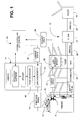
- FIG. 1 is a schematic diagram of a mailpiece inserter having a printer integrated upstream of the various mailpiece handling/processing modules, i.e., a mechanical page buffer/accumulator, folder, inserter, and sealer.
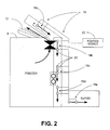
- Figure 2 is an enlarged schematic diagram of a mechanical printed-page buffer which senses the throughput status of mailpiece content material prior to downstream processing by the inserter.
- Fig. 3 is a broken-away side view of a print interface system in accordance with the teachings of the present invention, including a diverter and control mechanism for directing the feed path of duplex-printed content material.
- Fig. 4a is an enlarged view of the diverter in a first position for directing sheet material to an upper staging tray.
- Fig. 4b is an enlarged view of the diverter in a second position for directing sheet material to the page buffer of the mailpiece inserter.
- inventive print interface system and control algorithms therefor are described in the context of a mailpiece inserter system, though the inventive interface system may be used in combination with any sheet handling device which requires printing "on-demand” or "on request".
- inventive interface system is described in the context of a DI 900 Model Mailpiece Inserter, i.e., a mailpiece creation system produced by Pitney Bowes Inc., located in Stamford, State of Connecticut, USA, though, the inventive subject matter may be employed in any mailpiece inserter and/or with any print manager software used in the printing/creation of mail pieces such as PBFirst ®.
- PBFirst is a registered trademark of Pitney Bowes Inc. and is a software product for printing/producing mailpieces processed by a mailpiece inserter system.
- the printers described herein include the HP 4350 BW and HP 4700 Color printers manufactured by Hewlett Packard Company, located in Palo Alto, State of California, U.S.A.
- a dedicated printer 8 is integrated with the mailpiece inserter 10 and is disposed upstream of various inserter devices (also referred to as downstream devices relative to the printer 8) which handle and process the mailpiece content material 12.
- inserter devices also referred to as downstream devices relative to the printer 8
- the terms "mailpiece content material”, “printed material”, “sheets” and /or "sheet material” will used interchangeably.
- an HP 4350 and HP 4700 model printer manufactured by Hewlett Packard (HP), is integrated with the mailpiece inserter 10.
- the HP 4350 printer system is a black & white printer having an output rate of approximately fifty-five (55) pages per minute.
- the HP 4700 is a color printer having an output rate of approximately thirty (30) pages per minute.
- a mechanical buffer or page buffer 16 is disposed downstream of the printer 8 and, inter alia, functions to monitor/track the throughput of printed pages 12 being processed by the inserter 10. More specifically, the page buffer 16 receives printed pages 12 from the printer 8 and includes a plurality of sequential page stations 18a, 18b, 18c, 18d, 18e disposed along a serial feed path. Position sensing devices 20 are located at or along each of the page stations 18a, 18b, 18c, 18d, 18e and monitor the rate that printed pages enter or leave the page buffer 16.
- the sensing devices 20 are operative to issue position signals 22 to a system controller 24 such that the inserter 10 may determine whether a page or sheet 12 is positioned at a particular one of the page stations 18a, 18b,18c, 18d, 18e.
- the sensing devices 20 are photocells, though any position sensor 20 may be employed.
- the rate of change of the position signals 22 may be used by the controller 24 to determine the throughput that content material is processed.
- the "throughput” or “throughput rate” is the magnitude at which sheet material is processed, whether in terms of a steady number of "sheets per unit time", bundles of sheets (e.g., bundles of five (5) sheets requested every several seconds) or a non-steady flow of sheets.
- any downstream device may be adapted to issue a throughput signal indicative of the rate that content material 12 or mailpieces are processed by the inserter 10.
- downstream devices may additionally, or alternatively, include an accumulator 25, a pre-fold accumulator 26, a folder 27, an envelop inserter 28, and/or a sealer 29.
- the system controller 24 monitors the throughput data and issues command signals 30 indicative of the number of pages 12 to be printed by the integrated printer 8. More specifically, the command signals 30 are indicative of a specific page number to begin printing along with the number of pages 12 to follow. For example, the controller 24 may issue command signals 30 requesting the printer 8 to generate page number thirty (Page # 30) plus five (5) additional pages of data. Before this request is issued to the printer (in the more conventional sense), the controller 24 issues the command through a page-based language monitor 34. In the preferred embodiment, the system controller 24 generally issues a command signal 30 to print between three (3) to seven (7) pages with each request, though several command signals 30 may be generated within a very short period of time.
- the mailpiece inserter 10 further includes a User Interface Module (UIM) 36 interposing the mechanical page buffer 16 and the system controller 24.
- the UIM 36 is responsive to the position signals 22 of the mechanical page buffer 16 for determining when additional pages, sheets or content material 12 can be accepted by the page buffer 16.
- the UIM 36 is operative to issue a request signal 38 to the system controller 24, which request signal 38 is indicative of the number of mailpiece content pages 12 to be printed.
- conversion of the position signals 22 to a command signal 30 may be performed by either the system controller 24 or by the UIM 36, depending upon where the program logic/intelligence is located.
- the controller 24 may have received a message that the print job, i.e., determined at the User PC 14, is complete. Consequently, in this instance, the controller 24 will not forward a command signal 30 to the language monitor 34 for issuance to the printer 8.
- the page-based language monitor 34 receives print stream data from a page-based print processor 40 and is interposed between the system controller 24 and the dedicated printer 8.
- the LM 34 is the gate-keeper of data communicated to the printer 8 from the controller 24. More specifically, the LM 34 retains material content data, including an object-data dictionary, for each page of material content and triggers the printer 8 to generate a particular page (i.e., page number) along with N number of additional pages. While this request to print is made by the controller 24, the LM 34 contains the active program code which intercepts the print stream data, i.e., the print control language (PCL), from the printer driver to throttle the rate at which content material 12 is generated by the printer 8.
- PCL print control language
- the page-based LM 34 is operative to vary the flow of print stream data to the printer 8 and vary the production rate of mailpiece content material.
- the LM 34 includes a buffer file capable of storing 300 MB (300,000,000 bytes) of data and, accordingly, the buffer file is capable of storing multiple pages of data, including duplex pages.
- a "page" of data includes all data which may be found on a one- or two-sided sheet of paper.
- the language monitor 34 and print processor 40 issue a print command signal 44 to throttle/control the output of the printer in order to be consistent with or match the throughput of the mailpiece inserter 10.
- a print command signal 44 to throttle/control the output of the printer in order to be consistent with or match the throughput of the mailpiece inserter 10.
- additional or more frequent requests for additional printed pages can be made.
- requests can be made for a fewer number of printed pages or at less frequent intervals to prevent an overload condition or too many sheets from being printed over a prescribed period of time.
- printer throughput and/or operation should not be adversely impacted when performing specialized functions such as duplex printing.
- some printers feed duplex-printed pages to an upper output tray rather than to an accessory feed path.
- certain sheet handling equipment such as certain mailpiece inserters
- various control and/or feed path modifications must be performed without impacting throughput or creating new/additional modes of failure.
- high-output printers are costly pieces of capital equipment, it is oftentimes necessary that the printer be used in multiple modes to justify/amortize the original investment. Consequently, the printer may necessarily include a suitable interface to operate both independently and in conjunction with the sheet handling device.
- printers such as the HP 4350 BW printer, feed duplex-printed pages to an output tray rather than to an accessory feed path. That is, these printers are preprogrammed by the OEM to feed duplex-printed pages to an upper output tray.
- an inventive print interface system 50 is shown including various structural/control modifications to address the challenges associated with duplex printing. More specifically, the print interface system 50 is disposed between a printer 52 and a mailpiece inserter 10.
- the printer 52 includes multiple feed paths FFP, SFP for feeding sheet material 12 to an upper output/staging tray 54 or to a page buffer 16 similar to that described in the preceding paragraphs.
- a first feed path FFP manipulates sheet material 12 internally of the printer 52 such that, following a first operation (denoted by dashed lines in Fig. 3 ), the sheets 12 are passed or staged to the upper staging tray 54.
- the first operation involves passing the sheet material 12 past a print head 55 for printing on a first face surface of the sheet material 12.
- the sheet material 12 reverses direction and re-enters the printer 52 such that a second face of the sheet 12 may pass the print head 55 for printing on the reverse face of the sheet material 12 (i.e., an operation denoted by the dotted line in the Fig. 3 ),
- a second face of the sheet 12 may pass the print head 55 for printing on the reverse face of the sheet material 12 (i.e., an operation denoted by the dotted line in the Fig. 3 )
- Even during the first print operation other pages 12 are being handled/conveyed within the printer 52 such that several pages may pass the print head 55 to print on one face or an opposite face of the sheet 12. That is, to maximize throughput in the duplex printing mode, several sheets 12 may simultaneously be conveyed or handled internally of the printer 52.
- two or more sheets may be printed on one face sheet before one of these same sheets is printed on its opposite face.
- the print interface system 50 includes a controllable/positionable diverter 56 having at least two positions.
- a first position shown in Fig. 4a sheets of material 12 are fed to the upper staging tray 54 in much the same manner as previously performed to reverse the direction of the sheets 12. That is, after printing on one face, the diverter 56 sends sheets 12, i.e., sheets which have now been printed on a single side, along the first feed path FFP to the upper staging tray 54. Following a second print operation associated with printing on the opposite face, the diverter 56 sends the sheets 12, i.e., sheets which have now been printed on both sides, along the second feed path SFP to the page buffer 16.
- a first sheet sensor 60 is disposed proximal to a first printer opening 63, which outputs sheets 12 to the staging tray 54, and a second sheet sensor 60 is disposed immediately upstream of the diverter 56. More specifically, the first sheet sensor 60 optically detects the passage of the leading edge of a sheet 12 as it momentarily enters the staging tray 54 and subsequently reverses direction to re-enter the printer 52. The second sheet sensor 62 optically detects the passage of the trailing edge of a sheet 12 as it passes the diverter 56 into the page buffer 16 of the mailpiece inserter 10.
- sheets of material 12 are printed on one side and are diverted to the upper staging tray 54.
- the diverter 56 is spring-biased in a first direction, or to a position causing the sheets to follow the first feed path FFP, through the first printer opening 63 and past the first sensor 60.
- a staging signal 60S is issued to a controller 66 and an internal timer or clock 68 therein is set/started.
- many staging signals 64 may be issued, thereby setting several timers 68 within the controller 66.
- the second print operation i.e., the operation which prints on the opposing face of the duplex-printed sheet, consumes a fixed period of time X (in seconds)
- X in seconds
- the controller 66 is responsive to the staging signal 60S issued by the first sensor to reposition the diverter 56 from a first position to a second position for directing sheets to the mailpiece inserter 10. Specifically, however, the controller 66 is operative to reposition the diverter 56 following a threshold period of time X from receipt of the staging signal.
- the threshold period X is between 3.0 to 4.0 seconds, and, more precisely, between about 3.3 to about 3.7 seconds.
- the second sensor 62 issues a position signal 62P to the controller 66. That is, when the trailing edge of a sheet 12 passes the optical beam 62B of the second sensor 62, the controller 66 is responsive to the position signal 62P to rapidly reposition the diverter 56 from the second position to its original or first position. Accordingly, the first and second sensors 60, 62 communicate with the controller 66 to ensure that a duplex-printed page 12 is ready to be diverted to the page buffer 16 and has safely past the mechanism of the diverter 56.
- the print interface system 50 includes a mechanism 70 for actuating the diverter 56. Furthermore, the mechanism 70 is adapted to permit separation and/or disengagement of the printer 12 relative to the page buffer 16 of the mailpiece inserter 10.
- the mechanism 70 includes a linear actuator 72, a bell crank 74, a lever arm 76 and a plunger 78. More specifically, the linear actuator 72 and bell crank 74 are mounted to a housing structure 16H (see Fig. 3 ) of the page buffer 16 while the lever arm 76 and plunger 78 are affixed to a bridge structure 52H ( Fig. 3 ), i.e., a structure bridging the output openings (i.e., staging and accessory output areas) of the printer 52.
- the mechanism 70 is adapted to overcome the spring bias force, thereby repositioning the diverter 56 to its second position, i.e., for directing sheet material 12 to the page buffer 16 of the mailpiece inserter 10.
- the actuator 72 retracts linearly to pivot the bell crank 74 in a counterclockwise direction about a pivot point 74P.
- a displacement device 74D e.g., a cylindrical pin, follows an arcuate path to engage a cam surface 76CS at a first end 76 E1 of the lever arm 76.
- the downward displacement of the lever arm 76 is transferred to the plunger 78 by means of a slotted yoke/pin coupling 80 formed at the juncture of the second end 76 E2 of the lever arm 76 and the upper end of the plunger 78. Additionally, the downward motion of the plunger 78 is, in turn, transferred to an actuation pin 82 which engages the diverter 56. Finally, the actuation pin 82 engages a surface of the diverter 56 to effect a force couple or moment M about the pivot mount 56P of the diverter 56. The moment force M, therefore, alternately repositions the diverter 56 between its actuating or sheet diverting positions.
- the bell crank 74 and lever arms 76 are not positively coupled (i.e., the coupling-free interface defined by the interaction of a pin 74D and a cam surface 76 cs ), these elements may be freely separated by the horizontal displacement of the printer 52 relative to the page buffer 16. That is, by separating the printer 52 and page buffer 16 horizontally, in the direction of arrows HL, HR, the print interface system 10 facilitates removal, replacement or repair of the printer 52 and/or printer components which may be accessible only by separating the components.
Landscapes
- Engineering & Computer Science (AREA)
- Mechanical Engineering (AREA)
- Collation Of Sheets And Webs (AREA)
Abstract
Description
- This application claims the benefit of
U.S. andProvisional Patent Applications 60/89959460/899558 which were filed on February 5, 2007 - The present invention relates to systems for integrating a printer with accessory equipment, and, more particularly, to a system for integrating a printer with a sheet handling device, such as a mailpiece inserter and, still more particularly, a system and method for developing an integrated print interface to perform special print operations, such as duplex or dual-sided printing.
- A mail insertion system or a "mailpiece inserter" is commonly employed for producing mailpieces intended for mass mail communications. Such mailpiece inserters are typically used by organizations such as banks, insurance companies and utility companies for producing a large volume of specific mail communications where the contents of each mailpiece are directed to a particular addressee. Also, other organizations, such as direct mailers, use mailpiece inserters for producing mass mailings where the contents of each mailpiece are substantially identical with respect to each addressee.
- In many respects, a typical inserter system resembles a manufacturing assembly line. Sheets and other raw materials (i.e., a web of paper stock, enclosures, and envelopes) enter the inserter system as inputs. Various modules or workstations in the inserter system work cooperatively to process the sheets until a finished mail piece is produced. Typically, inserter systems prepare mail pieces by arranging preprinted sheets of material into a collation, i.e., the content material of the mail piece, on a transport deck. The collation of preprinted sheets may continue to a chassis module where additional sheets or inserts may be added based upon predefined criteria, e.g., an insert being sent to addressees in a particular geographic region. Subsequently, the collation may be folded and placed into envelopes. Once filled, the envelopes are closed, sealed, weighed, and sorted. A postage meter may then be used to apply postage indicia based upon the weight and/or size of the mail piece.
- These inserters typically require the use of "preprinted" sheets which are presented to the various downstream devices by a feed module for subsequent processing. That is, a mailpiece job run is printed to produce an "ordered" stack of mailpiece content material which may be fed to the mailpiece inserter. Scan codes disposed in the margin of the first or last sheet of each mailpiece document provide the instructions necessary to process the mailpiece, i.e., whether additional inserts will be added, how the content material is to be folded (C-fold, Z-fold, etc.) and/or what size envelop will the content material be contained. To facilitate communication of these instructions, a user computer and a printing device are typically network-connected to the mailpiece inserter such that scan codes can be easily printed and interpreted.
- More recently, printers have been integrated with mailpiece inserters so that mailpiece content material may be supplied "on-demand", and/or "just-in-time". Examples of inserters having integrated printers include the DI 900 and DI 950 mailpiece inserters manufactured by Pitney Bowes Inc., located in Stamford, Connecticut, U.S.A. While such integration facilitates the flow and handling of mailpiece content material, it is often desirable, if not essential, that the printers used in such mailpiece inserters be repairable, replaceable or interchangeable with other printers. For example, while the DI 900 and DI 950 inserters employ HP 4350 B&W and HP 4700 color printers, it may, over the course of many years of service, be desirable to substitute these printers with updated versions of the same or to replace these printers with those of other Original Equipment Manufactures (OEMs).
- Inasmuch as the internal program code employed to control such printers is often proprietary/confidential to the OEM, or time consuming to modify, it has become increasingly important to develop an electro-mechanical interface between the printer and inserter which allows the printer to operate independently, while at the same time, operate harmoniously with the mailpiece inserter. That is, the printer must be operative to perform its various functions, including those required by the inserter, without modifying the internal program code of the base printer.
- Examples of such program functions include the requirement to duplex print (dual-sided printing) and conventional printing to an upper stacking tray. With respect to the former, duplex printing produces unique requirements inasmuch as a diverter mechanism, typically used in conjunction with printer accessories (such as a stapler or collator), must be controlled to divert sheet material to the mailpiece inserter. That is, while the diverter is typically controlled by the internal printer program code, i.e., when an accessory is added, the diverter must now be controlled in accordance with a different set of algorithms to cooperate with the inserter. With respect to the latter, the printer must be controlled to send sheet material to a stacking tray when being operated as a conventional printing apparatus and to a downstream module of the inserter (typically referred to as the buffer/accumulator or input module) when being used to generate mailpieces.
- A need, therefore, exists for a print interface system for a sheet handling system to facilitate various operating modes, including conventional printing, duplex printing, and mailpiece creation modes.
- A print interface system is disclosed, including a printer integrated in combination with a sheet handling system such as a mail piece inserter. The print interface system facilitates the handling of sheet material in various operating modes, including conventional printing, duplex printing, and mailpiece creation modes. The system includes a printer having multiple feed paths for printing on opposing face surfaces of a sheet material. One of the feed paths directs sheet material to a staging tray and another feed path directs sheet material to a downstream module of the sheet handling system. The system further includes a positionable diverter for directing sheet material to one of the feed paths and a sheet sensor for determining when a sheet of material has been directed along the feed path leading to the output tray. A controller is operative to alternately repositioning the diverter from one of two positions. A first position directs sheet material to the staging tray following a first print operation, and a second position directs sheet material to the downstream module of the sheet handling system. The controller, furthermore, repositions the diverter following a threshold period of time X from receipt of the staging signal issued by the sheet sensor.
- The accompanying drawings illustrate a presently preferred embodiment of the invention, and together with the general description given above and the detailed description given below, serve to explain the principles of the invention. As shown throughout the drawings, like reference numerals designate like or corresponding parts.
Figure 1 is a schematic diagram of a mailpiece inserter having a printer integrated upstream of the various mailpiece handling/processing modules, i.e., a mechanical page buffer/accumulator, folder, inserter, and sealer. -
Figure 2 is an enlarged schematic diagram of a mechanical printed-page buffer which senses the throughput status of mailpiece content material prior to downstream processing by the inserter. -
Fig. 3 is a broken-away side view of a print interface system in accordance with the teachings of the present invention, including a diverter and control mechanism for directing the feed path of duplex-printed content material. -
Fig. 4a is an enlarged view of the diverter in a first position for directing sheet material to an upper staging tray. -
Fig. 4b is an enlarged view of the diverter in a second position for directing sheet material to the page buffer of the mailpiece inserter. - The inventive print interface system and control algorithms therefor are described in the context of a mailpiece inserter system, though the inventive interface system may be used in combination with any sheet handling device which requires printing "on-demand" or "on request". Further, the invention is described in the context of a DI 900 Model Mailpiece Inserter, i.e., a mailpiece creation system produced by Pitney Bowes Inc., located in Stamford, State of Connecticut, USA, though, the inventive subject matter may be employed in any mailpiece inserter and/or with any print manager software used in the printing/creation of mail pieces such as PBFirst ®. PBFirst is a registered trademark of Pitney Bowes Inc. and is a software product for printing/producing mailpieces processed by a mailpiece inserter system. Moreover, while the print interface system and control algorithms thereof are intended for use in combination with printers of various makes and models, the printers described herein include the HP 4350 BW and HP 4700 Color printers manufactured by Hewlett Packard Company, located in Palo Alto, State of California, U.S.A.
- Before discussing the invention in greater detail, it will be useful to understand the basic system architecture and operation of the mailpiece inserter, including the cooperation of various system components and elements. In
Figure 1 , adedicated printer 8 is integrated with themailpiece inserter 10 and is disposed upstream of various inserter devices (also referred to as downstream devices relative to the printer 8) which handle and process themailpiece content material 12. Throughout the description, the terms "mailpiece content material", "printed material", "sheets" and /or "sheet material" will used interchangeably. In the described embodiment, an HP 4350 and HP 4700 model printer, manufactured by Hewlett Packard (HP), is integrated with themailpiece inserter 10. The HP 4350 printer system is a black & white printer having an output rate of approximately fifty-five (55) pages per minute. The HP 4700 is a color printer having an output rate of approximately thirty (30) pages per minute. - In
Figs. 1 and2 , a mechanical buffer orpage buffer 16 is disposed downstream of theprinter 8 and, inter alia, functions to monitor/track the throughput of printedpages 12 being processed by theinserter 10. More specifically, thepage buffer 16 receives printedpages 12 from theprinter 8 and includes a plurality ofsequential page stations Position sensing devices 20 are located at or along each of thepage stations page buffer 16. Furthermore, thesensing devices 20 are operative to issueposition signals 22 to asystem controller 24 such that theinserter 10 may determine whether a page orsheet 12 is positioned at a particular one of thepage stations sensing devices 20 are photocells, though anyposition sensor 20 may be employed. - The rate of change of the position signals 22 (i.e., the signals issued by the page buffer 16) may be used by the
controller 24 to determine the throughput that content material is processed. Fundamentally, the "throughput" or "throughput rate" is the magnitude at which sheet material is processed, whether in terms of a steady number of "sheets per unit time", bundles of sheets (e.g., bundles of five (5) sheets requested every several seconds) or a non-steady flow of sheets. Generally, it is the objective of thesystem controller 24 to drive theprinter 8 to generatecontent material 12 at a rate consistent, or commensurate, with the rate of processing by other downstream devices of themailpiece creation system 10. While in the described embodiment the initial/first downstream device is apage buffer 16, it should be appreciated that any downstream device may be adapted to issue a throughput signal indicative of the rate thatcontent material 12 or mailpieces are processed by theinserter 10. InFigure 1 , such downstream devices may additionally, or alternatively, include anaccumulator 25, apre-fold accumulator 26, afolder 27, anenvelop inserter 28, and/or asealer 29. - The
system controller 24 monitors the throughput data and issues command signals 30 indicative of the number ofpages 12 to be printed by theintegrated printer 8. More specifically, the command signals 30 are indicative of a specific page number to begin printing along with the number ofpages 12 to follow. For example, thecontroller 24 may issue command signals 30 requesting theprinter 8 to generate page number thirty (Page # 30) plus five (5) additional pages of data. Before this request is issued to the printer (in the more conventional sense), thecontroller 24 issues the command through a page-based language monitor 34. In the preferred embodiment, thesystem controller 24 generally issues acommand signal 30 to print between three (3) to seven (7) pages with each request, thoughseveral command signals 30 may be generated within a very short period of time. - The
mailpiece inserter 10 further includes a User Interface Module (UIM) 36 interposing themechanical page buffer 16 and thesystem controller 24. TheUIM 36 is responsive to the position signals 22 of themechanical page buffer 16 for determining when additional pages, sheets orcontent material 12 can be accepted by thepage buffer 16. Furthermore, theUIM 36 is operative to issue arequest signal 38 to thesystem controller 24, which requestsignal 38 is indicative of the number ofmailpiece content pages 12 to be printed. Hence, conversion of the position signals 22 to acommand signal 30 may be performed by either thesystem controller 24 or by theUIM 36, depending upon where the program logic/intelligence is located. It should be further appreciated that while a request may be made by theUIM 36, thecontroller 24 may have received a message that the print job, i.e., determined at theUser PC 14, is complete. Consequently, in this instance, thecontroller 24 will not forward acommand signal 30 to the language monitor 34 for issuance to theprinter 8. - The page-based language monitor 34 (hereinafter the "language monitor" or "LM") receives print stream data from a page-based
print processor 40 and is interposed between thesystem controller 24 and thededicated printer 8. In the broadest sense, theLM 34 is the gate-keeper of data communicated to theprinter 8 from thecontroller 24. More specifically, theLM 34 retains material content data, including an object-data dictionary, for each page of material content and triggers theprinter 8 to generate a particular page (i.e., page number) along with N number of additional pages. While this request to print is made by thecontroller 24, theLM 34 contains the active program code which intercepts the print stream data, i.e., the print control language (PCL), from the printer driver to throttle the rate at whichcontent material 12 is generated by theprinter 8. - More specifically, the page-based
LM 34 is operative to vary the flow of print stream data to theprinter 8 and vary the production rate of mailpiece content material. Additionally, theLM 34 includes a buffer file capable of storing 300 MB (300,000,000 bytes) of data and, accordingly, the buffer file is capable of storing multiple pages of data, including duplex pages. Hence, in the context used herein, a "page" of data includes all data which may be found on a one- or two-sided sheet of paper. - In operation, the
language monitor 34 andprint processor 40 issue a print command signal 44 to throttle/control the output of the printer in order to be consistent with or match the throughput of themailpiece inserter 10. As more pages are processed by theinserter 10, additional or more frequent requests for additional printed pages can be made. Should theinserter 10 require additional processing time to collate and/or combine a complex variety of inserts, requests can be made for a fewer number of printed pages or at less frequent intervals to prevent an overload condition or too many sheets from being printed over a prescribed period of time. - When integrating a printer with a sheet handling device such as a mailpiece creation system/inserter, several requirements and objectives should be met/obtained. First, to ensure maximum throughput, the system should minimize time gaps between a request for printing and the generation of printed content material. Secondly, to the extent that various application software may be employed to generate print jobs, it is desirable to affect integration of the printer without modifying its underlying print program code. As mentioned in the Background of the Invention, aside from the cost associated with program code modification, such program code is oftentimes proprietary to the original equipment manufacturer (OEM). Consequently, it may be difficult to obtain access to or overwrite the original program code.
- Additionally, the printer throughput and/or operation should not be adversely impacted when performing specialized functions such as duplex printing. As will be discussed hereinafter, some printers feed duplex-printed pages to an upper output tray rather than to an accessory feed path. Inasmuch as certain sheet handling equipment, such as certain mailpiece inserters, receive printed pages from an accessory feed path, various control and/or feed path modifications must be performed without impacting throughput or creating new/additional modes of failure. Finally, inasmuch such high-output printers are costly pieces of capital equipment, it is oftentimes necessary that the printer be used in multiple modes to justify/amortize the original investment. Consequently, the printer may necessarily include a suitable interface to operate both independently and in conjunction with the sheet handling device. These requirements/objectives are discussed and met in the subsequent description.
- To accommodate duplex printing, certain printers, such as the HP 4350 BW printer, feed duplex-printed pages to an output tray rather than to an accessory feed path. That is, these printers are preprogrammed by the OEM to feed duplex-printed pages to an upper output tray. In
Fig. 3 , an inventiveprint interface system 50 is shown including various structural/control modifications to address the challenges associated with duplex printing. More specifically, theprint interface system 50 is disposed between aprinter 52 and amailpiece inserter 10. Theprinter 52 includes multiple feed paths FFP, SFP for feedingsheet material 12 to an upper output/staging tray 54 or to apage buffer 16 similar to that described in the preceding paragraphs. A first feed path FFP manipulatessheet material 12 internally of theprinter 52 such that, following a first operation (denoted by dashed lines inFig. 3 ), thesheets 12 are passed or staged to theupper staging tray 54. The first operation involves passing thesheet material 12 past aprint head 55 for printing on a first face surface of thesheet material 12. - Following a brief period (typically a fraction of a second) in the staging
tray 54, thesheet material 12 reverses direction and re-enters theprinter 52 such that a second face of thesheet 12 may pass theprint head 55 for printing on the reverse face of the sheet material 12 (i.e., an operation denoted by the dotted line in theFig. 3 ), Even during the first print operation,other pages 12 are being handled/conveyed within theprinter 52 such that several pages may pass theprint head 55 to print on one face or an opposite face of thesheet 12. That is, to maximize throughput in the duplex printing mode,several sheets 12 may simultaneously be conveyed or handled internally of theprinter 52. Furthermore, depending upon the sequence of print operations, two or more sheets may be printed on one face sheet before one of these same sheets is printed on its opposite face. - In view of the various print operations being performed while printing in the duplex mode, several difficulties must be understood and challenges overcome to ensure proper handling of the printed
content material 12 at theprint interface 50. For example, when theprint interface system 50 is operative to feedsheets 12 to themailpiece inserter 10, a second feed path SFP is established to forward printed content material to thepage buffer 16. As a result, a controller or control algorithm must be employed to divert duplex pages to thepage buffer 16 rather than to theupper tray 54. It will be recalled that the normal or preprogrammed print operation of theprinter 52 calls for duplex-printed pages to be fed to the upper output tray. - Inasmuch as such duplex printed
sheets 12 must be diverted to themailpiece inserter 10 when producing mailpieces, theprint interface system 50 includes a controllable/positionable diverter 56 having at least two positions. In a first position shown inFig. 4a , sheets ofmaterial 12 are fed to theupper staging tray 54 in much the same manner as previously performed to reverse the direction of thesheets 12. That is, after printing on one face, thediverter 56 sendssheets 12, i.e., sheets which have now been printed on a single side, along the first feed path FFP to theupper staging tray 54. Following a second print operation associated with printing on the opposite face, thediverter 56 sends thesheets 12, i.e., sheets which have now been printed on both sides, along the second feed path SFP to thepage buffer 16. - To acquire data/information concerning when a
sheet 12 has passed various locations along the feed paths FFP, SFP,sheet sensors sheet 12. Afirst sheet sensor 60 is disposed proximal to afirst printer opening 63, which outputssheets 12 to the stagingtray 54, and asecond sheet sensor 60 is disposed immediately upstream of thediverter 56. More specifically, thefirst sheet sensor 60 optically detects the passage of the leading edge of asheet 12 as it momentarily enters the stagingtray 54 and subsequently reverses direction to re-enter theprinter 52. Thesecond sheet sensor 62 optically detects the passage of the trailing edge of asheet 12 as it passes thediverter 56 into thepage buffer 16 of themailpiece inserter 10. - In operation, sheets of
material 12 are printed on one side and are diverted to theupper staging tray 54. At this moment, thediverter 56 is spring-biased in a first direction, or to a position causing the sheets to follow the first feed path FFP, through thefirst printer opening 63 and past thefirst sensor 60. When the leading edge of each of the stagedsheets 12 passes theoptical beam 60B of thesensor 60, astaging signal 60S is issued to acontroller 66 and an internal timer orclock 68 therein is set/started. Inasmuch as a plurality ofsheets 12 may be staged into thetray 54 over the course of several seconds, many staging signals 64 may be issued, thereby settingseveral timers 68 within thecontroller 66. Inasmuch as the second print operation, i.e., the operation which prints on the opposing face of the duplex-printed sheet, consumes a fixed period of time X (in seconds), it can be concluded that any identifiedsheet 12 which was first detected X seconds prior, i.e., by thefirst sensor 60, has now been printed on both face surfaces. Accordingly, the identifiedsheet 12 is ready to be passed to thepage buffer 16 of themailpiece inserter 10. - In
Figs. 4a and 4b , thecontroller 66 is responsive to thestaging signal 60S issued by the first sensor to reposition thediverter 56 from a first position to a second position for directing sheets to themailpiece inserter 10. Specifically, however, thecontroller 66 is operative to reposition thediverter 56 following a threshold period of time X from receipt of the staging signal. In the described embodiment, the threshold period X is between 3.0 to 4.0 seconds, and, more precisely, between about 3.3 to about 3.7 seconds. - To ensure that the
diverter 56 remains in its second position for a period of time sufficient to permit passage of a duplex-printedsheet 12, thesecond sensor 62 issues aposition signal 62P to thecontroller 66. That is, when the trailing edge of asheet 12 passes theoptical beam 62B of thesecond sensor 62, thecontroller 66 is responsive to theposition signal 62P to rapidly reposition thediverter 56 from the second position to its original or first position. Accordingly, the first andsecond sensors controller 66 to ensure that a duplex-printedpage 12 is ready to be diverted to thepage buffer 16 and has safely past the mechanism of thediverter 56. - Referring to
Figs. 3 and4b , theprint interface system 50 includes amechanism 70 for actuating thediverter 56. Furthermore, themechanism 70 is adapted to permit separation and/or disengagement of theprinter 12 relative to thepage buffer 16 of themailpiece inserter 10. In the described embodiment, themechanism 70 includes alinear actuator 72, abell crank 74, alever arm 76 and aplunger 78. More specifically, thelinear actuator 72 and bell crank 74 are mounted to ahousing structure 16H (seeFig. 3 ) of thepage buffer 16 while thelever arm 76 andplunger 78 are affixed to abridge structure 52H (Fig. 3 ), i.e., a structure bridging the output openings (i.e., staging and accessory output areas) of theprinter 52. - Inasmuch as the
diverter 56 is rotationally spring-biased to a first position, themechanism 70 is adapted to overcome the spring bias force, thereby repositioning thediverter 56 to its second position, i.e., for directingsheet material 12 to thepage buffer 16 of themailpiece inserter 10. Upon receiving a command signal from thecontroller 66, theactuator 72 retracts linearly to pivot the bell crank 74 in a counterclockwise direction about apivot point 74P. As the bell crank 74 pivots, adisplacement device 74D, e.g., a cylindrical pin, follows an arcuate path to engage a cam surface 76CS at afirst end 76E1 of thelever arm 76. Inasmuch as thelever arm 76 is pivot mounted to thebridge structure 74 about a central fulcrum 76CF, the upward vertical motion of thepin 74P effects a downward vertical displacement of thelever arm 76 at its opposingsecond end 76E2. - The downward displacement of the
lever arm 76 is transferred to theplunger 78 by means of a slotted yoke/pin coupling 80 formed at the juncture of thesecond end 76E2 of thelever arm 76 and the upper end of theplunger 78. Additionally, the downward motion of theplunger 78 is, in turn, transferred to anactuation pin 82 which engages thediverter 56. Finally, theactuation pin 82 engages a surface of thediverter 56 to effect a force couple or moment M about thepivot mount 56P of thediverter 56. The moment force M, therefore, alternately repositions thediverter 56 between its actuating or sheet diverting positions. - Inasmuch as the bell crank 74 and
lever arms 76 are not positively coupled (i.e., the coupling-free interface defined by the interaction of apin 74D and a cam surface 76cs), these elements may be freely separated by the horizontal displacement of theprinter 52 relative to thepage buffer 16. That is, by separating theprinter 52 andpage buffer 16 horizontally, in the direction of arrows HL, HR, theprint interface system 10 facilitates removal, replacement or repair of theprinter 52 and/or printer components which may be accessible only by separating the components. - It is to be understood that the present invention is not to be considered as limited to the specific embodiments described above and shown in the accompanying drawings. The illustrations merely show the best mode presently contemplated for carrying out the invention, and which is susceptible to such changes as may be obvious to one skilled in the art. The invention is intended to cover all such variations, modifications and equivalents thereof as may be deemed to be within the scope of the claims appended hereto.
Claims (11)
- A print interface system (50) for a sheet handling system, comprising:a printer (52) having multiple feed paths (FFP,SFP) for printing on opposing surfaces of a sheet material (12), a first feed path (FFP) directing sheet material (12) to a staging tray (54) and a second feed path (SFP) directing sheet material (12) to a downstream module (10) of the sheet handling system;a positionable diverter (56) for directing sheet material (12) to one of the first and second feed paths (FFP,SFP),a sheet sensor (60) for determining when a sheet of material (12) has been directed along the first feed path (FFP) and issuing a staging signal (605) indicative thereof; anda controller (66), responsive to the staging signal (605), for alternately repositioning the diverter (56) from one of two positions, a first position for directing sheet material (12) to the first feed path (FFP), and a second position for directing sheet material (12) to the second feed path (SFP), the controller (66), furthermore, operative to reposition the diverter (56) from the first to the second position following a threshold period of time from receipt of the staging signal (605).
- The print interface system (50) according to Claim 1 further comprising a timer (68), and wherein the sheet sensor (60) starts the timer (68) upon sensing a leading edge of the sheet material (12) and wherein the controller (66) determines the threshold period of time based upon input from the timer (68).
- The print interface system (50) according to Claim 1 or 2 further comprising multiple timers (68), each timer associated with individual sheets of the sheet material (12) which are conveyed internally of the printer (52).
- The print interface system (50) according to any precedingclaim wherein the threshold period of time is between about 3.0 to about 4.0 seconds.
- The print interface system (50) according to any of Claims 1 to 3 wherein the threshold period of time is between about 3.3 to about 3.7 seconds.
- The print interface system (50) according to any preceding claim wherein the second feed (SFP) defines a downstream position beyond the diverter (56) and further comprises:a sensor (62) for determining when the sheet of material (12) has passed the downstream position and issuing a position signal (62P) indicative thereof; andwherein the controller (66) is responsive to the position signal (62P) to prevent repositioning of the diverter (56) to the first position until the sheet of material (12) has passed the downstream position.
- The print interface system (50) according to any preceding claim wherein the staging tray (54) is dually operative to stage sheet material (12) for printing on opposing surfaces thereof and as an output tray (54) for stacking sheet material (12).
- The print interface system (50) according to any preceding claim wherein the downstream module is a page buffer (16) of a mailpiece inserter (10).
- The print interface system (50) according to any preceding claim wherein the sheet sensor (60) optically senses a leading edge of the sheet material (12) as each sheet of sheet material (12) exits the printer (52) from an output opening (63) to the staging tray (54).
- The print interface system (50) according to any preceding claim further comprising a mechanism (70) for actuating the diverter (56) and defining a coupling-free interface adapted to permit separation of the printer (52) relative to the sheet handling system.
- The print interface system (50) according to any preceding claim wherein the mechanism (70) includes an actuator (72) associated with the downstream module of the sheet handling device, a pivotable actuation lever (76) disposed proximal to the diverter (56), the actuation lever having a cam surface (76CS) at one end thereof and connecting to the diverter (56) at the other end, and a displacement pin (74D) connecting to the actuator (72) at one end and engaging the cam surface at the other end, wherein the cam surface (76CS) and displacement pin (74D) define a separable interface to facilitate separation of the printer (52) relative to the sheet handling system.
Applications Claiming Priority (2)
| Application Number | Priority Date | Filing Date | Title |
|---|---|---|---|
| US89959407P | 2007-02-05 | 2007-02-05 | |
| US11/731,373 US7887053B2 (en) | 2007-02-05 | 2007-03-30 | Print interface system for a sheet handling device |
Publications (3)
| Publication Number | Publication Date |
|---|---|
| EP1952995A2 true EP1952995A2 (en) | 2008-08-06 |
| EP1952995A3 EP1952995A3 (en) | 2012-12-26 |
| EP1952995B1 EP1952995B1 (en) | 2014-07-16 |
Family
ID=39272058
Family Applications (1)
| Application Number | Title | Priority Date | Filing Date |
|---|---|---|---|
| EP08001904.5A Ceased EP1952995B1 (en) | 2007-02-05 | 2008-02-01 | Print interface system for a sheet handling device |
Country Status (1)
| Country | Link |
|---|---|
| EP (1) | EP1952995B1 (en) |
Cited By (1)
| Publication number | Priority date | Publication date | Assignee | Title |
|---|---|---|---|---|
| US9134928B2 (en) | 2011-01-28 | 2015-09-15 | Ricoh Production Print Solutions LLC | Print job processing in an automated document factory environment |
Family Cites Families (5)
| Publication number | Priority date | Publication date | Assignee | Title |
|---|---|---|---|---|
| JP2825846B2 (en) * | 1988-08-18 | 1998-11-18 | 株式会社リコー | Sheet transport device in double-sided image recording device |
| JP3110432B2 (en) * | 1989-08-07 | 2000-11-20 | 株式会社リコー | Double-sided device |
| JPH04112061A (en) * | 1990-08-31 | 1992-04-14 | Nec Corp | Printer |
| US5813326A (en) * | 1994-12-22 | 1998-09-29 | Pitney Bowes Inc. | Mailing machine utilizing ink jet printer |
| JP4598591B2 (en) * | 2005-04-28 | 2010-12-15 | 京セラミタ株式会社 | Paper transport branch device |
-
2008
- 2008-02-01 EP EP08001904.5A patent/EP1952995B1/en not_active Ceased
Non-Patent Citations (1)
| Title |
|---|
| None |
Cited By (1)
| Publication number | Priority date | Publication date | Assignee | Title |
|---|---|---|---|---|
| US9134928B2 (en) | 2011-01-28 | 2015-09-15 | Ricoh Production Print Solutions LLC | Print job processing in an automated document factory environment |
Also Published As
| Publication number | Publication date |
|---|---|
| EP1952995A3 (en) | 2012-12-26 |
| EP1952995B1 (en) | 2014-07-16 |
Similar Documents
| Publication | Publication Date | Title |
|---|---|---|
| US5754434A (en) | Continuous forms integrated system | |
| KR100255580B1 (en) | Mailing System Controlled by the Computer Software | |
| CA2164674C (en) | Apparatus and method for preparing a mail piece | |
| JP2815705B2 (en) | Selective flexographic printing | |
| US8040539B2 (en) | Method and system for mitigating errors when processing print stream data | |
| US7887053B2 (en) | Print interface system for a sheet handling device | |
| CA2174046C (en) | Method for generating a mailpiece | |
| CN1122751A (en) | Apparatus for printing characters onto both surfaces of a sheet materials | |
| EP1901237B1 (en) | Method and system for high speed digital metering using low velocity print technology | |
| EP1952995B1 (en) | Print interface system for a sheet handling device | |
| US7581894B2 (en) | Method and system for controlling print operations in a mailpiece creation system | |
| US7965404B2 (en) | Method for regenerating mailpiece content material in a mailpiece creation system | |
| US6988842B2 (en) | Method and apparatus for continuous high speed digital metering using multiple print heads | |
| EP1952996B1 (en) | Multi-function low profile print interface for a sheet handling device | |
| US6893175B2 (en) | Method and system for high speed digital metering | |
| EP2030930B1 (en) | Sheet/page buffer for sheet handling apparatus | |
| EP1895474B1 (en) | Apparatus and method for control of print data download | |
| JP5893499B2 (en) | Seal printing system | |
| US12023916B2 (en) | Printing apparatus with cutter and inverting mechanism | |
| US6505902B1 (en) | Mail piece producing machine having a wide swath envelope printing module | |
| EP1521218B1 (en) | Method and system for high speed digital metering | |
| US5257040A (en) | System for printing asymmetrically positioned pairs of envelopes | |
| JPH1035997A (en) | Printing sheet sorting device | |
| US20060024112A1 (en) | High speed parallel printing using meters and intelligent sorting of printed materials | |
| GB2416516A (en) | High speed parallel printing using meters and intelligent sorting of printed materials |
Legal Events
| Date | Code | Title | Description |
|---|---|---|---|
| PUAI | Public reference made under article 153(3) epc to a published international application that has entered the european phase |
Free format text: ORIGINAL CODE: 0009012 |
|
| AK | Designated contracting states |
Kind code of ref document: A2 Designated state(s): AT BE BG CH CY CZ DE DK EE ES FI FR GB GR HR HU IE IS IT LI LT LU LV MC MT NL NO PL PT RO SE SI SK TR |
|
| AX | Request for extension of the european patent |
Extension state: AL BA MK RS |
|
| PUAL | Search report despatched |
Free format text: ORIGINAL CODE: 0009013 |
|
| AK | Designated contracting states |
Kind code of ref document: A3 Designated state(s): AT BE BG CH CY CZ DE DK EE ES FI FR GB GR HR HU IE IS IT LI LT LU LV MC MT NL NO PL PT RO SE SI SK TR |
|
| AX | Request for extension of the european patent |
Extension state: AL BA MK RS |
|
| RIC1 | Information provided on ipc code assigned before grant |
Ipc: B41J 3/60 20060101AFI20121116BHEP Ipc: B41J 11/00 20060101ALI20121116BHEP Ipc: B65H 85/00 20060101ALI20121116BHEP Ipc: B65H 29/58 20060101ALI20121116BHEP Ipc: B41J 13/00 20060101ALI20121116BHEP |
|
| 17P | Request for examination filed |
Effective date: 20130304 |
|
| AKX | Designation fees paid |
Designated state(s): DE FR GB |
|
| GRAP | Despatch of communication of intention to grant a patent |
Free format text: ORIGINAL CODE: EPIDOSNIGR1 |
|
| RIC1 | Information provided on ipc code assigned before grant |
Ipc: B41J 11/00 20060101ALI20131118BHEP Ipc: B65H 85/00 20060101ALI20131118BHEP Ipc: B41J 13/00 20060101ALI20131118BHEP Ipc: B65H 29/58 20060101ALI20131118BHEP Ipc: B41J 3/60 20060101AFI20131118BHEP |
|
| INTG | Intention to grant announced |
Effective date: 20131210 |
|
| GRAP | Despatch of communication of intention to grant a patent |
Free format text: ORIGINAL CODE: EPIDOSNIGR1 |
|
| INTG | Intention to grant announced |
Effective date: 20140224 |
|
| GRAS | Grant fee paid |
Free format text: ORIGINAL CODE: EPIDOSNIGR3 |
|
| GRAA | (expected) grant |
Free format text: ORIGINAL CODE: 0009210 |
|
| AK | Designated contracting states |
Kind code of ref document: B1 Designated state(s): DE FR GB |
|
| REG | Reference to a national code |
Ref country code: GB Ref legal event code: FG4D |
|
| RIN2 | Information on inventor provided after grant (corrected) |
Inventor name: BALDINO, NEIL F. Inventor name: FAIRWEATHER, JAMES A. Inventor name: ALLEN, ROBERT J. Inventor name: LYGA, THOMAS M. Inventor name: SMITH, AARON D. |
|
| REG | Reference to a national code |
Ref country code: DE Ref legal event code: R096 Ref document number: 602008033261 Country of ref document: DE Effective date: 20140828 |
|
| REG | Reference to a national code |
Ref country code: DE Ref legal event code: R097 Ref document number: 602008033261 Country of ref document: DE |
|
| PLBE | No opposition filed within time limit |
Free format text: ORIGINAL CODE: 0009261 |
|
| STAA | Information on the status of an ep patent application or granted ep patent |
Free format text: STATUS: NO OPPOSITION FILED WITHIN TIME LIMIT |
|
| 26N | No opposition filed |
Effective date: 20150417 |
|
| REG | Reference to a national code |
Ref country code: FR Ref legal event code: PLFP Year of fee payment: 9 |
|
| REG | Reference to a national code |
Ref country code: FR Ref legal event code: PLFP Year of fee payment: 10 |
|
| REG | Reference to a national code |
Ref country code: FR Ref legal event code: PLFP Year of fee payment: 11 |
|
| PGFP | Annual fee paid to national office [announced via postgrant information from national office to epo] |
Ref country code: GB Payment date: 20190227 Year of fee payment: 12 Ref country code: DE Payment date: 20190227 Year of fee payment: 12 |
|
| PGFP | Annual fee paid to national office [announced via postgrant information from national office to epo] |
Ref country code: FR Payment date: 20190225 Year of fee payment: 12 |
|
| REG | Reference to a national code |
Ref country code: DE Ref legal event code: R119 Ref document number: 602008033261 Country of ref document: DE |
|
| GBPC | Gb: european patent ceased through non-payment of renewal fee |
Effective date: 20200201 |
|
| PG25 | Lapsed in a contracting state [announced via postgrant information from national office to epo] |
Ref country code: DE Free format text: LAPSE BECAUSE OF NON-PAYMENT OF DUE FEES Effective date: 20200901 Ref country code: GB Free format text: LAPSE BECAUSE OF NON-PAYMENT OF DUE FEES Effective date: 20200201 Ref country code: FR Free format text: LAPSE BECAUSE OF NON-PAYMENT OF DUE FEES Effective date: 20200229 |