EP1521218B1 - Method and system for high speed digital metering - Google Patents
Method and system for high speed digital metering Download PDFInfo
- Publication number
- EP1521218B1 EP1521218B1 EP04023374.4A EP04023374A EP1521218B1 EP 1521218 B1 EP1521218 B1 EP 1521218B1 EP 04023374 A EP04023374 A EP 04023374A EP 1521218 B1 EP1521218 B1 EP 1521218B1
- Authority
- EP
- European Patent Office
- Prior art keywords
- transport
- downstream
- upstream
- velocity
- Prior art date
- Legal status (The legal status is an assumption and is not a legal conclusion. Google has not performed a legal analysis and makes no representation as to the accuracy of the status listed.)
- Expired - Lifetime
Links
- 238000000034 method Methods 0.000 title claims description 26
- 230000032258 transport Effects 0.000 claims description 172
- 238000007639 printing Methods 0.000 claims description 139
- 238000011144 upstream manufacturing Methods 0.000 claims description 100
- 230000033001 locomotion Effects 0.000 claims description 87
- 238000006073 displacement reaction Methods 0.000 claims description 68
- 238000012545 processing Methods 0.000 claims description 22
- 230000001133 acceleration Effects 0.000 claims description 20
- 238000012423 maintenance Methods 0.000 claims description 19
- 230000007723 transport mechanism Effects 0.000 claims description 5
- 238000007641 inkjet printing Methods 0.000 claims description 2
- 230000008878 coupling Effects 0.000 claims 1
- 238000010168 coupling process Methods 0.000 claims 1
- 238000005859 coupling reaction Methods 0.000 claims 1
- 238000005516 engineering process Methods 0.000 description 15
- 238000004519 manufacturing process Methods 0.000 description 6
- 230000008859 change Effects 0.000 description 4
- 238000001514 detection method Methods 0.000 description 4
- 230000007246 mechanism Effects 0.000 description 4
- 230000008569 process Effects 0.000 description 4
- 238000013507 mapping Methods 0.000 description 3
- 238000010926 purge Methods 0.000 description 3
- 238000007789 sealing Methods 0.000 description 3
- 230000008901 benefit Effects 0.000 description 2
- 230000000694 effects Effects 0.000 description 2
- 230000000977 initiatory effect Effects 0.000 description 2
- 238000003780 insertion Methods 0.000 description 2
- 230000037431 insertion Effects 0.000 description 2
- 230000000737 periodic effect Effects 0.000 description 2
- 238000006467 substitution reaction Methods 0.000 description 2
- 230000001960 triggered effect Effects 0.000 description 2
- 230000009471 action Effects 0.000 description 1
- 230000004913 activation Effects 0.000 description 1
- 238000004364 calculation method Methods 0.000 description 1
- 238000010586 diagram Methods 0.000 description 1
- 230000002708 enhancing effect Effects 0.000 description 1
- 238000009434 installation Methods 0.000 description 1
- 230000007774 longterm Effects 0.000 description 1
- 230000007257 malfunction Effects 0.000 description 1
- 239000000463 material Substances 0.000 description 1
- 238000002360 preparation method Methods 0.000 description 1
- 239000002994 raw material Substances 0.000 description 1
- 238000004904 shortening Methods 0.000 description 1
- 238000013519 translation Methods 0.000 description 1
- 238000005303 weighing Methods 0.000 description 1
- 238000009736 wetting Methods 0.000 description 1
Images


Classifications
-
- G—PHYSICS
- G07—CHECKING-DEVICES
- G07B—TICKET-ISSUING APPARATUS; FARE-REGISTERING APPARATUS; FRANKING APPARATUS
- G07B17/00—Franking apparatus
- G07B17/00459—Details relating to mailpieces in a franking system
- G07B17/00508—Printing or attaching on mailpieces
-
- B—PERFORMING OPERATIONS; TRANSPORTING
- B65—CONVEYING; PACKING; STORING; HANDLING THIN OR FILAMENTARY MATERIAL
- B65H—HANDLING THIN OR FILAMENTARY MATERIAL, e.g. SHEETS, WEBS, CABLES
- B65H29/00—Delivering or advancing articles from machines; Advancing articles to or into piles
- B65H29/12—Delivering or advancing articles from machines; Advancing articles to or into piles by means of the nip between two, or between two sets of, moving tapes or bands or rollers
- B65H29/125—Delivering or advancing articles from machines; Advancing articles to or into piles by means of the nip between two, or between two sets of, moving tapes or bands or rollers between two sets of rollers
-
- B—PERFORMING OPERATIONS; TRANSPORTING
- B65—CONVEYING; PACKING; STORING; HANDLING THIN OR FILAMENTARY MATERIAL
- B65H—HANDLING THIN OR FILAMENTARY MATERIAL, e.g. SHEETS, WEBS, CABLES
- B65H5/00—Feeding articles separated from piles; Feeding articles to machines
- B65H5/06—Feeding articles separated from piles; Feeding articles to machines by rollers or balls, e.g. between rollers
- B65H5/062—Feeding articles separated from piles; Feeding articles to machines by rollers or balls, e.g. between rollers between rollers or balls
-
- G—PHYSICS
- G07—CHECKING-DEVICES
- G07B—TICKET-ISSUING APPARATUS; FARE-REGISTERING APPARATUS; FRANKING APPARATUS
- G07B17/00—Franking apparatus
- G07B17/00459—Details relating to mailpieces in a franking system
- G07B17/00467—Transporting mailpieces
-
- G—PHYSICS
- G07—CHECKING-DEVICES
- G07B—TICKET-ISSUING APPARATUS; FARE-REGISTERING APPARATUS; FRANKING APPARATUS
- G07B17/00—Franking apparatus
- G07B17/00185—Details internally of apparatus in a franking system, e.g. franking machine at customer or apparatus at post office
- G07B17/00314—Communication within apparatus, personal computer [PC] system, or server, e.g. between printhead and central unit in a franking machine
- G07B2017/00322—Communication between components/modules/parts, e.g. printer, printhead, keyboard, conveyor or central unit
-
- G—PHYSICS
- G07—CHECKING-DEVICES
- G07B—TICKET-ISSUING APPARATUS; FARE-REGISTERING APPARATUS; FRANKING APPARATUS
- G07B17/00—Franking apparatus
- G07B17/00459—Details relating to mailpieces in a franking system
- G07B17/00508—Printing or attaching on mailpieces
- G07B2017/00516—Details of printing apparatus
- G07B2017/00524—Printheads
- G07B2017/00532—Inkjet
-
- G—PHYSICS
- G07—CHECKING-DEVICES
- G07B—TICKET-ISSUING APPARATUS; FARE-REGISTERING APPARATUS; FRANKING APPARATUS
- G07B17/00—Franking apparatus
- G07B17/00459—Details relating to mailpieces in a franking system
- G07B17/00508—Printing or attaching on mailpieces
- G07B2017/00516—Details of printing apparatus
- G07B2017/00556—Ensuring quality of print
- G07B2017/00564—Ensuring correct position of print on mailpiece
Definitions
- the present invention relates to an apparatus for printing postage value, or other information, on an envelope for use in a high speed mail processing and inserting system.
- Inserter systems such as those applicable for use with the present invention, are typically used by organizations such as banks, insurance companies and utility companies for producing a large volume of specific mailings where the contents of each mail item are directed to a particular addressee. Also, other organizations, such as direct mailers, use inserts for producing a large volume of generic mailings where the contents of each mail item are substantially identical for each addressee. Examples of such inserter systems are the 8 series, 9 series, and APS TM inserter systems available from Pitney Bowes Inc. of Stamford Connecticut, USA.
- the typical inserter system resembles a manufacturing assembly line. Sheets and other raw materials (other sheets, enclosures, and envelopes) enter the inserter system as inputs. Then, a plurality of different modules or workstations in the inserter system work cooperatively to process the sheets until a finished mail piece is produced. The exact configuration of each inserter system depends upon the needs of each particular customer or installation.
- inserter systems prepare mail pieces by gathering collations of documents on a conveyor. The collations are then transported on the conveyor to an insertion station where they are automatically stuffed into envelopes. After being stuffed with the collations, the envelopes are removed from the insertion station for further processing. Such further processing may include automated closing and sealing the envelope flap, weighing the envelope, applying postage to the envelope, and finally sorting and stacking the envelopes.
- US 2002/0040354 A1 describes a high-rate franking machine comprising means for printing postal indicia on a mailpiece and means for transporting this mailpiece along a mailpiece-conveying path, said printing means comprising, arranged side by side transversely to a direction D of advance of the mailpieces along said mailpiece-conveying path, a first printing module arranged in a first position (position of printing) above said mailpiece-conveying path and a second printing module arranged in a second position (position of maintenance/standby) set back with respect to said mailpiece-conveying path.
- the first printing module is associated with a first maintenance station and the second printing module is associated with a second maintenance station.
- EP 0 724 234 A2 describes a mail transport for a franking machine in which mail is fed toward a printing head by input rollers, is fed past the printing head by an impression roller and is ejected from the franking machine by ejection rollers.
- Drive to the input rollers is controlled to initially feed the mail at a transit speed toward the print head, to feed the mail item at a printing speed, during a printing period, lower than the transit speed and initially, in an ejection period after the printing period, to feed the mail item at the transit speed.
- the ejection rollers are driven to feed the mail item at a higher speed than the transit speed.
- postage meters are time sensitive components of a mail processing system. Meters must print a clear postal indicia on the appropriate part of the envelope to meet postal regulations. The meter must also have the time necessary to perform the necessary bookkeeping and calculations to ensure the appropriate funds are being stored and printed.
- a typical postage meter used with a conventional high speed mail processing system has a mechanical print head that imprints postage indicia on envelopes being processed.
- Such conventional postage metering technology is available on Pitney Bowes R150 and R156 mailing machines using model 6500 meters.
- the mechanical print head is typically comprised of a rotary drum that impresses an ink image on envelopes traveling underneath.
- throughput speed for meters is limited by considerations such as the meter's ability to calculate postage and update postage meter registers, and the speed at which ink can be applied to the envelopes. In most cases, solutions using mechanical print head technology have been found adequate for providing the desired throughput of approximately five envelopes per second.
- Another problem is that many existing mechanical print head machines are configured such that once an envelope is in the mailing machine, it is committed to be printed and translated to a downstream module, regardless of downstream conditions. As a result, if there is a paper jam downstream, the existing mailing machine component could cause even more collateral damage to envelopes within the mailing machine. At such high rates, jams and resultant damage may be more severe than at lower speeds. Accordingly, improved control and lowered printing speed, while maintaining high throughput rate in a mechanical print head mailing machine could provide additional advantages.
- Controlling throughput through the metering portion of a mail producing system is also a significant concern when using non-mechanical print heads.
- Many current mailing machines use digital printing technology to print postal indicia on envelopes.
- One form of digital printing that is commonly used for postage metering is thermal inkjet technology.
- Thermal inkjet technology has been found to be an effective method for generating images at 300 dpi on material translating up to 50 inches per second (ips) and 200 dpi at 80 ips.
- ips inches per second
- thermal inkjet technology is recognized as useful, it is difficult to apply to high speed mail production systems that operate on mail pieces that are typically traveling in the range of up to 100 ips in such systems.
- Ink jet digital print technology is now capable of printing a desired 200 dpi resolution on paper traveling at 80 ips., but has not yet been incorporated in the metering portions of high speed mail production systems.
- Maintenance may include a "print head wipe” that occurs approximately every 500 prints, and has a duration of approximately 3 seconds.
- Maintenance also may include a "print head purge” that occurs after approximately every 3000 prints, and has a duration of approximately 14 seconds.
- the wipe and purge activities would occur every 100 seconds and ten minutes respectively.
- ScitexTM ink jet printers can run continuously, with no significant interruption. However, such continuous printers can be prohibitively expensive, and it is preferred that less expensive drop-on-demand ink jet print head technology can be used.
- the postage meters operate at a slower velocity than that of upstream and downstream modules in the system.
- a routine is initiated within the postage meter. Once the envelope is committed within the postage meter unit, this routine is carried out without regard to conditions outside the postage meter.
- the routine decelerates the envelope to a printing velocity.
- the mechanical print head of the postage meters imprints an indicia on the envelope. After the indicia is printed, the envelope is accelerated back to close to the system velocity, and the envelope is transported out of the meter.
- envelopes are transported along transport path 100.
- first serial mechanical mailing machine 101 the first envelope is decelerated for a printing operation by postage meter 104. After printing is complete, the first envelope is carried away from the first serial machine 101 via transport 102 to the second serial mechanical mailing machine 103.
- the first envelope is typically decelerated to the print velocity. However, since an indicia has already been printed on the first envelope, no printing operation is performed by the second postage meter 105. The first envelope is then accelerated back to the system velocity and carried out of the serial postage printing arrangement.
- the motion control of deceleration and acceleration at the second postage meter 105 without performing a print operation is done in order to maintain the displacements of consecutive envelopes in the system. Failure to subject subsequent envelopes to the same displacements may result in one envelope catching up to the other and causing a jam.
- a second envelope arrives at the first mailing machine 101.
- the second envelope is subjected to the deceleration and acceleration motion profile.
- the first postage meter 104 may not have had time to reset to print another indicia.
- the second envelope passes through the first mailing machine 101 without a printing operation.
- the second envelope is then passed via transport 102 to the second mailing machine 103 where it is again decelerated to the print velocity, This time, mailing machine 103 does perform a printing operation and an indicia is printed on the second envelope by postage meter 105.
- Mailing machine 103 then accelerates the envelope back to the system velocity, and the second envelope is carried away downstream.
- serial mailing machines 101 and 103 to alternately take turns printing indicia on every-other envelope.
- One disadvantage of this serial arrangement is that it remains very sensitive to gaps sizes between consecutive envelopes. Gaps between subsequent envelopes are shortened every time a lead envelope undergoes the printing motion profile. If an error occurs in the processing to make the gap size smaller than expected, envelopes can catch-up to one another, and a paper jam can result. Also, the R150 and R156 mailing machines are a bit too long to have time to carry out printing motion profile before the arrival of the next envelope, and to still have some margin for error in the arrival of a subsequent envelope. As a result, envelopes can be passed off between sets of nips that are not going at the same speed, creating potential for pulling or buckling. Accordingly, a solution with better space utilization and that is less sensitive to gap size variation is desirable.
- Another problem with existing solution is that the conventional postage meters are inflexible in adjusting to conditions present in upstream or downstream meters. For example, if the downstream module is halted as a result of a jam, the postage meter will continue to operate on whatever envelope is within its control. This often results in an additional jam, and collateral damage, as the postage meter attempts to output the envelope to a stopped downstream module.
- a printing apparatus for use in a high velocity document processing system, the printing apparatus comprising: a transport path for conveying a series of documents; an upstream print head contiguous with the transport path to print on documents transported thereon; a downstream print head, downstream of the upstream print head, and contiguous with the transport path to print on documents transported thereon; and a controller for controlling a first one of the upstream or downstream print heads to print on transported documents, the controller operable for further switching to a second of the upstream or downstream print heads when the first one is out of service;
- the transport path further comprises an upstream transport for conveying documents at a transport velocity, a downstream transport for conveying documents at the transport velocity, a print transport located between the upstream transport and the downstream transport, the print transport arranged to be driven independently of the upstream transport and the downstream transport and comprising a plurality of individually controllable rollers; the controller for further controlling a roller group of less than all of the plurality of individually controllable rollers according to
- a printing method for high velocity document processing comprising: transporting a series of documents on a transport path; positioning an upstream print head contiguous with the transport path to print on documents transported thereon; positioning a downstream print head, downstream of the upstream print head, and contiguous with the transport path to print on documents transported thereon; controlling a first one of the upstream or downstream print heads to print on transported documents; and switching to a second of the upstream or downstream print heads for printing when the first one is out of service, the step of transporting further comprising: transporting a document at a transport velocity in an upstream transport to a print transport; transporting the document on the print transport; and transporting the document at the transport velocity in a downstream transport from the print transport; and including a further step, while the document is within the print transport during nominal system conditions, of controlling the velocity of the print transport in accordance with a motion profile, whereby the motion profile includes the steps of decelerating the document to a print velocity, maintaining
- the present application describes a printing apparatus and method for use in a continuous high velocity document processing system.
- they printing system is used in connection with a postage meter for imprinting postal indicia on mail pieces.
- the print apparatus is preferably located at the downstream end of an inserter device for mass producing mail pieces.
- a digital print mechanism is used at high speeds to create the postal indicia for the envelopes. Also, the motion of the envelope is controlled to allow continuous high speed envelope throughput, even if the postage printing device operates at a lower velocity than other parts of the system.
- a transport path conveys a series of mail pieces at a print velocity.
- the print heads are preferably available ink jet print heads capable of printing at high resolution on documents traveling at high speed. During normal operation, only one print head is operating at a time. As mail pieces pass the print head at the print velocity, postal indicia are printed on them.
- the second print head goes into operation without interruption of the document processing flow.
- the print heads are in series. Thus, when one print head is taken out of service, the other one continues to print on documents in the same transport path. Because the second print head may be at a different location along the transport path, appropriate adjustments to the triggering of the print cycle are required.
- a parallel print head arrangement may be used.
- a flipper switch redirects documents to a parallel transport path and a parallel print head, when the first one is out of service.
- the activation of a second print head may also be triggered when the first print head is subject to a failure that prevents it from being used. Thus, it may not be necessary to halt operation of the mail production process.
- a motion control scheme is used in the printing module to decelerate a mail piece for slower speed printing, and then returning the mail piece back to the higher system transport speed after printing.
- different positions of the print heads may require that different portions of the print module transport act to effectuate the necessary print transport motion profile.
- an upstream print head is in use, an upstream portion of the print module transport may be required to undergo the motion profile to account for the lower print speed.
- a downstream portion of the print module transport may be required for the motion profile.
- the system transports a first envelope at a nominal transport velocity to the postage printing module.
- the postage printing module receives the envelope at the nominal transport velocity. Based on predetermined criteria, one or the other of the at least two print heads is selected for printing the indicia on the envelope. If one print head is unavailable because of a failure, or because of a periodic maintenance sequence, then the other one is used.
- the envelope When the envelope has passed completely into the control of the postage printing module it is decelerated to a predetermined lower print velocity for printing an image of a predetermined length. After the printing is complete the envelope is accelerated back to the transport speed and transported to a downstream module. None of the intervals of deceleration, low print velocity, or acceleration may occur while an envelope in the postage printing module is also in the control of another module.
- This motion control is carried out by different transport elements in the print module depending on which print head is being used.
- Transport elements such as rollers, are grouped together to act in unison in order to effectuate the motion control at the appropriate location in relation to the print head.
- a particular transport element may or may not be in the group performing the motion control.
- Some transport elements may be in more than one grouping.
- Deceleration in the motion control profile is activated by a sensor sensing the presence of the envelope at a trigger point. Further sensors at the upstream and downstream modules can be used to verify that no envelopes are under the shared control of the postage printing module and another module
- the print head is geared to operate in synchronism with the print transport, such that an image will not be distorted if there is a variation in print velocity.
- the preferred system and method also provide a way to ensure that correct displacement is maintained between subsequent envelopes under the control of the invention in the event of a stop and/or restart of the system resulting from an exception condition, such as an envelope jam.
- an exception condition such as an envelope jam.
- the envelope When an envelope is within the print transport during an exception condition, the envelope must be decelerated to a stop, so as not to create further jams or collateral damage.
- a linear uniform deceleration is preferred to minimize disruption of the desired spacing between mail pieces being processed.
- deceleration may not occur in the same uniform linear fashion as the rest of the system. Rather, deceleration is preferably controlled to maintain the relative displacement of envelopes in the postage printing module with respect to upstream and downstream modules, Because displacement varies in that module during normal operation, a uniform stopping and starting of the print module to mirror other modules will result in envelope spacing different than originally intended. Such changing in envelope gaps may result in further jams or misprocessing.
- a controller in the print module controls the displacement of the print module according to a predetermined algorithm.
- This algorithm relates displacements of the print module with other modules for segments of the motion profile as they would have been executed during normal operation.
- deceleration and acceleration of the print module is thus controlled as a predetermined function, or set of functions, of the displacements in other transport modules. The appropriate function is determined as a result of the position of the envelope in the print module during the course of the exception condition.
- This displacement mapping functionality of the preferred embodiment operates cooperatively with the gearing of the print head mechanism to the print transport. In that preferred embodiment, stopping and restarting of the print module may not affect printing of an image on the envelope, even if a printing operation had already begun at the time of the stoppage.
- envelope printing throughput 18,000 to 22,000 mail pieces per hour be achieved.
- the transport velocity of the inserter system is typically 100 ips or greater.
- the preferred ink jet printing device to be used for printing a postage indicia is only capable of achieving a desired resolution of 200 dpi at a speed of 80 ips (203 cm/s).
- Such print heads are known to be available from printer manufacturers Canon, Brother and Hewlett-Packard.
- the present invention will be described primarily in regard to a system whereby the print module 1 is used to decelerate envelopes from 100 ips (245 cm/s), to 80 ips (203 cm/s) for printing, and back to 100 ips (254 cm/s) for further processing.
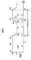
- the present invention includes a postage printing module 1 positioned between an upstream module 2 and a downstream module 3.
- Upstream and downstream modules 2 and 3 can be any kinds of modules in an inserter output subsystem.
- the upstream module 2 could include a device for wetting and sealing an envelope flap.
- Downstream module 3 could be a module for sorting envelopes into appropriate output bins.
- Postage printing module 1, upstream module 2, and downstream module 3, all include transport mechanisms for moving envelopes along the processing flow path.
- the modules use sets of upper and lower rollers 10, 20, 30, 40, 70, and 80 called nips, between which envelopes are driven in the flow direction.
- rollers 10, 20, 30, 40, 70, and 80 are hard-nip rollers to minimize dither.
- the transport for module 1 may also be belts, or other known transport mechanisms.
- Print heads 50 and 60 are preferably located at or near the output end of the print transport portion of the postage printing module 1 (see locations D and E). To satisfy desired readability the print heads 50 and 60 should be capable of printing an indicia at a resolution of 200 dots per inch (dpi). In the preferred embodiment, the print heads 50 and 60 are drop-on-demand ink jet print heads capable of printing 200 dpi on media traveling at 80 ips (203 cm/s). Alternatively, the print heads 50 and 60 can be any type of print heads, including those using other digital or mechanical technology, which may benefit from printing at a rate less than the system velocity.
- print heads 50 or 60 In the preferred embodiment only one of print heads 50 or 60 is in use at a given time. Typically, one of the print heads, for example 50, will be used to print indicia on the stream of envelopes. When it is time for print head 50 to undergo a maintenance cycle, rather than stop printing of indicia, print head 60 is brought into service to do the same job. Thus, only one print head operates at a time, with one print head operating as a back-up, and going into service when the primary undergoes a maintenance routine, or otherwise becomes unavailable. The reserve may then continue operation as the primary print head, and the former primary may become the reserve when the maintenance operation is complete. Alternately, the primary may be brought back into service when maintenance is complete, and the reserve returned to inactive status. Adjustments to the transport system of print module 1 in support using the two print heads 50 and 60 in this manner are discussed below.
- rollers 10, 20, 30, and 40 for postage printing module 1 are driven by motors 11, 21, 31, and 41.
- rollers 70 and 80 are driven by electric motors 12 and 13 respectively.
- Motors 11, 21, 31, 41, 12, and 13 are preferably independently controllable servo motors.
- Motors 12 and 13 in upstream and downstream modules 2 and 3 drive rollers 70 and 80 at a constant velocity, preferably at the desired nominal velocity for envelopes traveling in the system.
- upstream and downstream modules 2 and 3 will transport envelopes at 100 ips (254 cm/s) in the flow direction.
- the transports for module 1 may be driven in any known manner.
- the rollers 10, 20, 30, and 40 could be all geared to a single driving mechanism.
- the arrangement of separate control is preferred because it allows for more flexibility in controlling motion within the print module 1.
- Motors 11, 21, 31, and 41 drive rollers 10, 20, 30, and 40 in the postage printing module 1 at varying speeds in order to provide lower velocity printing capabilities.
- Postage printing module motors 11, 21, 31, and 41 are controlled by controller 14 which in turn receives sensor signals. Signals may be provided to the controller 14 from upstream sensor 15, downstream sensor 18, and trigger sensors 16 and 17. Sensors 15 and 18 are preferably used to detect the trailing edges of consecutive envelopes passing through the postage printing module 1, and to verify that the printing motion control adjustment only occurs while a single envelope under the control of the set of rollers performing the velocity change.
- Trigger sensor 16 determines that an envelope to be printed with an indicia is in the appropriate position to trigger the beginning of the print motion control scheme for print head 50, as described further below.
- trigger sensor 17 may be used for triggering the motion control scheme for print head 60.
- Sensors 15, 16, 17 and 18 are preferably photo sensors that are capable of detecting leading and trailing edges of envelopes. While four photo sensors are depicted in the embodiment of Fig. 2 , the system can be operated with as few as one photo sensor at an upstream location. The upstream single photo sensor would generate a signal upon deteting the presence of a lead or trail edge of an envelope. Subsequent to sensing the envelope, encoder pulses from the servo motors (11, 21, 31, 41 ) transporting the envelope could be counted, and the corresponding displacement can be accurately determined. Thus the controller 14 could trigger an action based on the sensing of an envelope edge, and then counting a predetermined quantity of pulses from the motor encoders. The preferred positioning of the sensors, and the utilization of signals received from the sensors are discussed in more detail below.
- the location of the output of the transport for upstream module 2 is location A.
- the location for the input to the print transport of postage printing module 1 is location B.
- An intermediary transport roller 20 is located at point C.
- Transports 30 and 40 for print heads 50 and 60 are located at points D and E.
- Point E is also the output of the print transport mechanism for postage printing module 1 .
- the input for the transport of downstream module 3 is location F.
- the modules may also include other rollers, or other types of transports, at other locations.
- consecutive distances between rollers 10, 20, 30, and 40 must be less than the shortest length envelope expected to be conveyed.
- the rollers 10, 20, 30, and 40 will preferably be spaced not more than 6.25" (15.9 cm) apart, so that an envelope can be handed off between sets of rollers without giving up control transporting the envelope at any time.
- the preferred embodiment is also designed to handle an envelope 10.375 inches (26.352 cm) long.
- Upstream sensor 15 is preferably located at or near location B, while downstream sensor 16 is preferably located at or near location E.
- Trigger sensors 17 and 18 are preferably located upstream from print heads 50 and 60 by a sufficient distance to permit deceleration of the print transport from the nominal transport velocity to the print velocity upon the detection of a lead envelope edge.
- the trigger sensors 17 and 18 may be located any distance upstream from the minimum deceleration point, even as far upstream as upstream sensor 15, so long as the motion control profile determined by controller 14 is adjusted accordingly.
- Controller 14 controls the motors 11, 21, 31, and 41 in accordance with a print motion control profile in order to achieve the goals of (1) reducing the speed of an envelope so that the lower velocity print heads 50 and 60 can print an indicia, (2) controlling the motion of the envelopes so that consecutive envelopes do not interfere with each other, and (3) allowing the printing duties to be shared between print heads 50 and 60 located at different positions along the transport path.
- the preferred motion control profile further allows that multiple envelopes may be handled within the print module 1 at a given time, and not interfere with one another, even when they are at different velocities, and without creating mismatches between print module 1 and the upstream and downstream modules 2 and 3.
- print motion control profile Depending on which of the print heads 50 or 60 is in use, different groupings of transport rollers (10, 20, 30, 40) in print module 1 will be used to perform the print motion control profile to decelerate envelopes to the print velocity and to return them to the transport velocity.
- a preferred embodiment of a print motion control profile for use with the present system is depicted in FIG. 3 , and described further below.
- print heads 50 and 60 are located at different locations along the transport path, the present system enables the speed adjustment motion profile to begin and end at different locations in the print module 1.
- transport rollers 10, 20, and 30 will be used to perform the speed adjustment, while roller 40 will remain at the constant transport velocity.
- roller 10 When print head 60 is in use, roller 10 operates at constant velocity, as if it were part of the upstream module 2. Meanwhile, rollers 20, 30, and 40 are grouped together to perform the motion profile.
- the groupings of the rollers will only remain in place so long as the rollers are needed as part of the group.
- Upstream members of the groups will return immediately to the transport velocity as soon as an envelope being printed passes from its control. For example, if print head 50 is in use, rollers 10, 20, and 30 will operate in unison as the envelope comes under the control of the group, However, the envelope may pass out of the control of roller 10, even while the printing operation, and corresponding transport motion control, are being carried out. When this happens, roller 10 leaves the uniformly controlled group and immediate accelerates back to transport velocity. Similarly, roller 20 would return immediately to the transport velocity when the envelope leaves its control. In this manner, the upstream rollers are more quickly ready to receive envelopes from upstream sources, even as print speed adjustments are still underway.
- a preferred method of controlling the velocity adjustment groups is to designate master and slave roller nips.
- roller 30 and motor 31
- roller 30 become a master for slave rollers 10 and 20 when an envelope comes under the complete control of the group.
- the envelopes leave rollers 10 and 20, they cease to be slaved to roller 30 and may be slaved to the roller 70 for upstream module 2.
- roller 40 was never part of the velocity adjustment grouping, and may be slaved to roller 80 of downstream module 3.
- the master roller for the velocity adjustment control group is roller 40.
- rollers 20 and 30 will be slaved to the master 40.
- roller 10 may be continuously slaved to roller 70 of upstream module 2.
- the envelope passes through the control group, and out of the control of rollers 20 and 30, they are preferably released from the master 40 and return to the transport velocity. In returning to the transport velocity, they may in turn be slaved to upstream roller 70.
- controller 14 is programmed to designate the appropriate individually controllable rollers and motors as masters and slaves based on positions of envelopes sensed by the sensors. Concurrently, the controller 14 is also providing the appropriate motion profile for the control group to allow reduced velocity printing.
- Initiation of the slaving of rollers and the print motion adjustment may be triggered by the controller when an envelope reaches a predetermined displacement downstream from sensor 15.
- the predetermined displacement is based on the distance between the trip photocell 15 and the print head 50, the deceleration rate, the indicia offset, upstream module velocity, print velocity, and settle time (before printing begins).
- the locations of the edges of envelopes may be detected based on the positioning of photocells at the exact locations. Alternatively, positions may be calculated by measuring encoder pulses from the servo motors, and adding the envelopes positional displacement from a known location of a previously tripped upstream sensor.
- Fig. 3 is an exemplary motion profile of master rollers 30 or 40 at locations D and E, depending on which of the print heads 50 or 60 is in use. Based on the criteria discussed above, rollers slaved to the master rollers will also perform portions of motion profile. Notations provide the translation distances of envelopes within the velocity adjustment control group of rollers for different intervals.
- the depicted profile is based on a system that is printing on envelopes 10.375" inches (26.352 cm) in length, that requires a maximum length printed indicia of 5" (12.7 cm).
- the nominal transport velocity is 100 ips (254 cm/s), and the print velocity is 80 ips (203 cm/s).
- the accelerations for adjusting speeds are 8.0 G's, or 3091 in/s 2 (7851 cm/s 2 ). For this embodiment, the throughput rate is 22,000 mailpieces per hour. At the nominal transport speed the period between envelopes is 164 ms.
- the print heads 50 and 60 are preferably located just downstream of nip roller sets 30 and 40. This location allows greater control at the print head location, and also minimizes the opportunity for errors relating to an envelope tail kick. Tail kick occurs when the trail edge of an envelope is not adequately constrained and comes into contact with a print head, thereby causing print head damage and failure.
- a lead edge of a first envelope reaches the output of the upstream module 2, at location A.
- the lead edge of the first envelope is at the most upstream roller of the velocity adjustment control group (location B or C).
- Sensors 15 and 16 can provide signals to controller 14 to prevent initiation of a change in velocity white an envelope is under the control of more than one module, or more than one control group.
- the first envelope is under the sole control of the control group of roller for print module 1, and the control group may slow down to allow the slower velocity printing.
- Controller 14 can begin the necessary deceleration by sensing the lead edge of the first envelope with the trigger sensor 16, 17.
- the deceleration can begin as a result of upstream sensor 15 detecting the position of the tail end of the first envelope.
- the three nips of the control group of the print module 1 initiate a predetermined deceleration to reach the desired print velocity, in this case 80 ips (203 cm/s).
- the control group master roller then operates at 80 ips (203 cm/s) to transport the envelope a predetermined distance while an indicia is printed on it.
- the print distance is five inches.
- the envelope is accelerated back to the transport speed. Slaved control group rollers upstream of the master roller, preferably return to the transport velocity of 100 ips (254 cm/s) prior to completion of the motion control profile of Fig. 3 , once the envelope has passed out of their control.
- the lead edge of the first envelope reaches the first nip downstream of the master nip.
- the first envelope is no longer under the exclusive control of the control group and variations in the print transport speed are not permissible.
- envelopes can be slowed for lower speed printing, but without having subsequent envelopes collide.
- the nominal distance between envelopes for the example described would be about 6.025 inches (15.303 cm) before entering the print module 1. After performing the print motion profile, the minimum distance between envelopes is reduced to 4.49 inches (11.40 cm). However, the nominal distance is restored as the subsequent envelope has the same motion profile performed on it, and the prior envelope travels away at the nominal travel velocity of 100 ips (254 cm/s). Accordingly, the throughput of the system remains intact.
- the exemplary motion profile described above complies with requirements necessary for a successful reduced velocity print operation.
- the velocity adjustment control group of nip in print module 1 must have total control of the envelope.
- the envelope cannot reside between nip rollers at location A or F during execution of the print motion control profile.
- the rate at which the print heads 50 and 60 print the indicia can be electronically or mechanically geared to the speed of the print transport in the print module 1. In such case, under circumstances where the print transport is operating outside of nominal conditions, a correct size and resolution print image can be generated.
- controller 14, print head 50 or 60, and the master roller servomotor 31 or 41 are geared to the same velocity and timing signals to provide that the transport and printing are always in synchronism.
- Another preferred embodiment of the present invention addresses a problem that occurs when the print module 1 is forced to deviate from the motion control profile depicted in Fig. 3 .
- a problem that occurs when the print module 1 is forced to deviate from the motion control profile depicted in Fig. 3 .
- upstream and downstream modules typically come to a halt in accordance with a uniform rapid linear deceleration profile.
- the postage printing modules have no mechanism for halting envelopes that are committed within the postage meter.
- additional paper jams and damaged envelopes commonly occur as the postage printing module forces envelopes against a halted downstream module.
- the print module 1 will also decelerate to a stop upon the occurrence of an exception event.
- exception events may include detection of jams, detection that mail pieces are out of order, or detection of equipment malfunctions.
- the print head 50 or 60 is geared to the master motor 31 or 41, then an envelope can be stopped anywhere in the print module 1 upon the occurrence of an exception event without damaging the envelopes, and without compromising the image to be printed on the envelope.
- print module 1 can be accelerated back to the velocities in accordance with the motion profile depicted in Fig. 3 .
- a uniform linear deceleration and acceleration during an exception condition is preferred for the upstream and downstream modules 2 and 3.
- a deceleration and acceleration having that same uniform linear profile may cause problems in print module 1. For example, if the print transport was about to reach point 203 in the motion profile of Fig. 3 when the exception condition occurred, the control group of the print transport could decelerate down to zero velocity in a linear fashion the same as modules 2 and 3.
- the envelope in the print module 1 will be closer to the downstream module than it would have been if the normal motion profile had been executed. This is because during the uniform deceleration, the print module 1 has essentially skipped a portion of the motion profile.
- the present invention maintains the expected displacements between consecutive documents by controlling the transport of envelopes in print module 1 as a function of the displacement positions of upstream and/or downstream modules 2 and 3.
- the variations in velocity that result from the stoppage and starting in an exception condition should not affect the relative spacing of the envelopes.
- the velocity variables will be eliminated, and positions of the transports expressed in terms of variable displacements and known constants.
- the desired displacements of the print module 1 must be describable in terms of the position of upstream or downstream modules. Also, the descriptions must be expressed in terms of the displacement relationships that would have resulted from the distinct segments in the motion profile.
- print module 1 must decelerate more quickly than upstream module 2 in order that the shortening of the gap between envelopes in those modules be preserved. To derive the appropriate displacement relationship for this segment of the print module 1 motion, the following symbols are defined:
- controller 14 of print module 1 can adjust the displacement of print module 1 when an envelope is present at a location where it normally would undergo the deceleration portion of the motion profile.
- the appropriate displacement relationship may change white the print module 1 is decelerating to a stop.
- an envelope that is slightly upstream of trigger sensor 16 or 17, and traveling at the transport velocity, may begin to stop in accordance with the displacement relationship described in equation [1], above.
- the envelope may reach the trigger position marked sensor 16 or 17.
- controller 14 will switch the displacement relationship to that described in equation [4] above.
- displacement may be controlled in accordance equation [5] above.
- the print head may begin printing a portion of the image on the envelope before it stops.
- the geared print head will also resume printing at the appropriate geared speed.
- a final segment of the motion profile is the acceleration of the envelope from the print velocity, back to the transport velocity.
- the displacement mapping relationship for this segment can be derived in the same way as for equation [4] above.
- a difference in the result being that this acceleration segment is causing an envelope in the print module 1 to increase its distance from a subsequent envelope in upstream module 2 .
- Displacement information for respective print, upstream, and downstream modules 1, 2, and 3 may typically be monitored via encoders in motors 11, 21, 31 , and 41 .
- the encoders register the mechanical movement of the module transports and report the displacements to controller 14 for appropriate use by controller 14 to maintain correct displacement mapping between the modules.
- Fig. 2 depicts an exemplary serial arrangement of two print heads, whereby one may be taken out of service while the other undergoes a maintenance cycle
- An alternative embodiment could utilize a parallel arrangement. Under this parallel arrangement, a flipper gate would be activated when the active print head is taken out of service. The flipper gate would redirect envelopes to a second parallel transport where the back-up print head prints indicia on envelopes.
- An exemplary parallel path system that would be suitable for use in this manner is depicted in co-pending European Patent Publication number 1391849, published February 25, 2004 and entitled PARALLEL PROCESSING HIGH SPEED PRINTING SYSTEM FOR AN INSERTING SYSTEM.
- documents being processed are envelopes. It should be understood that the present invention may be applicable for any kind of document on which printing is desired. Also a package or a parcel to which a printed image is applied as part of a processing system should also be considered to fall within the scope of the term "document" as used in this application.
Landscapes
- Engineering & Computer Science (AREA)
- Mechanical Engineering (AREA)
- Computer Security & Cryptography (AREA)
- Physics & Mathematics (AREA)
- General Physics & Mathematics (AREA)
- Accessory Devices And Overall Control Thereof (AREA)
- Delivering By Means Of Belts And Rollers (AREA)
- Devices For Checking Fares Or Tickets At Control Points (AREA)
- Ink Jet (AREA)
Description
- The present invention relates to an apparatus for printing postage value, or other information, on an envelope for use in a high speed mail processing and inserting system.
- Inserter systems such as those applicable for use with the present invention, are typically used by organizations such as banks, insurance companies and utility companies for producing a large volume of specific mailings where the contents of each mail item are directed to a particular addressee. Also, other organizations, such as direct mailers, use inserts for producing a large volume of generic mailings where the contents of each mail item are substantially identical for each addressee. Examples of such inserter systems are the 8 series, 9 series, and APS™ inserter systems available from Pitney Bowes Inc. of Stamford Connecticut, USA.
- In many respects, the typical inserter system resembles a manufacturing assembly line. Sheets and other raw materials (other sheets, enclosures, and envelopes) enter the inserter system as inputs. Then, a plurality of different modules or workstations in the inserter system work cooperatively to process the sheets until a finished mail piece is produced. The exact configuration of each inserter system depends upon the needs of each particular customer or installation.
- Typically, inserter systems prepare mail pieces by gathering collations of documents on a conveyor. The collations are then transported on the conveyor to an insertion station where they are automatically stuffed into envelopes. After being stuffed with the collations, the envelopes are removed from the insertion station for further processing. Such further processing may include automated closing and sealing the envelope flap, weighing the envelope, applying postage to the envelope, and finally sorting and stacking the envelopes.
-
US 2002/0040354 A1 describes a high-rate franking machine comprising means for printing postal indicia on a mailpiece and means for transporting this mailpiece along a mailpiece-conveying path, said printing means comprising, arranged side by side transversely to a direction D of advance of the mailpieces along said mailpiece-conveying path, a first printing module arranged in a first position (position of printing) above said mailpiece-conveying path and a second printing module arranged in a second position (position of maintenance/standby) set back with respect to said mailpiece-conveying path. The first printing module is associated with a first maintenance station and the second printing module is associated with a second maintenance station. -
EP 0 724 234 A2 describes a mail transport for a franking machine in which mail is fed toward a printing head by input rollers, is fed past the printing head by an impression roller and is ejected from the franking machine by ejection rollers. Drive to the input rollers is controlled to initially feed the mail at a transit speed toward the print head, to feed the mail item at a printing speed, during a printing period, lower than the transit speed and initially, in an ejection period after the printing period, to feed the mail item at the transit speed. When the mail item is released from the input rollers, the ejection rollers are driven to feed the mail item at a higher speed than the transit speed. - Current mail processing machines are often required to process up to 18,000 pieces of mail an hour. Such a high processing speed may require envelopes in an output subsystem to have a velocity in a range of 80-85 inches per second (ips) (203-216 cm/s) for processing. Consecutive envelopes will nominally be separated by a 200 ms time interval for proper processing while traveling through the inserter output subsystem.
- At such a high rate of speed, system modules, such as those for sealing envelopes and putting postage on envelopes, have very little time in which to perform their functions. If adequate control of spacing between envelopes is not maintained, the modules may not have time to perform their functions, envelopes may overlap, and jams and other errors may occur. In particular, postage meters are time sensitive components of a mail processing system. Meters must print a clear postal indicia on the appropriate part of the envelope to meet postal regulations. The meter must also have the time necessary to perform the necessary bookkeeping and calculations to ensure the appropriate funds are being stored and printed.
- A typical postage meter used with a conventional high speed mail processing system has a mechanical print head that imprints postage indicia on envelopes being processed. Such conventional postage metering technology is available on Pitney Bowes R150 and R156 mailing machines using model 6500 meters. The mechanical print head is typically comprised of a rotary drum that impresses an ink image on envelopes traveling underneath. Using mechanical print head technology, throughput speed for meters is limited by considerations such as the meter's ability to calculate postage and update postage meter registers, and the speed at which ink can be applied to the envelopes. In most cases, solutions using mechanical print head technology have been found adequate for providing the desired throughput of approximately five envelopes per second.
- However, use of existing mechanical print technology with high speed mail processing machines presents some challenges. First, some older mailing machines were not designed to operate at such high speeds for prolonged periods of time. Accordingly, solutions that allow printing to occur at lower speeds may be desirable in terms of enhancing long term mailing machine reliability.
- Another problem is that many existing mechanical print head machines are configured such that once an envelope is in the mailing machine, it is committed to be printed and translated to a downstream module, regardless of downstream conditions. As a result, if there is a paper jam downstream, the existing mailing machine component could cause even more collateral damage to envelopes within the mailing machine. At such high rates, jams and resultant damage may be more severe than at lower speeds. Accordingly, improved control and lowered printing speed, while maintaining high throughput rate in a mechanical print head mailing machine could provide additional advantages.
- Controlling throughput through the metering portion of a mail producing system is also a significant concern when using non-mechanical print heads. Many current mailing machines use digital printing technology to print postal indicia on envelopes. One form of digital printing that is commonly used for postage metering is thermal inkjet technology. Thermal inkjet technology has been found to be an effective method for generating images at 300 dpi on material translating up to 50 inches per second (ips) and 200 dpi at 80 ips. Thus, while thermal inkjet technology is recognized as useful, it is difficult to apply to high speed mail production systems that operate on mail pieces that are typically traveling in the range of up to 100 ips in such systems.
- As postage meters using digital print technology become more prevalent in the marketplace, it is important to find suitable substitutes for the mechanical print technology meters that have traditionally been used in high speed mail production systems. This need for substitution is particularly important as it is expected that postal regulations will require phasing out of older mechanical print technology meters, and replacement with more sophisticated meters, Ink jet digital print technology is now capable of printing a desired 200 dpi resolution on paper traveling at 80 ips., but has not yet been incorporated in the metering portions of high speed mail production systems.
- It is known that many standard ink jet print heads must be stopped occasionally in order to perform maintenance routines. In particular, "drop-on-demand" style ink jet print heads are known to require periodic maintenance. Maintenance may include a "print head wipe" that occurs approximately every 500 prints, and has a duration of approximately 3 seconds. Maintenance also may include a "print head purge" that occurs after approximately every 3000 prints, and has a duration of approximately 14 seconds. For an inserter operating at 18,000 pieces per hour, the wipe and purge activities would occur every 100 seconds and ten minutes respectively. These maintenance activities result in reduced throughput performance. For example, an inserter that would otherwise operate at 18,000 piece per hour, would be reduced to 17,000 pieces per hour as a result of purge and wipe print head maintenance.
- More expensive ink jet technology is available that does not require such frequent maintenance. For example, Scitex™ ink jet printers can run continuously, with no significant interruption. However, such continuous printers can be prohibitively expensive, and it is preferred that less expensive drop-on-demand ink jet print head technology can be used.
- Some systems that have been available from Pitney Bowes for a number of years address some issues relating to using a slower speed meter with a higher speed mail production system. These systems utilize mechanical print head R150 and R156 mailing machines using 6500 model postage meters installed on an inserter system. The postage meters operate at a slower velocity than that of upstream and downstream modules in the system. When an envelope reaches the postage meter module, a routine is initiated within the postage meter. Once the envelope is committed within the postage meter unit, this routine is carried out without regard to conditions outside the postage meter. The routine decelerates the envelope to a printing velocity. Then, the mechanical print head of the postage meters imprints an indicia on the envelope. After the indicia is printed, the envelope is accelerated back to close to the system velocity, and the envelope is transported out of the meter.
- Using the R150 or R156 mailing machines in this manner postage can be printed on envelopes at a lower print velocity. However, problems still occur for systems operating at higher velocities, such as 80 ips (203 cm/s). At this higher speed, the time interval between consecutive envelopes is so short that the R150 and R156 machines cannot reset itself in time to print an indicia on a second envelope. To solve this problem, Pitney Bowes has offered a solution for number of years utilizing two mailing machines arranged serially in the envelope transport path. A diagram of this prior art system is depicted in
Figure 1 . - In this serial mailing machine solution, envelopes are transported along
transport path 100. When a first of a series envelopes reaches the first serialmechanical mailing machine 101, the first envelope is decelerated for a printing operation bypostage meter 104. After printing is complete, the first envelope is carried away from the firstserial machine 101 viatransport 102 to the second serialmechanical mailing machine 103. - At the
second mailing machine 103, the first envelope is typically decelerated to the print velocity. However, since an indicia has already been printed on the first envelope, no printing operation is performed by thesecond postage meter 105. The first envelope is then accelerated back to the system velocity and carried out of the serial postage printing arrangement. - The motion control of deceleration and acceleration at the
second postage meter 105 without performing a print operation is done in order to maintain the displacements of consecutive envelopes in the system. Failure to subject subsequent envelopes to the same displacements may result in one envelope catching up to the other and causing a jam. - Following the first envelope, a second envelope arrives at the
first mailing machine 101. The second envelope is subjected to the deceleration and acceleration motion profile. In a high speed system, however, thefirst postage meter 104 may not have had time to reset to print another indicia. Accordingly, the second envelope passes through thefirst mailing machine 101 without a printing operation. The second envelope is then passed viatransport 102 to thesecond mailing machine 103 where it is again decelerated to the print velocity, This time, mailingmachine 103 does perform a printing operation and an indicia is printed on the second envelope bypostage meter 105.Mailing machine 103 then accelerates the envelope back to the system velocity, and the second envelope is carried away downstream. - In this manner, some of the shortcomings of conventional mailing machines are avoided by allowing the
serial mailing machines - Another problem with existing solution is that the conventional postage meters are inflexible in adjusting to conditions present in upstream or downstream meters. For example, if the downstream module is halted as a result of a jam, the postage meter will continue to operate on whatever envelope is within its control. This often results in an additional jam, and collateral damage, as the postage meter attempts to output the envelope to a stopped downstream module.
- According to a first aspect of the invention, there is provided a printing apparatus for use in a high velocity document processing system, the printing apparatus comprising: a transport path for conveying a series of documents; an upstream print head contiguous with the transport path to print on documents transported thereon; a downstream print head, downstream of the upstream print head, and contiguous with the transport path to print on documents transported thereon; and a controller for controlling a first one of the upstream or downstream print heads to print on transported documents, the controller operable for further switching to a second of the upstream or downstream print heads when the first one is out of service; the transport path further comprises an upstream transport for conveying documents at a transport velocity, a downstream transport for conveying documents at the transport velocity, a print transport located between the upstream transport and the downstream transport, the print transport arranged to be driven independently of the upstream transport and the downstream transport and comprising a plurality of individually controllable rollers; the controller for further controlling a roller group of less than all of the plurality of individually controllable rollers according to a predetermined motion profile, whereby under nominal conditions the roller group decelerates the print transport to a nominal print velocity prior to a printing operation in a first segment, maintains the nominal print velocity during the printing operation in a second segment, and accelerates the print transport back to the transport velocity after completion of the printing operation in a third segment; and the controller arranged to control the roller group to comprise of an upstream portion of the plurality of individually controllable rollers if the upstream print head is in use, and to comprise a downstream portion of the plurality of individually controllable rollers if the downstream print head is in use.
- According to a second aspect of the invention, there is provided a printing method for high velocity document processing, the printing method comprising: transporting a series of documents on a transport path; positioning an upstream print head contiguous with the transport path to print on documents transported thereon; positioning a downstream print head, downstream of the upstream print head, and contiguous with the transport path to print on documents transported thereon; controlling a first one of the upstream or downstream print heads to print on transported documents; and switching to a second of the upstream or downstream print heads for printing when the first one is out of service, the step of transporting further comprising: transporting a document at a transport velocity in an upstream transport to a print transport; transporting the document on the print transport; and transporting the document at the transport velocity in a downstream transport from the print transport; and including a further step, while the document is within the print transport during nominal system conditions, of controlling the velocity of the print transport in accordance with a motion profile, whereby the motion profile includes the steps of decelerating the document to a print velocity, maintaining the print velocity during the step of printing, and accelerating the document to the transport velocity after the step of printing is complete, the motion profile resulting in a relative displacement of the document with respect to upstream and downstream documents to vary during the motion profile; and performing the print transport motion profile with an upstream portion of the print transport when the upstream print head is in use, and with a downstream portion of the print transport when the downstream print head is in use, the upstream and downstream portions each comprising at least one transport mechanism different from the other.
- Further details of the present invention are provided in the accompanying drawings, detailed description and claims.
-
Figure 1 depicts a prior art inserter metering system using two mechanical meters in series. -
Figure 2 is a diagrammatic view of a postage printing module in relation to upstream and downstream modules. -
Figure 3 is a graphical representation of a print motion control profile for controlling the speed of envelopes in the postage printing module. - The present application describes a printing apparatus and method for use in a continuous high velocity document processing system. In the preferred embodiment, they printing system is used in connection with a postage meter for imprinting postal indicia on mail pieces. The print apparatus is preferably located at the downstream end of an inserter device for mass producing mail pieces.
- Within the postage printing module, a digital print mechanism is used at high speeds to create the postal indicia for the envelopes. Also, the motion of the envelope is controlled to allow continuous high speed envelope throughput, even if the postage printing device operates at a lower velocity than other parts of the system.
- Within the printing system, a transport path conveys a series of mail pieces at a print velocity. In the preferred embodiment, there are at least two print heads to perform printing operations. The print heads are preferably available ink jet print heads capable of printing at high resolution on documents traveling at high speed. During normal operation, only one print head is operating at a time. As mail pieces pass the print head at the print velocity, postal indicia are printed on them.
- However, continuous operation of the printing apparatus is potentially interrupted when the print head that is in use must stop in order to undergo a maintenance operation. Accordingly, in accordance with the present invention, the second print head goes into operation without interruption of the document processing flow.
- In the preferred embodiment, the print heads are in series. Thus, when one print head is taken out of service, the other one continues to print on documents in the same transport path. Because the second print head may be at a different location along the transport path, appropriate adjustments to the triggering of the print cycle are required.
- In an alternate embodiment, a parallel print head arrangement may be used. Under this alternate embodiment, a flipper switch redirects documents to a parallel transport path and a parallel print head, when the first one is out of service. In either embodiment, the activation of a second print head may also be triggered when the first print head is subject to a failure that prevents it from being used. Thus, it may not be necessary to halt operation of the mail production process.
- In a further preferred embodiment, a motion control scheme is used in the printing module to decelerate a mail piece for slower speed printing, and then returning the mail piece back to the higher system transport speed after printing. In this embodiment, different positions of the print heads may require that different portions of the print module transport act to effectuate the necessary print transport motion profile. Thus, when an upstream print head is in use, an upstream portion of the print module transport may be required to undergo the motion profile to account for the lower print speed. Likewise, when a downstream print head is in use, a downstream portion of the print module transport may be required for the motion profile.
- Accordingly, the system transports a first envelope at a nominal transport velocity to the postage printing module. The postage printing module receives the envelope at the nominal transport velocity. Based on predetermined criteria, one or the other of the at least two print heads is selected for printing the indicia on the envelope. If one print head is unavailable because of a failure, or because of a periodic maintenance sequence, then the other one is used. When the envelope has passed completely into the control of the postage printing module it is decelerated to a predetermined lower print velocity for printing an image of a predetermined length. After the printing is complete the envelope is accelerated back to the transport speed and transported to a downstream module. None of the intervals of deceleration, low print velocity, or acceleration may occur while an envelope in the postage printing module is also in the control of another module.
- This motion control is carried out by different transport elements in the print module depending on which print head is being used. Transport elements, such as rollers, are grouped together to act in unison in order to effectuate the motion control at the appropriate location in relation to the print head. Depending on which print head is used, a particular transport element may or may not be in the group performing the motion control. Some transport elements may be in more than one grouping.
- Deceleration in the motion control profile is activated by a sensor sensing the presence of the envelope at a trigger point. Further sensors at the upstream and downstream modules can be used to verify that no envelopes are under the shared control of the postage printing module and another module
- In another preferred embodiment, the print head is geared to operate in synchronism with the print transport, such that an image will not be distorted if there is a variation in print velocity.
- The preferred system and method also provide a way to ensure that correct displacement is maintained between subsequent envelopes under the control of the invention in the event of a stop and/or restart of the system resulting from an exception condition, such as an envelope jam. When an envelope is within the print transport during an exception condition, the envelope must be decelerated to a stop, so as not to create further jams or collateral damage. In most modules in the system, a linear uniform deceleration is preferred to minimize disruption of the desired spacing between mail pieces being processed.
- For the postage printing module, however, optimal performance using the present invention may require that deceleration not occur in the same uniform linear fashion as the rest of the system. Rather, deceleration is preferably controlled to maintain the relative displacement of envelopes in the postage printing module with respect to upstream and downstream modules, Because displacement varies in that module during normal operation, a uniform stopping and starting of the print module to mirror other modules will result in envelope spacing different than originally intended. Such changing in envelope gaps may result in further jams or misprocessing.
- For this reason, the deceleration and acceleration resulting from the exception condition is controlled to maintain relative displacements as those displacements would have been if the exception condition had not occurred. To achieve this result, a controller in the print module controls the displacement of the print module according to a predetermined algorithm. This algorithm relates displacements of the print module with other modules for segments of the motion profile as they would have been executed during normal operation. During the exception condition, deceleration and acceleration of the print module is thus controlled as a predetermined function, or set of functions, of the displacements in other transport modules. The appropriate function is determined as a result of the position of the envelope in the print module during the course of the exception condition.
- This displacement mapping functionality of the preferred embodiment operates cooperatively with the gearing of the print head mechanism to the print transport. In that preferred embodiment, stopping and restarting of the print module may not affect printing of an image on the envelope, even if a printing operation had already begun at the time of the stoppage.
- The principles discussed herein are also applicable to a system condition in which the system is stopped without the occurrence of any problems. For example, this embodiment may be applied in a situation where an operator simply wishes to turn off the system in order to take a lunch break, without waiting for the job to finish. Using this embodiment, the process of routine stopping and starting of the system is simplified, and the risk of errors occurring from such stopping and starting is reduced. It will be understood that these features. Stoppage conditions include errors and exception conditions, as well as routine starting and stopping.
- For the preferred embodiment of the present invention, it is desired that envelope printing throughput of 18,000 to 22,000 mail pieces per hour be achieved. To accomplish this goal, the transport velocity of the inserter system is typically 100 ips or greater. However, the preferred ink jet printing device to be used for printing a postage indicia is only capable of achieving a desired resolution of 200 dpi at a speed of 80 ips (203 cm/s). Such print heads are known to be available from printer manufacturers Canon, Brother and Hewlett-Packard. Accordingly, the present invention will be described primarily in regard to a system whereby the print module 1 is used to decelerate envelopes from 100 ips (245 cm/s), to 80 ips (203 cm/s) for printing, and back to 100 ips (254 cm/s) for further processing.
- As seen in
FIG. 2 , the present invention includes a postage printing module 1 positioned between anupstream module 2 and a downstream module 3. Upstream anddownstream modules 2 and 3 can be any kinds of modules in an inserter output subsystem. Typically theupstream module 2 could include a device for wetting and sealing an envelope flap. Downstream module 3 could be a module for sorting envelopes into appropriate output bins. - Postage printing module 1,
upstream module 2, and downstream module 3, all include transport mechanisms for moving envelopes along the processing flow path. In the depicted embodiment, the modules use sets of upper andlower rollers preferred embodiment rollers - Print heads 50 and 60 are preferably located at or near the output end of the print transport portion of the postage printing module 1 (see locations D and E). To satisfy desired readability the print heads 50 and 60 should be capable of printing an indicia at a resolution of 200 dots per inch (dpi). In the preferred embodiment, the print heads 50 and 60 are drop-on-demand ink jet print heads capable of printing 200 dpi on media traveling at 80 ips (203 cm/s). Alternatively, the print heads 50 and 60 can be any type of print heads, including those using other digital or mechanical technology, which may benefit from printing at a rate less than the system velocity.
- In the preferred embodiment only one of print heads 50 or 60 is in use at a given time. Typically, one of the print heads, for example 50, will be used to print indicia on the stream of envelopes. When it is time for
print head 50 to undergo a maintenance cycle, rather than stop printing of indicia,print head 60 is brought into service to do the same job. Thus, only one print head operates at a time, with one print head operating as a back-up, and going into service when the primary undergoes a maintenance routine, or otherwise becomes unavailable. The reserve may then continue operation as the primary print head, and the former primary may become the reserve when the maintenance operation is complete. Alternately, the primary may be brought back into service when maintenance is complete, and the reserve returned to inactive status. Adjustments to the transport system of print module 1 in support using the twoprint heads - The
rollers motors modules 2 and 3,rollers electric motors Motors Motors downstream modules 2 and 3drive rollers downstream modules 2 and 3 will transport envelopes at 100 ips (254 cm/s) in the flow direction. - Instead of independently controllable motors, the transports for module 1 may be driven in any known manner. For example, the
rollers -
Motors drive rollers printing module motors controller 14 which in turn receives sensor signals. Signals may be provided to thecontroller 14 from upstream sensor 15,downstream sensor 18, and triggersensors Sensors 15 and 18 are preferably used to detect the trailing edges of consecutive envelopes passing through the postage printing module 1, and to verify that the printing motion control adjustment only occurs while a single envelope under the control of the set of rollers performing the velocity change.Trigger sensor 16 determines that an envelope to be printed with an indicia is in the appropriate position to trigger the beginning of the print motion control scheme forprint head 50, as described further below. Similarly triggersensor 17 may be used for triggering the motion control scheme forprint head 60. -
Sensors Fig. 2 , the system can be operated with as few as one photo sensor at an upstream location. The upstream single photo sensor would generate a signal upon deteting the presence of a lead or trail edge of an envelope. Subsequent to sensing the envelope, encoder pulses from the servo motors (11, 21, 31, 41) transporting the envelope could be counted, and the corresponding displacement can be accurately determined. Thus thecontroller 14 could trigger an action based on the sensing of an envelope edge, and then counting a predetermined quantity of pulses from the motor encoders. The preferred positioning of the sensors, and the utilization of signals received from the sensors are discussed in more detail below. - Referring to
FIG.2 , the location of the output of the transport forupstream module 2 is location A. The location for the input to the print transport of postage printing module 1 is location B. Anintermediary transport roller 20 is located at point C. Transports 30 and 40 forprint heads - The modules may also include other rollers, or other types of transports, at other locations. To maintain control over envelopes traveling through the system, consecutive distances between
rollers rollers - Upstream sensor 15 is preferably located at or near location B, while
downstream sensor 16 is preferably located at or near locationE. Trigger sensors print heads trigger sensors controller 14 is adjusted accordingly. -
Controller 14 controls themotors downstream modules 2 and 3. - Depending on which of the print heads 50 or 60 is in use, different groupings of transport rollers (10, 20, 30, 40) in print module 1 will be used to perform the print motion control profile to decelerate envelopes to the print velocity and to return them to the transport velocity. A preferred embodiment of a print motion control profile for use with the present system is depicted in
FIG. 3 , and described further below. - Because print heads 50 and 60 are located at different locations along the transport path, the present system enables the speed adjustment motion profile to begin and end at different locations in the print module 1. Thus, when
print head 50 is in use,transport rollers roller 40 will remain at the constant transport velocity. - When
print head 60 is in use,roller 10 operates at constant velocity, as if it were part of theupstream module 2. Meanwhile,rollers - As a further enhancement to the performance of the system, the groupings of the rollers will only remain in place so long as the rollers are needed as part of the group. Upstream members of the groups will return immediately to the transport velocity as soon as an envelope being printed passes from its control. For example, if
print head 50 is in use,rollers roller 10, even while the printing operation, and corresponding transport motion control, are being carried out. When this happens,roller 10 leaves the uniformly controlled group and immediate accelerates back to transport velocity. Similarly,roller 20 would return immediately to the transport velocity when the envelope leaves its control. In this manner, the upstream rollers are more quickly ready to receive envelopes from upstream sources, even as print speed adjustments are still underway. - A preferred method of controlling the velocity adjustment groups is to designate master and slave roller nips. When
print head 50 is in use, roller 30 (and motor 31) become a master forslave rollers rollers roller 70 forupstream module 2. For this example,roller 40 was never part of the velocity adjustment grouping, and may be slaved toroller 80 of downstream module 3. - When
print head 60 is in use, the master roller for the velocity adjustment control group isroller 40. When an envelope enters the control of the control group,rollers 20 and 30 will be slaved to themaster 40. In this situation,roller 10 may be continuously slaved toroller 70 ofupstream module 2. As the envelope passes through the control group, and out of the control ofrollers 20 and 30, they are preferably released from themaster 40 and return to the transport velocity. In returning to the transport velocity, they may in turn be slaved toupstream roller 70. - Accordingly,
controller 14 is programmed to designate the appropriate individually controllable rollers and motors as masters and slaves based on positions of envelopes sensed by the sensors. Concurrently, thecontroller 14 is also providing the appropriate motion profile for the control group to allow reduced velocity printing. - Initiation of the slaving of rollers and the print motion adjustment may be triggered by the controller when an envelope reaches a predetermined displacement downstream from sensor 15. The predetermined displacement is based on the distance between the trip photocell 15 and the
print head 50, the deceleration rate, the indicia offset, upstream module velocity, print velocity, and settle time (before printing begins). For control purposes, the locations of the edges of envelopes may be detected based on the positioning of photocells at the exact locations. Alternatively, positions may be calculated by measuring encoder pulses from the servo motors, and adding the envelopes positional displacement from a known location of a previously tripped upstream sensor. - In the preferred embodiment depicted in
Fig. 2 , the following distances between components has been found to most effectively handle the expected range of envelope sizes: - A to B, 3.7 inches (9.40 cm);
- B to C, 3.9 inches (9.91 cm);
- C to D, 3.9 inches (9.91 cm);
- D to E, 6.25 inches (15.9 cm); and
- E to F, 6.1 inches (15.5 cm).
-
Fig. 3 is an exemplary motion profile ofmaster rollers 30 or 40 at locations D and E, depending on which of the print heads 50 or 60 is in use. Based on the criteria discussed above, rollers slaved to the master rollers will also perform portions of motion profile. Notations provide the translation distances of envelopes within the velocity adjustment control group of rollers for different intervals. The depicted profile is based on a system that is printing on envelopes 10.375" inches (26.352 cm) in length, that requires a maximum length printed indicia of 5" (12.7 cm). The nominal transport velocity is 100 ips (254 cm/s), and the print velocity is 80 ips (203 cm/s). The accelerations for adjusting speeds are 8.0 G's, or 3091 in/s2 (7851 cm/s2). For this embodiment, the throughput rate is 22,000 mailpieces per hour. At the nominal transport speed the period between envelopes is 164 ms. - The print heads 50 and 60 are preferably located just downstream of nip roller sets 30 and 40. This location allows greater control at the print head location, and also minimizes the opportunity for errors relating to an envelope tail kick. Tail kick occurs when the trail edge of an envelope is not adequately constrained and comes into contact with a print head, thereby causing print head damage and failure.
- At
point 201 on the profile, a lead edge of a first envelope reaches the output of theupstream module 2, at location A. In this exemplary profile, there is no envelope to be printed in the cycle before the first envelope. After crossing between the gap between the module transports, atpoint 202 the lead edge of the first envelope is at the most upstream roller of the velocity adjustment control group (location B or C). Atpoint 202 there can be no unilateral change in velocity of the print module transport by the control group.Sensors 15 and 16 can provide signals tocontroller 14 to prevent initiation of a change in velocity white an envelope is under the control of more than one module, or more than one control group. - At
point 203 on the motion profile, the first envelope is under the sole control of the control group of roller for print module 1, and the control group may slow down to allow the slower velocity printing.Controller 14 can begin the necessary deceleration by sensing the lead edge of the first envelope with thetrigger sensor - After
point 203, the three nips of the control group of the print module 1 initiate a predetermined deceleration to reach the desired print velocity, in thiscase 80 ips (203 cm/s). The control group master roller then operates at 80 ips (203 cm/s) to transport the envelope a predetermined distance while an indicia is printed on it. In this exemplary embodiment the print distance is five inches. After the predetermined print distance has been completed, the envelope is accelerated back to the transport speed. Slaved control group rollers upstream of the master roller, preferably return to the transport velocity of 100 ips (254 cm/s) prior to completion of the motion control profile ofFig. 3 , once the envelope has passed out of their control. - After the motion control profile has been complete, such as at
point 205, the lead edge of the first envelope reaches the first nip downstream of the master nip. At this point in time, the first envelope is no longer under the exclusive control of the control group and variations in the print transport speed are not permissible. - Using the motion profile depicted in
Fig. 3 , and the control scheme discussed previously, envelopes can be slowed for lower speed printing, but without having subsequent envelopes collide. The nominal distance between envelopes for the example described would be about 6.025 inches (15.303 cm) before entering the print module 1. After performing the print motion profile, the minimum distance between envelopes is reduced to 4.49 inches (11.40 cm). However, the nominal distance is restored as the subsequent envelope has the same motion profile performed on it, and the prior envelope travels away at the nominal travel velocity of 100 ips (254 cm/s). Accordingly, the throughput of the system remains intact. - The exemplary motion profile described above complies with requirements necessary for a successful reduced velocity print operation. As mentioned above, when print speed adjustment is performed on an envelope, the velocity adjustment control group of nip in print module 1 must have total control of the envelope. For example, the envelope cannot reside between nip rollers at location A or F during execution of the print motion control profile.
- In a further preferred embodiment of the present invention, to ensure accurate printing, the rate at which the print heads 50 and 60 print the indicia can be electronically or mechanically geared to the speed of the print transport in the print module 1. In such case, under circumstances where the print transport is operating outside of nominal conditions, a correct size and resolution print image can be generated. In the electronic version of this preferred embodiment,
controller 14,print head master roller servomotor - Another preferred embodiment of the present invention addresses a problem that occurs when the print module 1 is forced to deviate from the motion control profile depicted in
Fig. 3 . For example, in a conventional inserter system, when an envelope jam occurs downstream from the postage printing module, upstream and downstream modules typically come to a halt in accordance with a uniform rapid linear deceleration profile. Unfortunately, in conventional inserter systems, the postage printing modules have no mechanism for halting envelopes that are committed within the postage meter. As a result, additional paper jams and damaged envelopes commonly occur as the postage printing module forces envelopes against a halted downstream module. - To address this problem, in the preferred embodiment of the present invention the print module 1 will also decelerate to a stop upon the occurrence of an exception event. Such exception events may include detection of jams, detection that mail pieces are out of order, or detection of equipment malfunctions. If the
print head master motor Fig. 3 . - A uniform linear deceleration and acceleration during an exception condition is preferred for the upstream and
downstream modules 2 and 3. However, a deceleration and acceleration having that same uniform linear profile may cause problems in print module 1. For example, if the print transport was about to reachpoint 203 in the motion profile ofFig. 3 when the exception condition occurred, the control group of the print transport could decelerate down to zero velocity in a linear fashion the same asmodules 2 and 3. However, after the exception condition has been cleared, the envelope in the print module 1 will be closer to the downstream module than it would have been if the normal motion profile had been executed. This is because during the uniform deceleration, the print module 1 has essentially skipped a portion of the motion profile. During this "skipped" portion, it was intended that the envelope decelerate to the print velocity. A result of that deceleration would have been an increase in the gap with a downstream envelope and a decrease in a gap with an upstream envelope. A uniform shutdown profile for all modules interferes with this planned variation in gap sizes. - Accordingly, the present invention maintains the expected displacements between consecutive documents by controlling the transport of envelopes in print module 1 as a function of the displacement positions of upstream and/or
downstream modules 2 and 3. Thus, the variations in velocity that result from the stoppage and starting in an exception condition should not affect the relative spacing of the envelopes. In the equations provided below for determining the appropriate displacement relationship, the velocity variables will be eliminated, and positions of the transports expressed in terms of variable displacements and known constants. - To achieve this desired result, the desired displacements of the print module 1, as they would have resulted from performance of the motion profile under nominal conditions, must be describable in terms of the position of upstream or downstream modules. Also, the descriptions must be expressed in terms of the displacement relationships that would have resulted from the distinct segments in the motion profile.
- For example, for the portion of the motion profile where the print module 1 should transport the envelope at the transport velocity, there should be a one-to-one correspondence in the displacements produced by an
upstream module 2 and print module 1. Thus, if an exception condition occurs while an envelope is at a location within the print module 1 where it would normally be traveling at the transport velocity, then the deceleration of the print module 1 during an exception condition will mirror that of theupstream module 2. For this exemplary situation, the equation relating the displacement position of the print module 1, "P1," to the displacement position of theupstream module 2, "P2," will be:
- If the envelope is located at a position where it would normally be subject to deceleration in preparation for a printing operation, then, during an exception condition, print module 1 must decelerate more quickly than
upstream module 2 in order that the shortening of the gap between envelopes in those modules be preserved. To derive the appropriate displacement relationship for this segment of the print module 1 motion, the following symbols are defined: - v = velocity of the print module 1 transport;
- vtransport = the transport velocity for the system, (nominally 100 ips (254 cm/s));
- vprint = the print velocity for print module 1 during the printing segment of the motion profile (nominally 80ips (203 cm/s));
- a1 = acceleration that print module 1 would normally undergo in the deceleration segment of the motion profile (deceleration being a negative value acceleration) (nominally -1500 in/sec (3810 cm/s));
- a2 = acceleration that print module 1 would normally undergo in the acceleration segment of the motion profile (nominally 1500 in/sec (3810 cm/s));
- Pdecel = the displacement that print module 1 normally undergoes during the deceleration portion of the motion profile (nominally 0.58 inches (1.47 cm)); and
- Paccel = the displacement that print module 1 normally undergoes during the acceleration portion of the motion profile (nominally 0.58 inches (1.47 cm)).
- During normal operation in accordance with the motion profile, the displacement position, P1, of the print module 1, starting at the beginning of the deceleration segment, is described according to the equation:

- An expression can also be derived relating the velocity, v, of print modules 1 as a function of the displacement position, P2, of
upstream module 2, during normal operation of the deceleration portion of the motion profile:
- Thus, an equation relating P1 and P2, independent of instantaneous velocities, is derived by substituting the value of "v" derived in equation [3] into equation [2]. Performing this substitution, displacement relationship between print module 1 with
upstream module 2, for the deceleration segment of the motion profile is:
- Using this relationship in equation [4],
controller 14 of print module 1 can adjust the displacement of print module 1 when an envelope is present at a location where it normally would undergo the deceleration portion of the motion profile. - The next segment of the motion profile for discussion is the printing portion. During that segment the envelope is transported at a constant velocity. vprint. Accordingly, for that segment, the relative displacements that would be seen in
upstream module 2 and print module 1 would be described as a fixed ratio. This relationship is described by the following equation:
- It should be noted that the appropriate displacement relationship may change white the print module 1 is decelerating to a stop. For example, an envelope that is slightly upstream of
trigger sensor sensor trigger sensor controller 14 will switch the displacement relationship to that described in equation [4] above. Thus, as many different displacement relationships may be utilized as may be necessitated by the positions reached by the envelope during the deceleration process. Thus, if the deceleration were protracted to reach a location where a printing segment was intended, then displacement may be controlled in accordance equation [5] above. Also, based on the gearing of theprint head motor - A final segment of the motion profile is the acceleration of the envelope from the print velocity, back to the transport velocity. The displacement mapping relationship for this segment can be derived in the same way as for equation [4] above. A difference in the result being that this acceleration segment is causing an envelope in the print module 1 to increase its distance from a subsequent envelope in
upstream module 2. Accordingly, the displacement relationship when an envelope is at the acceleration motion profile segment during a stopping or restarting condition is as follows:
- Displacement information for respective print, upstream, and
downstream modules 1, 2, and 3 may typically be monitored via encoders inmotors controller 14 for appropriate use bycontroller 14 to maintain correct displacement mapping between the modules. - The preferred embodiment depicted in
Fig. 2 , depicts an exemplary serial arrangement of two print heads, whereby one may be taken out of service while the other undergoes a maintenance cycle, An alternative embodiment could utilize a parallel arrangement. Under this parallel arrangement, a flipper gate would be activated when the active print head is taken out of service. The flipper gate would redirect envelopes to a second parallel transport where the back-up print head prints indicia on envelopes. An exemplary parallel path system that would be suitable for use in this manner is depicted in co-pending European Patent Publication number1391849, published February 25, 2004 and entitled PARALLEL PROCESSING HIGH SPEED PRINTING SYSTEM FOR AN INSERTING SYSTEM. - In this application, a preferred embodiment of the system has been described in which documents being processed are envelopes. It should be understood that the present invention may be applicable for any kind of document on which printing is desired. Also a package or a parcel to which a printed image is applied as part of a processing system should also be considered to fall within the scope of the term "document" as used in this application.
- The preferred embodiment was also described herein as including two print heads. It will be understood by one of ordinary skill in the art that the invention may utilize more than two print heads, and that nothing in this description is intended to limit the invention from using more than two.
- Although the invention has been described with respect to a preferred embodiment thereof, it will be understood by those skilled in the art that the foregoing and various other changes, omissions and deviations in the form and detail thereof may be made without departing from the scope of this invention.
Claims (25)
- A printing apparatus (1, 2, 3) for use in a high velocity document processing system, the printing apparatus comprising:a transport path for conveying a series of documents;an upstream print head (50) contiguous with the transport path to print on documents transported thereon;a downstream print head (60), downstream of the upstream print head (50), and contiguous with the transport path to print on documents transported thereon; anda controller (14) for controlling a first one of the upstream or downstream print heads (50, 60) to print on transported documents, the controller operable for further switching to a second of the upstream or downstream print heads (50, 60) when the first one is out of service;the transport path further comprises an upstream transport (70) for conveying documents at a transport velocity, a downstream transport (80) for conveying documents at the transport velocity, a print transport (10,20,30,40) located between the upstream transport (70) and the downstream transport (80), the print transport (10,20,30,40) arranged to be driven independently of the upstream transport (70) and the downstream transport (80) and comprising a plurality of individually controllable rollers (10,20,30,40);the controller (14) for further controlling a roller group of less than all of the plurality of individually controllable rollers (10,20,30,40) according to a predetermined motion profile, whereby under nominal conditions the roller group decelerates the print transport to a nominal print velocity prior to a printing operation in a first segment, maintains the nominal print velocity during the printing operation in a second segment, and accelerates the print transport back to the transport velocity after completion of the printing operation in a third segment; andthe controller arranged to control the roller group to comprise of an upstream portion (10,20,30) of the plurality of individually controllable rollers if the upstream print head (50) is in use, and to comprise a downstream portion (20,30,40) of the plurality of individually controllable rollers if the downstream print head (60) is in use.
- The printing apparatus of claim 1 wherein the documents are mail pieces and further comprising a postage meter coupled to the print heads (50,60), whereby postal indicia are printable on the mail pieces.
- The printing apparatus of claim 1 or 2 wherein the print heads (50,60) are ink jet print heads.
- The printing apparatus of any of claims 1-3 wherein the controller (14) is arranged periodically to take the print heads (50,60) that is in use out of service to perform maintenance operations.
- The printing apparatus of any of claims 1-3 wherein the controller (14) is arranged to switch from using the first print head (50) to the second print head (60) when a failure is detected in the first print head.
- The printing apparatus of claim 1 wherein one or more of the individually controlled rollers that are not part of the roller group when a given print head is in use are operated at the transport velocity.
- The printing apparatus of claim 1 wherein the controller (14) is operable to decelerate the roller group (10,20,30,40) controlled thereby to a stop upon the occurrence of a stoppage condition in the document processing system, the deceleration being controllable by the controller (14) in accordance with a predetermined algorithm to maintain a relative displacement of the roller group with respect to upstream or downstream transports to maintain the relative displacements that would have occurred under the predetermined motion profile under nominal conditions, the predetermined algorithm determining the displacement of the roller group as a function of displacement of upstream or downstream transports.
- The printing apparatus in accordance with claim 7 wherein the controller (14) is further operable to control the roller group to accelerate from a stop back to nominal condition upon the occurrence of a restart after the stoppage condition, the acceleration being controllable by the controller (14) in accordance with the predetermined algorithm to maintain the relative displacement of the roller group with respect to upstream or downstream transports to maintain the relative displacements that would have occurred under the predetermined motion profile under nominal conditions, the predetermined algorithm determining the displacement of the roller group as a function of displacement of upstream or downstream transports.
- The printing apparatus any of claims 1-8 wherein the print heads (50,60) are electronically or mechanically geared to the corresponding roller group so that variations in print transport velocity during a printing operation will not affect an image being printed.
- The printing apparatus of any of claims 8 or 9 wherein the predetermined algorithm for determining relative displacements includes a first function for accounting for changes in relative displacements that would have occurred during deceleration of the roller group in the first segment of the motion profile, a second function for accounting for changes in relative displacements that would have occurred during the reduced nominal print velocity of the second segment of the motion profile, and a third function for accounting for changes in relative displacements that would have occurred during acceleration of the print transport in the third segment of the motion profile, the appropriate of the first, second, and third functions being invokable by the controller (14) based on the position of a document in the roller group during the occurrence of the stoppage condition.
- The printing apparatus of any of claims 1-10 wherein the upstream portion and the downstream portion of the plurality of individually controllable rollers (10,20,30,40) include at least one same roller (20,30) and at least one different roller (10,40).
- The printing apparatus of claim 1 wherein the controller (14) is further operable to control an arrangement of the roller group whereby a member of the roller group leaves the roller group after an envelope passes downstream from the members control.
- The printing apparatus of claim 12 wherein the controller (14) is operable to control a velocity of the member that leaves the roller group after the envelope passes downstream from the members control to be the transport velocity.
- A printing method for high velocity document processing, the printing method comprising:transporting a series of documents on a transport path;positioning an upstream print head (50) contiguous with the transport path to print on documents transported thereon;positioning a downstream print head (60), downstream of the upstream print head (50), and contiguous with the transport path to print on documents transported thereon;controlling a first one of the upstream or downstream print heads (50, 60) to print on transported documents; andswitching to a second of the upstream or downstream print heads (50, 60) for printing when the first one is out of service,the step of transporting further comprising:transporting a document at a transport velocity in an upstream transport (70) to a print transport (1);transporting the document on the print transport (1); andtransporting the document at the transport velocity in a downstream transport (80) from the print transport (1);and including a further step, while the document is within the print transport (1) during nominal system conditions, of controlling the velocity of the print transport (1) in accordance with a motion profile, whereby the motion profile includes the steps of decelerating the document to a print velocity, maintaining the print velocity during the step of printing, and accelerating the document to the transport velocity after the step of printing is complete, the motion profile resulting in a relative displacement of the document with respect to upstream and downstream documents to vary during the motion profile; andperforming the print transport motion profile with an upstream portion (10,20,30) of the print transport when the upstream print head (50) is in use, and with a downstream portion (20,30,40) of the print transport when the downstream print head (60) is in use, the upstream and downstream portions each comprising at least one transport mechanism (10,40) different from the other.
- The printing method of claim 14 further comprising printing postal indicia on mail pieces by coupling a postage meter to the print heads (50,60).
- The printing method of any of claims 14 or 15 wherein the step of printing comprises ink jet printing.
- The printing method of any of claims 14-16 further comprising periodically removing the print heads (50,60) that is in use out of service and performing maintenance operations on the print head.
- The printing method of claim 15 wherein further including switching from using the first print head (50) to the second print head (60) when a failure is detected in the first print head (50).
- The printing method of any of claims 14-18 further comprising detecting a document approaching the upstream or downstream print head (50,60), triggering the upstream or downstream print heads (50,60) based on a predetermined interval subsequent to detecting the document, and adjusting the predetermined interval depending on which of the upstream or downstream print heads (50,60) is in use to account for the different locations of the upstream and downstream print heads (50,60).
- The method of claim 14, wherein upon the occurrence of a stoppage condition while the document is within the print transport (1), further including the steps of:modifying the motion profile by stopping the document within the print transport (1) during a stoppage condition,decelerating the document to a stop, the step of decelerating to the stop including the step of maintaining the relative displacement of the document on the print transport (1) with respect to upstream and downstream documents, the step of maintaining the relative displacement including controlling the deceleration according to a predetermined algorithm describing relative displacement between documents as such displacement would have occurred under the motion profile under nominal conditions, the predetermined algorithm determining the displacement of the print transport (1) as a function of displacement of upstream or downstream transports (70,80).
- The printing method in accordance with claim 20 further comprising the steps of:restarting the print transport (1) while the document is within the print transport (1) during the stoppage condition, the step of restarting including the step of accelerating the document from the stop to a velocity of the motion profile, the step of accelerating including the step of maintaining the relative displacement of the document on the print transport (1) with respect to upstream and downstream documents, the step of maintaining the relative displacement including controlling the acceleration according to the predetermined algorithm.
- The printing method of any of claims 14-21 including the step of electronically or mechanically gearing the printing step to the print transport motion so that variations in print transport velocity during the printing step will not affect the image being printed.
- The printing method claim 21 wherein the predetermined algorithm for determining relative displacements including a first function accounting for changes in relative displacements that would have occurred during deceleration of the print transport in the first segment of the motion profile. a second function accounting for changes in relative displacements that would have occurred during the reduced nominal print velocity of the second segment of the motion profile, and a third function accounting for changes in relative displacements that would have occurred during acceleration of the print transport in the third segment of the motion profile, and
the method further including the step of invoking the appropriate of the first, second, and third functions based on the position of the document in the print transport (1) during the occurrence of the stoppage condition. - The printing method of claim 14 wherein upstream (10,20,30) and downstream (20,30,40) portions of the print transport (1) are comprised of a grouping of individually controllable rollers, the method further comprising:controlling the grouping of rollers whereby a member of the grouping leaves the grouping after an envelope passes downstream from the member's control, regardless of the motion profile.
- The printing method of claim 24 further comprising controlling a velocity of the member that leaves the grouping to be the transport velocity.
Applications Claiming Priority (4)
| Application Number | Priority Date | Filing Date | Title |
|---|---|---|---|
| US675362 | 1991-03-25 | ||
| US10/675,362 US6988842B2 (en) | 2003-09-30 | 2003-09-30 | Method and apparatus for continuous high speed digital metering using multiple print heads |
| US10/675,403 US6893175B2 (en) | 2003-09-30 | 2003-09-30 | Method and system for high speed digital metering |
| US675403 | 2003-09-30 |
Publications (3)
| Publication Number | Publication Date |
|---|---|
| EP1521218A2 EP1521218A2 (en) | 2005-04-06 |
| EP1521218A3 EP1521218A3 (en) | 2006-08-02 |
| EP1521218B1 true EP1521218B1 (en) | 2013-07-31 |
Family
ID=34316898
Family Applications (1)
| Application Number | Title | Priority Date | Filing Date |
|---|---|---|---|
| EP04023374.4A Expired - Lifetime EP1521218B1 (en) | 2003-09-30 | 2004-09-30 | Method and system for high speed digital metering |
Country Status (1)
| Country | Link |
|---|---|
| EP (1) | EP1521218B1 (en) |
Family Cites Families (4)
| Publication number | Priority date | Publication date | Assignee | Title |
|---|---|---|---|---|
| GB9501730D0 (en) | 1995-01-30 | 1995-03-22 | Neopost Ltd | Franking apparatus and mail transport thereof |
| US6322069B1 (en) * | 1999-03-12 | 2001-11-27 | Xerox Corporation | Interpaper spacing control in a media handling system |
| FR2814840B1 (en) | 2000-09-29 | 2002-12-27 | Neopost Ind | HIGH THROUGHPUT POSTAGE MACHINE |
| US6783290B2 (en) * | 2002-08-05 | 2004-08-31 | Pitney Bowes Inc. | Method and system for high speed digital metering using low velocity print technology |
-
2004
- 2004-09-30 EP EP04023374.4A patent/EP1521218B1/en not_active Expired - Lifetime
Also Published As
| Publication number | Publication date |
|---|---|
| EP1521218A2 (en) | 2005-04-06 |
| EP1521218A3 (en) | 2006-08-02 |
Similar Documents
| Publication | Publication Date | Title |
|---|---|---|
| EP1306336B1 (en) | Dynamic pitch correction for an output inserter subsystem | |
| EP0854445B1 (en) | Article transport apparatus | |
| EP1901237B1 (en) | Method and system for high speed digital metering using low velocity print technology | |
| US6106095A (en) | Mailing machine having registration of multiple arrays of print elements | |
| EP1490281B1 (en) | Controlling timing of mail pieces being processed by a mailing system | |
| US7040616B2 (en) | Method and system for high speed digital metering using overlapping envelopes | |
| US6988842B2 (en) | Method and apparatus for continuous high speed digital metering using multiple print heads | |
| US6893175B2 (en) | Method and system for high speed digital metering | |
| EP1391849B1 (en) | Parallel processing high speed printing system for an inserting system | |
| EP1521218B1 (en) | Method and system for high speed digital metering | |
| US6966711B2 (en) | Dynamic registration device for mailing system | |
| US5838346A (en) | Scanning printhead for printing on a moving medium | |
| EP1952995B1 (en) | Print interface system for a sheet handling device | |
| US6568671B1 (en) | Method and system for determining if a mailpiece has properly exited from a mailing machine | |
| EP1952996A2 (en) | Multi-function low profile print interface for a sheet handling device | |
| US20060122951A1 (en) | High speed postage metering device and method utilizing a single print head controller with multiple printing modules |
Legal Events
| Date | Code | Title | Description |
|---|---|---|---|
| PUAI | Public reference made under article 153(3) epc to a published international application that has entered the european phase |
Free format text: ORIGINAL CODE: 0009012 |
|
| AK | Designated contracting states |
Kind code of ref document: A2 Designated state(s): AT BE BG CH CY CZ DE DK EE ES FI FR GB GR HU IE IT LI LU MC NL PL PT RO SE SI SK TR |
|
| AX | Request for extension of the european patent |
Extension state: AL HR LT LV MK |
|
| RIN1 | Information on inventor provided before grant (corrected) |
Inventor name: SUSSMEIER, JOHN W. Inventor name: MILLER, JOHN P. Inventor name: STENGL, RICHARD F. Inventor name: LEITZ, JERRY Inventor name: YAP, ANTHONY E. |
|
| PUAL | Search report despatched |
Free format text: ORIGINAL CODE: 0009013 |
|
| AK | Designated contracting states |
Kind code of ref document: A3 Designated state(s): AT BE BG CH CY CZ DE DK EE ES FI FR GB GR HU IE IT LI LU MC NL PL PT RO SE SI SK TR |
|
| AX | Request for extension of the european patent |
Extension state: AL HR LT LV MK |
|
| 17P | Request for examination filed |
Effective date: 20070129 |
|
| AKX | Designation fees paid |
Designated state(s): DE FR GB |
|
| 17Q | First examination report despatched |
Effective date: 20100727 |
|
| GRAP | Despatch of communication of intention to grant a patent |
Free format text: ORIGINAL CODE: EPIDOSNIGR1 |
|
| RIN1 | Information on inventor provided before grant (corrected) |
Inventor name: STENGLI, RICHARD F. Inventor name: LEITZ, JERRY Inventor name: YAP, ANTHONY E. Inventor name: MILLER, JOHN P. Inventor name: SUSSMEIER, JOHN W. |
|
| GRAS | Grant fee paid |
Free format text: ORIGINAL CODE: EPIDOSNIGR3 |
|
| GRAA | (expected) grant |
Free format text: ORIGINAL CODE: 0009210 |
|
| AK | Designated contracting states |
Kind code of ref document: B1 Designated state(s): DE FR GB |
|
| REG | Reference to a national code |
Ref country code: GB Ref legal event code: FG4D |
|
| RIN1 | Information on inventor provided before grant (corrected) |
Inventor name: STENGLI, RICHARD F. Inventor name: LEITZ, JERRY Inventor name: SUSSMEIER, JOHN W. Inventor name: MILLER, JOHN P. Inventor name: YAP, ANTHONY E. |
|
| REG | Reference to a national code |
Ref country code: DE Ref legal event code: R096 Ref document number: 602004042886 Country of ref document: DE Effective date: 20130926 |
|
| PLBE | No opposition filed within time limit |
Free format text: ORIGINAL CODE: 0009261 |
|
| STAA | Information on the status of an ep patent application or granted ep patent |
Free format text: STATUS: NO OPPOSITION FILED WITHIN TIME LIMIT |
|
| 26N | No opposition filed |
Effective date: 20140502 |
|
| REG | Reference to a national code |
Ref country code: DE Ref legal event code: R097 Ref document number: 602004042886 Country of ref document: DE Effective date: 20140502 |
|
| REG | Reference to a national code |
Ref country code: FR Ref legal event code: PLFP Year of fee payment: 13 |
|
| REG | Reference to a national code |
Ref country code: FR Ref legal event code: PLFP Year of fee payment: 14 |
|
| REG | Reference to a national code |
Ref country code: FR Ref legal event code: PLFP Year of fee payment: 15 |
|
| REG | Reference to a national code |
Ref country code: DE Ref legal event code: R082 Ref document number: 602004042886 Country of ref document: DE Representative=s name: HOFFMANN - EITLE PATENT- UND RECHTSANWAELTE PA, DE Ref country code: DE Ref legal event code: R081 Ref document number: 602004042886 Country of ref document: DE Owner name: DMT SOLUTIONS GLOBAL CORP. (N.D.GES.D. STAATES, US Free format text: FORMER OWNER: PITNEY BOWES, INC., STAMFORD, CONN., US |
|
| REG | Reference to a national code |
Ref country code: GB Ref legal event code: 732E Free format text: REGISTERED BETWEEN 20191128 AND 20191204 |
|
| PGFP | Annual fee paid to national office [announced via postgrant information from national office to epo] |
Ref country code: GB Payment date: 20230927 Year of fee payment: 20 |
|
| PGFP | Annual fee paid to national office [announced via postgrant information from national office to epo] |
Ref country code: FR Payment date: 20230925 Year of fee payment: 20 Ref country code: DE Payment date: 20230927 Year of fee payment: 20 |
|
| REG | Reference to a national code |
Ref country code: DE Ref legal event code: R071 Ref document number: 602004042886 Country of ref document: DE |
|
| PG25 | Lapsed in a contracting state [announced via postgrant information from national office to epo] |
Ref country code: GB Free format text: LAPSE BECAUSE OF EXPIRATION OF PROTECTION Effective date: 20240929 |
|
| REG | Reference to a national code |
Ref country code: GB Ref legal event code: PE20 Expiry date: 20240929 |
|
| PG25 | Lapsed in a contracting state [announced via postgrant information from national office to epo] |
Ref country code: GB Free format text: LAPSE BECAUSE OF EXPIRATION OF PROTECTION Effective date: 20240929 |