EP1952015B1 - Pale d aérogénérateur à profil aérodynamique variable - Google Patents
Pale d aérogénérateur à profil aérodynamique variable Download PDFInfo
- Publication number
- EP1952015B1 EP1952015B1 EP05792070.4A EP05792070A EP1952015B1 EP 1952015 B1 EP1952015 B1 EP 1952015B1 EP 05792070 A EP05792070 A EP 05792070A EP 1952015 B1 EP1952015 B1 EP 1952015B1
- Authority
- EP
- European Patent Office
- Prior art keywords
- active elastic
- blade
- elastic member
- wind turbine
- shape
- Prior art date
- Legal status (The legal status is an assumption and is not a legal conclusion. Google has not performed a legal analysis and makes no representation as to the accuracy of the status listed.)
- Not-in-force
Links
- 239000012530 fluid Substances 0.000 claims description 88
- 238000000034 method Methods 0.000 claims description 37
- 238000009826 distribution Methods 0.000 claims description 31
- 230000033228 biological regulation Effects 0.000 claims description 24
- 230000008859 change Effects 0.000 claims description 19
- 125000004122 cyclic group Chemical group 0.000 claims description 18
- 230000001276 controlling effect Effects 0.000 claims description 13
- 101100129500 Caenorhabditis elegans max-2 gene Proteins 0.000 claims description 12
- 230000001419 dependent effect Effects 0.000 claims description 10
- 238000004891 communication Methods 0.000 claims description 8
- 238000013473 artificial intelligence Methods 0.000 claims description 5
- 238000009434 installation Methods 0.000 claims description 5
- 230000001105 regulatory effect Effects 0.000 claims description 4
- 230000003247 decreasing effect Effects 0.000 claims description 3
- 239000000835 fiber Substances 0.000 claims description 2
- 230000003287 optical effect Effects 0.000 claims description 2
- 239000003570 air Substances 0.000 description 12
- 239000007789 gas Substances 0.000 description 12
- 230000000694 effects Effects 0.000 description 11
- 230000009467 reduction Effects 0.000 description 9
- 230000007423 decrease Effects 0.000 description 7
- 238000005452 bending Methods 0.000 description 6
- 239000000463 material Substances 0.000 description 6
- 239000002520 smart material Substances 0.000 description 6
- 230000003044 adaptive effect Effects 0.000 description 5
- 238000010586 diagram Methods 0.000 description 5
- 230000002349 favourable effect Effects 0.000 description 5
- 239000007788 liquid Substances 0.000 description 5
- UJCHIZDEQZMODR-BYPYZUCNSA-N (2r)-2-acetamido-3-sulfanylpropanamide Chemical compound CC(=O)N[C@@H](CS)C(N)=O UJCHIZDEQZMODR-BYPYZUCNSA-N 0.000 description 4
- IJGRMHOSHXDMSA-UHFFFAOYSA-N Atomic nitrogen Chemical compound N#N IJGRMHOSHXDMSA-UHFFFAOYSA-N 0.000 description 4
- 241001669680 Dormitator maculatus Species 0.000 description 4
- 238000013461 design Methods 0.000 description 4
- 238000004519 manufacturing process Methods 0.000 description 4
- 238000005259 measurement Methods 0.000 description 3
- 238000005457 optimization Methods 0.000 description 3
- 230000002787 reinforcement Effects 0.000 description 3
- 230000004044 response Effects 0.000 description 3
- XLYOFNOQVPJJNP-UHFFFAOYSA-N water Substances O XLYOFNOQVPJJNP-UHFFFAOYSA-N 0.000 description 3
- XKRFYHLGVUSROY-UHFFFAOYSA-N Argon Chemical compound [Ar] XKRFYHLGVUSROY-UHFFFAOYSA-N 0.000 description 2
- 230000008901 benefit Effects 0.000 description 2
- 238000006243 chemical reaction Methods 0.000 description 2
- 238000002474 experimental method Methods 0.000 description 2
- 229910052757 nitrogen Inorganic materials 0.000 description 2
- 230000035945 sensitivity Effects 0.000 description 2
- 235000002756 Erythrina berteroana Nutrition 0.000 description 1
- 235000002753 Erythrina rubrinervia Nutrition 0.000 description 1
- 244000088811 Erythrina rubrinervia Species 0.000 description 1
- 239000000654 additive Substances 0.000 description 1
- 239000012080 ambient air Substances 0.000 description 1
- 238000013459 approach Methods 0.000 description 1
- 229910052786 argon Inorganic materials 0.000 description 1
- 230000015556 catabolic process Effects 0.000 description 1
- 239000011248 coating agent Substances 0.000 description 1
- 238000000576 coating method Methods 0.000 description 1
- 238000009833 condensation Methods 0.000 description 1
- 230000005494 condensation Effects 0.000 description 1
- 239000004020 conductor Substances 0.000 description 1
- 238000013016 damping Methods 0.000 description 1
- 238000006731 degradation reaction Methods 0.000 description 1
- 230000003111 delayed effect Effects 0.000 description 1
- 230000007613 environmental effect Effects 0.000 description 1
- 230000006872 improvement Effects 0.000 description 1
- 238000001802 infusion Methods 0.000 description 1
- 239000000203 mixture Substances 0.000 description 1
- 238000012544 monitoring process Methods 0.000 description 1
- 230000010355 oscillation Effects 0.000 description 1
- 230000001151 other effect Effects 0.000 description 1
- 239000003973 paint Substances 0.000 description 1
- 229920000642 polymer Polymers 0.000 description 1
- 230000035484 reaction time Effects 0.000 description 1
- 239000011347 resin Substances 0.000 description 1
- 229920005989 resin Polymers 0.000 description 1
- 238000000926 separation method Methods 0.000 description 1
- 239000002344 surface layer Substances 0.000 description 1
- 229920001169 thermoplastic Polymers 0.000 description 1
- 239000004416 thermosoftening plastic Substances 0.000 description 1
- 238000012546 transfer Methods 0.000 description 1
- 230000007704 transition Effects 0.000 description 1
Images


Classifications
-
- F—MECHANICAL ENGINEERING; LIGHTING; HEATING; WEAPONS; BLASTING
- F03—MACHINES OR ENGINES FOR LIQUIDS; WIND, SPRING, OR WEIGHT MOTORS; PRODUCING MECHANICAL POWER OR A REACTIVE PROPULSIVE THRUST, NOT OTHERWISE PROVIDED FOR
- F03D—WIND MOTORS
- F03D1/00—Wind motors with rotation axis substantially parallel to the air flow entering the rotor
- F03D1/06—Rotors
- F03D1/0608—Rotors characterised by their aerodynamic shape
- F03D1/0633—Rotors characterised by their aerodynamic shape of the blades
- F03D1/0641—Rotors characterised by their aerodynamic shape of the blades of the section profile of the blades, i.e. aerofoil profile
-
- F—MECHANICAL ENGINEERING; LIGHTING; HEATING; WEAPONS; BLASTING
- F03—MACHINES OR ENGINES FOR LIQUIDS; WIND, SPRING, OR WEIGHT MOTORS; PRODUCING MECHANICAL POWER OR A REACTIVE PROPULSIVE THRUST, NOT OTHERWISE PROVIDED FOR
- F03D—WIND MOTORS
- F03D7/00—Controlling wind motors
- F03D7/02—Controlling wind motors the wind motors having rotation axis substantially parallel to the air flow entering the rotor
- F03D7/022—Adjusting aerodynamic properties of the blades
- F03D7/024—Adjusting aerodynamic properties of the blades of individual blades
-
- F—MECHANICAL ENGINEERING; LIGHTING; HEATING; WEAPONS; BLASTING
- F03—MACHINES OR ENGINES FOR LIQUIDS; WIND, SPRING, OR WEIGHT MOTORS; PRODUCING MECHANICAL POWER OR A REACTIVE PROPULSIVE THRUST, NOT OTHERWISE PROVIDED FOR
- F03D—WIND MOTORS
- F03D7/00—Controlling wind motors
- F03D7/02—Controlling wind motors the wind motors having rotation axis substantially parallel to the air flow entering the rotor
- F03D7/04—Automatic control; Regulation
- F03D7/042—Automatic control; Regulation by means of an electrical or electronic controller
- F03D7/043—Automatic control; Regulation by means of an electrical or electronic controller characterised by the type of control logic
-
- F—MECHANICAL ENGINEERING; LIGHTING; HEATING; WEAPONS; BLASTING
- F05—INDEXING SCHEMES RELATING TO ENGINES OR PUMPS IN VARIOUS SUBCLASSES OF CLASSES F01-F04
- F05B—INDEXING SCHEME RELATING TO WIND, SPRING, WEIGHT, INERTIA OR LIKE MOTORS, TO MACHINES OR ENGINES FOR LIQUIDS COVERED BY SUBCLASSES F03B, F03D AND F03G
- F05B2240/00—Components
- F05B2240/20—Rotors
- F05B2240/30—Characteristics of rotor blades, i.e. of any element transforming dynamic fluid energy to or from rotational energy and being attached to a rotor
- F05B2240/301—Cross-section characteristics
-
- F—MECHANICAL ENGINEERING; LIGHTING; HEATING; WEAPONS; BLASTING
- F05—INDEXING SCHEMES RELATING TO ENGINES OR PUMPS IN VARIOUS SUBCLASSES OF CLASSES F01-F04
- F05B—INDEXING SCHEME RELATING TO WIND, SPRING, WEIGHT, INERTIA OR LIKE MOTORS, TO MACHINES OR ENGINES FOR LIQUIDS COVERED BY SUBCLASSES F03B, F03D AND F03G
- F05B2240/00—Components
- F05B2240/20—Rotors
- F05B2240/30—Characteristics of rotor blades, i.e. of any element transforming dynamic fluid energy to or from rotational energy and being attached to a rotor
- F05B2240/31—Characteristics of rotor blades, i.e. of any element transforming dynamic fluid energy to or from rotational energy and being attached to a rotor of changeable form or shape
- F05B2240/311—Characteristics of rotor blades, i.e. of any element transforming dynamic fluid energy to or from rotational energy and being attached to a rotor of changeable form or shape flexible or elastic
-
- F—MECHANICAL ENGINEERING; LIGHTING; HEATING; WEAPONS; BLASTING
- F05—INDEXING SCHEMES RELATING TO ENGINES OR PUMPS IN VARIOUS SUBCLASSES OF CLASSES F01-F04
- F05B—INDEXING SCHEME RELATING TO WIND, SPRING, WEIGHT, INERTIA OR LIKE MOTORS, TO MACHINES OR ENGINES FOR LIQUIDS COVERED BY SUBCLASSES F03B, F03D AND F03G
- F05B2270/00—Control
- F05B2270/30—Control parameters, e.g. input parameters
- F05B2270/32—Wind speeds
-
- Y—GENERAL TAGGING OF NEW TECHNOLOGICAL DEVELOPMENTS; GENERAL TAGGING OF CROSS-SECTIONAL TECHNOLOGIES SPANNING OVER SEVERAL SECTIONS OF THE IPC; TECHNICAL SUBJECTS COVERED BY FORMER USPC CROSS-REFERENCE ART COLLECTIONS [XRACs] AND DIGESTS
- Y02—TECHNOLOGIES OR APPLICATIONS FOR MITIGATION OR ADAPTATION AGAINST CLIMATE CHANGE
- Y02E—REDUCTION OF GREENHOUSE GAS [GHG] EMISSIONS, RELATED TO ENERGY GENERATION, TRANSMISSION OR DISTRIBUTION
- Y02E10/00—Energy generation through renewable energy sources
- Y02E10/70—Wind energy
- Y02E10/72—Wind turbines with rotation axis in wind direction
Definitions
- the invention relates to a wind turbine blade.
- the invention relates to a wind turbine blade having an aerodynamic profile, which profile is adjustable by deformation of an active elastic member arranged with access to the surface of the wind turbine blade at the profile.
- leading edge and/or the trailing edge by bending the profile upwards or downwards.
- WO 2004/088130 it was suggested to bend the leading edge zone and/or a trailing edge flap by means of a smart material or a hydraulic piston assembly.
- Part of the blade wall is made of a passive, flexible rubber, and during use the passive, flexible rubber is stretched to conform to the smart material or the hydraulic piston assembly.
- the rubber comprises isolated voids.
- active elastic member is herein meant that the thickness of the blade changes upon deformation of the elastic member.
- the thickness should typically be increased by at least 10% for at least one position at the active elastic member. It is preferred that the at least 10% is in addition to a possible change in thickness realised by optional bending of the tip region and/or the trailing edge region as this allows for a very fine tuning of the maximum lift coefficient at the active elastic member.
- the active elastic member may e.g. be manufactured completely or partially from a rubber-based material or from another polymer-based material.
- the expression arranged with access to the surface includes cases where the active elastic member is partially or completely covered by a surface layer, such as paint, a thermoplastic coating, an actuator means, such as a smart material, a lightning collector or a lightning conductor, etc.
- the active elastic member may be provided as a massive sheet or bulk member on a rigid complete or substantially complete blade wall part, for example when a traditional blade is upgraded by arranging an active elastic member thereon.
- the actuator means and/or a compartment for receiving a fluid may in this case be arranged between the original blade wall and the active elastic member.
- the active elastic member may also be provided as two or more sheets or massive sheet or bulk members connected to form one or more compartments or recesses therein.
- Such an active elastic member may likewise be arranged on a rigid complete or substantially complete blade wall part or on a more open structure, such as one or more rigid ribs or other rigid support structure.
- the aerodynamic shape of a wind turbine blade is typically formed by interpolation between a number of airfoils, i.e. cross sections of the blade orthogonal to the length of the blade, where each airfoil is optimized for a particular thickness to chord ratio, which again is dictated by the structural requirements of the blade.
- the present invention concerns wind turbine blades comprising at least one airfoil, which may change shape and aerodynamic properties during use by increasing the thickness of the airfoil.
- the wind turbine When the speed of the incoming wind is above a relatively low level, such as e.g. 11 m/s to 13 m/s, then the wind turbine reaches nominal power output and the operation of the wind turbine is more a matter of preventing or limiting damaging of the wind turbine than to optimize the energy output. This is traditionally realised by reducing the efficiency by pitching the blade so the angle of attack of the incoming wind is decreased and thereby decreasing the lift force on the blade.
- the speed of the incoming wind is very high, such as above 22 - 25 m/s, the wind turbine is brought to a halt. However, if the lift of the blade is reduced when the speed of the incoming wind is above the low level, then the window of operation may be extended.
- a reduction of the lift corresponds to a virtual reduction of the rotor radius, which is highly advantageous over traditional pitching or active stall, as the load on the blade is much more favourable and the strain of the blade is considerably reduced.
- the blades or even the individual blade may be optimised according to the instantly incoming wind experienced by the blade e.g. during a gust of wind or - if the incoming wind speed is measured in front of the wind turbine - the blades may be optimised even before e.g. a gust of wind arrives and hence greatly reduces the fatigue degradation of the blades considerably.
- the wind turbine blade according to the invention further comprises a blade tension means arranged in the blade to establish the tension of the blade.
- the blade tension means may advantageously be a strain gauge arranged in a blade wall or a spar of the blade as this allows for a very exact and very local measurement of the tension within the blade.
- the blade tension means comprises an optical or conducting fibre.
- the blade tension means is functionally connected, such as via mechanical means, via an electrical connection or via a wireless connection, to a control unit.
- the control unit is capable of controlling the shape of the active elastic member and may e.g. be a processor or a computer.
- the control unit may be connected to more than one wind turbine blade and is preferably integrated with the main control unit of the wind turbine.
- the control unit is arranged in the blade so that the individual blade acts autonomously.
- the wind turbine blade further comprises an anemometer arranged near the tip of the blade.
- the anemometer may be a range of means for measuring the incoming wind speed, the effective wind on one or more of the surfaces of the blade and/or the inflow angle of the wind on the blade.
- Advantageous examples are a laser anemometer for measuring the wind speed in front of the blade or a pito tube for measuring the inflow angle or the wind speed at the surface of the blade.
- the anemometer is functionally connected to a control unit. The control unit and connections are discussed above.
- chord line is the straight line between the leading edge and the trailing edge.
- Camber is the curve formed by connecting the points in the middle between the pressure side wall and the suction side wall. Hence, for an asymmetrical airfoil the camber will deviate from the chord line.
- deforming the active elastic member from the first shape to the second shape results in a shift in camber of an airfoil with the active elastic member
- the shift in chamber is a distance of at least 0.25% chord orthogonal to the chord line for a part of the airfoil corresponding to at least 10% of the chord line. This may e.g. be realised if the camber line is shifted from about 0-030% chord at 70% chord and 0.025% chord at 80% chord to about 0.027% chord at 70% chord and 0.021% chord at 80% chord, but the range of at least 10% of the chord line may also be broken into several intervals.
- deforming the active elastic member from the first shape to the second shape results in a shift in camber of an airfoil with the active elastic member, the shift in camber is a distance of at least 0.25% chord, preferably at least 0.30% chord orthogonal to the chord line for a part of the airfoil corresponding to at least 15% of the chord line.
- deforming the active elastic member from the first shape to the second shape results in a shift in chamber of an airfoil with the active elastic member, the shift in camber is a distance of at least 0.30% chord orthogonal to the chord line for a part of the airfoil corresponding to at least 10% of the chord line.
- the active elastic member is therefore typically arranged in an area between maximum thickness of the airfoil of the blade and the trailing edge, and the maximum thickness of the blade is hence not influenced by the active elastic member, whereas the shape between the maximum thickness and the trailing edge is adjusted and may be modified further during use.
- the active elastic member need not extend all the way to the trailing edge, but it was found that this arrangement was structurally favourable and that increasing the thickness of the trailing edge also influenced the size of the maximum lift coefficient considerably. It should be understood that e.g. the expression 'between the trailing edge and about 50% of the chord length from the leading edge' encompasses not only an active elastic member from exactly 50 chord-% to 100 chord-% but also active elastic members arranged completely or substantially within this part of the airfoil. Furthermore, it was found that an active elastic member between about 50 - 90% of the chord length from the leading edge was advantageous, and particularly an active elastic member between about 60 - 95% of the chord length from the leading edge was very advantageous.
- the active elastic member is arranged so that for a particular airfoil, the active elastic member is provided on the pressure side of the airfoil and the active elastic member begins at about 50 - 70% of the chord, preferably the active elastic member begins at about 55 - 65% of the chord, such as about 60% of the chord, and the active elastic member ends at about 80 - 90% of the chord, preferably the active elastic member ends at about 90 - 98% of the chord, such as about 95% of the chord.
- the active elastic member are particularly advantageous, since the camber may be changed in the area where it changes the lift of the airfoil very much.
- an active elastic member is arranged in the outermost 50 radius-% of the blade, such as in at least a part of the range between 50-90 radius-% of the blade or at least a part of the range between 60-95 radius-% of the blade, and arrangement of an active elastic member in the outermost 25 radius-% of the blade is even more advantageous.
- a change in the maximum lift coefficient in the outer part of the blade will have a similar effect with regard to reducing the fatigue load and energy production as a physical reduction of the radius of the rotor.
- the present invention of a wind turbine with wind turbine blade having an active elastic member may therefore be considered as having a variable effective aerodynamic rotor diameter and may therefore be considered an alternative for much more structurally complicated blades. This is particularly the case when the airfoil has a very low maximum lift coefficient such as a symmetrical airfoil or a substantially zero lift profile, when the active elastic member is in the shape with low maximum lift profile when the active elastic member is in the shape with low maximum lift coefficient.
- a wind turbine blade according to the invention comprises a plurality of active elastic members.
- the blade may comprise 2, 3, 4, 5, 6, 7, 8, 9, 10 or more active elastic members.
- Having a plurality of active elastic members improves the flexibility with regard to optimization of the profile of the blade. This is particularly important when the individual blade is continuously optimised with regard to the incoming wind or the tension of the blade.
- Preferably more than one of the plurality of elastic members are arranged with access to the pressure side of the blade. It is preferred that a majority of the active elastic members are arranged in an area between maximum thickness of airfoils of the blade and the trailing edge, as this is the area where the largest effect of active elastic members are realised as discussed elsewhere.
- a number of anemometers may advantageously be distributed lengthwise along the blade, so that each of the anemometers is arranged near a different of the plurality of active elastic members.
- the anemometers are functionally connected to a control unit capable of controlling the shape of the plurality of active elastic members individually.
- the control unit, connections and relevant types of anemometers are discussed above.
- At least two of the plurality of active elastic members are preferably arranged substantially end to end so that a first active elastic member extends from a second active elastic member in the length of the blade. This allows for the adjacent active elastic member to collaborate better and facilitates controlling of the members and forming of smooth transition from one active elastic member to another.
- At least two of the plurality of active elastic members are arranged side by side so that a first active elastic member extends from the second active elastic member substantially orthogonal to the length of the blade. This is particularly relevant for very large wind turbine blades where a single active elastic member or a plurality of active elastic member arranged end-to-end would be too slow to actuate.
- At least two of the plurality of active elastic members are arranged at least partially overlapping in the length of the blade and/or substantially orthogonal to the length of the blade.
- Overlapping active elastic member allows for a particularly easy control means for multi-step control of wind turbine blades, as the plurality of steps may be realised by a combination of on/off controlling steps of the individual active elastic members.
- the overlapping active elastic member is not identical in size. For example a 1/3 - 2/3 in size would allow for 4 stages, whereas a 1 ⁇ 2 - 1 ⁇ 2 would only allow for 3 stages.
- the size of the active elastic member should be chosen as a compromise between the size of the wind turbine blade, the size of the individual active elastic member and the number of active elastic members.
- the members should not be too small as this leads to a large number of active elastic members or only limited effect on the maximum lift coefficient.
- at least one of the plurality of active elastic members extends 2 to 30 meters in the length of the blade, preferably the active elastic member extends 5 to 20 meters. It is preferred that at least two of the plurality of active elastic members extend 8 to 15 meters in the length of the blade.
- the rotation speed is typically slower and larger active elastic member with slower reaction patterns are therefore acceptable.
- at least one of the plurality of active elastic members may advantageously extend 3% to 50% of the length of the wind turbine blade.
- at least one of the plurality of active elastic members extends 5% to 40% of the length of the wind turbine blade.
- at least two of the plurality of active elastic members extend 10% to 25% of the length of the wind turbine blade. This will typically keep the number of active elastic member reasonably.
- the wind turbine blade according to the invention further comprises a means to control the shape of the active elastic member individually.
- a means to control the shape of the active elastic member individually allows for a high degree of freedom with regard to optimization of the configuration of the active elastic member, i.e. which active elastic member to be non-deformed, which active elastic member to be partially deformed and which active elastic member to be completely deformed.
- individual control allows for radius dependent variation of the maximum lift coefficient so that the lift coefficient may be optimized with regard to local variation in the incoming wind, like e.g. gusts and/or variation due to the cyclic variation of the height above the ground.
- the means for control of the shape of active elastic members individually may e.g.
- a plurality of fluid distribution systems comprise one or more of a plurality of fluid distribution systems, a single fluid distribution system in combination with individually controllable valves for control of entering and/or exiting of fluid to the active elastic member, pressure gauges for each active elastic member, flow measurement devices for establishing transport of fluid into/from the active elastic member.
- the wind turbine blade according to the invention further comprises a means to control the shape of at least two of the active elastic members in combination. This allows for a more simple design with less sensors and/or distribution systems.
- second shape of the active elastic member is a relaxed state of the active elastic member.
- the relaxed state corresponds to the equilibrium state where e.g. the pressure of a control fluid corresponds to the external pressure.
- the equilibrium state of the active elastic member should in this embodiment be the situation where the maximum lift coefficient of the airfoil is less than the maximum possible value.
- the difference between the maximum lift coefficient, c L.max 1. of the airfoil with the active elastic member in the first shape and the maximum lift coefficient, c L.max 2. of the airfoil with the active elastic member in the second shape should be substantial to realise a wide operable range of incoming wind.
- the maximum lift coefficient, c L.max 1 is at least 10% larger than the maximum lift coefficient, c L.max 2 , of the airfoil with the active elastic member in the second shape.
- the maximum lift coefficient, c L.max 1 , of the airfoil with the active elastic member in the first shape is at least 15% larger than the maximum lift coefficient, c L.max 2 , of the airfoil with the active elastic member in the second shape.
- the maximum lift coefficient, c L.max 1 , of the airfoil with the active elastic member in the first shape is at least 20% larger than the maximum lift coefficient, c L.max 2 , of the airfoil with the active elastic member in the second shape. It is surprising that only these relatively small values of differences is sufficient to tune the blade properties but it was found that this allows for very fine tuning of the aerodynamic properties of the blade - particularly when a plurality of active elastic member is present.
- a wind turbine is typically operated in a range of angle of attack, ⁇ , below ⁇ max.
- the low values of ⁇ correspond to very heavy incoming winds and the high values of ⁇ correspond to operation in low winds near ⁇ max .
- the maximum lift coefficient of the airfoil may vary considerably within the inventive idea of the invention.
- the maximum lift coefficient with the active elastic member in the first shape, c L.max.1 is larger than 1.2 and/or the maximum lift coefficient of the airfoil with the active elastic member in the second shape, c L.max.2 , is below 1.0, where the maximum lift coefficient corresponds to Re in the range 1 - 10 millions and a two-dimensional flow passing a smooth profile surface.
- c L.max.1 is larger than 1.25 and/or c L.max , 2 is below 0.9, where the maximum lift coefficients correspond to Re in the range 1 - 10 millions and a two-dimensional flow passing a smooth profile surface. It should be observed that the actual in use conditions typically depart from these values and that these values should only be understood as what is considered to be favourable in wind tunnel experiments or modelling.
- the Reynolds experienced by the airfoil during use may vary considerably dependent on the radial position on the blade and the length of the blade. Typical values of the Reynolds number vary between 1 - 10 millions.
- the active elastic member comprises a compartment for receiving a fluid, or the active elastic member forms a compartment for receiving fluid in combination with a rigid part of the wind turbine blade, such as a part of a blade wall.
- the compartment is arranged so that the filling or emptying of the compartment leads to a change in the shape of the active elastic member; particularly, the compartment should be arranged so that the thickness of the blade at the active elastic member changes upon filling or emptying of the compartment.
- the wind turbine blade further comprises a receive valve to control the transport of fluid to the compartment.
- the receive valve is advantageously arranged near the compartment to be controlled, as this reduces the dead volume between the valve and the compartment.
- the receive valve is functionally connected to the compartment to be controlled.
- the valve may e.g. be a magnet valve or another valve operable in on/off mode or continuously by automation of a control means.
- the fluid may be received from a fluid distribution system or - if the fluid is air - optionally but not necessarily from the surface of the blade.
- the receive valve may advantageously be arranged near an end of the compartment towards the root of the blade as this allows the fluid to be move faster into the compartment due to the centripetal force acting upon the fluid during operation of the wind turbine.
- means, such as pumps, for moving the fluid through the fluid distribution system will typically take up some space and more space is available in the root section of the blade.
- the wind turbine blade further comprises a release valve to control the transport of fluid from the compartment.
- the release valve is advantageously arranged near the compartment to be controlled as this reduces the dead volume between the valve and the compartment.
- the release valve is functionally connected to the compartment to be controlled.
- the valve may e.g. be a magnet valve or another valve operable in on/off mode or continuously by automation of a control means.
- the fluid may be released to a fluid distribution system or - if the fluid is air - optionally but not necessarily to the surface of the blade.
- the release valve may advantageously be arranged near an end of the compartment towards the tip of the blade as this allows the fluid to move faster from the compartment due to the centripetal force acting upon the fluid during operation of the wind turbine.
- the blade further comprises a sensing means to further control the filling and emptying of the compartment by establishing the presence/absence of fluid in the compartment and/or the amount, e.g. the volume or pressure of the fluid present in the compartment.
- Preferred sensing means are a pressure gauge and a flow meter but other sensing means may also be suitable.
- the sensing means is functionally connected to the compartment and said sensing means being capable of establishing a volume of fluid in the compartment e.g. via the pressure of the fluid in the compartment or the flow of fluid to and/or from the compartment.
- the fluid distribution system is in communication with the compartment preferably via the receive valve and/or the release valve for controlling the transport of fluid to and/or from the compartment.
- the fluid distribution system may be a one-string system or a two-string system dependent on the number and operation of compartment(s).
- the fluid distribution system is in communication with a means for transporting the fluid.
- the means for transporting the fluid is also comprised by the wind turbine blade and typically arranged near the root of the blade.
- Preferred examples of means for transporting the fluid are a vacuum pump (for the fluid being a gas) and high pressure pump (for the fluid being a gas or a liquid).
- the fluid may be a gas or a liquid.
- Gas is preferred as the compressibility of gas is typically higher than for a liquid and a short response time may hence be achieved by simple means such as a pressure container. Furthermore, gas is relatively light and will hence not increase the weight of the blade as much as a fluid.
- the gas may be of any composition, such as e.g. nitrogen, argon or air. Air is preferred due to the readily availability and the low price. When ambient air is utilised, it is preferred to dehumidify the air prior to use to prevent condensation of water inside the system. Furthermore, air is advantageous in that it may be released from the surface of the blade without any environmental issues.
- Preferred liquids are water with suitable additives and other suitable hydraulic fluids.
- an active elastic member arranged on the pressure side between the airfoil between the maximum thickness of the airfoil and the trailing edge may be actuatable by other actuator means than fluid in a compartment.
- Such other actuator means may e.g. comprise smart materials, linear actuators, mechanical devices, pistons extendable by gas or fluid, piezo-electrical materials, etc.
- the alternative actuator means is typically connected to both a relatively rigid part of the airfoil and the active elastic member.
- Several of the alternative actuator means e.g. smart material and piezo-electrical material and some mechanical devices
- the invention concerns a wind turbine blade having a combination of an active elastic member and a flap, which flap is arranged near the trailing edge of the airfoil.
- the flap is active in the sense that it is actuatable by an actuator means between a first position and a second position, and the maximum lift coefficient of the airfoil with the flap in the first position is larger than the maximum lift coefficient of the airfoil with the flap in the second position.
- the actuation of the flap may be simultaneous to the actuation of the active elastic member but the actuation of the flap should at least be co-ordinated with the actuation of the active elastic member.
- the flap may be actuatable in one or more steps, where one of the steps corresponds to maximising of the maximum lift coefficient, or the flap may be actuatable continuously between a position where the maximum lift coefficient is maximised and a position where the flap is bended towards the suction side to yield a lower maximum lift coefficient.
- the flap extends from between 80 to 90% of the chord length from the leading edge to the trailing edge as this allows for the major part of the blade to be structurally rigid. It was found that when the flap extends from between about 85% of the chord length from the leading edge to the trailing edge, the maximum lift coefficient would be sufficiently adjusted by the actuation.
- the actuation of the flap may involve a partial rotation of a rigid part of the blade about a pivoting point or a more distributed bending of the trailing edge structure.
- the relaxed state of the flap i.e. the state in which the flap will be in the most unlikely event that the control systems should fail
- the second position where the flap is towards the suction side of the airfoil as compared to the first position of the flap.
- a wind turbine blade according to the invention comprises a plurality of flaps arranged near the trailing edge.
- the blade may comprise 2, 3, 4, 5, 6, 7, 8, 9, 10 or more flaps. Having a plurality of flaps improves the flexibility with regard to optimization of the profile of the blade during use. This is particularly important when the individual blade is continuously optimised with regard to the incoming wind or the tension of the blade.
- the size, i.e. the length in the longitudinal direction of the blade, of the flap should be chosen as a compromise between the size of the wind turbine blade, the size of the individual flap and a reasonable number of flaps.
- the flaps should not be too small as this leads to a large number of flaps, each with only a very limited effect on the maximum lift coefficient.
- at least one of the plurality of flaps extends 2 to 20 meters in the length of the blade, preferably the flap extends 5 to 15 meters. It is preferred that at least two of the plurality of flaps extend 5 to 15 meters in the length of the blade.
- the flap may or may not follow the size of the active elastic member but it is preferred that the ends of the flaps are arranged substantially at the ends of corresponding active elastic member as this is more structurally favourable and prevents twisting of the active elastic member.
- the rotation speed is typically slower, and large flaps with slower reaction patterns are therefore acceptable.
- at least one of the plurality of flaps may advantageously extend 3% to 50% of the length of the wind turbine blade.
- at least one of the plurality of flap members extends 5% to 40% of the length of the wind turbine blade.
- the plurality of flaps is arranged one extending another in the length direction of the blade and an elastic connector is arranged between adjacent flaps so that flaps form a continuous surface free from steps in the longitudinal direction of the blade.
- the extending flaps are separated by a short distance, such as 10 cm to 50 cm to give space for the elastic connector, and the elastic connector is connected to the end faces of both flaps and to the rigid part of the blade.
- actuator means of the flap may be actuatable in other ways, it is highly preferred that the actuator means of the flap is actuatable by a fluid and particularly by the same fluid as the active elastic members (if the active elastic member is actuatable by a fluid) as this allows for a more simple control system.
- the actuator means of the flap may advantageously be functionally connected to the fluid distribution system, which is in communication with an active elastic member. This allows for a more simple design of the fluid distribution system, it reduces the space requirements for the overall fluid distribution system and it reduces the overall weight of the system.
- actuator means to actuate the flap may comprise smart materials, which change shape upon change of a potential over the material, linear actuators, mechanical devices, pistons extendable by gas or fluid, piezo-electrical materials.
- actuators which only need an electrical signal to actuate, are advantageous due to relatively easy installation in the blade.
- the invention in another aspect, relates to a subunit for installation on a wind turbine blade.
- the wind turbine blade has a suction side and a pressure side, which sides are connected at a leading edge and a trailing edge to form a rigid blade surface.
- the subunit comprises an active elastic member with the properties and shape as discussed with regard to the one or more embodiments of other aspects of the present invention.
- the active elastic member is adapted with regard to shape and size to being connected to a rigid surface part of a wind turbine blade, so that during operation of a wind turbine comprising the wind turbine blade with the subunit installed thereon, the active elastic member is deformable from a first shape to a second shape. This may e.g.
- actuator means as discussed with regard to embodiments of one or more of the other aspects of the present invention, such as linear actuators or fluid entering and/or exiting a compartment formed at least partially by the active elastic member.
- the maximum lift coefficient of the combined structure of the subunit and the wind turbine blade in the first shape c L.max 1
- the maximum lift coefficient of the combined structure of the subunit and the wind turbine blade with the active elastic member in the second shape c L.max 2 .
- the subunit is particularly advantageous in upgrading an existing wind turbine blade so that the blade may e.g. be operable in a larger range of incoming wind or in reducing the wear of the blade by reducing the fatigue load due to wind gust or extreme winds. Since the subunit and particularly the active elastic member may simply be adhered to the surface and the - optional - fluid distribution system installed inside the blade e.g. with flexible tubes, the installation is simple and does not involve changes in the blade structure (except from the very limited effect of connection holes between the active elastic member and the fluid distribution system through the blade wall) and addition of further reinforcement is hence typically not required.
- the invention concerns a method of operating a wind turbine with a variation of the effective aerodynamic profile of the blade.
- the method comprises the step of establishing the incoming wind speed and if the incoming wind speed is below a first threshold value then to deform an active elastic member from the second shape to the first shape, so that the lift of the airfoil at the active elastic member is increased.
- the anemometer may be of any type and preferably of the type discussed in relation to the first aspect of the present invention.
- the anemometer is preferably arranged on the wind turbine blade, but the anemometer may also be arranged near the wind turbine, such as on an adjacent wind turbine or structure, or the anemometer may be arranged on another part of the wind turbine, such as on the tower or the nacelle.
- the anemometer is a laser anemometer and is arranged on the hub at an angle relative to horizontal, so that it will scan the area in front of the wind turbine and hence be able to measure the instant incoming wind speed as a function of the height over the earth. This allows for a very precise optimisation with regard to cyclic pitch or cyclic radius variable aerodynamic profile of the blade as discussed elsewhere.
- the anemometer may advantageously measure the inflow angle of the wind at the wind turbine blade. This may e.g. be advantageous in that this provides data for further optimisation of the blade including pitch angle.
- the other possible input parameters for control of the wind turbine such as the load of the blade e.g. by a strain gauge, the inflow angle of the wind, rotor speed or power output, may also be ascribed individual or coupled threshold values.
- the level of the first threshold value depends on the actual design of the wind turbine blade, the active elastic member(s) and flap(s) of the blade as well as the location of operation.
- a typical value of the first threshold is in the order of 10 to 16 m/s, but other values may in some cases be relevant.
- the operation is typically optimised to provide the maximum power output within an acceptable level of fatigue load and/or level of noise emission.
- the operation may be controlled on a basis of average incoming wind, on a basis of maximum or mean incoming wind within a given time frame, on a basis of current incoming wind or on the basis of the inflow angle of the wind as measured by an anemometer, on the basis of the load of the blade, e.g. by a strain gauge, or on the basis of operation parameters such as rotor speed or power output.
- the relevant threshold levels depend on the optimisation parameter and may vary over time, e.g-due to variation in allowable noise emission with the time of the day.
- the method further comprises the step that if one of the input values such as the incoming wind speed is below a second threshold value, then the flap is actuated from the second position to the first position so that the lift of the airfoil at the flap is increased.
- the second threshold value may be the same as the first threshold value but it is preferred that the second threshold value is more tolerant than the first threshold value, such as for incoming wind, e.g. 15 m/s, as this allows for more steps of regulation and hence a more fine tuning of the aerodynamic properties of the blade.
- Another embodiment of a method of operating a wind turbine with a wind turbine blade comprises the steps of establishing the tension of the wind turbine blade, and - if the tension is below a first threshold value - of deforming the active elastic member from the second shape to the first shape so that the lift of the airfoil at the active elastic member is increased.
- the tension of the wind turbine blade is preferably established by a blade tension means arranged in the wind turbine blade such as in the blade wall or in a reinforcement structure like e.g. a spar.
- the blade tension means is preferably a strain gauge.
- the use of the strain measurement as a control parameter is advantageous as it is based directly on the actual effect of the wind on the blade and hence stress on the blade and not an indirect feature such as the wind speed, which is indirectly related via the design properties of the blade.
- the shape of the active elastic member is adjusted according to the rate of change of tension of the wind turbine blade.
- the shape of the active elastic member may be changed to a shape with a lower lift when the blade starts to deflect due to a gust of wind and not wait for the deflection to become large. This allows for a more delicate control with regard to extreme gusts.
- the method further comprises the step that if the tension wind speed is below a second threshold value, then the flap is actuated from the second position to the first position so that the lift of the airfoil at the flap is increased further.
- the second threshold value may be the same as the first threshold value but it is preferred that the second threshold value is higher than the first threshold value as this allows for more steps of regulation and hence a more fine tuning of the aerodynamic properties of the blade.
- the method according to the invention may advantageously comprise the step of adjusting the overall pitch angle of the blades according to the established wind speed and/or tension so that the operation of the wind turbine may be further optimised.
- Another method according to the invention relates to wind turbine blade, which comprises at least two active elastic members arranged at different distances from the blade root and at least two of the active elastic members are independently deformable.
- the method comprises the steps of for each active elastic member establishing the incoming wind speed at said active elastic member and if the incoming wind speed is below a local threshold value for that active elastic member, such as 10 m/s, then the active elastic member is deformed from the second shape to the first shape. This increases the maximum lift of the airfoil at said active elastic member.
- the establishing of the incoming wind speed at each active elastic member may be indirectly.
- parameters, such as the threshold values, for regulation of the operation of the wind turbine are optimized so that during operation the wind turbine will produce maximum energy output within an acceptable level of wear of the wind turbine.
- This method is particularly advantageous in locations with frequent strong winds and particularly when the incoming wind speed is measured in front of the wind turbine, e.g. by a laser anemometer.
- the regulation is sufficiently fast to take into account gusts of wind, which typically is responsible for a large fraction of the total fatigue wear of wind turbine blades.
- the high regulation frequency may e.g. be realised by the use of a gaseous fluid entering/exiting a compartment at least partially formed by the active elastic member as this means of regulation is very fast and reliable.
- parameters such as the threshold values, for regulation of the operation of the wind turbine are optimized so that during operation the wind turbine will produce maximum energy output within an acceptable level of acoustic emission of the wind turbine.
- This method is particularly advantageous in locations near buildings or other areas often visited by humans. The requirements regarding acoustic emission typically vary with the time of the day and the parameters should be adjusted accordingly.
- the active elastic member may be adjusted with any frequency that may be realised by the control means and the actuator. However, if the active elastic member is to be adjusted solely with regard to mean incoming wind or another input parameter, which only changes slowly, then the frequency of the change of shape and the speed of the shape change may be low, such as below 0.1 Hz - 0.01 Hz or even lower. This frequency of change of shape allows only to a limited extent for adjustment to short term changes in the incoming wind and cannot take into account variation in the turbulence of the wind. On the other hand, low frequency variation of the shape will be able to take into account most of the variation of the wind speed in many cases.
- the adjusting of the shape of the individual active elastic members is repeated with a frequency of more than 10Hz.
- the incoming wind and turbulence may change quite rapidly, e.g. if a gust of wind arrives to the wind turbine. Therefore, it is even more preferred that the adjustment is repeated with a frequency of more than 20Hz, such as with a frequency of more than 40Hz.
- the ability to adjust very rapidly allows the wind turbine to be operated very close to the optimum configuration, as e.g. incoming gusts of wind may be accounted for dynamically and need not be taken into account in the average configuration.
- the rapid adjustment frequency requires that the shape of the active elastic member may be adjusted very rapidly.
- active elastic member regulated by gas entering/exiting a compartment at least partially formed by the active elastic member allows for very rapid adjustment.
- active elastic member regulated by electrically rapid adjustable actuators such as e.g. piezo-electric elements, may likewise be suitable for such rapid adjusting of the shape of the active elastic member.
- the frequency of adjusting of the shape of the individual active elastic members may alternatively be related to the rotation speed of the blade.
- the adjustment is repeated with a frequency corresponding to less than an 8 th of a rotation of the blade about the rotation axis.
- the adjustment takes place with a frequency corresponding to less than a 16 th of a rotation of the blade about the rotation axis, and even more preferably with a frequency corresponding to less than a 40 th of a rotation of the blade about the rotation axis.
- the regulation is cyclic with a period of the regulation corresponding to one rotation of the wind turbine rotor.
- one or more active elastic member(s) and/or flap(s) may be adjusted several times, but overall, the configuration pattern is substantially repeated cyclically. It was found that such cyclic variation is particularly advantageous in taking into account wake and shadow effect from neighbouring wind turbines e.g. in a wind turbine park, and/or effects from a complex surrounding terrain. These effects are typically cyclical but do not necessarily have a period corresponding to one rotation of the rotor.
- cyclic variation with a period of one rotation of the rotor is particularly advantageous is when the wind turbine is operated based on a time average incoming wind so that the regulation mainly takes into account the vertical variation of the incoming wind speed and only adjusts for changes in the overall incoming wind speed on a longer time frame.
- Another example is the shadow from the tower which is also typically a cyclic effect with a period of one rotation of the rotor. This provides for a relatively simple operation, which is particularly suitable for very large wind turbines with very long wind turbine blades, such as longer than 40 meters, 50 meters, 60 meters or even longer, where the vertical variation in incoming wind speed is considerable.
- the adjusting of at least one active elastic member or flap is stepwise, so that the active elastic member is either in the first shape or in the second shape.
- the active elastic member which forms at least a part of a compartment for receiving a fluid, this corresponds preferably to the compartment being fully inflated or completely evacuated.
- a stepwise regulation of this type corresponds to an on/off regulation and is advantageous in that the shapes are very well-defined and that the calibration hence is limited.
- the shape of the active elastic member is adjusted substantially continuously so that the active elastic member is deformed to several stages, maybe deformed to several stages, such as 3, 4, 5, 6, 7, 8 steps or continuously without any steps between the shape providing the smallest maximum lift coefficient and the shape providing the largest maximum lift coefficient.
- the active elastic member which forms at least a part of a compartment for receiving a fluid, this corresponds to the compartment being partially filled in smaller steps.
- a substantially continuous regulation is particularly advantageous in that the maximum lift coefficient of the airfoil at the active elastic member may be adjusted very delicately, whereby operation closer to the optimum situation may be realised.
- Another embodiment of a method of operating a wind turbine having a wind turbine blade according to the invention involves an adaptive control algorithm or even artificial intelligence.
- This is advantageous when the wind turbine blade comprises individually adjustable airfoils arranged at different distances from the blade root.
- this embodiment of method of operating is particularly advantageous for a wind turbine comprising a plurality of active elastic members and/or a plurality of flaps and especially but not limited to wind turbine blades where the at least one of the active elastic member(s) and the flap(s) is adjustable to more than two shapes, such as continuously adjustable as this leaves a vast number of possible configurations of the active elastic member(s) and flap(s).
- the elastic member and/or flaps are combined with a control system with both fast reaction time and a monitor and feed back devise that enables the elastic member and flaps to be positioned for maximum load reduction.
- an adaptive control system When constantly monitoring the forces, an adaptive control system will be able to reposition the flaps and elastic members during iterative optimisation cycles for maximum load reduction or power production.
- the combination of a plurality of active elastic members and an adaptive control device enables the wind turbine to effectively reduce the load from the blade's own eigen-frequency by damping the amplitude of the blade's oscillations. Furthermore, a variation of the wind velocity in the span-wise direction will be effectively reduced with the combination of active elastic members and an adaptive control device.
- the method comprises the steps of establishing at least one of incoming wind speed, noise emission and strain of blade; and based on artificial intelligence to establish a configuration of a plurality of the active elastic member(s) and/or flap(s) of the blade.
- the establishing of configuration preferably concerns all of the active elastic member(s) and flap(s) of the blade, but in some cases it may be advantageous that the establishing of configuration only concerns some of the active elastic member(s) and flap(s) of the blade.
- the established configuration should optimise the power output of the wind turbine within an allowable level of strain in the wind turbine blade and/or within an allowable level of noise emission.
- the method comprises the step of adjusting the active elastic member(s) and flap(s) accordingly.
- the configuration of the plurality of the active elastic member(s) and/or flap(s) is preferably optimised a multiplicity of times, such as 8, 10, 20 or more times, during one rotation of the rotor comprising the blade as this allows the blade to be operated by individual radius-dependent variation of the airfoil section.
- artificial intelligence is herein meant a self-learning or self-adjusting system, such as a system operable by fuzzy logic.
- the invention also relates to the use of wind turbine blade according to the first aspect of the invention for a wind turbine operable by individual radius-dependent variation of the airfoil section.
- Individual radius-dependent variation of the airfoil section is particularly advantageous for very large wind turbines, such as wind turbines with rotor diameters of about 80 meters, 100 meters, 120 meters or above, as the cyclic variation of the incoming wind speed for such large blades varies considerably. This difference may not be adjusted for sufficiently by regular pitch as the variation of the incoming wind speed for such large blades is highly radius-dependent. In other words, the cyclic variation of incoming wind speed is much smaller for parts of the blade towards the blade root than for parts of the blade towards the blade tip.
- a further aspect of the invention relates to a wind turbine, which comprises at least one wind turbine blade according to the first aspect of the invention.
- This wind turbine is particularly advantageous in that it provides very fine options for optimisation of the aerodynamic profile during use and hence allows for production of more energy in many cases with a lower fatigue load and/or a lower noise emission than traditional wind turbines.
- a preferred embodiment of the wind turbine according to the invention further comprises an anemometer arranged on a hub of the wind turbine.
- the anemometer is functionally connected to a control unit, which control unit is capable of controlling the shape of an active elastic member of said at least one wind turbine blade.
- control unit is capable of controlling the shape of an active elastic member of said at least one wind turbine blade.
- the wind speed may be measured in a plurality of vertical levels in front of the wind turbine blade(s) so that the aerodynamic profile of the blade(s) may be adjusted according to the momentarily incoming wind speed during use.
- the wind turbine blade may e.g. be adjusted to take into account wind gusts before the wind gust actually arrives at the blade, hence considerably reducing the fatigue damage to the
- the wind turbine blade according to the invention is typically manufactured by vacuum-assisted resin infusion.
- the main reinforcement is typically arranged in the blade wall, or in a spar arranged inside the blade walls.
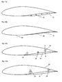
- Fig. 1A shows an example of a profile of a wind turbine blade 2 with chamber different from the chord line (corresponding to the x-axis).
- the blade has a suction side 4 and a pressure side 6 connected in the leading edge 8 and the trailing edge 10.
- the blade further comprises an active elastic member 12 arranged at the pressure side.
- the active elastic member is shown as a broken line (indicated by NACA 62614 I) and corresponds to active elastic member in the expanded state.
- the active elastic member forms part of a compartment 14 for receiving a fluid, such as air.
- Fig. 1B a part of Fig. 1A corresponding to 0.6 to 0.9 of the chord is shown. It is particularly observed that the thickness at the elastic member increases upon expansion of the active elastic member. Here, the increase in thickness is in the order of 30-40% at the arrow corresponding to about 0.77 chord length from the leading edge. Experimental results have shown that an increase in thickness in the order of 10 - 150% in at least a part of the range between 0.65 - 0.9 chord length from the leading edge will typically lead to suitable properties of the blade.
- the example profile is a NACA 63615 profile but the same principles may be applied for other wind turbine blades. Particularly, it is preferred that the profile has a high maximum lift coefficient.
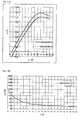
- Fig. 2 also concerns an airfoil of a wind turbine blade according to the present invention.
- Fig. 2A shows the profile with two further profiles indicated as NACA63615 I and NACA63615 HI.
- the two further profiles may be formed by deforming the active elastic member in two steps, by having an active elastic member with two compartments or two individual active elastic members arranged on top of each other in the section shown in Fig. 2A .
- the lift diagram of the three profiles is shown in Fig. 2B . It is observed that the lift coefficient decreases with the size of the deviation of the airfoil from the original, non-deformed airfoil indicated NACA 63615.
- Fig. 2C shows the decrease in lift coefficient for the two adjusted airfoils is shown relative to the lift coefficient of the original, non-deformed airfoil.
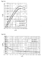
- Fig. 3 also concerns an airfoil for a wind turbine blade according to the present invention.
- Fig. 3A shows the original profile together with a profile with the active elastic member deformed (NACA 63615 I) and a profile with both the active elastic member deformed and the flap 16 bent upwards.
- the trailing region of the blade is shown in further details. It should be observed that for the purpose of modelling, a sharp trailing edge is utilised, whereas the practically applied trailing edge has a finite trailing edge of in the order of about 0.1 to 1% of the chord length.
- the bending of the flap may take place simultaneously with the deformation of the active elastic member, or the bending of the flap may take place in a separate step as indicated here.
- Fig. 3C The lift diagram for the three profiles shown in Fig. 3A is shown in Fig. 3C . It is observed that the bending of the flap towards the suction side considerably boost the decrease of the lift coefficient. This is even more evident in Fig. 3D , where the decrease in the lift coefficient for the profiles relative to the original, non-deformed airfoil is shown. Here, it is observed that the decrease in lift for the airfoil with the flap bent towards the suction side is in the order of 30% or more below the critical angle of attack.
- the blade cross sections shown in Fig. 4 indicate how linear actuators 22 may be utilised to actuate the deformation of the active elastic member 12.
- the active elastic member 12 is shown in the deformed shape.
- the principle sketch in Fig. 4A has four linear actuators in the plane of the cross section, but either more or fewer actuators may be used dependent on the size of the actual blade, so that typically the larger the blade, the more the actuators. Furthermore, the required number of actuators also depends on the flexibility of the active elastic member.
- Fig. 4B the same blade cross section is shown, with the active elastic member in the non-deformed state and the actuators in a compressed state.
- the actuators are shown as positioned on top of the rigid blade wall 20, but in many cases, the actuators may preferably be integrated with or submersed into the blade wall.
- FIG. 5 A cross section of a wind turbine blade with an active elastic member adapted for deformation by entering/retrieving fluid into the compartment 14 is shown in Fig. 5 .
- the blade also comprises a fluid distribution system 24.
- the system is basically formed by two tubes 24 arranged substantially orthogonal to the plane of the cross section.
- the tubes are in communication with the compartment 14 via connection fittings (not numbered).
- the tubes may e.g. be one tube for distributing the fluid to the compartment (preferably the tube towards the leading edge) and one tube for returning the fluid from the compartment to a unit for distributing the fluid, such as a pump (not shown).
- the tubes may be connected to further compartments arranged in other cross sections of the blade.
- a sensor 26 such as a pressure gauge, is arranged in communication with the compartment, so that the presence/absence of fluid and/or the pressure of the fluid may be established during use.
- the system described in Fig. 5A may for example be used for a circulated gas, such as air or nitrogen, or for a circulated liquid, such as water or another hydraulic fluid.
- Fig. 5B illustrates a cross section of another embodiment of the wind turbine according to the invention.
- only one distribution system or tube 24 is present. This embodiment may be particularly suitable in two distinct situations.
- the active elastic member may be utilised when the active elastic member is operated by pressure so that during use the compartment is expanded by air or another gas entering from the fluid distribution system 24 via the receive valve 24 and into the compartment 14.
- the compartment is contracted by closing the receive valve connecting the distribution system 24 to the compartment and opening the release valve 28 so that the active elastic member will return to a relaxed state where the compartment is contracted by releasing the compressed air from the compartment. This requires that the equilibrium state of the active elastic member corresponds to the compartment being expanded.
- the blade with the cross section illustrated in Fig. 5B may be operated by vacuum, so that during use, the compartment is expanded by air entering from the surface of the blade wall 20 via the receive valve;28.
- the valve 28 has changed purpose from release mode in the above case to receive mode in the present case.
- the relaxed state of the compartment 14 should be for the compartment to be expanded (as shown in Fig. 5B ). This is particularly advantageous from a safety point of view, as the relaxed state provides an airfoil with a lower maximum lift coefficient and hence will tend to lower the response of the wind in the unlikely case of failure.
- the receive valve 28 should be closed and the valve connecting the compartment 14 to the distribution system should be opened.
- the distribution system should be connected to a vacuum system, such as a vacuum pump to extract the air from the compartment.
- Fig. 6 is a section along the length of the blade of Fig. 5 in the plane indicated by the dashed line A---A.
- the tube of the distribution system 24 is therefore preferably the return tube.
- the connection to the compartments 14 of the active elastic member 12 is arranged near the end of the compartment 14 towards the tip of the blade.
- a valve 28 is arranged in the connection between the compartment 14 and the distribution system.
- the valve may e.g. be a magnetic valve or another valve operable by a control unit (not shown).
- the advantage of the arrangement of the connection between the compartment and the distribution system is mainly based on the fluid being forced towards the tip end of the compartment by the centrifugal force during use. This will help emptying of the compartment during use.
- a piece of a wind turbine blade 2 is shown.
- the section of the blade which is seen in Fig. 7 , comprises two active elastic members 12.
- the active elastic members are connected in the longitudinal direction of the blade.
- the connection 30 between the adjacent active elastic members is preferably prepared so that no abrupt changes in the shape of the blade are present in any configuration of the active elastic members.
- no abrupt change is here also meant changes in the longitudinal direction of the blade and not only transverse to the length of the blade. This reduces the likelihood of the airflow over the surface of the blade separating prematurely, i.e. away from the trailing edge.
- active elastic member(s) and/or flap(s) are arranged on the outermost part of the blade, such as the outermost 2/3 of the length of the blade or - more preferably - the outermost 1/2 of the blade, as the outer part of the blade is accounting for the majority of the power output.
- the outermost parts of the blade tend also to cause a majority of the fatigue wear, which may be reduced considerably by the wind turbine blades and the method according to the present invention.
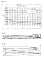
- Fig. 8 relates to a preferred overall principle of operating a wind turbine blade according to the invention.
- Fig. 8 indicates the desired response to a change in the speed of the incoming wind. This may either be the local incoming wind at the very active elastic member at the instant of operation, or an overall wind averaged over time or over position along the length of the blade.
- the x-axis indicates the speed of the incoming wind.
- Two threshold wind speed levels are indicated 1 and 2. Starting from the left hand side, the first half of the plot indicated how to react to a decrease in the speed of the incoming wind.
- the active elastic member should be configured in the second shape, i.e. with a relatively low maximum lift coefficient, c L.max 2 .
- the delayed switching allows for a safety margin.
- the safety margin may be limited according to the speed of the change of configuration and the rate of establishing the incoming wind speed, so that the faster the switching of configuration and the faster the rate of establishing the speed of the incoming wind, the narrower the safety margin should be utilised.
- the safety margin ensures that the active elastic member does not flip/flap forward and back without this being necessary. This method of operation is particularly suitable for establishing an optimum configuration based on mean incoming wind. It may be utilised for a wind turbine blade with just one active elastic member, but by overlapping several similar control patterns, typically one for each active elastic member or for each group of active elastic members, a fine control may easily be realised.
- Fig. 9A shows a sketch of a wind turbine blade with three active elastic members E ⁇ , E ⁇ and E ⁇ and three flaps F I , F II and F III .
- the flaps are arranged at a corresponding active elastic member.
- the flaps and active elastic members may e.g. be operated by artificial intelligence, such as fussy logic, or another self-learning expert system.
- a set of rules may be provided for the regulation of each of the flaps and active elastic members.
- Fig. 9B an example of a set of rules is indicated.
- the speed of the incoming wind at each of the active elastic members is indicated.
- the variation in the speed of the incoming wind is much greater for the tip part of the blade than for parts of the blade further towards the blade root.
- the poorer conventional cyclic pitch will be at providing an optimised power output, as pitching of the full blade cannot take into account the radial differences in the variation of the speed of the incoming wind.
- the cyclic pitch may be considerably optimised by overlaying the cyclic pitch with a variation of the airfoil shape as a function of the longitudinal position along the length of the blade. This may e.g. be realised with the wind turbine blade according to the present invention.
- FIG. 9B an example of the regulation scheme described in Fig. 8 is shown for the active elastic members.
- First and second threshold values, T1 and T2 for each of the active elastic members, E ⁇ , E ⁇ and E ⁇ are indicated by longitudinal lines.
- the active elastic member E ⁇ is not shifted from the first shape at all, whereas during the movement of the blade towards the top position, the tip active elastic member, E ⁇ , is shifted from the first shape to the second shape before the middle active elastic member, E ⁇ .
- the effective aerodynamic rotor diameter is virtually reduced.
- the variation in elasticity and merely the length of the blade lead to the tip being slightly out of phase when pitching the blade. This is for example a problem when the blade is operated with cyclic pitch. If the aerodynamic properties of the blade are mainly adjusted by active elastic members and/or flaps according to the present invention, or the operation of active elastic members is combined with pitching, then the delay due to elasticity of the blade may be circumvented and a much more optimum operation may therefore be realised.
- Wind turbine blade 4 Suction side 6 Pressure side 8 Leading edge 10 Trailing edge 12 Active elastic member 14 Compartment 16 Flap 20 Wind turbine blade wall 22 Actuator means 24 Fluid distribution system 26 Pressure gauge 28 Valve 30 Connection between adjacent active elastic members
Claims (29)
- Une pale d'aérogénérateur (2) ayant un côté d'aspiration (4) et un côté de pression (6), lesquels côtés sont reliés à un bord d'attaque (8) et à un bord de fuite (10), la pale comprenant en outre un élément élastique actif (12) disposé avec accès à la surface de la pale d'aérogénérateur (2), dans laquelle l'élément élastique actif (12) est déformable depuis une première forme vers une deuxième forme et le coefficient de portance maximum, cL, max. 1, d'un profil aérodynamique avec l'élément élastique actif dans la première forme est plus grand que le coefficient de portance maximum, cL, max. 2, du profil aérodynamique avec l'élément élastique actif (12) dans la deuxième forme, dans laquelle ledit élément élastique actif (12) est disposé de sorte que l'épaisseur de la pale change à la déformation de l'élément élastique actif d'une telle manière que la ligne de courbure est décalée par rapport à la corde de référence, caractérisée en ce que ledit élément élastique actif (12) est disposé sur le côté de pression (6) du profil aérodynamique de la pale (2).
- Pale d'aérogénérateur (2) selon la revendication 1 dans laquelle l'élément élastique actif (12) est disposé dans une zone située entre le bord de fuite (10) et environ 40% de la longueur de la corde depuis le bord d'attaque, de préférence l'élément élastique actif est disposé dans une zone située entre le bord de fuite et environ 50% de la longueur de la corde depuis le bord d'attaque et/ou dans laquelle l'élément élastique actif pour le profil aérodynamique est disposé à environ 50-70% de la corde, de préférence à environ 55 - 65% de la corde, tel qu'à environ 60% de la corde et à environ 80 - 90% de la corde, de préférence à environ 90 - 98% de la corde , tel qu'à environ 95% de la corde et/ou dans laquelle l'élément élastique actif est disposé dans les 50% extérieurs du rayon de la pale, de préférence l'élément élastique actif est disposé dans les 25% extérieurs du rayon.
- Pale d'aérogénérateur selon une quelconque des revendications 1 ou 2 dans laquelle ledit élément élastique actif est disposé dans une zone située entre l'épaisseur maximum du profil aérodynamique de la pale et le bord de fuite, et/ou comprenant en outre un anémomètre disposé près du bout de la pale, ledit anémomètre étant relié du point de vue fonctionnel à une unité de commande capable de contrôler la forme de l'élément élastique actif, de préférence l'anémomètre étant un anémomètre à laser ou un tube de pitot, et/ou comprenant en outre un moyen de tension de la pale disposé dans la pale pour établir la tension de la pale, ledit moyen de tension de pale étant relié du point de vue fonctionnel à une unité de commande capable de contrôler la forme de l'élément élastique actif, de préférence le moyen de tension de la pale étant un extensomètre disposé dans une paroi de la pale ou un longeron de la pale ou un moyen comprenant une fibre optique ou conductrice.
- Pale d'aérogénérateur selon une quelconque des revendications 1 à 3 comprenant une pluralité d'éléments élastique actifs disposés sur le côté de pression de la pale, de préférence 2, 3, 4, 5, 6, 7, 8, 9, 10 ou plus d'éléments élastiques actifs, d'une façon plus préférée une majorité d'éléments élastiques actifs sont disposés dans une zone située entre l'épaisseur maximum des profils aérodynamiques de la pale et le bord de fuite, et/ou comprenant un nombre d'anémomètres répartis longitudinalement le long de la pale, dans laquelle chacun desdits anémomètres est disposé près d'un différent de ladite pluralité d'éléments élastiques actifs et ledit nombre d'anémomètres étant relié du point de vue fonctionnel à une unité de commande capable de contrôler la forme de ladite pluralité d'éléments élastiques actifs individuellement, de préférence l'anémomètre étant un anémomètre à laser ou un tube de pitot et/ou dans laquelle au moins un de la pluralité des éléments élastiques actifs s'étend de 2 à 30 mètres dans la longueur de la pale, de préférence 5 à 20 mètres, d'une façon plus préférée au moins deux de la pluralité des éléments élastiques actifs s'étendent de 8 à 15 mètres dans la longueur de la pale, et/ou dans laquelle au moins un de la pluralité des éléments élastiques actifs s'étend de 3% à 50% de la longueur de la pale d'aérogénérateur, de préférence de 5% à 40% de la longueur de la pale d'aérogénérateur, d'une façon plus préférée au moins deux de la pluralité des éléments élastiques actifs s'étendent sur 10% à 25% de la longueur de la pale d'aérogénérateur, et/ou dans laquelle au moins deux de la pluralité des éléments élastiques actifs sont disposés essentiellement bout à bout de sorte qu'un premier élément élastique actif s'étend d'un deuxième élément élastique actif dans la longueur de la pale, et/ou dans laquelle au moins deux de la pluralité des éléments élastiques actifs sont disposés côte à côte de sorte qu'un premier élément élastique actif s'étend depuis le deuxième élément élastique actif essentielllement orthogonal sur la longueur de la pale, et/ou dans laquelle au moins deux de la pluralité des éléments élastiques actifs sont disposés au moins se chevauchant partiellement dans la longueur de la pale et/ou comprenant en outre un moyen pour contrôler individuellement la forme des éléments élastiques actifs.
- Pale d'aérogénérateur selon une quelconque des revendications 1 à 4 dans laquelle la deuxième forme de l'élément élastique actif est un état détendu de l'élément élastique actif, et/ou dans laquelle le coefficient de portance maximum, cL, max.1, du profil aérodynamique avec l'élément élastique actif dans la première forme est au moins de 10% plus grand que le coefficient de portance maximum, cL, max. 2, du profil aérodynamique avec l'élément élastique actif dans la deuxième forme, de préférence le coefficient de portance maximum, cL, max. 1, du profil aérodynamique avec l'élément élastique actif dans la première forme est au moins de 15% plus grand que le coefficient de portance maximum, cL, max. 2 du profil aérodynamique avec l'élément élastique actif dans la deuxième forme, de façon plus préférée le coefficient de portance maximum, cL, max. 1, du profil aérodynamique avec l'élément élastique actif dans la première forme est au moins de 20% plus grand que le coefficient de portance maximum, cL, max. 2, du profil aérodynamique avec l'élément éalstique actif dans la deuxième forme.
- Pale d'aérogénérateur selon une quelconque des revendications 1 à 5 dans laquelle la différence du coefficient de portance pour le profil aérodynamique avec l'élément élastique actif entre la première forme et la deuxième forme, ΔcL, doit être plus grande que 10% du plus grand des coefficients de portance à un angle d'attaque de tous les angles d'attaque entre α = αmax - 5° à αmax, de préférence ΔcL > 20% du plus grand des coefficients de portance à l'angle d'attaque pour tous les angles d'attaque entre α = αmax - 5° à αmax, tel que ΔcL > 25% ou même ΔcL > 50%, de façon plus préférée la gamme de α, pour laquelle ΔcL doit être au-dessus de la valeur définie, est α = 0° à αmax + 2° et même d'une façon encore plus préférée la gamme de α pour laquelle ΔcL doit être au-dessus de la valeur définie, est α = -2 ° à αmax + 3 ° , où αmax représente l'angle d'attaque correspondant au coefficient de portance maximum, et/ou dans laquelle le coefficient de portance maximum du profil aérodynamique avec l'élément élastique actif dans la première forme, cL, max. 1, est plus grand que 1,2 et/ou le coefficient de portance maximum du profil aérodynamique avec l'élément élastique actif dans la deuxième forme, cL, max. 2, est inférieur à 1,0, où le coefficient de portance maximum correspond au Re dans la gamme de 1 - 10 millions et à un écoulement bidimensionnel passant sur une surface de profil lisse, de préférence cL, max. 1, est plus grand que 1,25 et/ou cL, max. 2, est inférieur à 0,9, où les coefficients de portance maxima correspondent au Re dans la gamme de 1 - 10 millions et à un écoulement bidimensionel passant sur une surface de profil lisse, et/ou dans laquelle la courbure du prodil aérodynamique avec l'élément élastique actif dans la première forme diffère de la courbure du profil aérodynamique avec l'élément élastique actif dans la deuxième forme et la différence de courbure est une distance d'au moins 0,25% de corde orthogonale à la corde de référence de profil pour une partie du profil aérodynamique correspondant à au moins 10% de la corde de référence, de préférence la différence de courbure est une distance d'au moins 0,25% de corde orthogonale à la corde de référence pour une partie du profil aérodynamique correspondant à au moins 15% de la corde de référence, d'une façon plus préférée, la différence de courbure est une distance d'au moins 0,30% de corde orthogonale à la corde de référence pour une partie du profil aérodynamique correspondant à au moins 10% de la corde de référence et de façon la plus préférée, la différence de courbure est une distance d'au moins 0,30% de corde orthogonale à la corde de référence pour une partie du prodil aérodynamique correspondant à au moins 15% de la corde de référence, et/ou dans laquelle la ligne de courbure du prodil aérodynamique avec l'élément élastique actif dans la première forme s'écarte d'au moins 1,5% de la longueur de corde orthogonalement de la corde de référence du profil aérodynamique avec l'élément élastique actif dans la première forme dans au moins 10% de la gamme entre le bord d'attaque et le bord de fuite, de préférence dans au moins 20% de la gamme entre le bord d'attaque et le bord de fuite, tel que dans au moins 30% de la gamme entre le bord d'attaque et le bord de fuite, de façon plus préférée, la ligne de courbure du prodil aérodynamique avec l'élément élastique actif dans la première forme s'écarte d'au moins 3% de la longueur de corde orthogonalement de la corde de référence du prodil aérodynamique avec l'élément élastique actif dans la première forme dans au moins 10% de la gamme entre le bord d'attaque et le bord de fuite, de préférence dans au moins 20% de la gamme entre le bord d'attaque et le bord de fuite, tel que dans au moins 30% de la gamme entre le bord d'attaque et le bord de fuite.
- Pale d'aérogénérateur selon une quelconque des revendications 1 à 6 dans laquelle l'élément élastique actif comprend un compartiment destiné à recevoir un fluide, et/ou dans laquelle l'élément élastique actif en combinaison avec une partie rigide de la pale d'aérogénérateur forme un compartiment destiné à recevoir un fluide, et/ou comprenant en outre une vanne réceptrice pour réguler le transport du fluide vers ledit compartiment, ladite vanne réceptrice étant disposée près du compartiment à contrôler et ladite vanne réceptrice étant fonctionnellement reliée audit compartiment, et/ou dans laquelle la vanne réceptrice est disposée près d'une extrémité du compartiment vers le pied de pale, et/ou comprenant une soupape de décharge pour réguler le transport du fluide depuis ledit compartiment, ladite soupape de décharge étant disposée près du compartiment à contrôler et ladite soupape de décharge étant fonctionnellement reliée audit compartiment, et/ou dans laquelle la soupape de décharge est disposée près d'une extrémité du compartiment vers le bout de la pale, et/ou dans laquelle la soupape de décharge est montée pour libérer le fluide vers une surface de la pale d'aérogénérateur.
- Pale d'aérogénérateur selon une quelconque des revendications 1 à 6 comprenant en outre un moyen de détection, comme un manomètre ou un débitmètre, le moyen de détection étant fonctionnellement relié au compartiment et ledit moyen de détection étant capable d'établir un volume de fluide dans la compartiment, par ex.: via la pression du fluide dans le compartiment ou le débit du fluide et/ou depuis le compartiment, et/ou comprenant en outre un système de distribution de fluide en communication avec le compartiment, de préférence via ladite vanne réceptrice et/ou ladite soupape de décharge, et/ou comprenant en outre un moyen destiné au transport du fluide, ledit moyen étant en communication avec le système de distribution du fluide.
- Pale d'aérogénérateur selon la revendications 8 dans laquelle le fluide est un gaz.
- Pale d'aérogénérateur selon une quelconque des revendications 1 à 9 comprenant en outre un volet disposé près du bord de fuite du profil aérodynamique, ledit volet étant actif dans le sens qu'il peut être actionné par un moyen actionneur entre une première position et une deuxième position, le coefficient de portance maximum du profil aérodynamique avec le volet dans la première position est plus grand que le coefficient de portance maximum du pofil aérodynamique avec le volet dans la deuxième position.
- Pale d'aérogénérateur selon la revendication 10, dans laquelle le volet s'étend de entre 80 à 90% de la longueur de corde du bord d'attaque au bord de fuite, de préférence le volet s'étend entre environ 85% de la longueur de corde du bord d'attaque au bord de fuite, et/ou dans laquelle la deuxième position du volet est vers le côté d'aspiration du profil aérodynamique comparée à la première position du volet et la deuxième position du volet est un état détendu du volet.
- Pale d'aérogénérateur selon une quelconque des revendications 10 ou 11 comprenant une pluralité de volets disposés près du bord de fuite de la pale, de préférence 2, 3, 4, 5, 6, 7, 8, 9, 10 volets ou plus disposés près du bord de fuite, et/ou dans laquelle au moins un de la pluralité des volets s'étend de 2 à 20 mètres dans la longueur de la pale, de préférence de 5 à 15 mètres, de façon plus préférée, au moins deux de la pluralité des éléments élastiques actifs s'étendent de 5 à 15 mètres dans la longueur de la pale, et/ou dans laquelle au moins un de la pluralité des volets s'étend sur 3% à 50% de la longueur de la pale d'aérogénérateur, de préférence sur 5% à 40% de la longueur de la pale d'aérogénérateur, d'une façon plus préférée au moins deux de la pluralité des volets s'étendent sur 10% à 25% de la longueur de la pale d'aérogénérateur, et/ou dans laquelle la pluralité des volets est disposée l'un étendant l'autre dans le sens de la longueur de la pale et un raccord élastique est disposé entre les volets adjacents de sorte que les volets forment une surface continue libre de gradins dans le sens longitudinal de la pale, et/ou dans laquelle le moyen actionneur peut être actionné par un fluide, de préférence par le même fluide que les éléments élastiques actifs, et/ou dans laquelle le moyen actionneur est fonctionnellement relié à un système de distribution de fluide, lequel système de distribution de fluide est en communication avec l'élément élastique actif.
- Sous-unité pour l'installation d'une pale d'aérogénérateur, laquelle pale d'aérogénérateur possède un coté d'aspiration et un côté de pression, lesquels côtés sont reliés à un bord d'attaque et un bord de fuite pour former une surface de pale rigide, ladite sous-unité comprenant un élément élastique actif adapté eu égard à la forme et à la taille à raccorder à une partie de surface rigide d'une pale d'aérogénérateur, de sorte que pendant le fonctionnement d'un aérogénérateur comprenant ladite pale d'aérogénérateur avec ladite sous-unité, ledit élément élastique actif est déformable d'une première forme à une deuxième forme de sorte que l'épaisseur de la pale change à la déformation de l'élément élastique actif de telle manière que la ligne de courbure est décalée par rapport à la corde de référence de la pale,et, le coefficient de portance maximum de la structure combinée de la sous-unité et de la pale d'aérogénérateur dans la première forme, cL, max. 1, est plus grand que le coefficient de portance maximum de la structure combinée de la sous-unité et de la pale d'aérogénérateur avec l'élément élastique actif dans la deuxième forme, cL, max. 2.
- Mode de fonctionnement d'un aérogénérateur possédant une pale d'aérogénérateur selon une quelconque des revendications 1 à 12, comprenant les étapes d'établissement de la vitesse du vent arrivant, de préférence via un anémomètre disposé sur la pale d'aérogénérateur et si la vitesse du vent arrivant est inférieure à une première valeur de seuil, telle que 10m/s, pour déformer alors un élément élastique actif de la deuxième forme à la première forme de sorte que la portance du profil aérodynamique sur l'élément élastique actif est augmentée.
- Mode de fonctionnement selon la revendication 14, comprenant en outre l'étape, si la vitesse du vent arrivant est inférieure à une deuxième valeur de seuil, d'actionner le volet de la deuxième position à la première position de sorte que la portance du profil aérodynamique au volet est augmentée, de préférence la deuxième valeur de seuil est supérieure à la première valeur de seuil telle que 15 m/s.
- Mode de fonctionnement d'un aérogénérateur possédant une pale d'aérogénérateur selon une quelconque des revendications 1 à 12, comprenant les étapes d'établissement de la tension de la pale d'aérogénérateuyr, de préférence via un moyen de tension de pale disposé dans la pale d'aérogénérateur et si la tension est inférieure à une première valeur de seuil, pour déformer alors l'élément élastique actif de la deuxième forme à la première forme de sorte que la portance du profil aérodynamique à l'élément élastique actif est augmentée.
- Mode de fonctionnement d'un aérogénérateur possédant une pale d'aérogénérateur selon une quelconque des revendications 1 à 12, comprenant les étapes d'établissement du taux de changement de la tension de la pale d'aérogénérateur, de préférence par un moyen de tension de pale disposé dans la pale d'aérogénérateur et si la tension augmente plus rapidement qu'une première valeur de seuil, pour déformer l'élément élastique actif de la première forme à la deuxième forme de sorte qe la portance du profil aérodynamique à l'élément élastique actif est augmentée, et/ou comprenant en outre l'étape, si la vitesse du vent de tension est inférieure à une deuxième valeur de sueil, d'actionner le volet de la deuxième position à la première position de sorte que la portance du poprfil aérodynamique au volet est augmentée.
- Mode selon une quelconque des revendications 14 à 17 dans lequel l'aérogénérateur est à pas régulé et comprenant en outre l'étape de réglage de l'angle de pas général des pales selon la vitesse et/ou la tension du vent établie.
- Mode selon une quelconque des revendications 14 à 18 dans lequel la pale d'aérogénérateur comprend au moins deux éléments élastiques actifs disposés à des distances différentes du pied de pale et au moins deux des éléments élastiques actifs sont indépendamment déformables, ledit mode comprenant les étapes pour chaque élément élastique actif d'établir la vitesse du vent arrivant audit élément élastique actif et si la vitesse du vent arrivant est inférieure à une valeur de seuil locale pour cette élément élastique actif, telle que 10 m/s, pour déformer alors ledit élément élastique actif de la deuxième forme à la première forme de sorte que la portance du profil aérodynamique audit élément élastique actif est augmentée.
- Mode selon une quelconque des revendications 14 à 19 dans lequel des paramètres, tels que les valeurs de seuil, pour la régulation du fonctionnement de l'aérogénérateur sont optimisés de sorte que pendant le fonctionnement, l'aérogénérateur fournira une production d'énergie dans un niveau acceptable d'usure de l'aérogénérateur, et/ou dans lequel des paramètres, tels que des valeurs de seuil pour la régulation du fonctionnement de l'aérogénérateur sont optimisés de sorte que pendant le fonctionnement de l'aérogénérateur fournira une production d'énergie dans un niveau acceptable d'émissions sonores de l'aérogénérateur.
- Mode selon une quelconque des revendications 14 à 20 dans lequel l'ajustement de la forme des éléments élastiques actifs individuels est répété avec une fréquence inférieure à environ 0,1 Hz, de préférence l'ajustement de la forme des éléments élastiques actifs individuels est répété avec une fréquence inférieure à environ 0,01 Hz, et/ou dans lequel l'ajustement de la forme des éléments élastiques actifs individuels est répété avec une fréquence supérieure à 10 Hz, de préférence avec une fréquence de plus de 20 Hz et de façon plus préférée avec une fréquence de plus de 40 Hz, et/ou dans lequel l'ajustement de la forme des éléments élastiques actifs individuels est répété avec une fréquence correspondant à moins d'un 8ème d'une rotation de la pale autour de l'axe de rotation et de façon plus préférée avec une fréquence correspondant à moins d'un 40ème d'une rotation de la pale autour de l'axe de rotation.
- Mode selon la revendication 14 ou 21 dans lequel la régulation est cyclique de sorte que la période de régulation correspond à une rotation du rotor d'aérogénérateur.
- Mode selon une quelconque des revendications 14 à 22 comprenant en outre l'étape de régler le pas individuel de la pale, en cyclique.
- Mode selon une quelconque des revendications 14 à 23 dans lequel la forme sur au moins un élément élastique actif ou volet est ajustée progressivement de sorte que l'élément élastique actif est, soit dans la première forme, soit dans la deuxième forme.
- Mode selon une quelconque des revendications 14 à 23 dans lequel la forme sur au moins un élément élastique actif ou volet est ajustée essentiellement en continu de sorte que l'élément élastique actif peut être déformé en plusieurs étapes, telles que 3, 4, 5, 6, 7, 8 étapes ou en continu sans étape entre la forme fournissant le plus petit coefficient de portance maximum et la forme fournissant le plus grand coefficient de portance maximum.
- Mode de fonctionnement d'un aérogénérateur possédant une pale d'aérogénérateur selon une quelconque des revendications 1 à 12, ladite pale d'aérogénérateur comprenant une pluralité d'éléments élastiques actifs et/ou une pluralité de volets, le mode comprenant les étapes d'établissement d'au moins une vitesse de vent arrivant, des émissions sonores, de la contrainte de pale, l'établissement d'une configuration souhaitée d'une pluralité d'élément(s) élastique(s) actif(s) et/ou de volet(s) de la pale basé sur l'intelligence artificielle et l'ajustement de(s) (l')élément(s) élastique(s) actif(s) et du/des volet(s) en conséquence, de préférence les étapes du mode de fonctionnement sont répétées à une fréquence correspondant à au moins 8 fois une fréquence de rotation de la pale d'aérogénérateur.
- Utilisation d'une pale d'aérogénérateur selon une quelconque des revendications 4 à 12 pour un aérogénérateur pouvant fonctionner par variation individuelle dépendant du rayon de la section du profil aérodynamique.
- Un aérogénérateur comprenant au moins une pale d'aérogénérateur selon une quelconque des revendications 1 à 12.
- Aérogénérateur selon la revendication 28 comprenant en outre un anémomètre disposé sur un moyeu d'aérogénérateur, ledit anémomètre étant fonctionnellement relié à une unité de commande capable de contrôler la forme d'un élément élastique actif de ladite au moins une pale d'aérogénérateur, de préférence l'anémomètre étant un anémomètre à laser disposé à un angle non horizontal et étant capable de mesurer la vitesse du vent arrivant à des distances différentes de l'anémomètre à laser de sorte que la vitese du vent peut être établie pendant l'utilisation dans une pluralité de niveaux verticaux en face de la(des) pale(s) d'aérogénérateur.
Applications Claiming Priority (1)
| Application Number | Priority Date | Filing Date | Title |
|---|---|---|---|
| PCT/IB2005/053397 WO2007045940A1 (fr) | 2005-10-17 | 2005-10-17 | Pale d’aérogénérateur à profil aérodynamique variable |
Publications (2)
| Publication Number | Publication Date |
|---|---|
| EP1952015A1 EP1952015A1 (fr) | 2008-08-06 |
| EP1952015B1 true EP1952015B1 (fr) | 2013-05-15 |
Family
ID=35929971
Family Applications (1)
| Application Number | Title | Priority Date | Filing Date |
|---|---|---|---|
| EP05792070.4A Not-in-force EP1952015B1 (fr) | 2005-10-17 | 2005-10-17 | Pale d aérogénérateur à profil aérodynamique variable |
Country Status (7)
| Country | Link |
|---|---|
| US (1) | US8157533B2 (fr) |
| EP (1) | EP1952015B1 (fr) |
| CN (1) | CN101351640B (fr) |
| CA (1) | CA2625070A1 (fr) |
| DK (1) | DK1952015T3 (fr) |
| ES (1) | ES2418368T3 (fr) |
| WO (1) | WO2007045940A1 (fr) |
Cited By (1)
| Publication number | Priority date | Publication date | Assignee | Title |
|---|---|---|---|---|
| WO2019038313A1 (fr) | 2017-08-23 | 2019-02-28 | Lm Wind Power International Technology Ii Aps | Pale d'éolienne et procédé d'opérabilité d'une pale d'éolienne |
Families Citing this family (84)
| Publication number | Priority date | Publication date | Assignee | Title |
|---|---|---|---|---|
| BRPI0621442A2 (pt) * | 2006-03-16 | 2011-12-13 | Vestas Wind Sys As | método para reduzir fadiga por efeito de cargas nos componentes de uma turbina eólica submetida a esforço assimétrico de carga de seu rotor, sistema de controle para reduzir as fadiga por efeito de cargas nos componentes de uma turbina eólica submetidos a esforço assimétrico de carga no plano de seu rotor, turbina eólica, e área de captação de ventos |
| CN101454564B (zh) * | 2006-04-02 | 2014-04-23 | 考特能源有限公司 | 具有细长叶片的风力涡轮机 |
| EP2044324A1 (fr) * | 2006-07-07 | 2009-04-08 | Danmarks Tekniske Universitet | Geometrie a section de bord de fuite variable pour pale d'eolienne |
| ES2553168T5 (es) * | 2007-03-30 | 2018-12-10 | Vestas Wind Systems A/S | Turbina eólica con control de paso |
| WO2008131800A1 (fr) | 2007-04-30 | 2008-11-06 | Vestas Wind Systems A/S | Pale d'éolienne |
| US9039372B2 (en) | 2007-04-30 | 2015-05-26 | Vestas Wind Systems A/S | Wind turbine blade |
| ES2609426T3 (es) * | 2007-05-25 | 2017-04-20 | Siemens Aktiengesellschaft | Sistema de accionamiento para una aleta de pala de turbina eólica |
| ES2324002B1 (es) * | 2007-06-22 | 2010-05-13 | GAMESA INNOVATION & TECHNOLOGY, S.L. | Pala de aerogenerador con alerones deflectables. |
| EP2017468A1 (fr) * | 2007-07-20 | 2009-01-21 | Siemens Aktiengesellschaft | Procédé pour le contrôle de lacet d'éolienne |
| ES2326352B1 (es) * | 2007-09-14 | 2010-07-15 | GAMESA INNOVATION & TECHNOLOGY, S.L. | Pala de aerogenerador con alerones deflectables controlados por cambios de la presion en la superficie. |
| EP2053240B1 (fr) * | 2007-10-22 | 2011-03-30 | Actiflow B.V. | Éolienne avec contrôle de couche limite |
| US8418967B2 (en) | 2008-02-21 | 2013-04-16 | Cornerstone Research Group, Inc. | Passive adaptive structures |
| EP2250084A4 (fr) | 2008-02-21 | 2011-03-09 | Cornerstone Res Group Inc | Structures adaptatives passives |
| ES2343397B1 (es) * | 2008-03-07 | 2011-06-13 | GAMESA INNOVATION & TECHNOLOGY, S.L. | Una pala de aerogenerador. |
| US8192161B2 (en) * | 2008-05-16 | 2012-06-05 | Frontier Wind, Llc. | Wind turbine with deployable air deflectors |
| US8267654B2 (en) | 2008-05-16 | 2012-09-18 | Frontier Wind, Llc | Wind turbine with gust compensating air deflector |
| US20110229320A1 (en) * | 2008-08-29 | 2011-09-22 | Vestas Wind Systems A/S | Wind turbine blade with device for modifying the blade aerodynamic surface |
| CN101457736A (zh) * | 2008-09-05 | 2009-06-17 | 张云龙 | 一种风力发动机的复合转子系统 |
| KR20110063541A (ko) * | 2008-09-19 | 2011-06-10 | 코트에너지 비브이 | 낮은 유도 팁을 사용한 윈드 터빈 |
| US8057174B2 (en) * | 2008-10-09 | 2011-11-15 | General Electric Company | Method for controlling a wind turbine using a wind flow model |
| EP2350452B2 (fr) | 2008-10-14 | 2020-08-19 | Vestas Wind Systems A/S | Pale d'éolienne avec dispositif pour modifier la surface ou la forme aérodynamique |
| EP2347125A2 (fr) * | 2008-10-14 | 2011-07-27 | Vestas Wind Systems A/S | Pale d'éolienne |
| NL2002476C2 (en) * | 2009-02-02 | 2010-08-03 | Univ Delft Tech | WIND TURBINE. |
| DE102009015679A1 (de) * | 2009-03-31 | 2010-10-07 | Robert Bosch Gmbh | Stationäre Energiegewinnungsanlage mit Steuereinrichtung und Verfahren zur Steuerung der Energiegewinnungsanalge |
| GB2469854A (en) * | 2009-04-30 | 2010-11-03 | Vestas Wind Sys As | Wind turbine rotor blade |
| US7945350B2 (en) * | 2009-07-07 | 2011-05-17 | General Electric Company | Wind turbine acoustic emission control system and method |
| WO2011026495A2 (fr) * | 2009-09-04 | 2011-03-10 | Vestas Wind Systems A/S | Pale de rotor d'éolienne |
| EP2302208A1 (fr) * | 2009-09-23 | 2011-03-30 | Siemens Aktiengesellschaft | Adaptation dynamique du point de réglage de la durée de fatigue d'un composant structurel d'une machine de génération d'énergie |
| US9039366B2 (en) | 2009-11-11 | 2015-05-26 | Vestas Wind Systems A/S | Control of wind turbine blade lift regulating means |
| EP2327876A1 (fr) | 2009-11-30 | 2011-06-01 | Lm Glasfiber A/S | Pale d'éolienne dotée d'un système optique de mesure de la vitesse du vent |
| WO2011077424A1 (fr) | 2009-12-21 | 2011-06-30 | Ramot At Tel-Aviv University Ltd. | Générateur de tourbillon oscillatoire et ses applications |
| GB2476316B (en) | 2009-12-21 | 2014-07-16 | Vestas Wind Sys As | A wind turbine having a control method and controller for predictive control of a wind turbine generator |
| CN101708773B (zh) * | 2009-12-23 | 2011-09-14 | 西北工业大学 | 气囊式襟翼 |
| GB2476506A (en) | 2009-12-23 | 2011-06-29 | Vestas Wind Sys As | Method And Apparatus Protecting Wind Turbines From Low Cycle Fatigue Damage |
| GB2476507A (en) | 2009-12-23 | 2011-06-29 | Vestas Wind Sys As | Method And Apparatus For Protecting Wind Turbines From Gust Damage |
| US20110164975A1 (en) * | 2010-01-04 | 2011-07-07 | General Electric Company | Wind turbine rotor blades including controllable depressions |
| GB2481461A (en) * | 2010-06-21 | 2011-12-28 | Vestas Wind Sys As | Control of a downstream wind turbine in a wind park by sensing the wake turbulence of an upstream turbine |
| DK2405129T3 (en) * | 2010-07-06 | 2017-03-13 | Lm Wp Patent Holding As | Wind turbine blade with variable rear edge |
| GB2477594B (en) * | 2010-11-25 | 2011-12-28 | Moog Insensys Ltd | Wind turbine rotor blades |
| US8915709B2 (en) | 2010-12-30 | 2014-12-23 | Vestas Wind Systems A/S | Optical angle of attack detector based on light detection and ranging (LIDAR) for control of an aerodynamic surface |
| ITRM20110010A1 (it) * | 2011-01-13 | 2012-07-14 | Francesco Marano | Pala eolica a massa variabile |
| WO2012095478A1 (fr) * | 2011-01-14 | 2012-07-19 | Lm Wind Power A/S | Pale d'éolienne, éolienne et son procédé de commande |
| US9278755B2 (en) * | 2011-02-11 | 2016-03-08 | Sikorsky Aircraft Corporation | Modular integrated device for rotor blade control |
| ES2602138T3 (es) * | 2011-04-28 | 2017-02-17 | Vestas Wind Systems A/S | Métodos de control de ruido de turbina eólica mejorados |
| US9133819B2 (en) | 2011-07-18 | 2015-09-15 | Kohana Technologies Inc. | Turbine blades and systems with forward blowing slots |
| US20120141271A1 (en) * | 2011-09-13 | 2012-06-07 | General Electric Company | Actuatable spoiler assemblies for wind turbine rotor blades |
| US8491262B2 (en) | 2011-10-27 | 2013-07-23 | General Electric Company | Method for shut down of a wind turbine having rotor blades with fail-safe air brakes |
| US20120134814A1 (en) * | 2011-10-27 | 2012-05-31 | General Electric Company | Wind turbine rotor blade with fail-safe air brake flaps |
| US10339228B2 (en) * | 2012-01-24 | 2019-07-02 | Bell Helicopter Textron Inc. | Aerodynamic analysis for quality assurance of manufactured parts |
| EP2634419B1 (fr) | 2012-03-01 | 2016-08-24 | Alstom Wind, S.L.U. | Procédé de fonctionnement d'une éolienne |
| EP3722593A3 (fr) | 2012-03-13 | 2021-03-03 | Wobben Properties GmbH | Base de pale vrillée |
| KR101216308B1 (ko) * | 2012-04-13 | 2012-12-28 | 군산대학교산학협력단 | 풍력발전기 블레이드의 루트 에어포일 |
| US9670900B2 (en) | 2013-03-28 | 2017-06-06 | General Electric Company | Rotor blade assembly for wind turbine having load reduction features |
| US10677217B2 (en) | 2012-10-03 | 2020-06-09 | General Electric Company | Wind turbine and method of operating the same |
| US20140093380A1 (en) * | 2012-10-03 | 2014-04-03 | General Electric Company | Noise reduction tab and method for wind turbine rotor blade |
| US9759196B2 (en) | 2012-11-19 | 2017-09-12 | Elwha Llc | Mitigating wind turbine blade noise generation in response to an atmospheric variation |
| US9435320B2 (en) | 2012-11-19 | 2016-09-06 | Elwha Llc | Mitigating wind turbine blade noise generation in view of a minimum power generation requirement |
| WO2014078770A1 (fr) * | 2012-11-19 | 2014-05-22 | Elwha Llc | Atténuation de génération de bruit de pale de turbine éolienne |
| US9605650B2 (en) * | 2012-12-04 | 2017-03-28 | General Electric Company | Wind blades with mechanical elements for pretensioning in tension fabrics |
| US9267491B2 (en) | 2013-07-02 | 2016-02-23 | General Electric Company | Wind turbine rotor blade having a spoiler |
| RS59138B1 (sr) | 2013-09-02 | 2019-09-30 | Wobben Properties Gmbh | Vortex generator za vetroturbinu |
| FR3018867B1 (fr) * | 2014-03-18 | 2019-06-07 | Hassan Zineddin | Structure et mode de fixation de pales eoliennes permettant d'eviter une mise en survitesse de l'eolienne |
| US9670901B2 (en) | 2014-03-21 | 2017-06-06 | Siemens Aktiengesellschaft | Trailing edge modifications for wind turbine airfoil |
| US9422915B2 (en) | 2014-05-08 | 2016-08-23 | Siemens Aktiengesellschaft | Customizing a wind turbine for site-specific conditions |
| US9803617B2 (en) | 2014-06-18 | 2017-10-31 | General Electric Company | Method and system for tensioning tension fabrics in wind-turbine |
| CN107110121B (zh) | 2014-11-24 | 2020-04-07 | 维斯塔斯风力系统集团公司 | 对风力涡轮机构造的确定 |
| US9845684B2 (en) * | 2014-11-25 | 2017-12-19 | Pratt & Whitney Canada Corp. | Airfoil with stepped spanwise thickness distribution |
| EP3115596A1 (fr) * | 2015-07-10 | 2017-01-11 | Siemens Aktiengesellschaft | Dispositif de modification de levage pour pale de rotor d'une éolienne |
| CN105756866B (zh) * | 2016-02-22 | 2018-04-20 | 上海理工大学 | 涡流发生装置 |
| US11143163B2 (en) * | 2016-03-08 | 2021-10-12 | Semtive Inc. | Vertical axis wind turbine |
| US9803586B1 (en) * | 2016-05-31 | 2017-10-31 | The Boeing Company | Secondary systems and methods of control for variable area fan nozzles |
| GB201620543D0 (en) | 2016-12-02 | 2017-01-18 | Act Blade Ltd | Wind turbine blade |
| JP6573923B2 (ja) * | 2017-02-10 | 2019-09-11 | エムエイチアイ ヴェスタス オフショア ウィンド エー/エス | 風力発電施設および風力発電施設の運転方法 |
| CN110582634A (zh) * | 2017-03-07 | 2019-12-17 | 西门子歌美飒可再生能源公司 | 用于风力涡轮机转子叶片的气动装置的安全系统 |
| US20180306041A1 (en) * | 2017-04-25 | 2018-10-25 | General Electric Company | Multiple turbine vane frame |
| CN109057872B (zh) * | 2018-08-01 | 2021-01-05 | 常州金坛环保设备有限公司 | 一种汽轮机叶片 |
| US11664663B2 (en) | 2018-09-12 | 2023-05-30 | Semtive Inc. | Micro inverter and controller |
| DE102018127801A1 (de) | 2018-11-07 | 2020-05-07 | fos4X GmbH | Verbesserung bzw. Optimierung des Ertrags einer Windenergieanlage durch aerodynamische Anpassung bei einem Strömungsabriss |
| RU2697168C1 (ru) * | 2018-11-14 | 2019-08-12 | федеральное государственное бюджетное образовательное учреждение высшего образования "Пермский национальный исследовательский политехнический университет" | Лопасть воздушного винта с управляемой геометрией профиля |
| EP3667062A1 (fr) * | 2018-12-13 | 2020-06-17 | Siemens Gamesa Renewable Energy A/S | Dispositif de contrôle de l'humidité dans des éoliennes |
| EP3667070A1 (fr) * | 2018-12-13 | 2020-06-17 | Siemens Gamesa Renewable Energy A/S | État sécurisé d'une pale de turbine éolienne adaptable |
| EP3667077A1 (fr) * | 2018-12-13 | 2020-06-17 | Siemens Gamesa Renewable Energy A/S | Adaptation rapide de régulation de flux de pale d'éolienne |
| EP3899254A1 (fr) * | 2018-12-21 | 2021-10-27 | Vestas Wind Systems A/S | Commande d'éolienne basée sur des routines de dispositifs de commande avec optimisation et sans optimisation |
| CN111322198A (zh) * | 2020-03-10 | 2020-06-23 | 上海理工大学 | 一种通过射流提升气动性能的风力机翼型 |
Family Cites Families (8)
| Publication number | Priority date | Publication date | Assignee | Title |
|---|---|---|---|---|
| DE3875640D1 (de) * | 1987-03-14 | 1992-12-10 | M T B Manoevriertechnisches Bu | Von luft oder wasser umstroemter stroemungskoerper. |
| DE19731918B4 (de) * | 1997-07-25 | 2005-12-22 | Wobben, Aloys, Dipl.-Ing. | Windenergieanlage |
| WO2001014740A1 (fr) * | 1999-08-25 | 2001-03-01 | Forskningscenter Risø (Risø National Laboratory) | Profil modifie de turbine d'eolienne |
| TR200700949A2 (tr) * | 2000-12-23 | 2007-10-22 | Wobben Aloys | Bir rüzgar enerjisi tesisi için rotor pervanesi |
| GB2398841A (en) * | 2003-02-28 | 2004-09-01 | Qinetiq Ltd | Wind turbine control having a Lidar wind speed measurement apparatus |
| ES2561389T3 (es) * | 2003-03-31 | 2016-02-25 | Technical University Of Denmark | Control de la potencia, de las cargas y/o de la estabilidad de una turbina eólica de eje horizontal mediante la utilización de un control de geometría variable de las palas |
| DK200300670A (da) * | 2003-05-05 | 2004-11-06 | Lm Glasfiber As | Vindmölleving med opdriftsregulerende organer |
| DE10348060B4 (de) * | 2003-10-16 | 2016-10-27 | Windreich GmbH | Rotorblatt eines Rotors einer Windenergieanlage |
-
2005
- 2005-10-17 EP EP05792070.4A patent/EP1952015B1/fr not_active Not-in-force
- 2005-10-17 US US12/083,819 patent/US8157533B2/en active Active
- 2005-10-17 ES ES05792070T patent/ES2418368T3/es active Active
- 2005-10-17 WO PCT/IB2005/053397 patent/WO2007045940A1/fr active Application Filing
- 2005-10-17 CA CA002625070A patent/CA2625070A1/fr active Pending
- 2005-10-17 DK DK05792070.4T patent/DK1952015T3/da active
- 2005-10-17 CN CN2005800523234A patent/CN101351640B/zh not_active Expired - Fee Related
Cited By (1)
| Publication number | Priority date | Publication date | Assignee | Title |
|---|---|---|---|---|
| WO2019038313A1 (fr) | 2017-08-23 | 2019-02-28 | Lm Wind Power International Technology Ii Aps | Pale d'éolienne et procédé d'opérabilité d'une pale d'éolienne |
Also Published As
| Publication number | Publication date |
|---|---|
| WO2007045940A1 (fr) | 2007-04-26 |
| CN101351640A (zh) | 2009-01-21 |
| US20090074574A1 (en) | 2009-03-19 |
| DK1952015T3 (da) | 2013-06-24 |
| CA2625070A1 (fr) | 2007-04-26 |
| EP1952015A1 (fr) | 2008-08-06 |
| CN101351640B (zh) | 2012-07-04 |
| ES2418368T3 (es) | 2013-08-13 |
| US8157533B2 (en) | 2012-04-17 |
Similar Documents
| Publication | Publication Date | Title |
|---|---|---|
| EP1952015B1 (fr) | Pale d aérogénérateur à profil aérodynamique variable | |
| US8087889B2 (en) | Wind turbine blade with deflectable flaps | |
| EP2222955B1 (fr) | Aube d'éolienne et procédé permettant de réguler la charge s'exerçant sur une aube | |
| EP2019203B2 (fr) | Pale d'éolienne avec des volets cambrés | |
| US8807940B2 (en) | Wind turbine blade with lift-regulating means in form of slots or holes | |
| US9039372B2 (en) | Wind turbine blade | |
| EP1623111B1 (fr) | Aube d'eolienne munie d'un moyen de regulation de la portance | |
| EP2321528B1 (fr) | Système de commande dans des pales d éolienne | |
| EP2085609B1 (fr) | Pale d'éolienne avec volets de cintrage contrôlés par des changements de pression de surface | |
| US8047783B2 (en) | Systems and method for operating an active flow control system | |
| US10968887B2 (en) | Trailing edge assembly | |
| WO2011026495A2 (fr) | Pale de rotor d'éolienne | |
| EP2612023B1 (fr) | Pale de rotor pour éolienne possédant une surface de commande mobile | |
| EP2347125A2 (fr) | Pale d'éolienne | |
| EP3673171B1 (fr) | Pale de turbine éolienne et procédé de fabrication d'une telle pale |
Legal Events
| Date | Code | Title | Description |
|---|---|---|---|
| PUAI | Public reference made under article 153(3) epc to a published international application that has entered the european phase |
Free format text: ORIGINAL CODE: 0009012 |
|
| 17P | Request for examination filed |
Effective date: 20080519 |
|
| AK | Designated contracting states |
Kind code of ref document: A1 Designated state(s): AT BE BG CH CY CZ DE DK EE ES FI FR GB GR HU IE IS IT LI LT LU LV MC NL PL PT RO SE SI SK TR |
|
| RAP1 | Party data changed (applicant data changed or rights of an application transferred) |
Owner name: VESTAS WIND SYSTEMS A/S |
|
| DAX | Request for extension of the european patent (deleted) | ||
| GRAP | Despatch of communication of intention to grant a patent |
Free format text: ORIGINAL CODE: EPIDOSNIGR1 |
|
| GRAS | Grant fee paid |
Free format text: ORIGINAL CODE: EPIDOSNIGR3 |
|
| GRAA | (expected) grant |
Free format text: ORIGINAL CODE: 0009210 |
|
| AK | Designated contracting states |
Kind code of ref document: B1 Designated state(s): AT BE BG CH CY CZ DE DK EE ES FI FR GB GR HU IE IS IT LI LT LU LV MC NL PL PT RO SE SI SK TR |
|
| REG | Reference to a national code |
Ref country code: GB Ref legal event code: FG4D Ref country code: CH Ref legal event code: EP |
|
| REG | Reference to a national code |
Ref country code: AT Ref legal event code: REF Ref document number: 612291 Country of ref document: AT Kind code of ref document: T Effective date: 20130615 |
|
| REG | Reference to a national code |
Ref country code: IE Ref legal event code: FG4D |
|
| REG | Reference to a national code |
Ref country code: DK Ref legal event code: T3 |
|
| REG | Reference to a national code |
Ref country code: DE Ref legal event code: R096 Ref document number: 602005039602 Country of ref document: DE Effective date: 20130711 |
|
| REG | Reference to a national code |
Ref country code: ES Ref legal event code: FG2A Ref document number: 2418368 Country of ref document: ES Kind code of ref document: T3 Effective date: 20130813 |
|
| REG | Reference to a national code |
Ref country code: AT Ref legal event code: MK05 Ref document number: 612291 Country of ref document: AT Kind code of ref document: T Effective date: 20130515 |
|
| REG | Reference to a national code |
Ref country code: LT Ref legal event code: MG4D |
|
| REG | Reference to a national code |
Ref country code: NL Ref legal event code: VDEP Effective date: 20130515 |
|
| PG25 | Lapsed in a contracting state [announced via postgrant information from national office to epo] |
Ref country code: LT Free format text: LAPSE BECAUSE OF FAILURE TO SUBMIT A TRANSLATION OF THE DESCRIPTION OR TO PAY THE FEE WITHIN THE PRESCRIBED TIME-LIMIT Effective date: 20130515 Ref country code: SE Free format text: LAPSE BECAUSE OF FAILURE TO SUBMIT A TRANSLATION OF THE DESCRIPTION OR TO PAY THE FEE WITHIN THE PRESCRIBED TIME-LIMIT Effective date: 20130515 Ref country code: PT Free format text: LAPSE BECAUSE OF FAILURE TO SUBMIT A TRANSLATION OF THE DESCRIPTION OR TO PAY THE FEE WITHIN THE PRESCRIBED TIME-LIMIT Effective date: 20130916 Ref country code: AT Free format text: LAPSE BECAUSE OF FAILURE TO SUBMIT A TRANSLATION OF THE DESCRIPTION OR TO PAY THE FEE WITHIN THE PRESCRIBED TIME-LIMIT Effective date: 20130515 Ref country code: IS Free format text: LAPSE BECAUSE OF FAILURE TO SUBMIT A TRANSLATION OF THE DESCRIPTION OR TO PAY THE FEE WITHIN THE PRESCRIBED TIME-LIMIT Effective date: 20130915 Ref country code: GR Free format text: LAPSE BECAUSE OF FAILURE TO SUBMIT A TRANSLATION OF THE DESCRIPTION OR TO PAY THE FEE WITHIN THE PRESCRIBED TIME-LIMIT Effective date: 20130816 Ref country code: SI Free format text: LAPSE BECAUSE OF FAILURE TO SUBMIT A TRANSLATION OF THE DESCRIPTION OR TO PAY THE FEE WITHIN THE PRESCRIBED TIME-LIMIT Effective date: 20130515 Ref country code: FI Free format text: LAPSE BECAUSE OF FAILURE TO SUBMIT A TRANSLATION OF THE DESCRIPTION OR TO PAY THE FEE WITHIN THE PRESCRIBED TIME-LIMIT Effective date: 20130515 |
|
| PG25 | Lapsed in a contracting state [announced via postgrant information from national office to epo] |
Ref country code: PL Free format text: LAPSE BECAUSE OF FAILURE TO SUBMIT A TRANSLATION OF THE DESCRIPTION OR TO PAY THE FEE WITHIN THE PRESCRIBED TIME-LIMIT Effective date: 20130515 Ref country code: BG Free format text: LAPSE BECAUSE OF FAILURE TO SUBMIT A TRANSLATION OF THE DESCRIPTION OR TO PAY THE FEE WITHIN THE PRESCRIBED TIME-LIMIT Effective date: 20130815 |
|
| PG25 | Lapsed in a contracting state [announced via postgrant information from national office to epo] |
Ref country code: LV Free format text: LAPSE BECAUSE OF FAILURE TO SUBMIT A TRANSLATION OF THE DESCRIPTION OR TO PAY THE FEE WITHIN THE PRESCRIBED TIME-LIMIT Effective date: 20130515 |
|
| PG25 | Lapsed in a contracting state [announced via postgrant information from national office to epo] |
Ref country code: CZ Free format text: LAPSE BECAUSE OF FAILURE TO SUBMIT A TRANSLATION OF THE DESCRIPTION OR TO PAY THE FEE WITHIN THE PRESCRIBED TIME-LIMIT Effective date: 20130515 Ref country code: BE Free format text: LAPSE BECAUSE OF FAILURE TO SUBMIT A TRANSLATION OF THE DESCRIPTION OR TO PAY THE FEE WITHIN THE PRESCRIBED TIME-LIMIT Effective date: 20130515 Ref country code: SK Free format text: LAPSE BECAUSE OF FAILURE TO SUBMIT A TRANSLATION OF THE DESCRIPTION OR TO PAY THE FEE WITHIN THE PRESCRIBED TIME-LIMIT Effective date: 20130515 Ref country code: EE Free format text: LAPSE BECAUSE OF FAILURE TO SUBMIT A TRANSLATION OF THE DESCRIPTION OR TO PAY THE FEE WITHIN THE PRESCRIBED TIME-LIMIT Effective date: 20130515 |
|
| PG25 | Lapsed in a contracting state [announced via postgrant information from national office to epo] |
Ref country code: NL Free format text: LAPSE BECAUSE OF FAILURE TO SUBMIT A TRANSLATION OF THE DESCRIPTION OR TO PAY THE FEE WITHIN THE PRESCRIBED TIME-LIMIT Effective date: 20130515 Ref country code: IT Free format text: LAPSE BECAUSE OF FAILURE TO SUBMIT A TRANSLATION OF THE DESCRIPTION OR TO PAY THE FEE WITHIN THE PRESCRIBED TIME-LIMIT Effective date: 20130515 Ref country code: RO Free format text: LAPSE BECAUSE OF FAILURE TO SUBMIT A TRANSLATION OF THE DESCRIPTION OR TO PAY THE FEE WITHIN THE PRESCRIBED TIME-LIMIT Effective date: 20130515 |
|
| PLBI | Opposition filed |
Free format text: ORIGINAL CODE: 0009260 |
|
| PLAX | Notice of opposition and request to file observation + time limit sent |
Free format text: ORIGINAL CODE: EPIDOSNOBS2 |
|
| 26 | Opposition filed |
Opponent name: ENERCON GMBH Effective date: 20140217 |
|
| REG | Reference to a national code |
Ref country code: DE Ref legal event code: R026 Ref document number: 602005039602 Country of ref document: DE Effective date: 20140217 |
|
| PG25 | Lapsed in a contracting state [announced via postgrant information from national office to epo] |
Ref country code: MC Free format text: LAPSE BECAUSE OF FAILURE TO SUBMIT A TRANSLATION OF THE DESCRIPTION OR TO PAY THE FEE WITHIN THE PRESCRIBED TIME-LIMIT Effective date: 20130515 |
|
| REG | Reference to a national code |
Ref country code: CH Ref legal event code: PL |
|
| PLAF | Information modified related to communication of a notice of opposition and request to file observations + time limit |
Free format text: ORIGINAL CODE: EPIDOSCOBS2 |
|
| REG | Reference to a national code |
Ref country code: IE Ref legal event code: MM4A |
|
| PG25 | Lapsed in a contracting state [announced via postgrant information from national office to epo] |
Ref country code: CH Free format text: LAPSE BECAUSE OF NON-PAYMENT OF DUE FEES Effective date: 20131031 Ref country code: LI Free format text: LAPSE BECAUSE OF NON-PAYMENT OF DUE FEES Effective date: 20131031 |
|
| PLBB | Reply of patent proprietor to notice(s) of opposition received |
Free format text: ORIGINAL CODE: EPIDOSNOBS3 |
|
| PG25 | Lapsed in a contracting state [announced via postgrant information from national office to epo] |
Ref country code: IE Free format text: LAPSE BECAUSE OF NON-PAYMENT OF DUE FEES Effective date: 20131017 |
|
| RAP2 | Party data changed (patent owner data changed or rights of a patent transferred) |
Owner name: VESTAS WIND SYSTEMS A/S |
|
| PG25 | Lapsed in a contracting state [announced via postgrant information from national office to epo] |
Ref country code: CY Free format text: LAPSE BECAUSE OF FAILURE TO SUBMIT A TRANSLATION OF THE DESCRIPTION OR TO PAY THE FEE WITHIN THE PRESCRIBED TIME-LIMIT Effective date: 20130515 Ref country code: TR Free format text: LAPSE BECAUSE OF FAILURE TO SUBMIT A TRANSLATION OF THE DESCRIPTION OR TO PAY THE FEE WITHIN THE PRESCRIBED TIME-LIMIT Effective date: 20130515 |
|
| PG25 | Lapsed in a contracting state [announced via postgrant information from national office to epo] |
Ref country code: HU Free format text: LAPSE BECAUSE OF FAILURE TO SUBMIT A TRANSLATION OF THE DESCRIPTION OR TO PAY THE FEE WITHIN THE PRESCRIBED TIME-LIMIT; INVALID AB INITIO Effective date: 20051017 Ref country code: LU Free format text: LAPSE BECAUSE OF NON-PAYMENT OF DUE FEES Effective date: 20131017 |
|
| REG | Reference to a national code |
Ref country code: FR Ref legal event code: PLFP Year of fee payment: 11 |
|
| REG | Reference to a national code |
Ref country code: FR Ref legal event code: PLFP Year of fee payment: 12 |
|
| PLBP | Opposition withdrawn |
Free format text: ORIGINAL CODE: 0009264 |
|
| PLBD | Termination of opposition procedure: decision despatched |
Free format text: ORIGINAL CODE: EPIDOSNOPC1 |
|
| REG | Reference to a national code |
Ref country code: DE Ref legal event code: R100 Ref document number: 602005039602 Country of ref document: DE |
|
| PLBM | Termination of opposition procedure: date of legal effect published |
Free format text: ORIGINAL CODE: 0009276 |
|
| STAA | Information on the status of an ep patent application or granted ep patent |
Free format text: STATUS: OPPOSITION PROCEDURE CLOSED |
|
| 27C | Opposition proceedings terminated |
Effective date: 20170422 |
|
| REG | Reference to a national code |
Ref country code: FR Ref legal event code: PLFP Year of fee payment: 13 |
|
| REG | Reference to a national code |
Ref country code: FR Ref legal event code: PLFP Year of fee payment: 14 |
|
| PGFP | Annual fee paid to national office [announced via postgrant information from national office to epo] |
Ref country code: ES Payment date: 20191125 Year of fee payment: 15 Ref country code: DK Payment date: 20191024 Year of fee payment: 15 Ref country code: FR Payment date: 20191024 Year of fee payment: 15 |
|
| PGFP | Annual fee paid to national office [announced via postgrant information from national office to epo] |
Ref country code: GB Payment date: 20191029 Year of fee payment: 15 |
|
| REG | Reference to a national code |
Ref country code: DK Ref legal event code: EBP Effective date: 20201031 |
|
| GBPC | Gb: european patent ceased through non-payment of renewal fee |
Effective date: 20201017 |
|
| PG25 | Lapsed in a contracting state [announced via postgrant information from national office to epo] |
Ref country code: FR Free format text: LAPSE BECAUSE OF NON-PAYMENT OF DUE FEES Effective date: 20201031 |
|
| PG25 | Lapsed in a contracting state [announced via postgrant information from national office to epo] |
Ref country code: GB Free format text: LAPSE BECAUSE OF NON-PAYMENT OF DUE FEES Effective date: 20201017 |
|
| PG25 | Lapsed in a contracting state [announced via postgrant information from national office to epo] |
Ref country code: DK Free format text: LAPSE BECAUSE OF NON-PAYMENT OF DUE FEES Effective date: 20201031 |
|
| REG | Reference to a national code |
Ref country code: ES Ref legal event code: FD2A Effective date: 20220121 |
|
| PGFP | Annual fee paid to national office [announced via postgrant information from national office to epo] |
Ref country code: DE Payment date: 20211228 Year of fee payment: 17 |
|
| PG25 | Lapsed in a contracting state [announced via postgrant information from national office to epo] |
Ref country code: ES Free format text: LAPSE BECAUSE OF NON-PAYMENT OF DUE FEES Effective date: 20201018 |
|
| REG | Reference to a national code |
Ref country code: DE Ref legal event code: R119 Ref document number: 602005039602 Country of ref document: DE |
|
| PG25 | Lapsed in a contracting state [announced via postgrant information from national office to epo] |
Ref country code: DE Free format text: LAPSE BECAUSE OF NON-PAYMENT OF DUE FEES Effective date: 20230503 |