EP1951589B1 - Stopper for sealing bottles, particularly for sealing bottles of wine for ageing - Google Patents
Stopper for sealing bottles, particularly for sealing bottles of wine for ageing Download PDFInfo
- Publication number
- EP1951589B1 EP1951589B1 EP06832330A EP06832330A EP1951589B1 EP 1951589 B1 EP1951589 B1 EP 1951589B1 EP 06832330 A EP06832330 A EP 06832330A EP 06832330 A EP06832330 A EP 06832330A EP 1951589 B1 EP1951589 B1 EP 1951589B1
- Authority
- EP
- European Patent Office
- Prior art keywords
- stopper according
- membrane
- passage
- stopper
- range
- Prior art date
- Legal status (The legal status is an assumption and is not a legal conclusion. Google has not performed a legal analysis and makes no representation as to the accuracy of the status listed.)
- Not-in-force
Links
- 235000014101 wine Nutrition 0.000 title claims abstract description 24
- 238000007789 sealing Methods 0.000 title claims abstract description 12
- 230000032683 aging Effects 0.000 title claims abstract description 7
- QVGXLLKOCUKJST-UHFFFAOYSA-N atomic oxygen Chemical compound [O] QVGXLLKOCUKJST-UHFFFAOYSA-N 0.000 claims abstract description 29
- 229910052760 oxygen Inorganic materials 0.000 claims abstract description 29
- 239000001301 oxygen Substances 0.000 claims abstract description 29
- 230000035699 permeability Effects 0.000 claims abstract description 15
- 239000007788 liquid Substances 0.000 claims abstract description 7
- 239000012528 membrane Substances 0.000 claims description 66
- 239000000463 material Substances 0.000 claims description 23
- -1 polyoxides Polymers 0.000 claims description 20
- 229920001577 copolymer Polymers 0.000 claims description 16
- 229920000642 polymer Polymers 0.000 claims description 7
- 229920002379 silicone rubber Polymers 0.000 claims description 7
- 239000005062 Polybutadiene Substances 0.000 claims description 6
- PPBRXRYQALVLMV-UHFFFAOYSA-N Styrene Chemical compound C=CC1=CC=CC=C1 PPBRXRYQALVLMV-UHFFFAOYSA-N 0.000 claims description 6
- 239000005038 ethylene vinyl acetate Substances 0.000 claims description 6
- 229920001200 poly(ethylene-vinyl acetate) Polymers 0.000 claims description 6
- 229920002857 polybutadiene Polymers 0.000 claims description 6
- 229920001195 polyisoprene Polymers 0.000 claims description 6
- 229920001343 polytetrafluoroethylene Polymers 0.000 claims description 6
- 239000004810 polytetrafluoroethylene Substances 0.000 claims description 6
- 239000011324 bead Substances 0.000 claims description 5
- 229920002678 cellulose Polymers 0.000 claims description 5
- 239000001913 cellulose Substances 0.000 claims description 5
- 229920001971 elastomer Polymers 0.000 claims description 4
- 229920001684 low density polyethylene Polymers 0.000 claims description 4
- 239000004702 low-density polyethylene Substances 0.000 claims description 4
- 239000001856 Ethyl cellulose Substances 0.000 claims description 3
- ZZSNKZQZMQGXPY-UHFFFAOYSA-N Ethyl cellulose Chemical compound CCOCC1OC(OC)C(OCC)C(OCC)C1OC1C(O)C(O)C(OC)C(CO)O1 ZZSNKZQZMQGXPY-UHFFFAOYSA-N 0.000 claims description 3
- VEXZGXHMUGYJMC-UHFFFAOYSA-N Hydrochloric acid Chemical compound Cl VEXZGXHMUGYJMC-UHFFFAOYSA-N 0.000 claims description 3
- 229920001249 ethyl cellulose Polymers 0.000 claims description 3
- 235000019325 ethyl cellulose Nutrition 0.000 claims description 3
- 229920001084 poly(chloroprene) Polymers 0.000 claims description 3
- 229920000098 polyolefin Polymers 0.000 claims description 3
- 229920001955 polyphenylene ether Polymers 0.000 claims description 3
- 239000005060 rubber Substances 0.000 claims description 3
- 239000004945 silicone rubber Substances 0.000 claims description 3
- XLYOFNOQVPJJNP-UHFFFAOYSA-N water Substances O XLYOFNOQVPJJNP-UHFFFAOYSA-N 0.000 claims description 3
- 229920000459 Nitrile rubber Polymers 0.000 claims description 2
- 150000001336 alkenes Chemical class 0.000 claims description 2
- NTXGQCSETZTARF-UHFFFAOYSA-N buta-1,3-diene;prop-2-enenitrile Chemical compound C=CC=C.C=CC#N NTXGQCSETZTARF-UHFFFAOYSA-N 0.000 claims description 2
- 150000001993 dienes Chemical class 0.000 claims description 2
- 238000009792 diffusion process Methods 0.000 claims description 2
- JRZJOMJEPLMPRA-UHFFFAOYSA-N olefin Natural products CCCCCCCC=C JRZJOMJEPLMPRA-UHFFFAOYSA-N 0.000 claims description 2
- 238000000034 method Methods 0.000 description 12
- 239000002861 polymer material Substances 0.000 description 7
- 239000007789 gas Substances 0.000 description 5
- 230000008569 process Effects 0.000 description 5
- 239000004743 Polypropylene Substances 0.000 description 4
- GWEVSGVZZGPLCZ-UHFFFAOYSA-N Titan oxide Chemical compound O=[Ti]=O GWEVSGVZZGPLCZ-UHFFFAOYSA-N 0.000 description 4
- 238000004519 manufacturing process Methods 0.000 description 4
- 238000000465 moulding Methods 0.000 description 4
- 229920001155 polypropylene Polymers 0.000 description 4
- 239000000126 substance Substances 0.000 description 4
- 239000004205 dimethyl polysiloxane Substances 0.000 description 3
- 239000000796 flavoring agent Substances 0.000 description 3
- 235000019634 flavors Nutrition 0.000 description 3
- 229920000435 poly(dimethylsiloxane) Polymers 0.000 description 3
- 241000894006 Bacteria Species 0.000 description 2
- 229920002633 Kraton (polymer) Polymers 0.000 description 2
- VYPSYNLAJGMNEJ-UHFFFAOYSA-N Silicium dioxide Chemical compound O=[Si]=O VYPSYNLAJGMNEJ-UHFFFAOYSA-N 0.000 description 2
- 230000008901 benefit Effects 0.000 description 2
- 230000015572 biosynthetic process Effects 0.000 description 2
- 238000004891 communication Methods 0.000 description 2
- 239000002131 composite material Substances 0.000 description 2
- 230000006835 compression Effects 0.000 description 2
- 238000007906 compression Methods 0.000 description 2
- 239000007799 cork Substances 0.000 description 2
- 238000005755 formation reaction Methods 0.000 description 2
- 238000001746 injection moulding Methods 0.000 description 2
- 239000010410 layer Substances 0.000 description 2
- 238000005259 measurement Methods 0.000 description 2
- 230000003647 oxidation Effects 0.000 description 2
- 238000007254 oxidation reaction Methods 0.000 description 2
- 230000009467 reduction Effects 0.000 description 2
- 230000000717 retained effect Effects 0.000 description 2
- 238000003466 welding Methods 0.000 description 2
- 239000004952 Polyamide Substances 0.000 description 1
- 239000004698 Polyethylene Substances 0.000 description 1
- 239000004676 acrylonitrile butadiene styrene Substances 0.000 description 1
- 229920000122 acrylonitrile butadiene styrene Polymers 0.000 description 1
- 230000033228 biological regulation Effects 0.000 description 1
- 239000000919 ceramic Substances 0.000 description 1
- 150000001875 compounds Chemical class 0.000 description 1
- 230000002596 correlated effect Effects 0.000 description 1
- 239000000806 elastomer Substances 0.000 description 1
- 230000007613 environmental effect Effects 0.000 description 1
- 238000001125 extrusion Methods 0.000 description 1
- 239000000945 filler Substances 0.000 description 1
- 229920001519 homopolymer Polymers 0.000 description 1
- 239000011256 inorganic filler Substances 0.000 description 1
- 229910003475 inorganic filler Inorganic materials 0.000 description 1
- 239000000395 magnesium oxide Substances 0.000 description 1
- CPLXHLVBOLITMK-UHFFFAOYSA-N magnesium oxide Inorganic materials [Mg]=O CPLXHLVBOLITMK-UHFFFAOYSA-N 0.000 description 1
- AXZKOIWUVFPNLO-UHFFFAOYSA-N magnesium;oxygen(2-) Chemical compound [O-2].[Mg+2] AXZKOIWUVFPNLO-UHFFFAOYSA-N 0.000 description 1
- 230000014759 maintenance of location Effects 0.000 description 1
- 239000011159 matrix material Substances 0.000 description 1
- 239000012982 microporous membrane Substances 0.000 description 1
- 239000000203 mixture Substances 0.000 description 1
- 229920003023 plastic Polymers 0.000 description 1
- 239000004033 plastic Substances 0.000 description 1
- 229920002647 polyamide Polymers 0.000 description 1
- 229920000573 polyethylene Polymers 0.000 description 1
- 230000004044 response Effects 0.000 description 1
- 239000000377 silicon dioxide Substances 0.000 description 1
- 239000002356 single layer Substances 0.000 description 1
- 239000000243 solution Substances 0.000 description 1
- 239000004408 titanium dioxide Substances 0.000 description 1
- 239000010457 zeolite Substances 0.000 description 1
Images

Classifications
-
- B—PERFORMING OPERATIONS; TRANSPORTING
- B65—CONVEYING; PACKING; STORING; HANDLING THIN OR FILAMENTARY MATERIAL
- B65D—CONTAINERS FOR STORAGE OR TRANSPORT OF ARTICLES OR MATERIALS, e.g. BAGS, BARRELS, BOTTLES, BOXES, CANS, CARTONS, CRATES, DRUMS, JARS, TANKS, HOPPERS, FORWARDING CONTAINERS; ACCESSORIES, CLOSURES, OR FITTINGS THEREFOR; PACKAGING ELEMENTS; PACKAGES
- B65D39/00—Closures arranged within necks or pouring openings or in discharge apertures, e.g. stoppers
- B65D39/0005—Closures arranged within necks or pouring openings or in discharge apertures, e.g. stoppers made in one piece
- B65D39/0011—Closures arranged within necks or pouring openings or in discharge apertures, e.g. stoppers made in one piece from natural or synthetic cork, e.g. for wine bottles or the like
-
- B—PERFORMING OPERATIONS; TRANSPORTING
- B65—CONVEYING; PACKING; STORING; HANDLING THIN OR FILAMENTARY MATERIAL
- B65D—CONTAINERS FOR STORAGE OR TRANSPORT OF ARTICLES OR MATERIALS, e.g. BAGS, BARRELS, BOTTLES, BOXES, CANS, CARTONS, CRATES, DRUMS, JARS, TANKS, HOPPERS, FORWARDING CONTAINERS; ACCESSORIES, CLOSURES, OR FITTINGS THEREFOR; PACKAGING ELEMENTS; PACKAGES
- B65D39/00—Closures arranged within necks or pouring openings or in discharge apertures, e.g. stoppers
- B65D39/0005—Closures arranged within necks or pouring openings or in discharge apertures, e.g. stoppers made in one piece
- B65D39/0029—Plastic closures other than those covered by groups B65D39/0011 - B65D39/0023
-
- B—PERFORMING OPERATIONS; TRANSPORTING
- B65—CONVEYING; PACKING; STORING; HANDLING THIN OR FILAMENTARY MATERIAL
- B65D—CONTAINERS FOR STORAGE OR TRANSPORT OF ARTICLES OR MATERIALS, e.g. BAGS, BARRELS, BOTTLES, BOXES, CANS, CARTONS, CRATES, DRUMS, JARS, TANKS, HOPPERS, FORWARDING CONTAINERS; ACCESSORIES, CLOSURES, OR FITTINGS THEREFOR; PACKAGING ELEMENTS; PACKAGES
- B65D39/00—Closures arranged within necks or pouring openings or in discharge apertures, e.g. stoppers
- B65D39/0052—Closures arranged within necks or pouring openings or in discharge apertures, e.g. stoppers made in more than one piece
- B65D39/0076—Plastic closures other than those covered by groups B65D39/0058 - B65D39/007
-
- B—PERFORMING OPERATIONS; TRANSPORTING
- B65—CONVEYING; PACKING; STORING; HANDLING THIN OR FILAMENTARY MATERIAL
- B65D—CONTAINERS FOR STORAGE OR TRANSPORT OF ARTICLES OR MATERIALS, e.g. BAGS, BARRELS, BOTTLES, BOXES, CANS, CARTONS, CRATES, DRUMS, JARS, TANKS, HOPPERS, FORWARDING CONTAINERS; ACCESSORIES, CLOSURES, OR FITTINGS THEREFOR; PACKAGING ELEMENTS; PACKAGES
- B65D51/00—Closures not otherwise provided for
- B65D51/16—Closures not otherwise provided for with means for venting air or gas
- B65D51/1605—Closures not otherwise provided for with means for venting air or gas whereby the interior of the container is maintained in permanent gaseous communication with the exterior
Definitions
- the present invention relates to a stopper for sealing bottles, particularly for sealing bottles of wine for ageing, the stopper having the characteristics stated in the preamble of the principal claim.
- stoppers made from polymer material, usually expanded have been developed, but these stoppers do not allow a controlled oxygen exchange between the inside and the outside of the bottle, and therefore they prevent a correct wine maturing process, while causing the well-known problems of oxidation or reduction of the wine in the bottle.
- This limitation is particularly serious for wines for ageing, usually red vintage wines, which require long maturing periods to obtain the flavour properties which characterize them.
- a synthetic stopper which includes a passage for putting the inside of the bottle in communication with the outside, sealed by a membrane intended to selectively regulate the flow of oxygen through the passage, between the inside and the outside of the bottle.
- the problem tackled by the present invention is that of providing a stopper for sealing bottles, which is structurally and functionally designed to overcome the limitations described above with reference to the cited prior art.
- the number 1 indicates the whole of a first example of a stopper, made according to the present invention, intended for sealing bottles of wine, particularly wine for ageing which requires a considerable period of maturing.
- the stopper 1 comprises a main body 2, of generally cylindrical shape with rounded edges and having dimensions such as to allow it to be housed and engaged in an aperture 3a of a bottle 3 only partially indicated by broken lines in Figure 1 .
- the main body 2 is made from any polymer material having mechanical and sealing characteristics such that it is as impermeable as possible to liquids, gases and vapours such as expanded polyethylene, or polyolefin and styrene based copolymers, or elastomers in general.
- a passage 4 is formed in the main body 2 and extends along a longitudinal axis X of the body 2, opening at its opposite ends which form a first surface 5 and a second surface 6.
- the first and second surfaces 5 and 6 are intended to face the outside environment in one case, and the inside of the bottle in the other case, thus forming an outer surface and an inner surface of the stopper 1.
- the stopper is of a two-way type; that is to say it can be inserted into the neck of the bottle in either of the two possible directions, so that the outer surface can be formed by the first surface 5 or by the second surface 6.
- a permeable element is inserted into the passage 4, to provide adequate regulation of the passage of oxygen between the inside and the outside of the bottle.
- This permeable element can be of the membrane type, as described in detail below with reference to Figures 1 and 2 , or can be of the insert type, that is to say a rod-like cylindrical body, extending predominantly along the axis of the passage 4, as described below.
- the passage 4 comprises a first cylindrical portion of reduced diameter 7, extending from the second surface 6 towards a median portion 8 of the passage 4, and a second portion 9, also cylindrical but having a larger diameter, extending from the median portion 8 towards the first surface 5.
- the median portion 8 is delimited towards the second portion 9 by a circular bead 10 extending radially towards the inside of the passage 4, and it is delimited towards the first portion 7 by a shoulder 11.
- the median portion 8 has surfaces slightly inclined with respect to the axis X from the bead 10 to the shoulder 11, and forms a seat for housing a support sleeve 12 whose shape is substantially conjugate with that of the median portion 8.
- the sleeve 12, shown in greater detail in Figure 2 thus has a generally truncated conical shape with a profile tapered along the axis X from its major base 13 to its minor base 14.
- the sleeve 12 is positioned with its minor base bearing on the shoulder 11 and with its major base 13 next to the bead 10.
- the membrane 16 therefore intercepts the hole 15 and consequently the entire passage 4 for communication between the first and second surfaces 5 and 6 of the stopper 1.
- the characteristics of the membrane 16, described in detail below, are such as to efficiently regulate the passage of gases and vapours, particularly oxygen, through the passage 4.
- the diameter of the hole 15 is equal to that of the first portion 7, so as to form an extension thereof, but clearly it is possible for it to have a different diameter.
- the hole 15 can also have different cross sections in the portions separated by the membrane 16.
- a projection 19, extending radially towards the walls of the seat 8 from the edge of the major base 13, is also conveniently provided around the outer shell of the sleeve 12.
- the projection 19 preferably has a sharp edge, so that it can be more easily inserted into the walls of the seat 8.
- the production of the stopper 1 comprises a first step of producing the main body 2 of the suitable polymer material, with the provision of the passage 4. This step can be carried out by injection moulding, extrusion, or any other method suitable for the purpose.
- the support sleeve 12 is made separately, for example by injection moulding of polypropylene, polyamide or ABS, and the membrane 16 is fixed therein.
- the membrane 16 can be fixed to the sleeve 12 in the most suitable way.
- the membrane is positioned on a shoulder 17 formed in the hole 15 and retained in position by a tubular insert 18 bearing on the shoulder 17 and subsequently heat-welded.
- a tubular insert 18 bearing on the shoulder 17 and subsequently heat-welded.
- pointed formations it is possible to create pointed formations (not shown in the figures) on the shoulder 17 and/or on the tubular insert 18, projecting towards the membrane 16, with a pressure retaining system of the flange type.
- the membrane 16 can be fixed to the sleeve 12 by overmoulding the plastics material forming the sleeve on to the membrane which has previously been positioned in the mould, or by ultrasonic welding.
- the overmoulding method is particularly preferred if the polymer material forming the sleeve 12 and that forming the membrane 16 are chemically compatible with each other.
- the sleeve 12 is then inserted mechanically into the passage 4 of the main body 2, until the minor base 14 bears on the shoulder 11, thus defining its correct position in the seat 8.
- the step of inserting the sleeve 12 is facilitated by its truncated conical shape and that the provision of the bead 10 prevents its movement out of the main body 2.
- the main body is normally subjected to radial compression which ensures that the stopper is retained in the sealing position, and that there is sufficient resistance to the passage of gases and liquids between the stopper and bottle.
- the projection 19 is pressed forcefully against the walls of the seat 8, thus forming a means of preventing the passage of gases or liquids between the sleeve 12 and the main body 2, and an efficient means of fixing the sleeve 12 inside the seat 8.
- the membrane 16 is impermeable to liquids, and thus does not allow the passage of any liquids through it.
- the membrane 16 is also made from polymer material having characteristics such that it allows a sufficient flow of oxygen for the process of maturing the wine contained in the bottle, this flow being measured at approximately 0.1 - 5 milligrammes (mg) per month, depending on the type of wine. In particular, for most of the wines concerned, the monthly flow of oxygen which must pass from the outside to the inside of the bottle for the wine to mature correctly is in the range from 0.2 to 2 mg.
- the area of the membrane 16 exposed to the flow of oxygen is identical, in the case described here, to the area of the cross section of the hole 15, whose diameter varies from approximately 0.1 to 10 mm, preferably from 1 mm to 7 mm.
- the area concerned is therefore in the range from 0.0078 to 78.5 mm 2 , preferably from 0.7 to 38.5 mm 2 .
- the thickness of the membrane 16 is in the range from 5 to 2000 microns, preferably from 10 to 1000 microns. If the membrane has a thickness of less than about 100 microns, it is preferably placed on a supporting material, for example a suitably treated paper-based material, whose characteristics must be such as not to affect the permeability of the membrane.
- the membrane 16 can be moulded in one piece with the sleeve 12, thus forming a monolithic permeable element made from a single material.
- this equivalent total area and thickness will clearly depend on the way in which the membranes are positioned in the stopper, for example on whether they are positioned in series in the same passage or in parallel in different passages.
- the oxygen permeability of the membrane 16 at ambient temperature, fixed at 20°C, is in the range from 10 -7 to 10 -11 (Ncm 3 *cm/cm 2 *cm Hg *s).
- the membrane 16 is of a compact type, in other words having substantially no porosity, in which case the flow of the gas concerned through the membrane takes place by diffusion in the polymer matrix.
- Membranes of the compact type having levels of permeability within the aforesaid limits may, for example, be based on silicone rubber such as vulcanized polydimethylsiloxane (PDMS) or poly(oxydimethylsilylene). Silicone rubbers have poor chemical compatibility with the polypropylene from which the sleeve 12 is preferably made, and therefore membranes made from this material are typically kept engaged in the sleeve 12 by the method described above with reference to Figures 1 and 2 .
- silicone rubber such as vulcanized polydimethylsiloxane (PDMS) or poly(oxydimethylsilylene).
- Silicone rubbers have poor chemical compatibility with the polypropylene from which the sleeve 12 is preferably made, and therefore membranes made from this material are typically kept engaged in the sleeve 12 by the method described above with reference to Figures 1 and 2 .
- the membrane and the sleeve can be formed in one piece by a single moulding operation, forming a monolithic permeable element.
- the membrane 16 can be of the composite type, formed by a single layer or by a plurality of superimposed layers, each of which can be made from any polymer, homopolymer, or polymer or copolymer mixture, which may be of a composite type and filled with inorganic filler.
- One of the layers can also consist of an inorganic, ceramic or zeolite material.
- the materials forming the aforesaid membranes can be suitably nano-filled, for example with organomodified nanoclays, silica, TiO 2 , magnesium oxide, titanium dioxide, etc., to achieve the desired oxygen permeability.
- the membrane For microporous membranes (including nanoporous membranes), the membrane must, according to another aspect of the invention, have a molecular cut-off of less than 50 kDalton.
- the molecular cut-off is a measurement correlated with the dimension of the micropores and indicates the maximum molecular weight of molecules capable of passing through the membrane by travelling through its holes.
- the measurement of the dimension of the micropores is of considerable importance if the stopper 1 is used in bottles containing wine intended for a long maturing process. This is because a low molecular cut-off substantially impedes the passage of complex heavy molecules from and to the inside of the bottle, including molecules of compounds important for the conservation and/or production of the final flavour properties required in the wine contained in the bottle, and also including spores, moulds and bacteria.
- the microporous membrane preferably has a molecular cut-off in the range from 1 to 30 kDalton, or more preferably in the range from 1 to 10 kDalton.
- Microporous membranes having the characteristics specified above can be made, for example, from polytetrafluoroethylene (PTFE) and have a thickness ranging from 100 to 500 microns. Their chemical compatibility with polypropylene is also sufficient to enable them to be fixed to the sleeve 12 by an overmoulding method.
- PTFE polytetrafluoroethylene
- the membrane 16 also preferably has a water vapour permeability, measured at 23°C, in the range from 50 to 500 g/m 2 d, a value at which the loss of water over time can be sufficiently controlled.
- a set of stoppers were prepared according to the above teachings, using membranes with compact materials, with different permeability, and having different areas and thicknesses.
- stoppers made were tested under constant pressure and temperature, comparable with the environmental conditions in which the process of maturing a wine in the bottle normally takes place.
- Table 1 lists the monthly flows of oxygen through a stopper having a membrane made from a material with a permeability indicated as Perm, a thickness indicated as S, in microns, and a specific diameter indicated as D, in mm.
- results which meet the flow requirements for a correct ageing process of the wine are those in the range from 0.1 to 2 mg/month, which, allowing for an oxygen exchange of approximately 0.1 mg/month through the tested stopper and the bottle neck, conform to the optimal exchange conditions for maturing a vintage wine.
- Table 1 All the materials used, the surface dimensions, the thicknesses and the measured oxygen flows are shown in Table 1 which is provided for the purposes of this description.
- the results in Table 1 demonstrate that silicone rubbers require greater thicknesses, in the region of 500 microns, in order to be suitable for the required purpose, while other polymer materials must have smaller thicknesses, of approximately 100 microns, or even as little as 10 microns.
- a stopper 100 made according to a second example of the present invention is shown in Figure 3 , in which details similar to details of the preceding example are identified by the same reference numerals.
- the permeable element in this case in the form of a membrane 101, is made from the same material as the main body 2, and is produced simultaneously with it, by a moulding method.
- This material must of course have not only the appropriate permeability but also all the necessary mechanical, chemical and physical, and workability characteristics for its use in the production of the main body 2.
- a preferred example of this material consists of SEBS copolymer and SEPS copolymer.
- the permeable element is of the insert type, in other words having a rod-like body 201 whose cross section is conjugate with that of the passage 4.
- the predominant dimension of the permeable element is the axial dimension, which can be in the range from 2 mm to 60 mm, while the cross sections of the passage 4 are similar to those of the preceding example.
- the permeability required in the material forming the permeable element is, correspondingly, greater by approximately two orders of magnitude, being preferably in the range from 10- 5 to 10 -9 (Ncm 3 *cm/cm 2 *cm Hg *s).
- the insert is of the compact type.
Landscapes
- Engineering & Computer Science (AREA)
- Mechanical Engineering (AREA)
- Closures For Containers (AREA)
- Packages (AREA)
Abstract
Description
- The present invention relates to a stopper for sealing bottles, particularly for sealing bottles of wine for ageing, the stopper having the characteristics stated in the preamble of the principal claim.
- In the technical field of bottling drinks, particularly wine, there is a known need to replace the conventional cork stoppers with synthetic stoppers made from polymer material. This need arises from specific economic factors, significant technical drawbacks associated with conventional stoppers, including the possibility that cork stoppers will release substances which can alter the flavour of the wine, and the ease with which bacteria and moulds can develop on the wine.
- To provide a positive response to this need, stoppers made from polymer material, usually expanded, have been developed, but these stoppers do not allow a controlled oxygen exchange between the inside and the outside of the bottle, and therefore they prevent a correct wine maturing process, while causing the well-known problems of oxidation or reduction of the wine in the bottle. This limitation is particularly serious for wines for ageing, usually red vintage wines, which require long maturing periods to obtain the flavour properties which characterize them.
- In an attempt to resolve this problem, a synthetic stopper has been developed which includes a passage for putting the inside of the bottle in communication with the outside, sealed by a membrane intended to selectively regulate the flow of oxygen through the passage, between the inside and the outside of the bottle.
- An example of this prior art is described in international patent application
WO 02/055397 EP0629559 . - However, the results achieved with the stoppers described therein are not completely satisfactory in respect of the maturing of wines and consequent oxidation or reduction phenomena of the wine in the bottle.
- The problem tackled by the present invention is that of providing a stopper for sealing bottles, which is structurally and functionally designed to overcome the limitations described above with reference to the cited prior art.
- This problem is resolved by the invention by means of a stopper produced in accordance with the claims below.
- The characteristics and advantages of the invention will be made clearer by the detailed description of some preferred examples of embodiment thereof, illustrated, for the purposes of guidance and without restrictive intent, with reference to the attached drawings, in which:
-
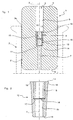
Figure 1 is a schematic view, in longitudinal section, of a first example of a stopper made according to the present invention, -
Figure 2 is a schematic view in longitudinal section and on an enlarged scale of a detail of the stopper ofFigure 1 , -
Figure 3 . is a schematic view in longitudinal section of a second example of a stopper made according to the present invention, -
Figure 4 is a schematic view in longitudinal section of a third example of a stopper made according to the present invention. - In
Figures 1 and 2 , the number 1 indicates the whole of a first example of a stopper, made according to the present invention, intended for sealing bottles of wine, particularly wine for ageing which requires a considerable period of maturing. - The stopper 1 comprises a
main body 2, of generally cylindrical shape with rounded edges and having dimensions such as to allow it to be housed and engaged in anaperture 3a of abottle 3 only partially indicated by broken lines inFigure 1 . - The
main body 2 is made from any polymer material having mechanical and sealing characteristics such that it is as impermeable as possible to liquids, gases and vapours such as expanded polyethylene, or polyolefin and styrene based copolymers, or elastomers in general. - A
passage 4 is formed in themain body 2 and extends along a longitudinal axis X of thebody 2, opening at its opposite ends which form a first surface 5 and asecond surface 6. When the stopper 1 is inserted into thebottle 3, the first andsecond surfaces 5 and 6 are intended to face the outside environment in one case, and the inside of the bottle in the other case, thus forming an outer surface and an inner surface of the stopper 1. Clearly, the stopper is of a two-way type; that is to say it can be inserted into the neck of the bottle in either of the two possible directions, so that the outer surface can be formed by the first surface 5 or by thesecond surface 6. - A permeable element is inserted into the
passage 4, to provide adequate regulation of the passage of oxygen between the inside and the outside of the bottle. This permeable element can be of the membrane type, as described in detail below with reference toFigures 1 and 2 , or can be of the insert type, that is to say a rod-like cylindrical body, extending predominantly along the axis of thepassage 4, as described below. - In the first preferred example described here, the
passage 4 comprises a first cylindrical portion of reduceddiameter 7, extending from thesecond surface 6 towards amedian portion 8 of thepassage 4, and asecond portion 9, also cylindrical but having a larger diameter, extending from themedian portion 8 towards the first surface 5. - The
median portion 8 is delimited towards thesecond portion 9 by a circular bead 10 extending radially towards the inside of thepassage 4, and it is delimited towards thefirst portion 7 by ashoulder 11. - The
median portion 8 has surfaces slightly inclined with respect to the axis X from the bead 10 to theshoulder 11, and forms a seat for housing asupport sleeve 12 whose shape is substantially conjugate with that of themedian portion 8. Thesleeve 12, shown in greater detail inFigure 2 , thus has a generally truncated conical shape with a profile tapered along the axis X from itsmajor base 13 to itsminor base 14. - In the
seat 8, thesleeve 12 is positioned with its minor base bearing on theshoulder 11 and with itsmajor base 13 next to the bead 10. - A through
hole 15, intercepted in its central area by amembrane 16 which extends transversely with respect to the axis X and is fixed to thesupport sleeve 12 by particular welding or moulding methods, is formed along the longitudinal axis of thesleeve 12, coinciding with the axis X. - The
membrane 16 therefore intercepts thehole 15 and consequently theentire passage 4 for communication between the first andsecond surfaces 5 and 6 of the stopper 1. The characteristics of themembrane 16, described in detail below, are such as to efficiently regulate the passage of gases and vapours, particularly oxygen, through thepassage 4. - In the specific case detailed here, the diameter of the
hole 15 is equal to that of thefirst portion 7, so as to form an extension thereof, but clearly it is possible for it to have a different diameter. Thehole 15 can also have different cross sections in the portions separated by themembrane 16. Aprojection 19, extending radially towards the walls of theseat 8 from the edge of themajor base 13, is also conveniently provided around the outer shell of thesleeve 12. - The
projection 19 preferably has a sharp edge, so that it can be more easily inserted into the walls of theseat 8. - The production of the stopper 1 comprises a first step of producing the
main body 2 of the suitable polymer material, with the provision of thepassage 4. This step can be carried out by injection moulding, extrusion, or any other method suitable for the purpose. - The
support sleeve 12 is made separately, for example by injection moulding of polypropylene, polyamide or ABS, and themembrane 16 is fixed therein. - The
membrane 16 can be fixed to thesleeve 12 in the most suitable way. For example; in the embodiment described here, the membrane is positioned on ashoulder 17 formed in thehole 15 and retained in position by atubular insert 18 bearing on theshoulder 17 and subsequently heat-welded. To improve the retention of the membrane, it is possible to create pointed formations (not shown in the figures) on theshoulder 17 and/or on thetubular insert 18, projecting towards themembrane 16, with a pressure retaining system of the flange type. - Similarly, the
membrane 16 can be fixed to thesleeve 12 by overmoulding the plastics material forming the sleeve on to the membrane which has previously been positioned in the mould, or by ultrasonic welding. In particular, the overmoulding method is particularly preferred if the polymer material forming thesleeve 12 and that forming themembrane 16 are chemically compatible with each other. - The
sleeve 12 is then inserted mechanically into thepassage 4 of themain body 2, until theminor base 14 bears on theshoulder 11, thus defining its correct position in theseat 8. - It should be noted that the step of inserting the
sleeve 12 is facilitated by its truncated conical shape and that the provision of the bead 10 prevents its movement out of themain body 2. When the stopper 1 is inserted and engaged in theaperture 3a of thebottle 3, the main body is normally subjected to radial compression which ensures that the stopper is retained in the sealing position, and that there is sufficient resistance to the passage of gases and liquids between the stopper and bottle. Following this compression, theprojection 19 is pressed forcefully against the walls of theseat 8, thus forming a means of preventing the passage of gases or liquids between thesleeve 12 and themain body 2, and an efficient means of fixing thesleeve 12 inside theseat 8. - The
membrane 16 is impermeable to liquids, and thus does not allow the passage of any liquids through it. - The
membrane 16 is also made from polymer material having characteristics such that it allows a sufficient flow of oxygen for the process of maturing the wine contained in the bottle, this flow being measured at approximately 0.1 - 5 milligrammes (mg) per month, depending on the type of wine. In particular, for most of the wines concerned, the monthly flow of oxygen which must pass from the outside to the inside of the bottle for the wine to mature correctly is in the range from 0.2 to 2 mg. - If suitable allowance is made for a minimum constant quantity of oxygen which inevitably passes between the stopper and the neck of the bottle, and if the same differential partial pressure of oxygen is assumed to exist between the two sides of the membrane, this flow depends substantially on the area of the membrane exposed to the flow, on its thickness and on its permeability to oxygen.
- The area of the
membrane 16 exposed to the flow of oxygen is identical, in the case described here, to the area of the cross section of thehole 15, whose diameter varies from approximately 0.1 to 10 mm, preferably from 1 mm to 7 mm. The area concerned is therefore in the range from 0.0078 to 78.5 mm2, preferably from 0.7 to 38.5 mm2. - On the other hand, the thickness of the
membrane 16 is in the range from 5 to 2000 microns, preferably from 10 to 1000 microns. If the membrane has a thickness of less than about 100 microns, it is preferably placed on a supporting material, for example a suitably treated paper-based material, whose characteristics must be such as not to affect the permeability of the membrane. - Additionally, in the case of membranes of a certain thickness, the
membrane 16 can be moulded in one piece with thesleeve 12, thus forming a monolithic permeable element made from a single material. - It should be noted that, in the preferred case described here, there is only one membrane. However, it is possible to control the flow of oxygen by providing more than one membrane. In this case, it must be possible to provide an equivalent total area and an equivalent total thickness, defined as the surface and thickness of a hypothetical membrane which by itself would offer the same resistance to the flow of oxygen as the plurality of membranes provided in the stopper.
- The determination of this equivalent total area and thickness will clearly depend on the way in which the membranes are positioned in the stopper, for example on whether they are positioned in series in the same passage or in parallel in different passages.
- The oxygen permeability of the
membrane 16 at ambient temperature, fixed at 20°C, is in the range from 10-7 to 10-11 (Ncm3*cm/cm2*cmHg*s). - The
membrane 16 is of a compact type, in other words having substantially no porosity, in which case the flow of the gas concerned through the membrane takes place by diffusion in the polymer matrix. - Membranes of the compact type having levels of permeability within the aforesaid limits may, for example, be based on silicone rubber such as vulcanized polydimethylsiloxane (PDMS) or poly(oxydimethylsilylene). Silicone rubbers have poor chemical compatibility with the polypropylene from which the
sleeve 12 is preferably made, and therefore membranes made from this material are typically kept engaged in thesleeve 12 by the method described above with reference toFigures 1 and 2 . - Additionally, if the material of the membrane is a silicone rubber, the membrane and the sleeve can be formed in one piece by a single moulding operation, forming a monolithic permeable element.
- Other examples, provided for information and not intended to be exhaustive, of materials suitable for making membranes of the compact type include:
- polydienes and their copolymers, such as polybutadiene, polyisoprene, polyisoprene hydrochloride, polymethyl-1-pentenylene, hydrogenated polybutadiene, poly(2-methyl-1,3-pentadiene-co-4-methyl-1,3-pentadiene), vulcanized trans rubber, polychloroprene and butadiene-acrylonitrile copolymer;
- cellulose derivatives, such as ethylcellulose and cellulose acetobutyrate,
- styrene/olefin/diene-based copolymers such as styrene-ethylene-butene-styrene (SEBS) and styrene-ethylene-propylene-styrene (SEPS),
- polyoxides, such as poly(oxy-2,6-dimethyl-1,4-phenylene),
- polyolefins and their derivatives, such as low-density polyethylene or ethylene-vinylacetate copolymer (EVA),
- fluoridated polymers and copolymers, such as polytetrafluoroethylene and tetrafluoroethylene-hexafluoropropylene copolymer.
- Some examples of membranes made from these materials are given in the table appended to the description.
- The materials listed above are also more chemically compatible with polypropylene than are silicone rubbers, and they can therefore be overmoulded for the formation of the
sleeve 12. - The
membrane 16 can be of the composite type, formed by a single layer or by a plurality of superimposed layers, each of which can be made from any polymer, homopolymer, or polymer or copolymer mixture, which may be of a composite type and filled with inorganic filler. One of the layers can also consist of an inorganic, ceramic or zeolite material. - The materials forming the aforesaid membranes can be suitably nano-filled, for example with organomodified nanoclays, silica, TiO2, magnesium oxide, titanium dioxide, etc., to achieve the desired oxygen permeability.
- For microporous membranes (including nanoporous membranes), the membrane must, according to another aspect of the invention, have a molecular cut-off of less than 50 kDalton.
- The molecular cut-off is a measurement correlated with the dimension of the micropores and indicates the maximum molecular weight of molecules capable of passing through the membrane by travelling through its holes.
- The measurement of the dimension of the micropores is of considerable importance if the stopper 1 is used in bottles containing wine intended for a long maturing process. This is because a low molecular cut-off substantially impedes the passage of complex heavy molecules from and to the inside of the bottle, including molecules of compounds important for the conservation and/or production of the final flavour properties required in the wine contained in the bottle, and also including spores, moulds and bacteria.
- In particular, the microporous membrane preferably has a molecular cut-off in the range from 1 to 30 kDalton, or more preferably in the range from 1 to 10 kDalton.
- Microporous membranes having the characteristics specified above can be made, for example, from polytetrafluoroethylene (PTFE) and have a thickness ranging from 100 to 500 microns. Their chemical compatibility with polypropylene is also sufficient to enable them to be fixed to the
sleeve 12 by an overmoulding method. - According to another aspect of the invention, the
membrane 16 also preferably has a water vapour permeability, measured at 23°C, in the range from 50 to 500 g/m2d, a value at which the loss of water over time can be sufficiently controlled. - A set of stoppers were prepared according to the above teachings, using membranes with compact materials, with different permeability, and having different areas and thicknesses.
- All the examples of stoppers made were tested under constant pressure and temperature, comparable with the environmental conditions in which the process of maturing a wine in the bottle normally takes place.
- The test results are shown in Table 1, which lists the monthly flows of oxygen through a stopper having a membrane made from a material with a permeability indicated as Perm, a thickness indicated as S, in microns, and a specific diameter indicated as D, in mm.
- The results which meet the flow requirements for a correct ageing process of the wine are those in the range from 0.1 to 2 mg/month, which, allowing for an oxygen exchange of approximately 0.1 mg/month through the tested stopper and the bottle neck, conform to the optimal exchange conditions for maturing a vintage wine.
- All the materials used, the surface dimensions, the thicknesses and the measured oxygen flows are shown in Table 1 which is provided for the purposes of this description. The positive results, in other words those relating to a flow within the aforementioned range, are shown in bold type. The results in Table 1 demonstrate that silicone rubbers require greater thicknesses, in the region of 500 microns, in order to be suitable for the required purpose, while other polymer materials must have smaller thicknesses, of approximately 100 microns, or even as little as 10 microns.
- A
stopper 100 made according to a second example of the present invention is shown inFigure 3 , in which details similar to details of the preceding example are identified by the same reference numerals. - In the
stopper 100, the permeable element, in this case in the form of amembrane 101, is made from the same material as themain body 2, and is produced simultaneously with it, by a moulding method. - Clearly, this solution enables the production costs to be considerably reduced, since only one material and one operation are required, with no need for subsequent working or assembly.
- This material must of course have not only the appropriate permeability but also all the necessary mechanical, chemical and physical, and workability characteristics for its use in the production of the
main body 2. - A preferred example of this material consists of SEBS copolymer and SEPS copolymer. By using this material, it is possible to mould the
main body 2, in one piece in a single operation, thepassage 4, sealed by amembrane 16 of suitable thickness, being formed inside the main body. In particular, where the size of thepassage 4 is approximately 7 mm, themembrane 16 has a thickness of approximately 1000 microns, which is large enough to allow the moulding method to be used. - In a third example of embodiment of the present invention, shown in
Figure 4 , which represents astopper 200, the permeable element is of the insert type, in other words having a rod-like body 201 whose cross section is conjugate with that of thepassage 4. - In this case, the predominant dimension of the permeable element is the axial dimension, which can be in the range from 2 mm to 60 mm, while the cross sections of the
passage 4 are similar to those of the preceding example. - In this case, since the thickness of the permeable element is greater by approximately two orders of magnitude than the thickness of the membranes of the preceding example, the permeability required in the material forming the permeable element is, correspondingly, greater by approximately two orders of magnitude, being preferably in the range from 10-5 to 10-9 (Ncm3*cm/cm2*cmHg*s). Preferably, the insert is of the compact type.
- Thus the present invention resolves the problem of the prior art identified above, while also offering numerous other benefits.
TABLE 1 Material Perm
Ncm3*cm/ (cm2*cmHg*s)Oxygen flow (mg/month) S=10µ
D=1mmS=10µ
D=1.5mmS=10µ
D=2mmS=100µ
D=1mmS=100u
D=1.5mmS=100µ
D=2mmS=500µ
D=1mmS=500µ
D=1.5mmS=500µ
D=2mmS=250µ
D=5mmS=1000µ
D=7mmPDMS 8.00E-08 37.18 83.66 148.72 3.72 8.37 14.87 0.74 1.67 2.97 37.18 18.21 Poly(oxydimethylsilylene) with 10% Scantocel CS filler 4.88E-08 22.68 51.04 90.74 2.27 5.1 9.07 0.45 1.02 1.81 22.68 11.12 SEPS (Megol K) 1.88E-08 8.74 19.66 34.95 0.87 1.97 3.49 0.17 0.39 0.70 8.74 4.28 Polyisoprene hydrochloride 5.39E-09 2.50 5.63 10.01 0.25 0.56 1.00 0.05 0.11 0.20 2.50 1.23 Polymethyl-1-pentenylene 3.22E-09 1.50 3.37 5.98 0.15 0.34 0.60 0.03 0.07 0.12 1.50 0.73 Polyisoprene, amorphous 2.34E-09 1.09 2.45 4.35 0.11 0.24 0.44 0.02 0.05 0.09 1.09 0.53 Polybutadiene 1.90E-09 0.88 1.99 3.54 0.09 0.20 0.35 0.02 0.04 0.07 0.88 0.43 SEBS (Kraton G1650) 1.39E-09 0.64 1.44 2.57 0.06 0.14 0.26 0.01 0.03 0.05 0.64 0.32 SEBS (Kraton G2705) 2.51E-09 1.16 2.62 4.66 0.12 0.26 0.47 0.02 0.05 0.09 1.16 0.57 Poly(oxy-2,6-dimethyl-1,4-phenylene) 1.58E-09 0.74 1.66 2.94 0.07 0.17 0.29 0.01 0.03 0.06 0.74 0.36 Ethyl cellulose 1.46E-09 0.68 1.53 2.73 0.07 0.15 0.27 0.01 0.03 0.05 0.68 0.33 Hydrogenated polybutadiene 1.13E-09 0.52 1.18 2.10 0.05 0.12 0.21 0.01 0.02 0.04 0.52 0.26 Poly (2-methyl-1,3-pentadiene-co-4-methyl-1,3-pentadiene) 85/15 1.00E-09 0.46 1.05 1.86 0.05 0.10 0.19 0.01 0.02 0.03 0.46 0.23 Polybutadiene-co-acrylonitrife 80/20 8.18E-10 0.38 0.86 1.52 0.04 0.09 0.15 0.01 0.02 0.03 0.38 0.19 Purified vulcanized trans rubber, qutta percha 6.17E-10 0.29 0.65 1.15 0.03 0.06 0.11 0.01 0.01 0.02 0.29 0.14 Polytetrafluoroethylene-co-hexafluoropropene 4.89E-10 0.23 0.51 0.91 0.02 0.05 0.09 0.00 0.01 0.02 0.23 0.11 Cellulose acetobutyrate 4.73E-10 0.22 0.50 0.88 0.02 0.05 0.09 0.00 0.01 0.02 0.22 0.11 Polytetrafluoroethylene (PTFE) 4.26E-10 0.20 0.45 0.79 0.02 0.04 0.08 0.00 0.01 0.02 0.20 0.10 Fluoridated polymer 4.22E-10 0.20 0.44 0.78 0.02 0.04 0.08 0.00 0.01 0.01 0.20 0.10 Polychloroprene 3.94E-10 0.18 0.41 0.73 0.02 0.04 0.07 0.00 0.01 0.01 0.18 0.09 Polybutadiene-co-acrylonitrile 73/27 3.86E-10 0.18 0.40 0.72 0.02 0.04 0.07 0.00 0.01 0.01 0.18 0.09 LDPE (low-density polyethylene) 2.93E-10 0.14 0.31 0.54 0.01 0.03 0.05 0.00 0.01 0.01 0.14 0.07
Claims (23)
- Stopper (1, 100, 200) for sealing bottles (3), particularly for sealing bottles of wine for ageing, comprising:- a main body (2) shaped in such a way as to be removably housed in engagement in an aperture (3a) of the said bottles,- a first surface (5) and a second surface (6) formed on the said main body and facing, respectively, the outside and the inside of the said bottles when the said main body is received in engagement in the said aperture,- at least one passage (4) extending between the said first and second surfaces and capable of making the inside of the said bottles communicate with the environment outside the bottles,wherein the stopper comprises a permeable element (16, 101, 201) which is impermeable to liquids and permeable to oxygen, the said permeable element being extended to seal the said passage in order to regulate the flow of oxygen between the inside and the outside of the bottle, the said permeable element having an oxygen permeability, measured at 20°C, in the range from 10-7 to 10-11 (Ncm3*cm/cm2*cmHg*s) characterised in that said permeable element is of the compact type, having substantially no porosity and in which the flow of oxygen takes place by diffusion.
- Stopper according to Claim 1, in which said permeable element comprises at least one membrane (16) having an oxygen permeability, measured at 20°C, in the range from 10-7 to 10-11 (Ncm3*cm/cm2*cmHg*s).
- Stopper according to Claim 2, in which the said membrane is of the compact type and is made from a material selected from a group composed of silicone rubbers, polydienes and their copolymers, cellulose derivatives, styrene/olefin/diene-based copolymers, polyoxides, polyolefins and their derivatives, and fluoridated polymers and copolymers.
- Stopper according to Claim 3, in which the said membrane is made from a material selected from a group composed of polybutadiene, polyisoprene, polyisoprene hydrochloride, polymethyl-1-pentenylene, ethyl cellulose, styrene-ethylene-butene-styrene copolymer (SEBS), styrene-ethylene-propylene-styrene copolymer (SEPS), poly(oxy-2,6-dimethyl-1,4-phenylene), hydrogenated polybutadiene, poly(2-methyl-1,3-pentadiene-co-4-methyl-1,3-pentadiene), butadiene-acrylonitrile copolymer, vulcanized trans rubber, tetrafluoroethylene-hexafluoropropene copolymer, cellulose acetobutyrate, fluoridated polymers such as polytetrafluoroethylene, polychloroprene, low-density polyethylene, and ethylene vinylacetate copolymer (EVA).
- Stopper according to Claim 4, in which the said membrane is based on silicone rubber, SEBS, SEPS or EVA.
- Stopper according to any one or more of Claims 2 to 5, in which the said at least one membrane has a total equivalent area for the passage of oxygen, the said total equivalent area being in the range from 0.0078 to 78.5 mm2.
- Stopper according to Claim 6, in which the said total equivalent area is in the range from 0.78 to 38.5 mm2.
- Stopper according to any one or more of the preceding claims, in which the said at least one membrane has a total equivalent thickness of the area through which oxygen passes, the said total equivalent thickness being in the range from 5 to 2000 microns.
- Stopper according to Claim 8, in which the said total equivalent thickness is in the range from 10 to 1000 microns.
- Stopper according to any one or more of the preceding claims, in which the said membrane has a water vapour permeability measured at 23°C in the range from 50 to 500 (g/m2d).
- Stopper according to any one or more of Claims 3 to 10, in which the said main body (2) and the said membrane (101) are made in one piece from the same material.
- Stopper according to Claim 11, in which the said main body and the said membrane are made from SEBS copolymer or from SEPS copolymer or from EVA.
- Stopper according to any one or more of Claims 2 to 12, in which the said membrane is fixed in a support sleeve (12) which in turn is fixed inside the said passage.
- Stopper according to Claim 13, in which a seat (8) for housing the said support sleeve is provided the said passage.
- Stopper according to Claim 14, in which the said seat is longitudinally delimited by a bead (10) extending radially from the said main body towards the said passage, and by a shoulder (11) formed in the said passage.
- Stopper according to any one or more of Claims 13 to 15, in which the said sleeve (12) has a profile tapered along a longitudinal axis (X) of the said passage.
- Stopper according to any one or more of Claims 13 to 16, in which the said sleeve comprises a projection (19) extending radially around its outer shell so as to increase the security of fixing between the said sleeve (12) and the said main body (2).
- Stopper according to Claim 17, in which the said sleeve has a truncated conical profile and the said projection extends from the major base (13) of the said sleeve.
- Stopper according to Claim 18, in which the said projection has a sharp edge facing the walls of the said passage.
- Stopper according to any one or more of Claims 13 to 19, in which the said membrane is fixed in the said support sleeve by overmoulding the said sleeve on to the said membrane.
- Stopper according to any one or more of Claims 13 to 19, in which the said membrane is made in one piece with the said support sleeve.
- Stopper according to Claim 1, in which the said permeable element comprises an insert (201) with a predominant axial dimension, having an oxygen permeability measured at 20°C in the range from 10-5 to 10-9 (Ncm3*cm/cm2*cmHg*s).
- Stopper according to Claim 22, in which the said insert has a total equivalent area in the range from 0.7 to 78.5 mm2 and a total equivalent thickness in the range from 2 to 60 millimetres.
Applications Claiming Priority (2)
| Application Number | Priority Date | Filing Date | Title |
|---|---|---|---|
| IT000336A ITPD20050336A1 (en) | 2005-11-22 | 2005-11-22 | CAP FOR CLOSING BOTTLES, PARTICULARLY FOR THE CLOSING OF BOTTLES OF WINE FROM AGING |
| PCT/IT2006/000813 WO2007060706A1 (en) | 2005-11-22 | 2006-11-21 | Stopper for sealing bottles, particularly for sealing bottles of wine for ageing |
Publications (2)
| Publication Number | Publication Date |
|---|---|
| EP1951589A1 EP1951589A1 (en) | 2008-08-06 |
| EP1951589B1 true EP1951589B1 (en) | 2010-09-08 |
Family
ID=37807762
Family Applications (1)
| Application Number | Title | Priority Date | Filing Date |
|---|---|---|---|
| EP06832330A Not-in-force EP1951589B1 (en) | 2005-11-22 | 2006-11-21 | Stopper for sealing bottles, particularly for sealing bottles of wine for ageing |
Country Status (12)
| Country | Link |
|---|---|
| US (1) | US20080257853A1 (en) |
| EP (1) | EP1951589B1 (en) |
| CN (1) | CN101316768A (en) |
| AT (1) | ATE480468T1 (en) |
| AU (1) | AU2006318005A1 (en) |
| CL (1) | CL2008001416A1 (en) |
| DE (1) | DE602006016844D1 (en) |
| ES (1) | ES2352084T3 (en) |
| IT (1) | ITPD20050336A1 (en) |
| RU (1) | RU2008125087A (en) |
| WO (1) | WO2007060706A1 (en) |
| ZA (1) | ZA200804385B (en) |
Families Citing this family (8)
| Publication number | Priority date | Publication date | Assignee | Title |
|---|---|---|---|---|
| WO2008015656A2 (en) * | 2006-08-02 | 2008-02-07 | The Procter & Gamble Company | Venting bottle closure |
| US20120067842A1 (en) * | 2010-03-19 | 2012-03-22 | Keller Timothy P | Oxygen regulation mechanism for a beverage gasket |
| DE102018003669A1 (en) | 2017-07-20 | 2019-01-24 | Ten-Ace Gmbh | drinking device |
| DE102018222299A1 (en) | 2018-12-19 | 2020-06-25 | Ten-Ace Gmbh | Drinking device |
| IT201900011322A1 (en) * | 2019-07-10 | 2021-01-10 | Matteo Alessandro Frati | CAP FOR BOTTLES |
| AU2020448180A1 (en) | 2020-05-18 | 2022-12-15 | air up group GmbH | Aroma container and drinking device having an aroma container |
| FR3124497B1 (en) * | 2021-06-24 | 2024-03-08 | Diam Bouchage | Cap having gas permeability control and corresponding manufacturing process |
| IT202100030356A1 (en) * | 2021-11-30 | 2023-05-30 | Flon Project S R L | A CAP MADE OF A CLOSED CELL POLYMER COMPOSITE MATERIAL PROVIDED WITH AN AIR PASSAGE DUCT OBSTRUCTED BY AN e-PTFE MATERIAL |
Family Cites Families (8)
| Publication number | Priority date | Publication date | Assignee | Title |
|---|---|---|---|---|
| BE561646A (en) * | ||||
| CH687694A5 (en) * | 1993-06-18 | 1997-01-31 | Benno Nussbaumer | Multipart closure stopper made of plastic for bottles of wine or wine drinks. |
| DE10029760A1 (en) * | 2000-06-16 | 2002-01-03 | Kador Utz | closure device |
| US6536618B1 (en) * | 2000-10-31 | 2003-03-25 | Hsu-Rong Hwang | Bottle plug |
| ITVI20010180A1 (en) * | 2001-08-30 | 2003-03-02 | Marco Musaragno | CAP FOR THE BOTTLING OF PRECIOUS WINES, PARTICULARLY SUITABLE FOR THE STORAGE AND REFINING OF THE PRODUCT |
| GB0317557D0 (en) * | 2003-07-26 | 2003-08-27 | Univ Manchester | Microporous polymer material |
| EP1541482A1 (en) * | 2003-12-09 | 2005-06-15 | Vintec S.r.l | Low permeability device for closure of barrels |
| US7410525B1 (en) * | 2005-09-12 | 2008-08-12 | Uop Llc | Mixed matrix membranes incorporating microporous polymers as fillers |
-
2005
- 2005-11-22 IT IT000336A patent/ITPD20050336A1/en unknown
-
2006
- 2006-11-21 AT AT06832330T patent/ATE480468T1/en active
- 2006-11-21 CN CNA2006800430709A patent/CN101316768A/en active Pending
- 2006-11-21 AU AU2006318005A patent/AU2006318005A1/en not_active Abandoned
- 2006-11-21 US US12/094,283 patent/US20080257853A1/en not_active Abandoned
- 2006-11-21 DE DE602006016844T patent/DE602006016844D1/en active Active
- 2006-11-21 EP EP06832330A patent/EP1951589B1/en not_active Not-in-force
- 2006-11-21 RU RU2008125087/12A patent/RU2008125087A/en not_active Application Discontinuation
- 2006-11-21 ES ES06832330T patent/ES2352084T3/en active Active
- 2006-11-21 WO PCT/IT2006/000813 patent/WO2007060706A1/en not_active Ceased
- 2006-11-21 ZA ZA200804385A patent/ZA200804385B/en unknown
-
2008
- 2008-05-15 CL CL2008001416A patent/CL2008001416A1/en unknown
Also Published As
| Publication number | Publication date |
|---|---|
| ATE480468T1 (en) | 2010-09-15 |
| DE602006016844D1 (en) | 2010-10-21 |
| ITPD20050336A1 (en) | 2007-05-23 |
| AU2006318005A1 (en) | 2007-05-31 |
| ZA200804385B (en) | 2009-08-26 |
| CN101316768A (en) | 2008-12-03 |
| US20080257853A1 (en) | 2008-10-23 |
| RU2008125087A (en) | 2009-12-27 |
| WO2007060706A1 (en) | 2007-05-31 |
| CL2008001416A1 (en) | 2009-01-16 |
| EP1951589A1 (en) | 2008-08-06 |
| ES2352084T3 (en) | 2011-02-15 |
Similar Documents
| Publication | Publication Date | Title |
|---|---|---|
| EP2865606B1 (en) | Mechanical clamping caps for the closure of bottles | |
| RU2268213C2 (en) | Plug for vine bottling | |
| US20080257853A1 (en) | Stopper For Sealing Bottles, Particularly For Sealing Bottles of Wine For Ageing | |
| AU2003243374B2 (en) | Vented closures for containers | |
| EP3225378B1 (en) | Preform for biaxial stretching blow molding, and container | |
| AU2002220942A1 (en) | Stopper for bottling wines | |
| US20080290062A1 (en) | Oxidation suppressing stopper for wine | |
| CN103534036A (en) | Liquid dispensing device equipped with an air duct | |
| CN116194203A (en) | breather | |
| EP3645410A1 (en) | Screw cap for wine bottles | |
| CN118701507A (en) | A DIY packaging bottle for ready-mixed cocktails | |
| US3106306A (en) | Bottle of plastic material and closure member therefor | |
| CN101549767A (en) | Bottle stopper with air permeability | |
| IT202100030356A1 (en) | A CAP MADE OF A CLOSED CELL POLYMER COMPOSITE MATERIAL PROVIDED WITH AN AIR PASSAGE DUCT OBSTRUCTED BY AN e-PTFE MATERIAL | |
| NZ574167A (en) | Closure for wine bottle with line having specified oxygen transmission rate | |
| EP1541482A1 (en) | Low permeability device for closure of barrels | |
| IT201900011322A1 (en) | CAP FOR BOTTLES | |
| ITMI20062359A1 (en) | SYNTHETIC MATERIAL CAP FOR GLASS BOTTLES | |
| JP2002045655A (en) | Fluid separation element |
Legal Events
| Date | Code | Title | Description |
|---|---|---|---|
| PUAI | Public reference made under article 153(3) epc to a published international application that has entered the european phase |
Free format text: ORIGINAL CODE: 0009012 |
|
| 17P | Request for examination filed |
Effective date: 20080512 |
|
| AK | Designated contracting states |
Kind code of ref document: A1 Designated state(s): AT BE BG CH CY CZ DE DK EE ES FI FR GB GR HU IE IS IT LI LT LU LV MC NL PL PT RO SE SI SK TR |
|
| 17Q | First examination report despatched |
Effective date: 20090302 |
|
| GRAP | Despatch of communication of intention to grant a patent |
Free format text: ORIGINAL CODE: EPIDOSNIGR1 |
|
| RIN1 | Information on inventor provided before grant (corrected) |
Inventor name: CAPPELLO, GIOVANNI |
|
| GRAS | Grant fee paid |
Free format text: ORIGINAL CODE: EPIDOSNIGR3 |
|
| GRAA | (expected) grant |
Free format text: ORIGINAL CODE: 0009210 |
|
| DAX | Request for extension of the european patent (deleted) | ||
| AK | Designated contracting states |
Kind code of ref document: B1 Designated state(s): AT BE BG CH CY CZ DE DK EE ES FI FR GB GR HU IE IS IT LI LT LU LV MC NL PL PT RO SE SI SK TR |
|
| REG | Reference to a national code |
Ref country code: GB Ref legal event code: FG4D |
|
| REG | Reference to a national code |
Ref country code: CH Ref legal event code: EP |
|
| REG | Reference to a national code |
Ref country code: IE Ref legal event code: FG4D |
|
| REF | Corresponds to: |
Ref document number: 602006016844 Country of ref document: DE Date of ref document: 20101021 Kind code of ref document: P |
|
| REG | Reference to a national code |
Ref country code: NL Ref legal event code: VDEP Effective date: 20100908 |
|
| PG25 | Lapsed in a contracting state [announced via postgrant information from national office to epo] |
Ref country code: LT Free format text: LAPSE BECAUSE OF FAILURE TO SUBMIT A TRANSLATION OF THE DESCRIPTION OR TO PAY THE FEE WITHIN THE PRESCRIBED TIME-LIMIT Effective date: 20100908 Ref country code: FI Free format text: LAPSE BECAUSE OF FAILURE TO SUBMIT A TRANSLATION OF THE DESCRIPTION OR TO PAY THE FEE WITHIN THE PRESCRIBED TIME-LIMIT Effective date: 20100908 |
|
| REG | Reference to a national code |
Ref country code: ES Ref legal event code: FG2A Effective date: 20110203 |
|
| LTIE | Lt: invalidation of european patent or patent extension |
Effective date: 20100908 |
|
| PG25 | Lapsed in a contracting state [announced via postgrant information from national office to epo] |
Ref country code: SI Free format text: LAPSE BECAUSE OF FAILURE TO SUBMIT A TRANSLATION OF THE DESCRIPTION OR TO PAY THE FEE WITHIN THE PRESCRIBED TIME-LIMIT Effective date: 20100908 Ref country code: CY Free format text: LAPSE BECAUSE OF FAILURE TO SUBMIT A TRANSLATION OF THE DESCRIPTION OR TO PAY THE FEE WITHIN THE PRESCRIBED TIME-LIMIT Effective date: 20100908 Ref country code: PL Free format text: LAPSE BECAUSE OF FAILURE TO SUBMIT A TRANSLATION OF THE DESCRIPTION OR TO PAY THE FEE WITHIN THE PRESCRIBED TIME-LIMIT Effective date: 20100908 |
|
| PGFP | Annual fee paid to national office [announced via postgrant information from national office to epo] |
Ref country code: DE Payment date: 20101119 Year of fee payment: 5 |
|
| PG25 | Lapsed in a contracting state [announced via postgrant information from national office to epo] |
Ref country code: LV Free format text: LAPSE BECAUSE OF FAILURE TO SUBMIT A TRANSLATION OF THE DESCRIPTION OR TO PAY THE FEE WITHIN THE PRESCRIBED TIME-LIMIT Effective date: 20100908 Ref country code: SE Free format text: LAPSE BECAUSE OF FAILURE TO SUBMIT A TRANSLATION OF THE DESCRIPTION OR TO PAY THE FEE WITHIN THE PRESCRIBED TIME-LIMIT Effective date: 20100908 Ref country code: GR Free format text: LAPSE BECAUSE OF FAILURE TO SUBMIT A TRANSLATION OF THE DESCRIPTION OR TO PAY THE FEE WITHIN THE PRESCRIBED TIME-LIMIT Effective date: 20101209 Ref country code: NL Free format text: LAPSE BECAUSE OF FAILURE TO SUBMIT A TRANSLATION OF THE DESCRIPTION OR TO PAY THE FEE WITHIN THE PRESCRIBED TIME-LIMIT Effective date: 20100908 |
|
| PGFP | Annual fee paid to national office [announced via postgrant information from national office to epo] |
Ref country code: GB Payment date: 20101118 Year of fee payment: 5 |
|
| PG25 | Lapsed in a contracting state [announced via postgrant information from national office to epo] |
Ref country code: CZ Free format text: LAPSE BECAUSE OF FAILURE TO SUBMIT A TRANSLATION OF THE DESCRIPTION OR TO PAY THE FEE WITHIN THE PRESCRIBED TIME-LIMIT Effective date: 20100908 Ref country code: PT Free format text: LAPSE BECAUSE OF FAILURE TO SUBMIT A TRANSLATION OF THE DESCRIPTION OR TO PAY THE FEE WITHIN THE PRESCRIBED TIME-LIMIT Effective date: 20110110 Ref country code: IS Free format text: LAPSE BECAUSE OF FAILURE TO SUBMIT A TRANSLATION OF THE DESCRIPTION OR TO PAY THE FEE WITHIN THE PRESCRIBED TIME-LIMIT Effective date: 20110108 Ref country code: RO Free format text: LAPSE BECAUSE OF FAILURE TO SUBMIT A TRANSLATION OF THE DESCRIPTION OR TO PAY THE FEE WITHIN THE PRESCRIBED TIME-LIMIT Effective date: 20100908 Ref country code: SK Free format text: LAPSE BECAUSE OF FAILURE TO SUBMIT A TRANSLATION OF THE DESCRIPTION OR TO PAY THE FEE WITHIN THE PRESCRIBED TIME-LIMIT Effective date: 20100908 Ref country code: EE Free format text: LAPSE BECAUSE OF FAILURE TO SUBMIT A TRANSLATION OF THE DESCRIPTION OR TO PAY THE FEE WITHIN THE PRESCRIBED TIME-LIMIT Effective date: 20100908 |
|
| PG25 | Lapsed in a contracting state [announced via postgrant information from national office to epo] |
Ref country code: MC Free format text: LAPSE BECAUSE OF NON-PAYMENT OF DUE FEES Effective date: 20101130 Ref country code: BE Free format text: LAPSE BECAUSE OF FAILURE TO SUBMIT A TRANSLATION OF THE DESCRIPTION OR TO PAY THE FEE WITHIN THE PRESCRIBED TIME-LIMIT Effective date: 20100908 |
|
| REG | Reference to a national code |
Ref country code: CH Ref legal event code: PL |
|
| PLBE | No opposition filed within time limit |
Free format text: ORIGINAL CODE: 0009261 |
|
| STAA | Information on the status of an ep patent application or granted ep patent |
Free format text: STATUS: NO OPPOSITION FILED WITHIN TIME LIMIT |
|
| PG25 | Lapsed in a contracting state [announced via postgrant information from national office to epo] |
Ref country code: CH Free format text: LAPSE BECAUSE OF NON-PAYMENT OF DUE FEES Effective date: 20101130 Ref country code: LI Free format text: LAPSE BECAUSE OF NON-PAYMENT OF DUE FEES Effective date: 20101130 |
|
| 26N | No opposition filed |
Effective date: 20110609 |
|
| PG25 | Lapsed in a contracting state [announced via postgrant information from national office to epo] |
Ref country code: DK Free format text: LAPSE BECAUSE OF FAILURE TO SUBMIT A TRANSLATION OF THE DESCRIPTION OR TO PAY THE FEE WITHIN THE PRESCRIBED TIME-LIMIT Effective date: 20100908 |
|
| REG | Reference to a national code |
Ref country code: DE Ref legal event code: R097 Ref document number: 602006016844 Country of ref document: DE Effective date: 20110609 |
|
| PG25 | Lapsed in a contracting state [announced via postgrant information from national office to epo] |
Ref country code: IE Free format text: LAPSE BECAUSE OF NON-PAYMENT OF DUE FEES Effective date: 20101121 |
|
| PG25 | Lapsed in a contracting state [announced via postgrant information from national office to epo] |
Ref country code: BG Free format text: LAPSE BECAUSE OF FAILURE TO SUBMIT A TRANSLATION OF THE DESCRIPTION OR TO PAY THE FEE WITHIN THE PRESCRIBED TIME-LIMIT Effective date: 20100908 Ref country code: LU Free format text: LAPSE BECAUSE OF NON-PAYMENT OF DUE FEES Effective date: 20101121 Ref country code: HU Free format text: LAPSE BECAUSE OF FAILURE TO SUBMIT A TRANSLATION OF THE DESCRIPTION OR TO PAY THE FEE WITHIN THE PRESCRIBED TIME-LIMIT Effective date: 20110309 |
|
| PG25 | Lapsed in a contracting state [announced via postgrant information from national office to epo] |
Ref country code: TR Free format text: LAPSE BECAUSE OF FAILURE TO SUBMIT A TRANSLATION OF THE DESCRIPTION OR TO PAY THE FEE WITHIN THE PRESCRIBED TIME-LIMIT Effective date: 20100908 |
|
| PGFP | Annual fee paid to national office [announced via postgrant information from national office to epo] |
Ref country code: FR Payment date: 20121130 Year of fee payment: 7 |
|
| PGFP | Annual fee paid to national office [announced via postgrant information from national office to epo] |
Ref country code: ES Payment date: 20121127 Year of fee payment: 7 |
|
| REG | Reference to a national code |
Ref country code: AT Ref legal event code: MM01 Ref document number: 480468 Country of ref document: AT Kind code of ref document: T Effective date: 20121121 |
|
| GBPC | Gb: european patent ceased through non-payment of renewal fee |
Effective date: 20121121 |
|
| PG25 | Lapsed in a contracting state [announced via postgrant information from national office to epo] |
Ref country code: AT Free format text: LAPSE BECAUSE OF NON-PAYMENT OF DUE FEES Effective date: 20121121 |
|
| REG | Reference to a national code |
Ref country code: DE Ref legal event code: R119 Ref document number: 602006016844 Country of ref document: DE Effective date: 20130601 |
|
| PG25 | Lapsed in a contracting state [announced via postgrant information from national office to epo] |
Ref country code: BG Free format text: LAPSE BECAUSE OF FAILURE TO SUBMIT A TRANSLATION OF THE DESCRIPTION OR TO PAY THE FEE WITHIN THE PRESCRIBED TIME-LIMIT Effective date: 20101208 |
|
| PG25 | Lapsed in a contracting state [announced via postgrant information from national office to epo] |
Ref country code: DE Free format text: LAPSE BECAUSE OF NON-PAYMENT OF DUE FEES Effective date: 20130601 |
|
| PG25 | Lapsed in a contracting state [announced via postgrant information from national office to epo] |
Ref country code: GB Free format text: LAPSE BECAUSE OF NON-PAYMENT OF DUE FEES Effective date: 20121121 |
|
| REG | Reference to a national code |
Ref country code: FR Ref legal event code: ST Effective date: 20140731 |
|
| PG25 | Lapsed in a contracting state [announced via postgrant information from national office to epo] |
Ref country code: FR Free format text: LAPSE BECAUSE OF NON-PAYMENT OF DUE FEES Effective date: 20131202 |
|
| REG | Reference to a national code |
Ref country code: ES Ref legal event code: FD2A Effective date: 20150330 |
|
| PGFP | Annual fee paid to national office [announced via postgrant information from national office to epo] |
Ref country code: IT Payment date: 20141020 Year of fee payment: 9 |
|
| PG25 | Lapsed in a contracting state [announced via postgrant information from national office to epo] |
Ref country code: ES Free format text: LAPSE BECAUSE OF NON-PAYMENT OF DUE FEES Effective date: 20131122 |
|
| PG25 | Lapsed in a contracting state [announced via postgrant information from national office to epo] |
Ref country code: IT Free format text: LAPSE BECAUSE OF NON-PAYMENT OF DUE FEES Effective date: 20151121 |