EP1950460A2 - Engine unit and straddle-type vehicle provided with the same - Google Patents
Engine unit and straddle-type vehicle provided with the same Download PDFInfo
- Publication number
- EP1950460A2 EP1950460A2 EP08250286A EP08250286A EP1950460A2 EP 1950460 A2 EP1950460 A2 EP 1950460A2 EP 08250286 A EP08250286 A EP 08250286A EP 08250286 A EP08250286 A EP 08250286A EP 1950460 A2 EP1950460 A2 EP 1950460A2
- Authority
- EP
- European Patent Office
- Prior art keywords
- shaft
- clutch
- crank
- engine unit
- crank shaft
- Prior art date
- Legal status (The legal status is an assumption and is not a legal conclusion. Google has not performed a legal analysis and makes no representation as to the accuracy of the status listed.)
- Granted
Links
Images




Classifications
-
- F—MECHANICAL ENGINEERING; LIGHTING; HEATING; WEAPONS; BLASTING
- F16—ENGINEERING ELEMENTS AND UNITS; GENERAL MEASURES FOR PRODUCING AND MAINTAINING EFFECTIVE FUNCTIONING OF MACHINES OR INSTALLATIONS; THERMAL INSULATION IN GENERAL
- F16D—COUPLINGS FOR TRANSMITTING ROTATION; CLUTCHES; BRAKES
- F16D25/00—Fluid-actuated clutches
- F16D25/12—Details not specific to one of the before-mentioned types
- F16D25/123—Details not specific to one of the before-mentioned types in view of cooling and lubrication
-
- F—MECHANICAL ENGINEERING; LIGHTING; HEATING; WEAPONS; BLASTING
- F01—MACHINES OR ENGINES IN GENERAL; ENGINE PLANTS IN GENERAL; STEAM ENGINES
- F01M—LUBRICATING OF MACHINES OR ENGINES IN GENERAL; LUBRICATING INTERNAL COMBUSTION ENGINES; CRANKCASE VENTILATING
- F01M1/00—Pressure lubrication
- F01M1/02—Pressure lubrication using lubricating pumps
-
- F—MECHANICAL ENGINEERING; LIGHTING; HEATING; WEAPONS; BLASTING
- F16—ENGINEERING ELEMENTS AND UNITS; GENERAL MEASURES FOR PRODUCING AND MAINTAINING EFFECTIVE FUNCTIONING OF MACHINES OR INSTALLATIONS; THERMAL INSULATION IN GENERAL
- F16D—COUPLINGS FOR TRANSMITTING ROTATION; CLUTCHES; BRAKES
- F16D43/00—Automatic clutches
- F16D43/02—Automatic clutches actuated entirely mechanically
- F16D43/04—Automatic clutches actuated entirely mechanically controlled by angular speed
- F16D43/06—Automatic clutches actuated entirely mechanically controlled by angular speed with centrifugal masses actuating axially a movable pressure ring or the like
- F16D43/08—Automatic clutches actuated entirely mechanically controlled by angular speed with centrifugal masses actuating axially a movable pressure ring or the like the pressure ring actuating friction plates, cones or similar axially-movable friction surfaces
- F16D43/10—Automatic clutches actuated entirely mechanically controlled by angular speed with centrifugal masses actuating axially a movable pressure ring or the like the pressure ring actuating friction plates, cones or similar axially-movable friction surfaces the centrifugal masses acting directly on the pressure ring, no other actuating mechanism for the pressure ring being provided
-
- F—MECHANICAL ENGINEERING; LIGHTING; HEATING; WEAPONS; BLASTING
- F01—MACHINES OR ENGINES IN GENERAL; ENGINE PLANTS IN GENERAL; STEAM ENGINES
- F01M—LUBRICATING OF MACHINES OR ENGINES IN GENERAL; LUBRICATING INTERNAL COMBUSTION ENGINES; CRANKCASE VENTILATING
- F01M1/00—Pressure lubrication
- F01M1/06—Lubricating systems characterised by the provision therein of crankshafts or connecting rods with lubricant passageways, e.g. bores
- F01M2001/062—Crankshaft with passageways
-
- F—MECHANICAL ENGINEERING; LIGHTING; HEATING; WEAPONS; BLASTING
- F01—MACHINES OR ENGINES IN GENERAL; ENGINE PLANTS IN GENERAL; STEAM ENGINES
- F01M—LUBRICATING OF MACHINES OR ENGINES IN GENERAL; LUBRICATING INTERNAL COMBUSTION ENGINES; CRANKCASE VENTILATING
- F01M11/00—Component parts, details or accessories, not provided for in, or of interest apart from, groups F01M1/00 - F01M9/00
- F01M11/02—Arrangements of lubricant conduits
- F01M2011/027—Arrangements of lubricant conduits for lubricating connecting rod bearings
-
- F—MECHANICAL ENGINEERING; LIGHTING; HEATING; WEAPONS; BLASTING
- F16—ENGINEERING ELEMENTS AND UNITS; GENERAL MEASURES FOR PRODUCING AND MAINTAINING EFFECTIVE FUNCTIONING OF MACHINES OR INSTALLATIONS; THERMAL INSULATION IN GENERAL
- F16D—COUPLINGS FOR TRANSMITTING ROTATION; CLUTCHES; BRAKES
- F16D2300/00—Special features for couplings or clutches
- F16D2300/06—Lubrication details not provided for in group F16D13/74
-
- F—MECHANICAL ENGINEERING; LIGHTING; HEATING; WEAPONS; BLASTING
- F16—ENGINEERING ELEMENTS AND UNITS; GENERAL MEASURES FOR PRODUCING AND MAINTAINING EFFECTIVE FUNCTIONING OF MACHINES OR INSTALLATIONS; THERMAL INSULATION IN GENERAL
- F16H—GEARING
- F16H57/00—General details of gearing
- F16H57/02—Gearboxes; Mounting gearing therein
- F16H2057/0203—Gearboxes; Mounting gearing therein the gearbox is associated or combined with a crank case of an engine
-
- F—MECHANICAL ENGINEERING; LIGHTING; HEATING; WEAPONS; BLASTING
- F16—ENGINEERING ELEMENTS AND UNITS; GENERAL MEASURES FOR PRODUCING AND MAINTAINING EFFECTIVE FUNCTIONING OF MACHINES OR INSTALLATIONS; THERMAL INSULATION IN GENERAL
- F16H—GEARING
- F16H57/00—General details of gearing
- F16H57/04—Features relating to lubrication or cooling or heating
- F16H57/042—Guidance of lubricant
- F16H57/0421—Guidance of lubricant on or within the casing, e.g. shields or baffles for collecting lubricant, tubes, pipes, grooves, channels or the like
- F16H57/0423—Lubricant guiding means mounted or supported on the casing, e.g. shields or baffles for collecting lubricant, tubes or pipes
-
- F—MECHANICAL ENGINEERING; LIGHTING; HEATING; WEAPONS; BLASTING
- F16—ENGINEERING ELEMENTS AND UNITS; GENERAL MEASURES FOR PRODUCING AND MAINTAINING EFFECTIVE FUNCTIONING OF MACHINES OR INSTALLATIONS; THERMAL INSULATION IN GENERAL
- F16H—GEARING
- F16H57/00—General details of gearing
- F16H57/04—Features relating to lubrication or cooling or heating
- F16H57/0467—Elements of gearings to be lubricated, cooled or heated
- F16H57/0473—Friction devices, e.g. clutches or brakes
-
- F—MECHANICAL ENGINEERING; LIGHTING; HEATING; WEAPONS; BLASTING
- F16—ENGINEERING ELEMENTS AND UNITS; GENERAL MEASURES FOR PRODUCING AND MAINTAINING EFFECTIVE FUNCTIONING OF MACHINES OR INSTALLATIONS; THERMAL INSULATION IN GENERAL
- F16H—GEARING
- F16H57/00—General details of gearing
- F16H57/04—Features relating to lubrication or cooling or heating
- F16H57/0467—Elements of gearings to be lubricated, cooled or heated
- F16H57/0475—Engine and gearing, i.e. joint lubrication or cooling or heating thereof
Definitions
- the present invention relates to an engine unit and a straddle-type vehicle provided with the same.
- an engine for motorcycles comprises a clutch mechanism, which transmits rotation of a crank shaft to an output shaft, or cuts off the rotation.
- a clutch mechanism which transmits rotation of a crank shaft to an output shaft, or cuts off the rotation.
- an automatic centrifugal type clutch mechanism having a bowl-shaped outer clutch, of which an axial end is opened, fixed to an output side thereof and arranging an input member in the outer clutch to fix the same to an input side thereof (see, for example, JP-A-2001-3723 ).
- a wet multi-disc type clutch mechanism having a multiplicity of inner and outer clutch plates interposed between an outer clutch fixed to an input side thereof and an inner clutch fixed to an output side thereof (see, for example, JP-B-6-65894 ).
- WO2003/085278 A1 discloses a method of supplying a lubricating oil to a clutch mechanism so that a lubricating oil supplied to a connection of a crank pin and a connecting rod is led to the clutch mechanism.
- Fig. 5 is a cross sectional view showing an engine unit 112 described in WO2003/085278 A1 .
- an oil supply passage 120d is formed on a crank shaft 120.
- a lubricating oil is supplied to a connection 142 of a crank pin 115, which is mounted to crank arms 120a, 120b, and a connecting rod 124 via the oil supply passage 120d.
- the lubricating oil as supplied scatters rearward upon rotation of the crank shaft 120.
- an open hole 117c is formed in a clutch chamber and the scattering lubricating oil is introduced into the clutch chamber from the open hole 117c.
- the lubricating oil as introduced is supplied to a clutch shaft 140 and a clutch mechanism 150.
- a transmission shaft 116a is arranged between the crank shaft 120 and the clutch shaft 140. Therefore, the transmission shaft 116a prevents a lubricating oil, which is caused by rotation of the crank shaft 120 to scatter, from being supplied to the clutch shaft 140. Accordingly, there is caused a problem that it is difficult to efficiently supply a lubricating oil to the clutch shaft 140 and the clutch mechanism 150.
- the invention seeks to provide an engine unit in which a lubricating oil is efficiently supplied to a clutch mechanism.
- An engine unit comprises a crank shaft, a connecting rod connected to the crank shaft, a lubricating-oil supply mechanism, a clutch shaft, and a transmission mechanism.
- a clutch shaft includes a clutch shaft body and a wet type clutch mechanism. The clutch shaft body is arranged in parallel to the crank shaft. The clutch mechanism is mounted to the clutch shaft body.
- the transmission mechanism includes a transmission shaft. The transmission shaft is arranged in parallel to the crank shaft. The transmission shaft meshes with the clutch mechanism.
- the clutch shaft body is arranged closer to the crank shaft than to the transmission shaft, and the engine unit according to the invention is constructed so that a lubricating oil supplied to the connection is led to the clutch shaft.
- a straddle-type vehicle according to the invention comprises such an engine unit
- a transmission shaft (reduction shaft), which is ordinarily arranged between an axis of rotation of a crank shaft and an axis of rotation of a clutch shaft, is positively arranged in a position more distant from the crank shaft than from the clutch shaft whereby a lubricating oil scattering from the crank shaft is efficiently fed to the clutch shaft and a clutch mechanism.
- a straddle-type vehicle according to the invention may be a motorcycle of other types than the offroad type one.
- a straddle-type vehicle according to the invention may be a motorcycle of a motorcycle type, scooter type, a so-called moped type, or the like.
- a straddle-type vehicle according to the invention may be a straddle-type vehicle other than a motorcycle.
- a straddle-type vehicle according to the invention may be, for example, ATV (All Terrain Vehicle), etc.
- Fig. 1 is a side view showing a motorcycle 1 according to the embodiment. First, an outline construction of the motorcycle 1 will be described mainly with reference to Fig. 1 . In addition, front and rear, and left and right directions in the following descriptions are ones as seen from a rider, or driver, seated on a seat 11.
- the motorcycle 1 comprises a body frame 2 .
- the body frame 2 comprises a head pipe 3, a downtube 4 extending downward from the head pipe 3, and a seat pillar 5 extending rearward from the head pipe 3.
- Fig. 2 shows only a part of the downtube 4.
- the head pipe 3 is connected at its lower end to a front wheel 7 through a front fork 6, etc.
- the body frame 2 journals a rear arm 8 extending rearward.
- a rear end of the rear arm 8 is connected to a rear wheel 9.
- a cover 10 is arranged above the body frame 2 to cover the body frame 2.
- the seat 11 is provided a little rearwardly of a center of the cover 10.
- an engine unit 12 supported by the downtube 4 and the seat pillar 5 is arranged between the downtube 4 and the seat pillar 5.
- the engine unit 12 is composed integrally of an engine 13, a belt type continuously variable transmission (referred below to as "CVT (continuously variable transmission)" 14, a centrifugal clutch 40c, a reduction mechanism 16, etc.
- Driving force generated in the engine unit 12 is transmitted to the rear wheel 9 through power transmission means (not shown) such as chain, belt, etc.
- power transmission means not shown
- the engine 13 is described herein as four-stroke single cylinder engine, the engine 13 may be, for example, a two-stroke engine. Also, the engine may be a multi-cylinder engine.
- Fig. 3 is a cross sectional view showing a part cut out along the cut line III-III in Fig. 2 .
- the engine unit 12 comprises the engine 13, the CVT 14, the centrifugal clutch 40c, and the reduction mechanism 16 as a transmission mechanism.
- Fig. 3 omits a partial construction of the reduction mechanism 16 for the convenience of explanation.
- the engine 13 comprises a crank case 17, a substantially cylindrical-shaped cylinder 18, and a cylinder head 19.
- the crank case 17 is composed of two case blocks including a first case block 17a positioned on the left and a second case block 17b positioned on the right.
- the first case block 17a and the second case block 17b are arranged to butt against each other in a vehicle width direction.
- the cylinder 18 is connected forwardly and upwardly obliquely to the crank case 17 (Also, see Fig. 1 ).
- the cylinder head 19 is connected to a top end of the cylinder 18.
- crank shaft 20 extending horizontally in the vehicle width direction is accommodated in the crank case 17.
- the crank shaft 20 is supported on the first case block 17a and the second case block 17b with bearings 21, 22 therebetween.
- the crank shaft 20 comprises a crank-shaft body 20f and a crank pin 15.
- a piston 23 is inserted slidably into the cylinder 18.
- One end of a connecting rod 24 is connected to a side of the piston 23 toward the crank shaft 20.
- the other end of the connecting rod 24 is connected to the crank-shaft body 20f by a crank pin 15 arranged between a left crank arm 20a and a right crank arm 20b of the crank shaft 20.
- a recess 19a communicated to an internal space of the cylinder 18 and an intake port 19b and an exhaust port 19c (see Fig. 2 ), which communicate with the recess 19a.
- an ignition plug 25 is inserted into and fixed to the cylinder head 19 so that an ignition part at a top end thereof is exposed into the recess 19a.
- a cam chain chamber 26 is formed on the left in the cylinder 18 to provide communication between an interior of the crank case 17 and an interior of the cylinder head 19.
- a timing chain 27 is arranged in the cam chain chamber 26.
- the timing chain 27 is wound round the crank shaft 20 and a cam shaft 28. Thereby, as the crank shaft 20 rotates, the cam shaft 28 also rotates, so that an intake valve and an exhaust valve, which are not shown, are opened and closed.
- a clutch cover 32 is fixed detachably to the second case block 17b by a bolt 33 on the right side of the second case block 17b rearwardly of the crank shaft 20 in a manner to face the second case block 17b.
- the second case block 17b and the clutch cover 32 constitute a clutch case to compartment and form a clutch chamber 51, in which a clutch shaft 40 is accommodated.
- the clutch shaft 40 extends rightward through the clutch cover 32 to be extended into the transmission case 31 described later.
- the clutch shaft 40 is arranged to overlap a connection 42 in a direction along an axis 20e of rotation of the crank shaft 20 (see Figs. 2 and 3 ). That portion of the clutch shaft 40, which extends into the transmission case 31, constitutes a secondary sheave shaft 38.
- the clutch shaft 40 comprises a clutch shaft body 40b and a wet and centrifugal type clutch 40c.
- the centrifugal type clutch 40c is mounted to the clutch shaft body 40b within the clutch chamber 51.
- the centrifugal type clutch 40c meshes with a reduction shaft 16a as a transmission shaft of the reduction mechanism 16.
- the centrifugal type clutch 40c comprises a clutch boss 40c1 and a clutch housing 40c2.
- the clutch housing 40c2 is connected to the clutch shaft body 40b.
- the clutch boss 40c1 is arranged in the clutch housing 40c2.
- the clutch boss 40c1 is rotatable relative to the clutch shaft body 40b.
- the clutch housing 40c2 and the clutch boss 40c1 separate from each other when the clutch shaft body 40b is low in speed of rotation.
- the clutch housing 40c2 and the clutch boss 40c1 are connected to each other and the clutch boss 40c1 rotates together with the clutch housing 40c2.
- the clutch boss 40c1 is connected to a gear mechanism 40c3.
- the gear mechanism 40c3 meshes with the reduction shaft 16a. Therefore, as the clutch boss 40cl rotates, the gear mechanism 40c3 and the reduction shaft 16a rotate. Thereby, torque of the clutch shaft body 40b is transmitted to the reduction mechanism 16 through the centrifugal type clutch 40c and further transmitted to the rear wheel 9 by power transmission means (not shown) such as chain, belt, etc.
- the reduction shaft 16a of the reduction mechanism 16 is arranged in a position more distant from the crank shaft 20 than from the clutch shaft 40, that is, rearward as shown in Figs. 2 and 3 .
- the clutch shaft body 40b to which the wet centrifugal type clutch 40c is mounted, is arranged closer to the crank shaft 20 than to the reduction shaft 16a.
- a construction is provided, in which any rotating shaft for prevention of oil supply to the clutch shaft 40 is not substantially existent between the axis 20e of rotation of the crank shaft 20 and an axis 40a of rotation of the clutch shaft 40.
- any rotating shaft is not arranged between the axis 20e of rotation of the crank shaft 20 and the axis 40a of rotation of the clutch shaft 40.
- the transmission case 31 is provided on the right of and independently of the crank case 17.
- the transmission case 31 comprises an inner case 31a, which covers an inner side of the CVT 14 in the vehicle width direction, and an outer case 31b, which covers an outer side of the CVT 14 in the vehicle width direction.
- the inner case 31a is mounted to a right side of the crank case 17.
- the outer case 31b is mounted to a right side of the inner case 31a and a belt chamber 34 is compartmented and formed by the outer case 31b and the inner case 31a.
- a left end of the crank shaft 20 extends through the first case block 17a to reach an interior of the generator case 30.
- the generator 29 is mounted to the left end of the crank shaft 20.
- the generator 29 comprises a stator 29a and a rotor 29b arranged in opposition to the stator 29a.
- the stator 29a is fixed to the generator case 30 not to enable rotation and displacement.
- the rotor 29b is fixed non-rotatably to a sleeve 35, which rotates together with the crank shaft 20. Thereby, as the crank shaft 20 rotates, the rotor 29b rotates relative to the stator 29a to generate electric power.
- the CVT 14 is accommodated in the belt chamber 34.
- the CVT 14 comprises a primary sheave 36 and a secondary sheave 37 arranged rearwardly of the primary sheave 36.
- the crank shaft 20 extends through the second case block 17b and the inner case 31a to extend to the belt chamber 34 and a right portion thereof (strictly, a portion on the right of the bearing 22) constitutes a primary sheave shaft 20c.
- the primary sheave 36 is journaled by the primary sheave shaft 20c. Thereby, the primary sheave 36 rotates as the crank shaft 20 rotates.
- the secondary sheave shaft 38 made integral with the clutch shaft 40 as described above is arranged on a rear half of the transmission case 31.
- the secondary sheave shaft 38 is mounted to the clutch cover 32 with a bearing 39 therebetween.
- the secondary sheave 37 is journaled by the secondary sheave shaft 38 within belt chamber 34.
- a belt 41 is wound round the secondary sheave 37 and the primary sheave 36.
- the belt 41 may be composed of, for example, a resin block V-belt. Therefore, when the primary sheave 36 rotates together with the crank shaft 20, torque thereof is transmitted to the secondary sheave 37 through the belt 41 and the secondary sheave shaft 38 rotates together with the secondary sheave 37. Thereby, the clutch shaft 40 made integral with the secondary sheave shaft 38 rotates and torque thereof is transmitted to the rear wheel 9 through the reduction mechanism 16.
- a construction, in which a lubricating oil is supplied to the clutch shaft 40, according to the embodiment will be described with reference to Figs. 2 and 3 .
- an oil reservoir portion 17d is provided on a bottom of the crank case 17 to store the lubricating oil.
- the lubricating oil stored there is supplied to the connection 42 of the crank shaft 20 and the connecting rod 24 by an oil pump 60, which is arranged as lubricating oil supply means on the oil reservoir portion 17d in the crank case 17.
- the lubricating oil drawn by the oil pump 60 is led to one or a plurality of oil supply passages 20d, which are substantially circular in shape as viewed in plan view and opened to a left end surface of the crank shaft 20, to be supplied to the connection 42 via the oil supply passage or passages 20d.
- the lubricating oil as supplied scatters from the connection 42 as the crank shaft 20 rotates.
- Formed on the second case block 17b is an oil supply hole 17c to lead a lubricating oil, which scatters as the crank shaft 20 rotates, into the clutch chamber 51 to supply the same to the clutch shaft 40.
- the oil supply hole 17c is formed on the second case block 17b so that a tangent line L1 tangent to both a circular track 15a of the crank pin 15 and an outer ring of the oil supply hole 17c is positioned above a lower end A of the clutch shaft body 40b as viewed in side view.
- the tangent line L1 is more specifically a tangent line, which is tangent to a lower portion of the circular track 15a of the crank pin 15 and an upper portion of the oil supply hole 17c and passes between the oil supply hole 17c and the circular track 15a to extend rearward and obliquely upward.
- the oil supply hole 17c is formed on the second case block 17b so that at least a portion thereof is positioned above a plane C including the axis of rotation of the crank shaft 20 and the axis of rotation of the clutch shaft 40.
- the oil supply hole 17c is formed on the second case block 17b so that a center of the oil supply hole 17c is positioned on the plane C.
- the crank shaft 20 and the clutch shaft 40 are arranged so that portions thereof face each other with the oil supply hole 17c therebetween.
- the lubricating oil introduced into the clutch chamber 51 from the oil supply hole 17c is supplied to the clutch shaft 40 and thereafter returns again to the oil reservoir portion 17d from an oil discharge hole 17e provided downwardly and a little rearwardly of the second case block 17b.
- a reduction shaft 216a inhibits a lubricating oil introduced into a clutch chamber 251 from being supplied to a clutch shaft 240.
- the reduction shaft 216a is arranged closer to a crank shaft 220 than to the clutch shaft 240, a major part of the lubricating oil introduced into the clutch chamber 51 from the oil supply hole 17c strikes against the reduction shaft 216a.
- a part of the lubricating oil striking against the reduction shaft 216a to scatter is only supplied to the clutch shaft 240 and so it is difficult to efficiently supply a lubricating oil to the clutch shaft 240. Therefore, it becomes necessary to increase a lubricating oil supplied to the crank shaft 220 in quantity per unit time and to make the oil supply hole 17c large in size.
- the reduction shaft (transmission shaft) 16a normally arranged between the axis 20e of rotation of the crank shaft 20 and the axis 40a of rotation of the clutch shaft 40 as shown in Fig. 2 is arranged rearwardly of the clutch shaft 40 according to the embodiment. That is, the clutch shaft body 40b is arranged closer to the crank shaft 20 than to the reduction shaft 16a. Accordingly, the lubricating oil supplied from the connection 42 is efficiently supplied to the clutch shaft 40 without being obstructed by the reduction shaft 16a, etc.
- a construction is realized, in which any rotating shaft is not existent between the axis 20e of rotation of the crank shaft 20 and the axis 40a of rotation of the clutch shaft 40, and so further efficient supply of the lubricating oil to the clutch shaft 40 is realized.
- the oil supply hole 17c is arranged so that the tangent line L1 tangent to both the circular track 15a of the crank pin and the outer ring of the oil supply hole 17c is positioned above the lower end A of the clutch shaft 40 as viewed in side view.
- a tangent line L2 which is tangent to the circular track 15a and passes through a center of the oil supply hole 17c as viewed in side view, is arranged so as to be positioned above the lower end A of the clutch shaft 40.
- the oil supply hole 17c is preferably formed so that the tangent line L1 (L2) is positioned above the axis 40a of rotation of the clutch shaft 40 and further above an upper end of the clutch shaft body 40b.
- the oil supply hole 17c is preferably positioned above the plane C including the axis 20e of rotation of the crank shaft 20 and the axis 40a of rotation of the clutch shaft 40, and at least portions of the crank shaft 20 and the clutch shaft 40 face each other.
- the plane C extends rearwardly upward. That is, the crank case 17 is arranged to be directed rearwardly upward.
- the secondary sheave shaft 38 is arranged in a relatively high position. Therefore, the secondary sheave shaft 38 is relatively distant from an oil surface of a lubricating oil stored in the oil reservoir portion 17d. Accordingly, even when the motorcycle 1 undergoes vibrations and fluctuation, the lubricating oil stored in the oil reservoir portion 17d scatters, and the oil surface of the lubricating oil fluctuates, the lubricating oil stored in the oil reservoir portion 17d is inhibited from being supplied in large quantity directly to the clutch shaft 40.
- the lubricating oil is inhibited from being excessively supplied to the centrifugal type clutch 40c. Accordingly, it is possible to suppress loss in energy transmission to the centrifugal type clutch 40c. Also, it is possible to suppress a decrease in speed of rotation of the centrifugal type clutch 40c. Further, it is possible to inhibit the lubricating oil from being increased in temperature. Consequently, it is possible to inhibit the lubricating oil from being decreased in lubrication.
- the construction is especially effective in a straddle-type vehicle, which runs on a relatively irregular land such as dirt course, etc., like the offroad type motorcycle according to the embodiment.
- the clutch may be other than a centrifugal type one as far as it is of a wet type.
- the embodiment has explained an example, in which the engine 13 is arranged so that a direction, in which the cylinder 18 extends, is relatively close to a vertical direction.
- an arrangement of the engine 13 is not especially limited in the invention.
- the engine 13 is preferably applied also to a straddle-type vehicle arranged so that a direction, in which the cylinder 18 extends, is relatively close to a horizontal direction.
- the clutch shaft 40 is arranged so as to overlap the connection 42 in a direction along the axis 20e of rotation of the crank shaft 20 (see Figs. 2 and 3 ). Since the lubricating oil from the connection 42 scatters radially, however, it is not necessarily required that the clutch shaft 40 be arranged so as to overlap the connection 42 in the direction along the axis 20e of rotation of the crank shaft 20. It suffices that at least a portion of the clutch shaft 40 be arranged to be positioned in a region, in which the lubricating oil from the connection 42 scatters.
- the oil supply hole 17c is not especially limited in shape.
- the oil supply hole 17c may be, for example, elliptical, rectangular, and polygonal in shape. Also, a plurality of the oil supply holes 17c may be formed.
- the lubricating oil scattering from the connection 42 is led directly into the clutch chamber 51 to be supplied to the clutch shaft 40.
- a guide member or the like for changing a direction, in which a lubricating oil scatters may be arranged in the vicinity of the oil supply holes 17c to cause the lubricating oil, which strikes against the guide member, to be supplied to the clutch shaft 40.
- a belt type continuously variable transmission having a construction in which a lubricating oil having scattered is once stored and the lubricating oil thus stored is led to the clutch shaft 40 with the use of a pump or the like, does not belong to the invention.
- the invention is useful for a straddle-type vehicle provided with a belt type continuously variable transmission.
- the invention is useful for a straddle-type vehicle provided with a belt type continuously variable transmission and having a relatively large displacement.
Landscapes
- Engineering & Computer Science (AREA)
- General Engineering & Computer Science (AREA)
- Mechanical Engineering (AREA)
- General Details Of Gearings (AREA)
- Lubrication Of Internal Combustion Engines (AREA)
Abstract
Description
- The present invention relates to an engine unit and a straddle-type vehicle provided with the same.
- Generally, an engine for motorcycles comprises a clutch mechanism, which transmits rotation of a crank shaft to an output shaft, or cuts off the rotation. As such clutch mechanism, there is known an automatic centrifugal type clutch mechanism having a bowl-shaped outer clutch, of which an axial end is opened, fixed to an output side thereof and arranging an input member in the outer clutch to fix the same to an input side thereof (see, for example,
JP-A-2001-3723 JP-B-6-65894 - With various wet type clutch mechanisms typified by such clutch mechanisms described above, there is a need to supply a lubricating oil to a clutch mechanism in order to inhibit seizure between constituent members of the clutch mechanism, such as between an outer clutch and an input member, between an inner clutch plate and an outer clutch plate, or the like. As a method of supplying a lubricating oil, there is listed, for example, a method, which does not adopt any specific construction for ensuring lubrication for a clutch mechanism and causes the clutch mechanism itself to scatter a lubricating oil collected on a bottom of a crank case to thereby provide for lubrication. However, there is a fear that a lubricating oil of a sufficient quantity cannot be surely supplied to the clutch mechanism only by having the clutch mechanism itself scattering the lubricating oil.
- Also, there has been proposed a method, which uses an exclusive lubricating-oil pump to supply a lubricating oil to a clutch mechanism. Since such method can surely supply a lubricating oil to a clutch mechanism but needs an exclusive lubricating-oil pump for the clutch mechanism, it causes a problem that the clutch mechanism becomes large in size and complex.
- In view of such problem, for example,
WO2003/085278 A1 discloses a method of supplying a lubricating oil to a clutch mechanism so that a lubricating oil supplied to a connection of a crank pin and a connecting rod is led to the clutch mechanism. -
- As shown in
Fig. 5 , anoil supply passage 120d is formed on acrank shaft 120. A lubricating oil is supplied to aconnection 142 of acrank pin 115, which is mounted to crank arms 120a, 120b, and a connectingrod 124 via theoil supply passage 120d. The lubricating oil as supplied scatters rearward upon rotation of thecrank shaft 120. As shown inFig. 6 , anopen hole 117c is formed in a clutch chamber and the scattering lubricating oil is introduced into the clutch chamber from theopen hole 117c. The lubricating oil as introduced is supplied to aclutch shaft 140 and aclutch mechanism 150. - With the engine unit described in
WO2003/085278 A1 , however, atransmission shaft 116a is arranged between thecrank shaft 120 and theclutch shaft 140. Therefore, thetransmission shaft 116a prevents a lubricating oil, which is caused by rotation of thecrank shaft 120 to scatter, from being supplied to theclutch shaft 140. Accordingly, there is caused a problem that it is difficult to efficiently supply a lubricating oil to theclutch shaft 140 and theclutch mechanism 150. - The invention seeks to provide an engine unit in which a lubricating oil is efficiently supplied to a clutch mechanism.
- An engine unit according to the invention comprises a crank shaft, a connecting rod connected to the crank shaft, a lubricating-oil supply mechanism, a clutch shaft, and a transmission mechanism. A clutch shaft includes a clutch shaft body and a wet type clutch mechanism. The clutch shaft body is arranged in parallel to the crank shaft. The clutch mechanism is mounted to the clutch shaft body. The transmission mechanism includes a transmission shaft. The transmission shaft is arranged in parallel to the crank shaft. The transmission shaft meshes with the clutch mechanism.
- The clutch shaft body is arranged closer to the crank shaft than to the transmission shaft, and the engine unit according to the invention is constructed so that a lubricating oil supplied to the connection is led to the clutch shaft.
- A straddle-type vehicle according to the invention comprises such an engine unit
- With an embodiment of the invention, it is possible to efficiently supply a lubricating oil to the clutch mechanism.
- Embodiments of the invention are described hereinafter, by way of example only, with reference to the accompanying drawings.
-
Fig. 1 is a side view showing a motorcycle, including an example embodiment of the invention. -
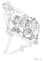
Fig. 2 is a side view showing the construction of an engine unit. -
Fig. 3 is a cross sectional view showing the construction of the engine unit. -
Fig. 4 is a side view showing the construction of an engine unit, a transmission shaft of which is arranged closer to a crank shaft than a clutch shaft is. -
Fig. 5 is a cross sectional view showing an engine unit described inWO2003/085278 A1 . -
Fig. 6 is a side view showing the engine unit described in PatentWO2003/085278 A1 . - In an embodiment of the invention, in order to make an engine unit compact, a transmission shaft (reduction shaft), which is ordinarily arranged between an axis of rotation of a crank shaft and an axis of rotation of a clutch shaft, is positively arranged in a position more distant from the crank shaft than from the clutch shaft whereby a lubricating oil scattering from the crank shaft is efficiently fed to the clutch shaft and a clutch mechanism. A specific construction of the embodiment will be described below in detail with reference to the drawings.
- In addition, the embodiment will be described citing an offroad type motorcycle 1 shown in
Fig. 1 as an example of a straddle-type vehicle, in which the invention is embodied. However, a straddle-type vehicle according to the invention is not limited to this. A straddle-type vehicle according to the invention may be a motorcycle of other types than the offroad type one. Specifically, a straddle-type vehicle according to the invention may be a motorcycle of a motorcycle type, scooter type, a so-called moped type, or the like. Also, a straddle-type vehicle according to the invention may be a straddle-type vehicle other than a motorcycle. A straddle-type vehicle according to the invention may be, for example, ATV (All Terrain Vehicle), etc. -
Fig. 1 is a side view showing a motorcycle 1 according to the embodiment. First, an outline construction of the motorcycle 1 will be described mainly with reference toFig. 1 . In addition, front and rear, and left and right directions in the following descriptions are ones as seen from a rider, or driver, seated on a seat 11. - The motorcycle 1 comprises a body frame 2 . The body frame 2 comprises a head pipe 3, a downtube 4 extending downward from the head pipe 3, and a
seat pillar 5 extending rearward from the head pipe 3. In addition,Fig. 2 shows only a part of the downtube 4. The head pipe 3 is connected at its lower end to a front wheel 7 through a front fork 6, etc. The body frame 2 journals a rear arm 8 extending rearward. A rear end of the rear arm 8 is connected to a rear wheel 9. Acover 10 is arranged above the body frame 2 to cover the body frame 2. The seat 11 is provided a little rearwardly of a center of thecover 10. - As viewed in side view, an
engine unit 12 supported by the downtube 4 and theseat pillar 5 is arranged between the downtube 4 and theseat pillar 5. As shown inFigs. 2 and3 , theengine unit 12 is composed integrally of anengine 13, a belt type continuously variable transmission (referred below to as "CVT (continuously variable transmission)" 14, acentrifugal clutch 40c, areduction mechanism 16, etc. Driving force generated in theengine unit 12 is transmitted to the rear wheel 9 through power transmission means (not shown) such as chain, belt, etc. In addition, while theengine 13 is described herein as four-stroke single cylinder engine, theengine 13 may be, for example, a two-stroke engine. Also, the engine may be a multi-cylinder engine. - The construction of the
engine unit 12 will now be described mainly with reference toFig. 3. Fig. 3 is a cross sectional view showing a part cut out along the cut line III-III inFig. 2 . - The
engine unit 12 comprises theengine 13, theCVT 14, the centrifugal clutch 40c, and thereduction mechanism 16 as a transmission mechanism.Fig. 3 omits a partial construction of thereduction mechanism 16 for the convenience of explanation. - The
engine 13 comprises a crankcase 17, a substantially cylindrical-shapedcylinder 18, and acylinder head 19. The crankcase 17 is composed of two case blocks including afirst case block 17a positioned on the left and asecond case block 17b positioned on the right. Thefirst case block 17a and thesecond case block 17b are arranged to butt against each other in a vehicle width direction. Thecylinder 18 is connected forwardly and upwardly obliquely to the crank case 17 (Also, seeFig. 1 ). Thecylinder head 19 is connected to a top end of thecylinder 18. - A
crank shaft 20 extending horizontally in the vehicle width direction is accommodated in thecrank case 17. Thecrank shaft 20 is supported on thefirst case block 17a and thesecond case block 17b withbearings crank shaft 20 comprises a crank-shaft body 20f and acrank pin 15. - A
piston 23 is inserted slidably into thecylinder 18. One end of a connectingrod 24 is connected to a side of thepiston 23 toward thecrank shaft 20. The other end of the connectingrod 24 is connected to the crank-shaft body 20f by acrank pin 15 arranged between aleft crank arm 20a and a right crank arm 20b of thecrank shaft 20. Thereby, thepiston 23 reciprocates in thecylinder 18 upon rotation of thecrank shaft 20. - Formed in the
cylinder head 19 are arecess 19a communicated to an internal space of thecylinder 18 and an intake port 19b and anexhaust port 19c (seeFig. 2 ), which communicate with therecess 19a. Also, as shown inFig. 3 , anignition plug 25 is inserted into and fixed to thecylinder head 19 so that an ignition part at a top end thereof is exposed into therecess 19a. - A cam chain chamber 26 is formed on the left in the
cylinder 18 to provide communication between an interior of thecrank case 17 and an interior of thecylinder head 19. Atiming chain 27 is arranged in the cam chain chamber 26. Thetiming chain 27 is wound round thecrank shaft 20 and acam shaft 28. Thereby, as thecrank shaft 20 rotates, thecam shaft 28 also rotates, so that an intake valve and an exhaust valve, which are not shown, are opened and closed. - A
generator case 30, in which agenerator 29 is accommodated, is mounted detachably to a left side of a front half of thefirst case block 17a. On the other hand, atransmission case 31, in which theCVT 14 is accommodated, is mounted to a right side of thesecond case block 17b. - A
clutch cover 32 is fixed detachably to thesecond case block 17b by abolt 33 on the right side of thesecond case block 17b rearwardly of thecrank shaft 20 in a manner to face thesecond case block 17b. According to the embodiment, thesecond case block 17b and theclutch cover 32 constitute a clutch case to compartment and form a clutch chamber 51, in which aclutch shaft 40 is accommodated. Theclutch shaft 40 extends rightward through theclutch cover 32 to be extended into thetransmission case 31 described later. Theclutch shaft 40 is arranged to overlap a connection 42 in a direction along anaxis 20e of rotation of the crank shaft 20 (seeFigs. 2 and3 ). That portion of theclutch shaft 40, which extends into thetransmission case 31, constitutes asecondary sheave shaft 38. - The
clutch shaft 40 comprises aclutch shaft body 40b and a wet and centrifugal type clutch 40c. The centrifugal type clutch 40c is mounted to theclutch shaft body 40b within the clutch chamber 51. The centrifugal type clutch 40c meshes with areduction shaft 16a as a transmission shaft of thereduction mechanism 16. Specifically, the centrifugal type clutch 40c comprises a clutch boss 40c1 and a clutch housing 40c2. The clutch housing 40c2 is connected to theclutch shaft body 40b. The clutch boss 40c1 is arranged in the clutch housing 40c2. The clutch boss 40c1 is rotatable relative to theclutch shaft body 40b. The clutch housing 40c2 and the clutch boss 40c1 separate from each other when theclutch shaft body 40b is low in speed of rotation. On the other hand, when theclutch shaft body 40b is high in speed of rotation, the clutch housing 40c2 and the clutch boss 40c1 are connected to each other and the clutch boss 40c1 rotates together with the clutch housing 40c2. The clutch boss 40c1 is connected to a gear mechanism 40c3. The gear mechanism 40c3 meshes with thereduction shaft 16a. Therefore, as the clutch boss 40cl rotates, the gear mechanism 40c3 and thereduction shaft 16a rotate. Thereby, torque of theclutch shaft body 40b is transmitted to thereduction mechanism 16 through the centrifugal type clutch 40c and further transmitted to the rear wheel 9 by power transmission means (not shown) such as chain, belt, etc. - According to the embodiment, the
reduction shaft 16a of thereduction mechanism 16 is arranged in a position more distant from thecrank shaft 20 than from theclutch shaft 40, that is, rearward as shown inFigs. 2 and3 . In other words, theclutch shaft body 40b, to which the wet centrifugal type clutch 40c is mounted, is arranged closer to thecrank shaft 20 than to thereduction shaft 16a. A construction is provided, in which any rotating shaft for prevention of oil supply to theclutch shaft 40 is not substantially existent between theaxis 20e of rotation of thecrank shaft 20 and anaxis 40a of rotation of theclutch shaft 40. In particular, according to the embodiment, any rotating shaft is not arranged between theaxis 20e of rotation of thecrank shaft 20 and theaxis 40a of rotation of theclutch shaft 40. - The
transmission case 31 is provided on the right of and independently of thecrank case 17. Specifically, thetransmission case 31 comprises an inner case 31a, which covers an inner side of theCVT 14 in the vehicle width direction, and an outer case 31b, which covers an outer side of theCVT 14 in the vehicle width direction. The inner case 31a is mounted to a right side of thecrank case 17. On the other hand, the outer case 31b is mounted to a right side of the inner case 31a and abelt chamber 34 is compartmented and formed by the outer case 31b and the inner case 31a. - A left end of the
crank shaft 20 extends through thefirst case block 17a to reach an interior of thegenerator case 30. Thegenerator 29 is mounted to the left end of thecrank shaft 20. Thegenerator 29 comprises astator 29a and arotor 29b arranged in opposition to thestator 29a. Thestator 29a is fixed to thegenerator case 30 not to enable rotation and displacement. On the other hand, therotor 29b is fixed non-rotatably to asleeve 35, which rotates together with thecrank shaft 20. Thereby, as thecrank shaft 20 rotates, therotor 29b rotates relative to thestator 29a to generate electric power. - The
CVT 14 is accommodated in thebelt chamber 34. TheCVT 14 comprises a primary sheave 36 and asecondary sheave 37 arranged rearwardly of the primary sheave 36. Thecrank shaft 20 extends through thesecond case block 17b and the inner case 31a to extend to thebelt chamber 34 and a right portion thereof (strictly, a portion on the right of the bearing 22) constitutes aprimary sheave shaft 20c. The primary sheave 36 is journaled by theprimary sheave shaft 20c. Thereby, the primary sheave 36 rotates as thecrank shaft 20 rotates. - On the other hand, the
secondary sheave shaft 38 made integral with theclutch shaft 40 as described above is arranged on a rear half of thetransmission case 31. Thesecondary sheave shaft 38 is mounted to theclutch cover 32 with abearing 39 therebetween. Thesecondary sheave 37 is journaled by thesecondary sheave shaft 38 withinbelt chamber 34. - A
belt 41 is wound round thesecondary sheave 37 and the primary sheave 36. Thebelt 41 may be composed of, for example, a resin block V-belt. Therefore, when the primary sheave 36 rotates together with thecrank shaft 20, torque thereof is transmitted to thesecondary sheave 37 through thebelt 41 and thesecondary sheave shaft 38 rotates together with thesecondary sheave 37. Thereby, theclutch shaft 40 made integral with thesecondary sheave shaft 38 rotates and torque thereof is transmitted to the rear wheel 9 through thereduction mechanism 16. - Subsequently, a construction, in which a lubricating oil is supplied to the
clutch shaft 40, according to the embodiment will be described with reference toFigs. 2 and3 . As shown inFig. 2 , anoil reservoir portion 17d is provided on a bottom of thecrank case 17 to store the lubricating oil. The lubricating oil stored there is supplied to the connection 42 of thecrank shaft 20 and the connectingrod 24 by anoil pump 60, which is arranged as lubricating oil supply means on theoil reservoir portion 17d in thecrank case 17. Specifically, the lubricating oil drawn by theoil pump 60 is led to one or a plurality ofoil supply passages 20d, which are substantially circular in shape as viewed in plan view and opened to a left end surface of thecrank shaft 20, to be supplied to the connection 42 via the oil supply passage orpassages 20d. - The lubricating oil as supplied scatters from the connection 42 as the
crank shaft 20 rotates. Formed on thesecond case block 17b is anoil supply hole 17c to lead a lubricating oil, which scatters as thecrank shaft 20 rotates, into the clutch chamber 51 to supply the same to theclutch shaft 40. Specifically, as shown inFig. 2 , theoil supply hole 17c is formed on thesecond case block 17b so that a tangent line L1 tangent to both acircular track 15a of thecrank pin 15 and an outer ring of theoil supply hole 17c is positioned above a lower end A of theclutch shaft body 40b as viewed in side view. In addition, the tangent line L1 is more specifically a tangent line, which is tangent to a lower portion of thecircular track 15a of thecrank pin 15 and an upper portion of theoil supply hole 17c and passes between theoil supply hole 17c and thecircular track 15a to extend rearward and obliquely upward. Further, theoil supply hole 17c is formed on thesecond case block 17b so that at least a portion thereof is positioned above a plane C including the axis of rotation of thecrank shaft 20 and the axis of rotation of theclutch shaft 40. For example, theoil supply hole 17c is formed on thesecond case block 17b so that a center of theoil supply hole 17c is positioned on the plane C. Thecrank shaft 20 and theclutch shaft 40 are arranged so that portions thereof face each other with theoil supply hole 17c therebetween. - The lubricating oil introduced into the clutch chamber 51 from the
oil supply hole 17c is supplied to theclutch shaft 40 and thereafter returns again to theoil reservoir portion 17d from anoil discharge hole 17e provided downwardly and a little rearwardly of thesecond case block 17b. - As described above, according to the embodiment, as the
crank shaft 20 rotates, a lubricating oil is supplied to theclutch shaft 40. Therefore, when thecrank shaft 20 and theclutch shaft 40 are increased in speed of rotation per unit time, the lubricating oil supplied to theclutch shaft 40 is correspondingly increased in quantity. Accordingly, seizure of the centrifugal type clutch 40c is surely suppressed even when thecrank shaft 20 and theclutch shaft 40 are high in speed of rotation per unit time and the centrifugal type clutch 40c is relatively liable to undergo seizure. - For example, with the construction shown in
Fig. 4 , areduction shaft 216a inhibits a lubricating oil introduced into aclutch chamber 251 from being supplied to aclutch shaft 240. Specifically, as shown inFig. 4 , since thereduction shaft 216a is arranged closer to a crankshaft 220 than to theclutch shaft 240, a major part of the lubricating oil introduced into the clutch chamber 51 from theoil supply hole 17c strikes against thereduction shaft 216a. With the construction shown inFig. 4 , a part of the lubricating oil striking against thereduction shaft 216a to scatter is only supplied to theclutch shaft 240 and so it is difficult to efficiently supply a lubricating oil to theclutch shaft 240. Therefore, it becomes necessary to increase a lubricating oil supplied to the crankshaft 220 in quantity per unit time and to make theoil supply hole 17c large in size. - In contrast, the reduction shaft (transmission shaft) 16a normally arranged between the
axis 20e of rotation of thecrank shaft 20 and theaxis 40a of rotation of theclutch shaft 40 as shown inFig. 2 is arranged rearwardly of theclutch shaft 40 according to the embodiment. That is, theclutch shaft body 40b is arranged closer to thecrank shaft 20 than to thereduction shaft 16a. Accordingly, the lubricating oil supplied from the connection 42 is efficiently supplied to theclutch shaft 40 without being obstructed by thereduction shaft 16a, etc. In particular, according to the embodiment, a construction is realized, in which any rotating shaft is not existent between theaxis 20e of rotation of thecrank shaft 20 and theaxis 40a of rotation of theclutch shaft 40, and so further efficient supply of the lubricating oil to theclutch shaft 40 is realized. - Also, as far as the lubricating oil scatters mainly in a direction, in which the
crank shaft 20 is tangent to thecircular track 15a of thecrank pin 15, owing to rotation of thecrank shaft 20, theoil supply hole 17c is arranged so that the tangent line L1 tangent to both thecircular track 15a of the crank pin and the outer ring of theoil supply hole 17c is positioned above the lower end A of theclutch shaft 40 as viewed in side view. Further, a tangent line L2, which is tangent to thecircular track 15a and passes through a center of theoil supply hole 17c as viewed in side view, is arranged so as to be positioned above the lower end A of theclutch shaft 40. Therefore, supply of a lubricating oil to theclutch shaft 40 can be improved in efficiency. Further, from the viewpoint of an improvement in efficiency of supply, theoil supply hole 17c is preferably formed so that the tangent line L1 (L2) is positioned above theaxis 40a of rotation of theclutch shaft 40 and further above an upper end of theclutch shaft body 40b. In particular, preferably, at least a portion of theoil supply hole 17c is preferably positioned above the plane C including theaxis 20e of rotation of thecrank shaft 20 and theaxis 40a of rotation of theclutch shaft 40, and at least portions of thecrank shaft 20 and theclutch shaft 40 face each other. - As described above, according to the embodiment, since efficient supply of a lubricating oil to the
clutch shaft 40 is realized, seizure of the centrifugal type clutch 40c is effectively suppressed. Also, it is possible to make theoil supply hole 17c relatively small in size. Further, a large oil supply capacity per unit time is not so much demanded of theoil pump 60 and so it is possible to make theoil pump 60 and hence theengine unit 12 small in size and light in weight. - Also, according to the embodiment, as shown in
Fig. 2 , the plane C extends rearwardly upward. That is, thecrank case 17 is arranged to be directed rearwardly upward. Thesecondary sheave shaft 38 is arranged in a relatively high position. Therefore, thesecondary sheave shaft 38 is relatively distant from an oil surface of a lubricating oil stored in theoil reservoir portion 17d. Accordingly, even when the motorcycle 1 undergoes vibrations and fluctuation, the lubricating oil stored in theoil reservoir portion 17d scatters, and the oil surface of the lubricating oil fluctuates, the lubricating oil stored in theoil reservoir portion 17d is inhibited from being supplied in large quantity directly to theclutch shaft 40. Consequently, the lubricating oil is inhibited from being excessively supplied to the centrifugal type clutch 40c. Accordingly, it is possible to suppress loss in energy transmission to the centrifugal type clutch 40c. Also, it is possible to suppress a decrease in speed of rotation of the centrifugal type clutch 40c. Further, it is possible to inhibit the lubricating oil from being increased in temperature. Consequently, it is possible to inhibit the lubricating oil from being decreased in lubrication. In addition, the construction is especially effective in a straddle-type vehicle, which runs on a relatively irregular land such as dirt course, etc., like the offroad type motorcycle according to the embodiment. - While the embodiment has taken the case of the
engine unit 12 provided with the centrifugal type clutch 40c and the motorcycle 1 to explain an example of preferred embodiments of the invention, the clutch may be other than a centrifugal type one as far as it is of a wet type. - The embodiment has explained an example, in which the
engine 13 is arranged so that a direction, in which thecylinder 18 extends, is relatively close to a vertical direction. However, an arrangement of theengine 13 is not especially limited in the invention. Specifically, theengine 13 is preferably applied also to a straddle-type vehicle arranged so that a direction, in which thecylinder 18 extends, is relatively close to a horizontal direction. - According to the embodiment, the
clutch shaft 40 is arranged so as to overlap the connection 42 in a direction along theaxis 20e of rotation of the crank shaft 20 (seeFigs. 2 and3 ). Since the lubricating oil from the connection 42 scatters radially, however, it is not necessarily required that theclutch shaft 40 be arranged so as to overlap the connection 42 in the direction along theaxis 20e of rotation of thecrank shaft 20. It suffices that at least a portion of theclutch shaft 40 be arranged to be positioned in a region, in which the lubricating oil from the connection 42 scatters. - The
oil supply hole 17c is not especially limited in shape. Theoil supply hole 17c may be, for example, elliptical, rectangular, and polygonal in shape. Also, a plurality of theoil supply holes 17c may be formed. - According to the embodiment, the lubricating oil scattering from the connection 42 is led directly into the clutch chamber 51 to be supplied to the
clutch shaft 40. However, a guide member or the like for changing a direction, in which a lubricating oil scatters, may be arranged in the vicinity of theoil supply holes 17c to cause the lubricating oil, which strikes against the guide member, to be supplied to theclutch shaft 40. However, a belt type continuously variable transmission having a construction, in which a lubricating oil having scattered is once stored and the lubricating oil thus stored is led to theclutch shaft 40 with the use of a pump or the like, does not belong to the invention. - The invention is useful for a straddle-type vehicle provided with a belt type continuously variable transmission. In particular, the invention is useful for a straddle-type vehicle provided with a belt type continuously variable transmission and having a relatively large displacement.
-
- 1: motorcycle
- 2: body frame
- 3: head pipe
- 4: downtube
- 5: seat pillar
- 6: front fork
- 7: front wheel
- 8: rear arm
- 9: rear wheel
- 12: engine unit
- 13: engine
- 14: belt type continuously variable transmission (CVT)
- 15: crank pin
- 16: reduction mechanism
- 16a: reduction shaft
- 17: crank case
- 17c: oil supply hole
- 17d: oil reservoir portion
- 17e: oil discharge hole
- 20: crank shaft
- 20a: left crank arm
- 20b: right crank arm
- 20d: oil supply passage
- 20e: axis of rotation of crank shaft
- 20f: crank shaft body
- 23: piston
- 24: connecting rod
- 32: clutch cover
- 40: clutch shaft
- 40a: axis of rotation of clutch shaft
- 40b: clutch shaft body
- 40c: centrifugal type clutch
- 51: clutch chamber
- 60: oil pump
Claims (9)
- An engine unit comprising
a crank shaft,
a connecting rod connected to the crank shaft,
a lubricating-oil supply mechanism, which supplies a lubricating oil to a connection of the crank shaft and the connecting rod,
a clutch shaft having a clutch shaft body arranged in parallel to the crank shaft and a wet type clutch mechanism mounted to the clutch shaft body, and
a transmission mechanism arranged in parallel to the crank shaft and having a transmission shaft, which meshes with the clutch mechanism,
wherein the clutch shaft body is arranged closer to the crank shaft than to the transmission shaft and constructed so that a lubricating oil supplied to the connection to scatter is led to the clutch shaft. - The engine unit according to claim 1, wherein the clutch shaft is arranged in a region, in which the lubricating oil supplied to the connection scatters upon rotation of the crank shaft.
- The engine unit according to claim 1 or claim 2, further comprising a clutch case, which compartments and forms a clutch chamber, in which a clutch shaft is accommodated, and separates the clutch shaft from the crank shaft, wherein the clutch case is formed with an oil supply hole, through which the lubricating oil from the connection is led into the clutch chamber.
- The engine unit according to claim 3, wherein the crank shaft comprises a crank-shaft body and a crank pin for connection of the crank-shaft body and the connecting rod, and the oil supply hole is arranged so that a tangent line contacting with a lower portion of a circular track of the crank pin and an upper portion of the oil supply hole and passing between the oil supply hole and the circular track is positioned above a lower end of the clutch shaft as viewed in side view.
- The engine unit according to claim 3 or claim 4, wherein the oil supply hole is arranged so that at least a portion thereof is positioned above a plane including an axis of rotation of the crank shaft and an axis of rotation of the clutch shaft.
- The engine unit according to any preceding claim, wherein the connection and the clutch shaft overlap each other in a direction along an axis of rotation of the crank shaft.
- The engine unit according to any preceding claim, wherein any rotating shaft is not arranged between an axis of rotation of the crank shaft and an axis of rotation of the clutch shaft.
- The engine unit, according to any preceding claim, provided with a belt type continuously variable transmission, which comprises a primary sheave mounted to the crank shaft to rotate with the crank shaft, a secondary sheave mounted to the clutch shaft to rotate with the clutch shaft, and a belt wound round the secondary sheave and the primary sheave.
- A straddle-type vehicle comprising the engine unit according to any preceding claim.
Applications Claiming Priority (1)
| Application Number | Priority Date | Filing Date | Title |
|---|---|---|---|
| JP2007016492A JP4907368B2 (en) | 2007-01-26 | 2007-01-26 | Engine unit and saddle riding type vehicle equipped with the same |
Publications (3)
| Publication Number | Publication Date |
|---|---|
| EP1950460A2 true EP1950460A2 (en) | 2008-07-30 |
| EP1950460A3 EP1950460A3 (en) | 2014-01-22 |
| EP1950460B1 EP1950460B1 (en) | 2014-12-24 |
Family
ID=39304854
Family Applications (1)
| Application Number | Title | Priority Date | Filing Date |
|---|---|---|---|
| EP08250286.5A Active EP1950460B1 (en) | 2007-01-26 | 2008-01-23 | Engine unit and straddle-type vehicle provided with the same |
Country Status (3)
| Country | Link |
|---|---|
| US (1) | US7721700B2 (en) |
| EP (1) | EP1950460B1 (en) |
| JP (1) | JP4907368B2 (en) |
Families Citing this family (4)
| Publication number | Priority date | Publication date | Assignee | Title |
|---|---|---|---|---|
| JP4939190B2 (en) * | 2006-11-30 | 2012-05-23 | 本田技研工業株式会社 | Power unit for small vehicles |
| JP5809829B2 (en) * | 2011-03-31 | 2015-11-11 | 本田技研工業株式会社 | Engine lubrication structure |
| CN105888876A (en) * | 2016-06-14 | 2016-08-24 | 重庆隆鑫发动机有限公司 | Crankcase cover and clutch side surface cooling and lubricating structure based on crankcase cover |
| JP6899858B2 (en) * | 2019-03-05 | 2021-07-07 | 本田技研工業株式会社 | Internal combustion engine |
Citations (3)
| Publication number | Priority date | Publication date | Assignee | Title |
|---|---|---|---|---|
| JPH0665894B2 (en) | 1983-10-22 | 1994-08-24 | ヤマハ発動機株式会社 | Friction clutch |
| JP2001003723A (en) | 1999-06-17 | 2001-01-09 | Yamaha Motor Co Ltd | Motorcycle engine |
| WO2003085278A1 (en) | 2002-04-08 | 2003-10-16 | Yamaha Hatsudoki Kabushiki Kaisha | Clutch mechanism lubricating structure of engine |
Family Cites Families (4)
| Publication number | Priority date | Publication date | Assignee | Title |
|---|---|---|---|---|
| JP3099148B2 (en) | 1992-08-14 | 2000-10-16 | 星光化学工業株式会社 | Processing agent for paper |
| CN101220770A (en) * | 2002-04-08 | 2008-07-16 | 雅马哈发动机株式会社 | Engine |
| ES2386541T3 (en) * | 2002-04-08 | 2012-08-22 | Yamaha Hatsudoki Kabushiki Kaisha | Engine |
| JP2006342815A (en) * | 2003-06-16 | 2006-12-21 | Yamaha Motor Co Ltd | V belt type continuously variable transmission engine |
-
2007
- 2007-01-26 JP JP2007016492A patent/JP4907368B2/en active Active
-
2008
- 2008-01-23 EP EP08250286.5A patent/EP1950460B1/en active Active
- 2008-01-24 US US12/019,588 patent/US7721700B2/en active Active
Patent Citations (3)
| Publication number | Priority date | Publication date | Assignee | Title |
|---|---|---|---|---|
| JPH0665894B2 (en) | 1983-10-22 | 1994-08-24 | ヤマハ発動機株式会社 | Friction clutch |
| JP2001003723A (en) | 1999-06-17 | 2001-01-09 | Yamaha Motor Co Ltd | Motorcycle engine |
| WO2003085278A1 (en) | 2002-04-08 | 2003-10-16 | Yamaha Hatsudoki Kabushiki Kaisha | Clutch mechanism lubricating structure of engine |
Also Published As
| Publication number | Publication date |
|---|---|
| EP1950460A3 (en) | 2014-01-22 |
| US20080178834A1 (en) | 2008-07-31 |
| US7721700B2 (en) | 2010-05-25 |
| EP1950460B1 (en) | 2014-12-24 |
| JP2008184909A (en) | 2008-08-14 |
| JP4907368B2 (en) | 2012-03-28 |
Similar Documents
| Publication | Publication Date | Title |
|---|---|---|
| EP1930562B1 (en) | Straddle-type vehicle | |
| JP4992061B2 (en) | engine | |
| US8038557B2 (en) | Power unit and saddle-ride type vehicle provided with the power unit | |
| US6557516B2 (en) | Engine unit for a vehicle | |
| EP1950460B1 (en) | Engine unit and straddle-type vehicle provided with the same | |
| JP2021008215A (en) | Hybrid vehicle | |
| EP1396420B1 (en) | Saddle ride type vehicle torque damping device | |
| US8893682B2 (en) | Multi-cylinder internal combustion engine | |
| JP3993170B2 (en) | Engine clutch mechanism lubrication structure | |
| JP2011163429A (en) | Breather structure of power unit | |
| JP4140263B2 (en) | Motorcycle power unit | |
| JP2008308990A (en) | Engine, vehicle mounted lid and engine equipped vehicle | |
| JP4627067B2 (en) | Motorcycle | |
| JP2021008217A (en) | Saddle-riding vehicle | |
| JP4181051B2 (en) | engine | |
| JP2007024007A (en) | Lubricating device for internal combustion engine | |
| JP6102468B2 (en) | Engine breather structure | |
| JP6205974B2 (en) | Engine oil strainer structure | |
| JP4031683B2 (en) | Dry sump 4-cycle engine | |
| CN101813045B (en) | An distribution structure of engine starting motor | |
| JP4535911B2 (en) | Lubrication structure of internal combustion engine | |
| JP2006283623A (en) | Lubrication structure of internal combustion engine | |
| JP2008075713A (en) | Vehicle engine | |
| JP2726452B2 (en) | Engine cell motor arrangement structure | |
| JP2005291052A (en) | Lubrication structure of internal combustion engine |
Legal Events
| Date | Code | Title | Description |
|---|---|---|---|
| PUAI | Public reference made under article 153(3) epc to a published international application that has entered the european phase |
Free format text: ORIGINAL CODE: 0009012 |
|
| AK | Designated contracting states |
Kind code of ref document: A2 Designated state(s): AT BE BG CH CY CZ DE DK EE ES FI FR GB GR HR HU IE IS IT LI LT LU LV MC MT NL NO PL PT RO SE SI SK TR |
|
| AX | Request for extension of the european patent |
Extension state: AL BA MK RS |
|
| PUAL | Search report despatched |
Free format text: ORIGINAL CODE: 0009013 |
|
| AK | Designated contracting states |
Kind code of ref document: A3 Designated state(s): AT BE BG CH CY CZ DE DK EE ES FI FR GB GR HR HU IE IS IT LI LT LU LV MC MT NL NO PL PT RO SE SI SK TR |
|
| AX | Request for extension of the european patent |
Extension state: AL BA MK RS |
|
| RIC1 | Information provided on ipc code assigned before grant |
Ipc: F01M 1/02 20060101ALN20131218BHEP Ipc: F16D 43/10 20060101ALN20131218BHEP Ipc: F16H 57/04 20100101AFI20131218BHEP Ipc: F16D 25/12 20060101ALN20131218BHEP |
|
| 17P | Request for examination filed |
Effective date: 20140210 |
|
| RBV | Designated contracting states (corrected) |
Designated state(s): AT BE BG CH CY CZ DE DK EE ES FI FR GB GR HR HU IE IS IT LI LT LU LV MC MT NL NO PL PT RO SE SI SK TR |
|
| GRAP | Despatch of communication of intention to grant a patent |
Free format text: ORIGINAL CODE: EPIDOSNIGR1 |
|
| RIC1 | Information provided on ipc code assigned before grant |
Ipc: F01M 1/02 20060101ALN20140630BHEP Ipc: F16D 25/12 20060101ALN20140630BHEP Ipc: F16D 43/10 20060101ALN20140630BHEP Ipc: F16H 57/04 20100101AFI20140630BHEP |
|
| INTG | Intention to grant announced |
Effective date: 20140714 |
|
| AKX | Designation fees paid |
Designated state(s): AT BE BG CH CY CZ DE DK EE ES FI FR GB GR HR HU IE IS IT LI LT LU LV MC MT NL NO PL PT RO SE SI SK TR |
|
| GRAS | Grant fee paid |
Free format text: ORIGINAL CODE: EPIDOSNIGR3 |
|
| GRAA | (expected) grant |
Free format text: ORIGINAL CODE: 0009210 |
|
| AK | Designated contracting states |
Kind code of ref document: B1 Designated state(s): AT BE BG CH CY CZ DE DK EE ES FI FR GB GR HR HU IE IS IT LI LT LU LV MC MT NL NO PL PT RO SE SI SK TR |
|
| REG | Reference to a national code |
Ref country code: GB Ref legal event code: FG4D |
|
| REG | Reference to a national code |
Ref country code: CH Ref legal event code: EP |
|
| REG | Reference to a national code |
Ref country code: IE Ref legal event code: FG4D |
|
| REG | Reference to a national code |
Ref country code: AT Ref legal event code: REF Ref document number: 703330 Country of ref document: AT Kind code of ref document: T Effective date: 20150115 |
|
| REG | Reference to a national code |
Ref country code: DE Ref legal event code: R096 Ref document number: 602008035989 Country of ref document: DE Effective date: 20150219 |
|
| REG | Reference to a national code |
Ref country code: NL Ref legal event code: VDEP Effective date: 20141224 |
|
| PG25 | Lapsed in a contracting state [announced via postgrant information from national office to epo] |
Ref country code: FI Free format text: LAPSE BECAUSE OF FAILURE TO SUBMIT A TRANSLATION OF THE DESCRIPTION OR TO PAY THE FEE WITHIN THE PRESCRIBED TIME-LIMIT Effective date: 20141224 Ref country code: NO Free format text: LAPSE BECAUSE OF FAILURE TO SUBMIT A TRANSLATION OF THE DESCRIPTION OR TO PAY THE FEE WITHIN THE PRESCRIBED TIME-LIMIT Effective date: 20150324 Ref country code: LT Free format text: LAPSE BECAUSE OF FAILURE TO SUBMIT A TRANSLATION OF THE DESCRIPTION OR TO PAY THE FEE WITHIN THE PRESCRIBED TIME-LIMIT Effective date: 20141224 |
|
| REG | Reference to a national code |
Ref country code: LT Ref legal event code: MG4D |
|
| PG25 | Lapsed in a contracting state [announced via postgrant information from national office to epo] |
Ref country code: HR Free format text: LAPSE BECAUSE OF FAILURE TO SUBMIT A TRANSLATION OF THE DESCRIPTION OR TO PAY THE FEE WITHIN THE PRESCRIBED TIME-LIMIT Effective date: 20141224 Ref country code: SE Free format text: LAPSE BECAUSE OF FAILURE TO SUBMIT A TRANSLATION OF THE DESCRIPTION OR TO PAY THE FEE WITHIN THE PRESCRIBED TIME-LIMIT Effective date: 20141224 Ref country code: LV Free format text: LAPSE BECAUSE OF FAILURE TO SUBMIT A TRANSLATION OF THE DESCRIPTION OR TO PAY THE FEE WITHIN THE PRESCRIBED TIME-LIMIT Effective date: 20141224 Ref country code: GR Free format text: LAPSE BECAUSE OF FAILURE TO SUBMIT A TRANSLATION OF THE DESCRIPTION OR TO PAY THE FEE WITHIN THE PRESCRIBED TIME-LIMIT Effective date: 20150325 |
|
| REG | Reference to a national code |
Ref country code: AT Ref legal event code: MK05 Ref document number: 703330 Country of ref document: AT Kind code of ref document: T Effective date: 20141224 |
|
| PG25 | Lapsed in a contracting state [announced via postgrant information from national office to epo] |
Ref country code: NL Free format text: LAPSE BECAUSE OF FAILURE TO SUBMIT A TRANSLATION OF THE DESCRIPTION OR TO PAY THE FEE WITHIN THE PRESCRIBED TIME-LIMIT Effective date: 20141224 |
|
| PG25 | Lapsed in a contracting state [announced via postgrant information from national office to epo] |
Ref country code: RO Free format text: LAPSE BECAUSE OF FAILURE TO SUBMIT A TRANSLATION OF THE DESCRIPTION OR TO PAY THE FEE WITHIN THE PRESCRIBED TIME-LIMIT Effective date: 20141224 Ref country code: CZ Free format text: LAPSE BECAUSE OF FAILURE TO SUBMIT A TRANSLATION OF THE DESCRIPTION OR TO PAY THE FEE WITHIN THE PRESCRIBED TIME-LIMIT Effective date: 20141224 Ref country code: EE Free format text: LAPSE BECAUSE OF FAILURE TO SUBMIT A TRANSLATION OF THE DESCRIPTION OR TO PAY THE FEE WITHIN THE PRESCRIBED TIME-LIMIT Effective date: 20141224 Ref country code: ES Free format text: LAPSE BECAUSE OF FAILURE TO SUBMIT A TRANSLATION OF THE DESCRIPTION OR TO PAY THE FEE WITHIN THE PRESCRIBED TIME-LIMIT Effective date: 20141224 Ref country code: SK Free format text: LAPSE BECAUSE OF FAILURE TO SUBMIT A TRANSLATION OF THE DESCRIPTION OR TO PAY THE FEE WITHIN THE PRESCRIBED TIME-LIMIT Effective date: 20141224 |
|
| REG | Reference to a national code |
Ref country code: CH Ref legal event code: PL |
|
| PG25 | Lapsed in a contracting state [announced via postgrant information from national office to epo] |
Ref country code: LU Free format text: LAPSE BECAUSE OF FAILURE TO SUBMIT A TRANSLATION OF THE DESCRIPTION OR TO PAY THE FEE WITHIN THE PRESCRIBED TIME-LIMIT Effective date: 20150123 Ref country code: AT Free format text: LAPSE BECAUSE OF FAILURE TO SUBMIT A TRANSLATION OF THE DESCRIPTION OR TO PAY THE FEE WITHIN THE PRESCRIBED TIME-LIMIT Effective date: 20141224 Ref country code: PL Free format text: LAPSE BECAUSE OF FAILURE TO SUBMIT A TRANSLATION OF THE DESCRIPTION OR TO PAY THE FEE WITHIN THE PRESCRIBED TIME-LIMIT Effective date: 20141224 Ref country code: IS Free format text: LAPSE BECAUSE OF FAILURE TO SUBMIT A TRANSLATION OF THE DESCRIPTION OR TO PAY THE FEE WITHIN THE PRESCRIBED TIME-LIMIT Effective date: 20150424 |
|
| REG | Reference to a national code |
Ref country code: DE Ref legal event code: R097 Ref document number: 602008035989 Country of ref document: DE |
|
| PG25 | Lapsed in a contracting state [announced via postgrant information from national office to epo] |
Ref country code: MC Free format text: LAPSE BECAUSE OF FAILURE TO SUBMIT A TRANSLATION OF THE DESCRIPTION OR TO PAY THE FEE WITHIN THE PRESCRIBED TIME-LIMIT Effective date: 20141224 |
|
| PG25 | Lapsed in a contracting state [announced via postgrant information from national office to epo] |
Ref country code: CH Free format text: LAPSE BECAUSE OF NON-PAYMENT OF DUE FEES Effective date: 20150131 Ref country code: LI Free format text: LAPSE BECAUSE OF NON-PAYMENT OF DUE FEES Effective date: 20150131 Ref country code: DK Free format text: LAPSE BECAUSE OF FAILURE TO SUBMIT A TRANSLATION OF THE DESCRIPTION OR TO PAY THE FEE WITHIN THE PRESCRIBED TIME-LIMIT Effective date: 20141224 |
|
| PLBE | No opposition filed within time limit |
Free format text: ORIGINAL CODE: 0009261 |
|
| STAA | Information on the status of an ep patent application or granted ep patent |
Free format text: STATUS: NO OPPOSITION FILED WITHIN TIME LIMIT |
|
| REG | Reference to a national code |
Ref country code: IE Ref legal event code: MM4A |
|
| 26N | No opposition filed |
Effective date: 20150925 |
|
| PG25 | Lapsed in a contracting state [announced via postgrant information from national office to epo] |
Ref country code: IT Free format text: LAPSE BECAUSE OF FAILURE TO SUBMIT A TRANSLATION OF THE DESCRIPTION OR TO PAY THE FEE WITHIN THE PRESCRIBED TIME-LIMIT Effective date: 20141224 |
|
| REG | Reference to a national code |
Ref country code: FR Ref legal event code: PLFP Year of fee payment: 9 |
|
| PG25 | Lapsed in a contracting state [announced via postgrant information from national office to epo] |
Ref country code: IE Free format text: LAPSE BECAUSE OF NON-PAYMENT OF DUE FEES Effective date: 20150123 |
|
| PG25 | Lapsed in a contracting state [announced via postgrant information from national office to epo] |
Ref country code: SI Free format text: LAPSE BECAUSE OF FAILURE TO SUBMIT A TRANSLATION OF THE DESCRIPTION OR TO PAY THE FEE WITHIN THE PRESCRIBED TIME-LIMIT Effective date: 20141224 |
|
| PG25 | Lapsed in a contracting state [announced via postgrant information from national office to epo] |
Ref country code: BE Free format text: LAPSE BECAUSE OF FAILURE TO SUBMIT A TRANSLATION OF THE DESCRIPTION OR TO PAY THE FEE WITHIN THE PRESCRIBED TIME-LIMIT Effective date: 20141224 |
|
| PG25 | Lapsed in a contracting state [announced via postgrant information from national office to epo] |
Ref country code: MT Free format text: LAPSE BECAUSE OF FAILURE TO SUBMIT A TRANSLATION OF THE DESCRIPTION OR TO PAY THE FEE WITHIN THE PRESCRIBED TIME-LIMIT Effective date: 20141224 |
|
| REG | Reference to a national code |
Ref country code: FR Ref legal event code: PLFP Year of fee payment: 10 |
|
| PG25 | Lapsed in a contracting state [announced via postgrant information from national office to epo] |
Ref country code: BG Free format text: LAPSE BECAUSE OF FAILURE TO SUBMIT A TRANSLATION OF THE DESCRIPTION OR TO PAY THE FEE WITHIN THE PRESCRIBED TIME-LIMIT Effective date: 20141224 Ref country code: HU Free format text: LAPSE BECAUSE OF FAILURE TO SUBMIT A TRANSLATION OF THE DESCRIPTION OR TO PAY THE FEE WITHIN THE PRESCRIBED TIME-LIMIT; INVALID AB INITIO Effective date: 20080123 |
|
| PG25 | Lapsed in a contracting state [announced via postgrant information from national office to epo] |
Ref country code: CY Free format text: LAPSE BECAUSE OF FAILURE TO SUBMIT A TRANSLATION OF THE DESCRIPTION OR TO PAY THE FEE WITHIN THE PRESCRIBED TIME-LIMIT Effective date: 20141224 |
|
| PG25 | Lapsed in a contracting state [announced via postgrant information from national office to epo] |
Ref country code: PT Free format text: LAPSE BECAUSE OF FAILURE TO SUBMIT A TRANSLATION OF THE DESCRIPTION OR TO PAY THE FEE WITHIN THE PRESCRIBED TIME-LIMIT Effective date: 20150424 |
|
| PG25 | Lapsed in a contracting state [announced via postgrant information from national office to epo] |
Ref country code: TR Free format text: LAPSE BECAUSE OF FAILURE TO SUBMIT A TRANSLATION OF THE DESCRIPTION OR TO PAY THE FEE WITHIN THE PRESCRIBED TIME-LIMIT Effective date: 20141224 |
|
| REG | Reference to a national code |
Ref country code: FR Ref legal event code: PLFP Year of fee payment: 11 |
|
| P01 | Opt-out of the competence of the unified patent court (upc) registered |
Effective date: 20230527 |
|
| PGFP | Annual fee paid to national office [announced via postgrant information from national office to epo] |
Ref country code: GB Payment date: 20260123 Year of fee payment: 19 |
|
| PGFP | Annual fee paid to national office [announced via postgrant information from national office to epo] |
Ref country code: DE Payment date: 20260121 Year of fee payment: 19 |
|
| PGFP | Annual fee paid to national office [announced via postgrant information from national office to epo] |
Ref country code: FR Payment date: 20260123 Year of fee payment: 19 |