EP1950459A2 - Straddle-type vehicle with belt type continuously variable transmission having resin-block-type belt - Google Patents
Straddle-type vehicle with belt type continuously variable transmission having resin-block-type belt Download PDFInfo
- Publication number
- EP1950459A2 EP1950459A2 EP08250285A EP08250285A EP1950459A2 EP 1950459 A2 EP1950459 A2 EP 1950459A2 EP 08250285 A EP08250285 A EP 08250285A EP 08250285 A EP08250285 A EP 08250285A EP 1950459 A2 EP1950459 A2 EP 1950459A2
- Authority
- EP
- European Patent Office
- Prior art keywords
- casing
- air
- belt
- straddle
- flow path
- Prior art date
- Legal status (The legal status is an assumption and is not a legal conclusion. Google has not performed a legal analysis and makes no representation as to the accuracy of the status listed.)
- Granted
Links
Images





Classifications
-
- B—PERFORMING OPERATIONS; TRANSPORTING
- B62—LAND VEHICLES FOR TRAVELLING OTHERWISE THAN ON RAILS
- B62K—CYCLES; CYCLE FRAMES; CYCLE STEERING DEVICES; RIDER-OPERATED TERMINAL CONTROLS SPECIALLY ADAPTED FOR CYCLES; CYCLE AXLE SUSPENSIONS; CYCLE SIDECARS, FORECARS, OR THE LIKE
- B62K11/00—Motorcycles, engine-assisted cycles or motor scooters with one or two wheels
- B62K11/02—Frames
- B62K11/04—Frames characterised by the engine being between front and rear wheels
-
- F—MECHANICAL ENGINEERING; LIGHTING; HEATING; WEAPONS; BLASTING
- F16—ENGINEERING ELEMENTS AND UNITS; GENERAL MEASURES FOR PRODUCING AND MAINTAINING EFFECTIVE FUNCTIONING OF MACHINES OR INSTALLATIONS; THERMAL INSULATION IN GENERAL
- F16H—GEARING
- F16H57/00—General details of gearing
- F16H57/02—Gearboxes; Mounting gearing therein
- F16H57/035—Gearboxes for gearing with endless flexible members
-
- F—MECHANICAL ENGINEERING; LIGHTING; HEATING; WEAPONS; BLASTING
- F16—ENGINEERING ELEMENTS AND UNITS; GENERAL MEASURES FOR PRODUCING AND MAINTAINING EFFECTIVE FUNCTIONING OF MACHINES OR INSTALLATIONS; THERMAL INSULATION IN GENERAL
- F16H—GEARING
- F16H57/00—General details of gearing
- F16H57/04—Features relating to lubrication or cooling or heating
- F16H57/048—Type of gearings to be lubricated, cooled or heated
- F16H57/0487—Friction gearings
- F16H57/0489—Friction gearings with endless flexible members, e.g. belt CVTs
-
- F—MECHANICAL ENGINEERING; LIGHTING; HEATING; WEAPONS; BLASTING
- F28—HEAT EXCHANGE IN GENERAL
- F28F—DETAILS OF HEAT-EXCHANGE AND HEAT-TRANSFER APPARATUS, OF GENERAL APPLICATION
- F28F3/00—Plate-like or laminated elements; Assemblies of plate-like or laminated elements
- F28F3/12—Elements constructed in the shape of a hollow panel, e.g. with channels
-
- F—MECHANICAL ENGINEERING; LIGHTING; HEATING; WEAPONS; BLASTING
- F16—ENGINEERING ELEMENTS AND UNITS; GENERAL MEASURES FOR PRODUCING AND MAINTAINING EFFECTIVE FUNCTIONING OF MACHINES OR INSTALLATIONS; THERMAL INSULATION IN GENERAL
- F16H—GEARING
- F16H57/00—General details of gearing
- F16H57/02—Gearboxes; Mounting gearing therein
- F16H2057/0203—Gearboxes; Mounting gearing therein the gearbox is associated or combined with a crank case of an engine
-
- F—MECHANICAL ENGINEERING; LIGHTING; HEATING; WEAPONS; BLASTING
- F16—ENGINEERING ELEMENTS AND UNITS; GENERAL MEASURES FOR PRODUCING AND MAINTAINING EFFECTIVE FUNCTIONING OF MACHINES OR INSTALLATIONS; THERMAL INSULATION IN GENERAL
- F16H—GEARING
- F16H57/00—General details of gearing
- F16H57/04—Features relating to lubrication or cooling or heating
- F16H57/0412—Cooling or heating; Control of temperature
- F16H57/0415—Air cooling or ventilation; Heat exchangers; Thermal insulations
- F16H57/0416—Air cooling or ventilation
-
- Y—GENERAL TAGGING OF NEW TECHNOLOGICAL DEVELOPMENTS; GENERAL TAGGING OF CROSS-SECTIONAL TECHNOLOGIES SPANNING OVER SEVERAL SECTIONS OF THE IPC; TECHNICAL SUBJECTS COVERED BY FORMER USPC CROSS-REFERENCE ART COLLECTIONS [XRACs] AND DIGESTS
- Y10—TECHNICAL SUBJECTS COVERED BY FORMER USPC
- Y10S—TECHNICAL SUBJECTS COVERED BY FORMER USPC CROSS-REFERENCE ART COLLECTIONS [XRACs] AND DIGESTS
- Y10S454/00—Ventilation
- Y10S454/906—Noise inhibiting means
Definitions
- the present invention relates to a straddle-type vehicle provided with a belt type continuously variable transmission having a resin-block-type belt.
- Straddle-type vehicles such as a motorcycle, provided with a belt type continuously variable transmission have been known (see JP-A-2002-147582 , for example).
- a belt type continuously variable transmission includes a primary sheave, a secondary sheave, and a V-belt wound around the primary sheave and the secondary sheave.
- Driving force of an engine is transmitted via a crankshaft to the primary sheave, the V-belt, and the secondary sheave in this order to change a speed ratio, and thereafter transmitted to drive wheels.
- the primary sheave, the V-belt, and the secondary sheave are housed in a transmission casing. More specifically, a belt chamber for housing the primary sheave, the V-belt, and the secondary sheave therein is defined in the transmission casing.
- a resin-block-type belt is employed as a V-belt to improve durability of the V-belt and prevent heat liberation due to deformation of the V-belt.
- the resin-block-type belt includes a number of resin blocks and a coupling member for coupling the resin blocks.
- the resin blocks are likely to collide each other as the belt runs. Accordingly, the resin-block-type belt is prone to make noise as compared with a rubber belt.
- the V-belt, and the primary sheave and the secondary sheave wound by the V-belt rotate at a high speed.
- a sound absorber should be located so as not to come into contact with any of the V-belt and the sheaves. In other words, the sound absorber is to be located at a position away from both the V-belt and the sheaves by a certain distance. Accordingly, when the sound absorber is provided on an inner surface of a transmission casing as in the case of the motorcycle disclosed in JP-A-2002-147582 , securing space in the transmission casing in advance for the sound absorber is required. However, securing additional space inside the transmission casing for the sound absorber results in an increase of the volume of the belt chamber. Thus, the motorcycle disclosed in JP-A-2002-147582 is disadvantageous in that it requires an increase of the continuously variable transmission in size.
- the present invention sseks to provide a noise suppressor appropriate for a straddle-type vehicle provided with a belt type continuously variable transmission having a resin-block-type belt.
- An aspect of the present invention provides a saddle-ride type motorcycle including: an engine unit having an engine, a belt type continuously variable transmission having a resin-block-type belt, and a transmission casing, in which a belt chamber for accommodating the belt type continuously variable transmission therein is defined; and an air passage that is either an intake passage for guiding air into the belt chamber or an exhaust passage for venting air out of the belt chamber.
- the air passage includes: a closed casing, in which an inlet port and an exhaust port are formed; and one or more partitions each projecting out of an inner wall of the closed casing toward an inside of the closed casing and having opposite side surfaces extending in a direction intersecting with a projecting direction of the partition.
- a flow path is formed on each of a side of one of the side surfaces of the partition and a side of the other side surface. Flow directions of the flow paths are opposite from each other. The flow paths form a curved flow path that runs from the inlet port to the exhaust port in the closed casing.
- the air passage includes the closed casing and the partition that forms the curved flow path in the closed casing.
- the flow path can be formed long in a confined space. Accordingly, noise produced by the resin-block-type belt in the belt chamber is effectively reduced in the closed casing before escaping outside.
- an air flow path is preferably not curved.
- a curved flow path is intentionally formed using the partitions. This structure allows to inhibit rectilinear propagation of high-frequency sound waves that are likely to propagate rectilinearly. Hence, leakage of high-frequency sound waves produced by the resin-block-type belt from inside the belt chamber to the outside can be suppressed.
- the straddle-type vehicle is capable of favorably suppressing noise produced by the resin-block-type belt.
- An embodiment of the present invention provides a noise suppressor appropriate for a straddle-type vehicle provided with a belt type continuously variable transmission having a resin-block-type belt.
- the present invention is useful for straddle-type vehicles such as a motorcycle.
- FIG. 1 is a side view of a motorcycle according to an embodiment of the present invention.
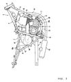
- Fig. 2 is a right side view showing a portion of the motorcycle according to the embodiment.
- FIG. 3 is a cross-sectional view of an engine unit.
- FIG. 4 (a) is a cross-sectional view of a resin-block-type belt
- FIG. 4(b) is a side view of the same.
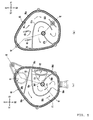
- FIGs. 5(a) and 5(b) each are developed views of a casing.
- FIG. 6 is a cross-sectional view of the casing.
- FIG. 7 is a perspective view of a second crankcase block and an inner casing.
- FIG. 8(a) is cross-sectional views of a partition wall according to a modification
- FIG. 8(b) is a cross-sectional view of a partition wall according to another modification.
- the present inventor has conducted extensive studies to suppress noise produced by a belt type continuously variable transmission having a resin-block-type belt, and found that a major portion of the noise is high-frequency sound wave, which is high-pitched noise produced by the resin-block-type belt. The inventor has also directed his attention to a fact that a high-frequency sound wave is likely to propagate rectilinearly and have low transmittance.
- the inventor Based on the study of the cause of the noise, the inventor has examined about relationships between the air passage for cooling the belt chamber and reduction of the high-frequency sound wave, and made the present invention.
- FIG. 1 shows a straddle-type vehicle according to a first embodiment is a motorcycle 1.
- the motorcycle 1 includes a body frame 2 defining a framework, and a seat 3 on which a rider or passenger is to be seated.
- the motorcycle 1 is a so-called off-road motorcycle.
- the straddle-type vehicle according to the invention is not limited to the off-road motorcycle and may be a motorcycle-type, scooter-type, so-called moped-type, or another motorcycle other than the off-road type.
- Forward, rear, left, and right directions in the following descriptions denote directions as viewed from a rider seated on the seat 3.
- FIG. 2 a right side view of a portion (components around the body frame 2) of FIG. 1 .
- the body frame 2 includes a head pipe 4, a down tube 5 extending downward from the head pipe 4, and a main tube 6 extending above the down tube 5 rearward from the head pipe 4.
- the main tube 6 extends rearward from the head pipe 4.
- the main tube 6 is bifurcated at a midway thereof to the right and to the left.
- the main tube 6 is curved at a portion rearward of the bifurcated portion to extend downward.
- a pair of left and right seat rails 7 are connected to the main tube 6 at a portion near the curved section.
- the seat rails 7 extend rearward.
- Lower ends of the left and right seat rails 7 are connected to one ends of a backstay 8.
- the other ends of the backstay 8 are connected to lower left and right bifurcated ends of the main tube 6.
- a rear arm 9 is coupled to the lower ends of the main tube 6 with a pivot shaft 10 therebetween.
- a lower end of the head pipe 4 is connected to a front fork 11 (see FIG. 1 ).
- a front wheel 12 is coupled to the front fork 11, and a rear wheel 13 is coupled to a rear end of the rear arm 9.
- a cover 14 is provided above the body frame 2 to cover the body frame 2.
- the seat 3 is at a slightly rearward position from a center of the cover 14.
- an engine unit 15 is attached to (suspended from) the down tube 5 and the main tube 6 to be positioned therebetween.
- the engine unit 15 is formed by integrating an engine 15(a) belt type continuously variable transmission (hereinafter referred to as "CVT") 17, and the like together.
- Driving force generated in the engine unit 15 is transmitted to the rear wheel 13 (see FIG. 1 ) via power transmission mechanism, such as a chain belt (not shown).
- FIG. 3 is a cross-sectional view of the engine unit 15.
- the engine unit 15 includes an engine 16, the CVT 17, a centrifugal clutch 18, and a reduction mechanism 19.
- the embodiment describes the engine 16 as being a four-cycle single-cylinder engine, however, the engine 16 may alternatively be, for example, a two-cycle engine.
- the engine 16 may be a multiple cylinder engine.
- the engine 16 includes a crankcase 20, a cylinder 21, and a cylinder head 22.
- the cylinder 21 is attached to the crankcase 20.
- the cylinder head 22 is attached to a distal end of the cylinder 21.
- a piston 25 is slidably inserted into the cylinder 21.
- the piston 25 is coupled to an end of a connecting rod 26.
- the other end of the connecting rod 26 is coupled to a crank pin 28.
- the crank pin 28 is provided between a left crank arm 27a and a right crank arm 27b of a crankshaft 23.
- An ignition plug 29 is inserted into the cylinder head 22.
- An intake pipe 40 (see FIGs. 1 and 2 ) is connected to the inlet port.
- an air cleaner 43 is connected to a rear end of the intake pipe 40.
- An intake port 43a is formed in the air cleaner 43 to induce air from the outside into the air cleaner 43.
- An exhaust pipe 41 (see FIGs. 1 and 2 ) is connected to the exhaust port. As shown in FIG. 2 , the exhaust pipe 41 extends from the cylinder head 22 frontward and obliquely downward toward the right, and then extends rearward in a curved manner passing below a transmission casing 36 of the engine unit 15 further rearward. A muffler 42 is connected to a rear end of the exhaust pipe 41.
- a cam chain chamber 31 that connects between an interior of the crankcase 20 and an interior of the cylinder head 22 is defined inside the cylinder 21 at a left portion thereof.
- a timing chain 32 is provided in the cam chain chamber 31.
- the timing chain 32 is wound around the crankshaft 23 and a cam shaft 33.
- the cam shaft 33 is provided at a top portion in the cylinder head 22 and connected with an intake valve and an exhaust valve. This configuration causes the cam shaft 33 to rotate in accordance with rotation of the crankshaft 23, which opens or closes the intake valve and the exhaust valve.
- the crankcase 20 is split into two blocks; a first crankcase block 20a on the left and a second crankcase block 20b on the right.
- the first crankcase block 20a and the second crankcase block 20b are in butt-contact with each other along a vehicle width direction.
- a recess which is recessed toward the left, is defined in a rear half of the second crankcase block 20b.
- a clutch cover 37 is situated to face the recess, and seals the recess.
- the recess defines a clutch chamber in which the centrifugal clutch 18 is provided.
- the crankshaft 23 is accommodated in the crankcase 20.
- the crankshaft 23 extending in the vehicle width direction is horizontally situated.
- the crankshaft 23 is supported by the first crankcase block 20a with a bearing 24a therebetween and supported by the second crankcase block 20b with a bearing 24b therebetween.
- a generator casing 35 is attached to a left portion of a front half of the first crankcase block 20a.
- the generator casing 35 and the first crankcase block 20a define a generator chamber.
- a generator 34 is accommodated in the generator chamber.
- the generator 34 includes a stator 34a and a rotor 34b facing the stator 34a.
- the rotor 34b is fixed to a sleeve 39 that rotates with the crankshaft 23.
- the stator 34a is fixed to the generator casing 35. This structure causes the rotor 34b to rotate relative to the stator 34a as the crankshaft 23 rotates. As a result, electricity is generated.
- the transmission casing 36 which accommodates the CVT 17, is attached to the right side of the second crankcase block 20b.
- the transmission casing 36 is independent of the crankcase 20, and has an inner casing 36a and an outer casing 36b.
- the inner casing 36a is attached to the right side of the crankcase 30, and the outer casing 36b is attached to the right side of the inner casing 36a.
- the inner casing 36a and the outer casing 36b define a belt chamber 38 that accommodates the CVT 17 therein.
- the CVT 17 includes a primary sheave 51, a secondary sheave 52, and a V-belt 55 wound around the primary sheave 51 and the secondary sheave 52.
- the primary sheave 51 is attached to the crankshaft 23. More specifically, a right end of the crankshaft 23 extends through the second crankcase block 20b and the inner casing 36a to the belt chamber 38.
- the primary sheave 51 is attached to the right end of the crankshaft 23.
- a right portion (more strictly, a portion more right than the bearing 24b) of the crankshaft 23 is referred to as a "primary sheave shaft 23a.”
- the primary sheave 51 includes a stationary sheave member 51a and a movable sheave member 51b facing the stationary sheave member 51a.
- the stationary sheave member 51a is fixed to a right portion of the primary sheave shaft 23a.
- the movable sheave member 51b is located on the left of the stationary sheave member 51a and slidably attached to the primary sheave shaft 23a.
- a belt groove is defined between the stationary sheave member 51a and the movable sheave member 51b.
- a cam surface 56 is formed on a left side surface of the movable sheave member 51b.
- a cam plate 57 is provided on the left of the cam surface 56.
- a roller weight 58 is provided between the cam surface 56 of the movable sheave member 51b and the cam plate 57.
- a plurality of vanes 60 for blowing air are formed on the right portion of the stationary sheave member 51a.
- An intake opening 78 is formed in a portion of the outer casing 36b, above the vanes 60.
- An intake duct 71 (see FIG. 2 ), which will be described later, is connected with the intake opening 78.
- a secondary sheave shaft 53 is provided in the rear half of the crankcase 20.
- the secondary sheave shaft 53 is supported at a right side of its center portion by the clutch cover 37 with a bearing 54a therebetween.
- the secondary sheave shaft 53 is supported at its left end by a left end of the second crankcase block 20b with a bearing 54b therebetween.
- the right end of the secondary sheave shaft 53 is coupled to the secondary sheave 52.
- the secondary sheave 52 includes a stationary sheave member 52a, which is on an inner side in the vehicle width direction, and a movable sheave member 52b, which is on an outer side in the vehicle width direction and opposed to the stationary sheave member 52a.
- a cylindrically-shaped shaft core of the stationary sheave member 52a is spline-fitted into the secondary sheave shaft 53.
- a V-shaped belt groove 52c is defined between the stationary sheave member 52a and the movable sheave member 52b.
- the movable sheave member 52b is attached to the right portion of the secondary sheave shaft 53.
- the movable sheave member 52b rotates with the secondary sheave shaft 53 and is slidable in an axial direction of the secondary sheave shaft 53.
- a compression coil spring 59 is provided on the right of the secondary sheave 52.
- the compression coil spring 59 urges the movable sheave member 52b leftward.
- the V-belt 55 includes a plurality of laterally-elongated, H-shaped resin blocks 55(a) and a pair of coupling members 55 (b) that couple the plurality of resin blocks 55 (a) together.
- Each resin block 55(a) is formed into a V-shape bearing an laterally-elongated-H-shaped cross section. This structure allows the resin blocks 55 (a) to conform to shapes of the belt groove 51c in the primary sheave 51 and the belt groove 52c in the secondary sheave 52 (see FIG. 3 ).
- a recess 55c which is recessed toward a center of the resin block 55 (a), is defined in each side surface of the resin block 55.
- the pair of the coupling members 55(b) are fit into the recess 55c.
- each coupling member 55 (b) extends in a direction along which the resin blocks 55(a) are aligned.
- the centrifugal clutch 18 is a multiplate wet clutch.
- the centrifugal clutch 18 includes a substantially-cylindrical clutch housing 81 and a clutch boss 82.
- the clutch housing 81 is spline-fitted into the secondary sheave shaft 53 to be rotated integrally with the secondary sheave shaft 53.
- a plurality of ring-shaped clutch plates 83 are attached to the clutch housing 81.
- the clutch plates 83 are aligned in the axial direction of the secondary sheave shaft 53 and spaced from each other.
- a cylindrical gear 85 is peripherally fitted for rotation into a left portion of the secondary sheave shaft 53 with a bearing 84 therebetween.
- the clutch boss 82 is provided at a position radially inward of the clutch plates 83 and radially outward of the gear 85 and in mesh with the gear 85. This configuration allows the gear 85 to rotate with the clutch boss 82.
- a plurality of ring-shaped friction discs 86 are attached to the clutch boss 82 at radially outward positions. The friction discs 86 are aligned in an axial direction of the secondary sheave shaft 53 and spaced from each other. Each friction disc 86 is positioned between adjacent clutch plates 83, 83.
- a plurality of cam surfaces 87 are formed on the left of the clutch housing 81.
- a roller weight 88 is provided between the cam surfaces 87 and a rightmost one of the clutch plates 83 that faces the cam surfaces 87.
- the centrifugal clutch 18 is automatically switched between a clutch-in state (engaged state) and a clutch-off state (disengaged state) according to the magnitude of a centrifugal force applied on the roller weight 88.
- the reduction mechanism 19 is interposed between the centrifugal clutch 18 and the output shaft (not shown).
- the reduction mechanism 19 has a speed change shaft 89 situated parallel with the secondary sheave shaft 53.
- the speed change shaft 89 is rotatably supported by the first crankcase block 20a with a bearing 90 therebetween.
- the speed change shaft 89 is also rotatably supported by the second crankcase block 20b with a bearing 91 therebetween.
- a first speed-change gear 92 to be brought into engagement with the gear 85 is provided on a right end of the speed change shaft 89.
- a second speed change gear 93 of which diameter is smaller than that of the first speed change gear 92, is provided centrally on the speed change shaft 89.
- the second speed change gear 93 is positioned for engagement with the output shaft (not shown) or a gear (not shown) provided on the output shaft.
- the clutch boss 82 and the output shaft are coupled together with the gear 85, the first speed change gear 92, the speed change shaft 89, the second speed change gear 93, and the like therebetween. Accordingly, as the clutch boss 82 rotates, the output shaft rotates.
- a power transmission mechanism such as a chain for transmitting a driving force from the output shaft to the rear wheel 13 (see FIG. 1 ) is wound around the output shaft.
- the power transmission mechanism is not limited to the chain, and can be a transmission belt, a gear mechanism formed by combining a plurality of gears, a drive shaft, or a like member.
- the structure of the engine unit 15 has been described above. Next, the structure of the belt chamber 38 for inducing cooling air will be described.
- the intake duct 71 is connected to a front portion (front portion of the outer casing 36b) of the transmission casing 36.
- the intake duct 71 extends upward from the transmission casing 36, and then extends rearward.
- the intake duct 71 extends to a position rearward of the main tube 6.
- a closed casing 94 is connected to a rear end of the intake duct 71.
- the closed casing 94 is blow the seat 3 (see FIG. 1 ).
- the closed casing 94 is situated such that an inlet port 61, which will be described later, is at a position higher than the pivot shaft 10.
- the intake duct 71 and the closed casing 94 form an air passage for guiding air from the outside into the belt chamber 38 (see FIG. 3 ).
- FIGs. 5(a) and 5(b) are each a developed view of the closed casing 94.
- FIG. 6 is a cross-sectional view of the closed casing 94.
- X1, X2, Y1, Y2, Z1, and Z2 directions are defined as shown in FIGs. 5(a) to 6 with respect to the closed casing 94.
- Straight lines X1-X2, Y1-Y2, and Z1-Z2 intersect at right angles one another.
- the closed casing 94 is formed with a dish-shaped first casing member 95 and a dish-shaped second casing member 96.
- the first casing member 95 and the second casing member 96 are shaped such that developed faces thereof conform to each other.
- the first casing member 95 and the second casing member 96 are aligned in the Z direction (Z1-Z2 direction) and assembled together with the conforming faces abutted each other. More specifically, a rib 96a (see FIG. 5(a) ) provided upright on a periphery of the second casing member 96 is fitted into a recess 95 (a) (see FIG. 5(b) ) defined in a periphery of the first casing member 95.
- a bolt 99 fastens the first casing member 95 and the second casing member 96 together.
- the inlet port 61 is formed in the second casing member 96. As shown in FIG. 6 , the inlet port 61 is formed in the second casing member 96 centrally in the Z direction and faces the first casing member 95. As shown in FIG. 5(a) , an exhaust port 62 is formed in the second casing member 96 on a side surface facing the Y2 direction.
- a partition wall 63 is formed on the second casing member 96 at a position spaced from the inlet port 61 in the X2 direction.
- the partition wall 63 partitions a space in the second casing member 96 into a space on the inlet port 61 side and a space on the exhaust port 62 side.
- the partition wall 63 projects out of the second casing member 96 toward the inside of the closed casing 94 (in the Z1 direction).
- the partition wall 63 is formed integrally with the second casing member 96.
- the partition wall 63 and the second casing member 96 form an air flow path 64a.
- the air flow path 64a extends from the inlet port 61 toward the first casing member 95.
- partition walls 98a and 98b are formed on the second casing member 96.
- the partition walls 98a and 98b are formed integrally with the second casing member 96.
- the partition walls 98a and 98b project out of the second casing member 96 toward the inside of the closed casing 94 (in the Z1 direction) (see FIG. 6 ).
- the partition walls 98a and 98b, and the second casing member 96 form an air flow path 64c.
- a longitudinal end 98c of the partition wall 98a and a longitudinal end 98d of the partition wall 98b are connected with an inner wall of the closed casing 94 as viewed from a projecting direction (Z1 direction) of the partition walls 98a and 98b.
- the other longitudinal ends 98e and 98f of the partition walls 98a and 98b are separated from the inner wall of the closed casing 94.
- Each of the partition walls 98a and 98b has side surfaces extending in a direction intersecting with the projecting direction (Z1 direction).
- a first flow path F1 that runs from the one end 98c of the partition wall 98a to the other end 98e of the same is formed on a side of one of the side surfaces of the partition wall 98a.
- a second flow path F2 for guiding air from the one end 98c of the partition wall 98a to the other end 98e of the same is formed on a side of the other side surface of the partition wall 98a.
- the second flow path F2 is connected with a downstream end of the first flow path F1. Flow directions of the flow paths F1 and F2 are opposite from each other with the partition wall 98a therebetween.
- the flow paths F1 and F2 form a U-shaped flow path.
- the second flow path F2 is formed on a side of one of the side surfaces of the partition wall 98b so as to guide air from the one end 98d of the partition wall 98b toward the other end 98f.
- a third flow path F3 that runs from the other end 98f of the partition wall 98b to the one end 98d is formed on a side of the other side surface of the partition wall 98b.
- the third flow path F3 is connected with a downstream end of the second flow path F2. Flow directions of the flow paths F2 and F3 are opposite from each other with the partition wall 98b therebetween. Thus, the flow paths F2 and F3 form a U-shaped flow path.
- the air flow path 64c includes the U-shaped flow paths, thereby forming a serpentine flow.
- a bottom (a surface facing the Z2 direction) of the second casing member 96 is recessed from a surface of the inlet port 61 in the Z2 direction toward the exhaust port 62 (see FIG. 6 ). Accordingly, a depth in the Z direction and a cross-sectional area of the air flow path 64c increase toward its downstream end (neighborhood of the exhaust port 62).
- a support 65 supporting the partition wall 63 (see FIG. 5(a) ) is formed in the first casing member 95. As shown in FIG. 6 , the support 65 engages with the partition wall 63 provided on the second casing member 96.
- partition walls 97a and 97b which are correspondingly shaped to the partition walls 98a and 98b (see FIG. 5(a) ), respectively, are attached to the first casing member 95.
- the partition walls 97a and 97b are formed integrally with the first casing member 95 and project out of the first casing member 95 toward the inside of the closed casing 94 (in the Z2 direction) (see FIG. 6 ).
- the partition walls 97a and 97b, and the first casing member 95 form an air flow path 64b. As shown in FIG. 6 , the air flow path 64b is connected with a downstream end of the air flow path 64a formed in the second casing member 96. Details of the partition walls 97a and 97b, curved flow paths formed by the same, and the like are similar to those of the partition walls 98a and 98b, and hence repeated descriptions are omitted.
- the partition walls 98a and 97a are butt-joined together and the partition walls 98b and 97b are butt-joined together. Consequently, the air flow paths 64b and 64c are butt-joined. As shown in FIG. 6 , the air flow paths 64a, 64b, and 64c form an air flow path 64 that guides air from the inlet port 61 (see FIG. 5(a) ) to the exhaust port 62 (see FIG. 5(a) ).
- an air filter 79 for filtering out dusts from air to thereby clean the air is provided between the first casing member 95 and the second casing member 96 at a position spaced from the support 65 in the X2 direction.
- the air filter 79 is sandwiched between the partition walls 97a and 97b, and the partition walls 98a and 98b to be held therebetween.
- the air flow path 64 is partitioned at a midway thereof by the air filter 79 into the air flow path 64b on the inlet port 61 side and the air flow path 64c on the exhaust port 62 side.
- FIG. 7 is a perspective view of the second crankcase block 20b and the inner casing 36a.
- a front half 66 of the inner casing 36a bulges out leftward into a bowl shape
- a rear half 67 of the inner casing 36a bulges out rightward into a bowl shape.
- a hole 68, into which the primary sheave shaft 23a (see FIG. 3 ) of the CVT 17 is to be inserted, is defined in the front half 66.
- a hole 69, into which the secondary sheave shaft 53 (see FIG. 3 ) of the CVT 17 is to be inserted, is defined in the rear half 67.
- the clutch cover 37 (see FIG. 3 ) interposed between the inner casing 36a and the second crankcase block 20b is not shown in FIG. 7 .
- a ventilation hole 72 is defined in the inner casing 36a.
- three circular ventilation holes 72 are provided at positions higher than a vertical center of the inner casing 36a. It should be noted that no limitation is imposed on the shape of the ventilation hole 72.
- the position of the ventilation hole 72 is not limited to an upper portion of the inner casing 36a.
- the ventilation holes 72 are provided in both the front half 66 and the rear half 67 of the inner casing 36a. Alternatively, the ventilation hole 72 may be provided only in either one of the front half 66 and the rear half 67. No limitation is imposed on the number of the ventilation hole 72 as well.
- a plurality of ventilation holes 73 are defined in a lower side of a right portion of the second crankcase block 20b. More specifically, the second crankcase block 20b has a rim 74 that stands upright rightward. The rim 74 is correspondingly shaped to an outline of the transmission casing 36. A lower side of the rim 74 is formed into a partially-notched slits; in other words, formed into a so-called comb-like shape. Accordingly, a space 75 defined by the second crankcase block 20b and the inner casing 36a is in communication with the external of the engine unit 15 (see FIG. 3 ) through the ventilation holes 73. Because a right side of the rear half of the second crankcase block 20b is covered with the clutch cover 37, the space 75 in the rear half of the second crankcase block 20b is defined between the clutch cover 37 and the inner casing 36a (see FIG. 3 ).
- Reinforcing ribs 76 are provided on the comb-like portion of the rim 74.
- An oil pan 77 is provided below the ventilation holes 73.
- each ventilation hole 73 is not limited to a slit, and the ventilation hole 73 may be an opening of another shape such as a circular opening. No limitation is imposed on the shape, size, and the number of the ventilation holes 73 in the second crankcase block 20b.
- the air After passing through the inlet port 61, the air is first guided into the air flow path 64a and then guided in the Z1 direction along the partition wall 63 (see FIG. 6 ). Thus, the air flows to the side of the first casing member 95 and enters the air flow path 64b.
- a negative pressure generated near the exhaust port 62 causes a portion of the air flowing in the air flow path 64b to flow in the Z2 direction (see FIG. 6 ). In the course of flowing in the Z2 direction, the air passes through the air filter 79.
- the air After reaching the exhaust port 62, the air passes through the intake duct 71 to be sucked into the belt chamber 38.
- the air sucked into the belt chamber 38 flows around the primary sheave 51, the secondary sheave 52, and the V-belt 55, thereby cooling the primary sheave 51, the secondary sheave 52, and the V-belt 55.
- the air having cooled the primary sheave 51, the secondary sheave 52, and the V-belt 55 is discharged out of the belt chamber 38 through the ventilation holes 72 in the inner casing 36a, and flows into the space 75 between the inner casing 36a and the second crankcase block 20b (see FIG. 7 ).
- the air in the space 75 is discharged out of the engine unit 15 through the ventilation holes 73 defined in the lower portion of the second crankcase block 20b.
- the CVT 17 is continuously cooled by the air flow described above.
- the partition walls 98a and 98b and the partition walls 97a and 97b form curved flow paths in the closed casing 94.
- the flow path F1 is formed on the one side of the partition walls 98a and 97a and the flow path F2 is formed on the other side such that flow directions of the flow paths F1 and F2 are opposite from each other with the partition walls 98a and 97a therebetween.
- the flow path F2 is formed on the one side of the partition walls 98b and 97b and the flow path F3 is formed the other side such that flow directions of the flow paths F2 and F3 are opposite from each other with the partition walls 98b and 97b therebetween.
- This structure forms the curved flow paths in the closed casing 94 especially compact. Forming the curved flow paths in the closed casing 94 as described above allows to form a long flow path within a confined space. Accordingly, noise produced by the resin-block-type belt (V-belt) 55 in the belt chamber 38 is effectively reduced in the closed casing 94 before escaping outside.
- an air flow path is preferably not curved. Nevertheless, in the motorcycle 1, the flow path is intentionally curved in the closed casing 94.
- This structure allows to prevent rectilinear propagation of high-frequency sound waves that are likely to propagate rectilinearly. Accordingly, leakage of high-frequency sound waves produced by the resin-block-type belt (V-belt) 55 from inside the belt chamber 38 to the outside can be prevented.
- noise produced by the resin-block-type belt (V-belt) 55 can be favorably suppressed.
- the longitudinal end 98c of the partition wall 98a and the longitudinal end 98d of the partition wall 98b are continuing to the inner wall of the closed casing 94 as viewed from the projecting directions (Z1 direction) of the partition walls 98a and 98b.
- the other ends 98a and 98f are separated from the inner wall of the closed casing 94.
- a U-shaped flow path is formed in the closed casing 94.
- the partition walls 97a and 97b in the similar manner to that of the partition walls 98a and 98b, another U-shaped flow path is formed in the closed casing 94 as well.
- the U-shaped flow paths are formed in the closed casing 94 with the simple structure.
- a plurality of partition walls that form the U-shaped flow paths are provided.
- This structure causes the air flow paths 64b and 64c to have at least two U-shaped curves within the closed casing 94 to thereby form a serpentine flow path. Accordingly, the motorcycle 1 is capable of suppressing leakage of high-frequency sound waves more effectively, thereby reducing noise produced by the resin-block-type belt (V-belt) 55 more effectively.
- the shape of the closed casing 94 is not limited to that of the embodiment, and the number and shape of the partition walls are not limited to those of the embodiment. That is, as a matter of course, three or more partition walls may be provided in the closed casing 94.
- the partition walls 97a and 97b are formed integrally with the first casing member 95 and the partition walls 98a and 98b are formed integrally with the second casing member 96.
- This structure allows the partition walls 97a, 97b, 98a, and 98b easily to be formed in the closed casing 94.
- partitions according to the present invention are formed with the partition walls 97a, 97b, 98a, and 98b each formed with a plate piece. This structure allows to secure a large length of the air flow path 64 within the closed casing 94 and to form the closed casing 94 compact.
- the closed casing 94 of the motorcycle 1 is formed with two members; the first casing member 95 and the second casing member 96, which are aligned in the Z direction (the projecting direction of the partition walls 97a, 97b, 98a, and 98b).
- This structure allows the partition walls 97a, 97b, 98a, and 98b to be located within the closed casing 94 easily.
- the inlet port 61, the exhaust port 62, and the partition wall 63 are provided in the second casing member 96.
- the partition wall 63 partitions a space in the second casing member 96 into a space on the side of the inlet port 61 and that on the side of the exhaust port 62, and projects out of the second casing member 96 toward the inside of the closed casing 94 (in the Z1 direction).
- the partition wall 63 forms the air flow path 64 (air flow paths 64a, 64b, and 64c) such that the air flow path 64 extends from the inlet port 61 toward the first casing member 95, turns back in the first casing member 95 and then extends toward the exhaust port 62.
- the air flow path 64 meanders not only in the X-Y plane shown in FIGs. 5 (a) and 5(b) but also in the Z-X plane shown in FIG. 6 ; that is, the air flow path 64 three-dimensionally meanders.
- This structure allows the motorcycle 1 to suppress leakage of high-frequency sound waves more effectively, thereby reducing noise produced by the resin-block-type belt (V-belt) 55 more effectively.
- the air passage according to the invention is an intake passage that guides air into the belt chamber 38.
- the air flow path 64 formed in the closed casing 94 is upstream of the belt chamber 38.
- the air filter 79 is provided between the inlet port 61 and the exhaust port 62 of the air flow path 64.
- the air filter 79 is located at a position between the inlet port 61 and the exhaust port 62 of the air flow path 64 as well as between the first casing member 95 and the second casing member 95 that form the closed casing 94.
- the air filter 79 can be attached to the motorcycle 1 easily even when the air flow path 64 is formed into a complicated shape to suppress noise. This can reduce a work and cost necessary for maintenance.
- the present inventor has conducted extensive studies and found that air guided by the plurality of air-inducing vanes 60 into the belt chamber 38 is a steady flow rather than a pulsating flow of air aspirated by the engine 16, and that an air chamber for temporarily storing cooling air for the CVT 17 thereby suppressing pulsation of the air flow is unnecessary. Based on the finding, an air chamber for storing cooling air of the CVT 17 is not provided in the motorcycle 1.
- This structure allows the motorcycle 1 to have a large space for installing the closed casing 94 inside the body frame 2. Accordingly, the air flow path 64 can be formed long, thereby suppressing the noise produced by the resin-block-type belt (V-belt) 55 more effectively.
- the closed casing 94 is formed independently of the air cleaner 43 for the engine 16. This structure allows to secure a larger space for the air flow path 64 as compared to a structure in which the closed casing 94 is formed integrally with the air cleaner 43 for the engine 16. Accordingly, the air flow path 64 can be formed long, thereby suppressing the noise produced by the resin-block-type belt (V-belt) 55 more effectively.
- the inlet port 61 in the closed casing 94 of the motorcycle 1 is located below the seat 3. According to this arrangement, the inlet port 61 is covered with the seat 3 from above. This allows to prevent entry of rain, dusts, or the like into the closed casing 94 through the inlet port 61.
- the inlet port 61 is located above the pivot shaft 10. That is, the inlet port 61 is at a position away from the ground by a relatively large distance, where the inlet port 61 less easily sucks water and dusts. Hence, the motorcycle 1 is capable of supplying clean air to the belt chamber 38.
- the closed casing 94 is located below the seat 3, and the intake duct 71 is connected with the closed casing 94 at one end and connected with a front portion of the transmission casing 36 at the other end.
- This structure allows to form a long the intake duct 71.
- the air flow path 64 that is formed by the intake duct 71 and the partition walls 97a, 97b, 98a, and 98b can be formed long. This allows more effective suppression of the noise produced by the resin-block-type belt (V-belt) 55.
- the exhaust pipe 41 of the engine 16 extends rearward passing below the transmission casing 36 of the CVT 17.
- This arrangement allows to prevent interference between the exhaust pipe 41 and the closed casing 94 easily.
- the closed casing 94 can be formed large without being obstructed by the exhaust pipe 41.
- the air flow path 64 can be formed long, thereby suppressing the noise produced by the resin-block-type belt (V-belt) 55 more effectively.
- the vanes 60 for blowing air are formed on the outer side of the stationary sheave member 51a of the primary sheave 51. This structure allows air to be guided from the outside into the belt chamber 38 smoothly even when the air passage is formed long as in the case of the invention. Thus, according to the motorcycle 1, suppression of noise and improvement of cooling capability of the CVT 17 are attained.
- the air passage according to the invention is not limited to such an intake passage, and may be an exhaust passage.
- the transmission casing 36 preferably has, e.g., an additional intake duct or intake opening.
- the exhaust passage serving as the air passage according to the invention can be formed compact and long.
- the exhaust passage serving as the air passage according to the invention can be formed into a serpentine flow path. Accordingly, leakage of noise produced by the V-belt 51 from the belt chamber 38 in the transmission casing 36 through the exhaust passage can be prevented.
- the motorcycle 1 is capable of favorably suppressing the noise produced by the resin-block-type belt (V-belt) 55.
- the "plate piece" forming each of the partition walls 98a, 98b, 97a, and 97b serving as the partition has a smooth curved surface.
- a shape of the "plate piece” is not limited to those shown in FIGs. 5(a) and 5(b) .
- the plate piece may have an uneven surface as shown in FIG. 8(a) .
- the plate piece may have a hollow therein as shown in FIG. 8(b) .
- the partition walls 98a and 98b are formed integrally with the second casing member 96.
- the partition walls 98a and 98b may be formed independently of the second casing member 96, and fixed together by adhesion or a like method.
- the partition walls 97a and 97b may be formed independently of the first casing member 95, or the partition wall 63 may be formed independently of the second casing member 96.
- noise produced by the resin-block-type belt (V-belt) 55 of a saddle-ride-type other than the motorcycle 1 can be suppressed as well.
- a long air passage can be secured within a small space. This exhibits particularly significant effects to vehicles such as the motorcycle 1 according to the embodiment, for which widening its vehicle width is unfavorable.
- the embodiments have been described about an example structure in which the transmission casing 36 has no sound absorber therein.
- the invention does not exclude installation of a sound absorber on an inner surface of the transmission casing 36.
- a sound absorber can be installed on, e.g., an inner surface of the transmission casing 36 to thereby suppress noise more effectively.
Landscapes
- Engineering & Computer Science (AREA)
- General Engineering & Computer Science (AREA)
- Mechanical Engineering (AREA)
- Physics & Mathematics (AREA)
- Thermal Sciences (AREA)
- General Details Of Gearings (AREA)
- Transmissions By Endless Flexible Members (AREA)
Abstract
Description
- The present invention relates to a straddle-type vehicle provided with a belt type continuously variable transmission having a resin-block-type belt.
- Straddle-type vehicles, such as a motorcycle, provided with a belt type continuously variable transmission have been known (see
JP-A-2002-147582 - A belt type continuously variable transmission includes a primary sheave, a secondary sheave, and a V-belt wound around the primary sheave and the secondary sheave. Driving force of an engine is transmitted via a crankshaft to the primary sheave, the V-belt, and the secondary sheave in this order to change a speed ratio, and thereafter transmitted to drive wheels. The primary sheave, the V-belt, and the secondary sheave are housed in a transmission casing. More specifically, a belt chamber for housing the primary sheave, the V-belt, and the secondary sheave therein is defined in the transmission casing.
- In the motorcycle disclosed in
JP-A-2002-147582 - To this end, providing a sound absorber on an inner surface of a transmission casing, which accommodates the resin-block-type belt, to thereby suppress noise is proposed in the motorcycle disclosed in
JP-A-2002-147582 - The V-belt, and the primary sheave and the secondary sheave wound by the V-belt rotate at a high speed. A sound absorber should be located so as not to come into contact with any of the V-belt and the sheaves. In other words, the sound absorber is to be located at a position away from both the V-belt and the sheaves by a certain distance. Accordingly, when the sound absorber is provided on an inner surface of a transmission casing as in the case of the motorcycle disclosed in
JP-A-2002-147582 JP-A-2002-147582 - Meanwhile, sound absorbers generally have heat-retaining property. Accordingly, the temperature inside the belt chamber of the motorcycle disclosed in
JP-A-2002-147582 - The present invention sseks to provide a noise suppressor appropriate for a straddle-type vehicle provided with a belt type continuously variable transmission having a resin-block-type belt.
- An aspect of the present invention provides a saddle-ride type motorcycle including: an engine unit having an engine, a belt type continuously variable transmission having a resin-block-type belt, and a transmission casing, in which a belt chamber for accommodating the belt type continuously variable transmission therein is defined; and an air passage that is either an intake passage for guiding air into the belt chamber or an exhaust passage for venting air out of the belt chamber. The air passage includes: a closed casing, in which an inlet port and an exhaust port are formed; and one or more partitions each projecting out of an inner wall of the closed casing toward an inside of the closed casing and having opposite side surfaces extending in a direction intersecting with a projecting direction of the partition. A flow path is formed on each of a side of one of the side surfaces of the partition and a side of the other side surface. Flow directions of the flow paths are opposite from each other. The flow paths form a curved flow path that runs from the inlet port to the exhaust port in the closed casing.
- In the straddle-type vehicle, the air passage includes the closed casing and the partition that forms the curved flow path in the closed casing. When a flow path is curved inside the closed casing as described above, the flow path can be formed long in a confined space. Accordingly, noise produced by the resin-block-type belt in the belt chamber is effectively reduced in the closed casing before escaping outside.
- Meanwhile, from a viewpoint of smooth air flow for inducing and exhausting air without stagnation, an air flow path is preferably not curved. Nevertheless, in the closed casing of the straddle-type vehicle, a curved flow path is intentionally formed using the partitions. This structure allows to inhibit rectilinear propagation of high-frequency sound waves that are likely to propagate rectilinearly. Hence, leakage of high-frequency sound waves produced by the resin-block-type belt from inside the belt chamber to the outside can be suppressed. Thus, the straddle-type vehicle is capable of favorably suppressing noise produced by the resin-block-type belt.
- An embodiment of the present invention provides a noise suppressor appropriate for a straddle-type vehicle provided with a belt type continuously variable transmission having a resin-block-type belt.
- As described above, the present invention is useful for straddle-type vehicles such as a motorcycle.
- Embodiments of the invention are described hereinafter, by way of example only, with reference to the accompanying drawings.
-
FIG. 1 is a side view of a motorcycle according to an embodiment of the present invention. -
Fig. 2 is a right side view showing a portion of the motorcycle according to the embodiment. -
FIG. 3 is a cross-sectional view of an engine unit. -
FIG. 4 (a) is a cross-sectional view of a resin-block-type belt, andFIG. 4(b) is a side view of the same. -
FIGs. 5(a) and 5(b) each are developed views of a casing. -
FIG. 6 is a cross-sectional view of the casing. -
FIG. 7 is a perspective view of a second crankcase block and an inner casing. -
FIG. 8(a) is cross-sectional views of a partition wall according to a modification, andFIG. 8(b) is a cross-sectional view of a partition wall according to another modification. - The present inventor has conducted extensive studies to suppress noise produced by a belt type continuously variable transmission having a resin-block-type belt, and found that a major portion of the noise is high-frequency sound wave, which is high-pitched noise produced by the resin-block-type belt. The inventor has also directed his attention to a fact that a high-frequency sound wave is likely to propagate rectilinearly and have low transmittance.
- Based on the study of the cause of the noise, the inventor has examined about relationships between the air passage for cooling the belt chamber and reduction of the high-frequency sound wave, and made the present invention.
-
FIG. 1 shows a straddle-type vehicle according to a first embodiment is a motorcycle 1. The motorcycle 1 includes a body frame 2 defining a framework, and aseat 3 on which a rider or passenger is to be seated. The motorcycle 1 is a so-called off-road motorcycle. The straddle-type vehicle according to the invention is not limited to the off-road motorcycle and may be a motorcycle-type, scooter-type, so-called moped-type, or another motorcycle other than the off-road type. Forward, rear, left, and right directions in the following descriptions denote directions as viewed from a rider seated on theseat 3. -
FIG. 2 a right side view of a portion (components around the body frame 2) ofFIG. 1 . As shown inFIG. 2 , the body frame 2 includes a head pipe 4, adown tube 5 extending downward from the head pipe 4, and amain tube 6 extending above thedown tube 5 rearward from the head pipe 4. Themain tube 6 extends rearward from the head pipe 4. Themain tube 6 is bifurcated at a midway thereof to the right and to the left. Themain tube 6 is curved at a portion rearward of the bifurcated portion to extend downward. - A pair of left and right seat rails 7 are connected to the
main tube 6 at a portion near the curved section. The seat rails 7 extend rearward. Lower ends of the left and right seat rails 7 are connected to one ends of abackstay 8. The other ends of thebackstay 8 are connected to lower left and right bifurcated ends of themain tube 6. Arear arm 9 is coupled to the lower ends of themain tube 6 with apivot shaft 10 therebetween. - A lower end of the head pipe 4 is connected to a front fork 11 (see
FIG. 1 ). As shown inFIG. 1 , a front wheel 12 is coupled to thefront fork 11, and a rear wheel 13 is coupled to a rear end of therear arm 9. Acover 14 is provided above the body frame 2 to cover the body frame 2. Theseat 3 is at a slightly rearward position from a center of thecover 14. - As shown in
FIG. 2 , anengine unit 15 is attached to (suspended from) thedown tube 5 and themain tube 6 to be positioned therebetween. As shown inFIG. 3 , theengine unit 15 is formed by integrating an engine 15(a) belt type continuously variable transmission (hereinafter referred to as "CVT") 17, and the like together. Driving force generated in theengine unit 15 is transmitted to the rear wheel 13 (seeFIG. 1 ) via power transmission mechanism, such as a chain belt (not shown). -
FIG. 3 is a cross-sectional view of theengine unit 15. As shown inFIG. 3 , theengine unit 15 includes anengine 16, theCVT 17, a centrifugal clutch 18, and areduction mechanism 19. The embodiment describes theengine 16 as being a four-cycle single-cylinder engine, however, theengine 16 may alternatively be, for example, a two-cycle engine. Theengine 16 may be a multiple cylinder engine. - The
engine 16 includes acrankcase 20, acylinder 21, and acylinder head 22. Thecylinder 21 is attached to thecrankcase 20. Thecylinder head 22 is attached to a distal end of thecylinder 21. - A
piston 25 is slidably inserted into thecylinder 21. Thepiston 25 is coupled to an end of a connectingrod 26. The other end of the connectingrod 26 is coupled to a crankpin 28. Thecrank pin 28 is provided between aleft crank arm 27a and aright crank arm 27b of a crankshaft 23. - A
recess 22a, and an inlet port and an exhaust port, which are not shown both of which communicate with therecess 22a, are defined in thecylinder head 22. An ignition plug 29 is inserted into thecylinder head 22. - An intake pipe 40 (see
FIGs. 1 and2 ) is connected to the inlet port. As shown inFIG. 2 , anair cleaner 43 is connected to a rear end of the intake pipe 40. Anintake port 43a is formed in theair cleaner 43 to induce air from the outside into theair cleaner 43. - An exhaust pipe 41 (see
FIGs. 1 and2 ) is connected to the exhaust port. As shown inFIG. 2 , theexhaust pipe 41 extends from thecylinder head 22 frontward and obliquely downward toward the right, and then extends rearward in a curved manner passing below atransmission casing 36 of theengine unit 15 further rearward. Amuffler 42 is connected to a rear end of theexhaust pipe 41. - As shown in
FIG. 3 , a cam chain chamber 31 that connects between an interior of thecrankcase 20 and an interior of thecylinder head 22 is defined inside thecylinder 21 at a left portion thereof. Atiming chain 32 is provided in the cam chain chamber 31. Thetiming chain 32 is wound around the crankshaft 23 and acam shaft 33. Thecam shaft 33 is provided at a top portion in thecylinder head 22 and connected with an intake valve and an exhaust valve. This configuration causes thecam shaft 33 to rotate in accordance with rotation of the crankshaft 23, which opens or closes the intake valve and the exhaust valve. - The
crankcase 20 is split into two blocks; afirst crankcase block 20a on the left and asecond crankcase block 20b on the right. Thefirst crankcase block 20a and thesecond crankcase block 20b are in butt-contact with each other along a vehicle width direction. A recess, which is recessed toward the left, is defined in a rear half of thesecond crankcase block 20b. Aclutch cover 37 is situated to face the recess, and seals the recess. The recess defines a clutch chamber in which the centrifugal clutch 18 is provided. - The crankshaft 23 is accommodated in the
crankcase 20. The crankshaft 23 extending in the vehicle width direction is horizontally situated. The crankshaft 23 is supported by thefirst crankcase block 20a with abearing 24a therebetween and supported by thesecond crankcase block 20b with abearing 24b therebetween. - A
generator casing 35 is attached to a left portion of a front half of thefirst crankcase block 20a. Thegenerator casing 35 and thefirst crankcase block 20a define a generator chamber. Agenerator 34 is accommodated in the generator chamber. Thegenerator 34 includes astator 34a and arotor 34b facing thestator 34a. Therotor 34b is fixed to asleeve 39 that rotates with the crankshaft 23. Thestator 34a is fixed to thegenerator casing 35. This structure causes therotor 34b to rotate relative to thestator 34a as the crankshaft 23 rotates. As a result, electricity is generated. - The
transmission casing 36, which accommodates theCVT 17, is attached to the right side of thesecond crankcase block 20b. Thetransmission casing 36 is independent of thecrankcase 20, and has aninner casing 36a and anouter casing 36b. Theinner casing 36a is attached to the right side of the crankcase 30, and theouter casing 36b is attached to the right side of theinner casing 36a. Theinner casing 36a and theouter casing 36b define abelt chamber 38 that accommodates theCVT 17 therein. - The
CVT 17 includes aprimary sheave 51, asecondary sheave 52, and a V-belt 55 wound around theprimary sheave 51 and thesecondary sheave 52. Theprimary sheave 51 is attached to the crankshaft 23. More specifically, a right end of the crankshaft 23 extends through thesecond crankcase block 20b and theinner casing 36a to thebelt chamber 38. Theprimary sheave 51 is attached to the right end of the crankshaft 23. In the following descriptions, a right portion (more strictly, a portion more right than the bearing 24b) of the crankshaft 23 is referred to as a "primary sheave shaft 23a." - The
primary sheave 51 includes astationary sheave member 51a and amovable sheave member 51b facing thestationary sheave member 51a. Thestationary sheave member 51a is fixed to a right portion of theprimary sheave shaft 23a. Themovable sheave member 51b is located on the left of thestationary sheave member 51a and slidably attached to theprimary sheave shaft 23a. - A belt groove is defined between the
stationary sheave member 51a and themovable sheave member 51b. Acam surface 56 is formed on a left side surface of themovable sheave member 51b. Acam plate 57 is provided on the left of thecam surface 56. Aroller weight 58 is provided between thecam surface 56 of themovable sheave member 51b and thecam plate 57. - A plurality of
vanes 60 for blowing air are formed on the right portion of thestationary sheave member 51a. Anintake opening 78 is formed in a portion of theouter casing 36b, above thevanes 60. An intake duct 71 (seeFIG. 2 ), which will be described later, is connected with theintake opening 78. - A
secondary sheave shaft 53 is provided in the rear half of thecrankcase 20. Thesecondary sheave shaft 53, into which thesecondary sheave 52 is fitted, extends parallel with the crankshaft 23. Thesecondary sheave shaft 53 is supported at a right side of its center portion by theclutch cover 37 with abearing 54a therebetween. Thesecondary sheave shaft 53 is supported at its left end by a left end of thesecond crankcase block 20b with abearing 54b therebetween. The right end of thesecondary sheave shaft 53 is coupled to thesecondary sheave 52. - The
secondary sheave 52 includes astationary sheave member 52a, which is on an inner side in the vehicle width direction, and amovable sheave member 52b, which is on an outer side in the vehicle width direction and opposed to thestationary sheave member 52a. A cylindrically-shaped shaft core of thestationary sheave member 52a is spline-fitted into thesecondary sheave shaft 53. A V-shapedbelt groove 52c is defined between thestationary sheave member 52a and themovable sheave member 52b. Themovable sheave member 52b is attached to the right portion of thesecondary sheave shaft 53. Themovable sheave member 52b rotates with thesecondary sheave shaft 53 and is slidable in an axial direction of thesecondary sheave shaft 53. - A
compression coil spring 59 is provided on the right of thesecondary sheave 52. Thecompression coil spring 59 urges themovable sheave member 52b leftward. - As shown in
FIG. 4(a) , the V-belt 55 includes a plurality of laterally-elongated, H-shaped resin blocks 55(a) and a pair of coupling members 55 (b) that couple the plurality of resin blocks 55 (a) together. Each resin block 55(a) is formed into a V-shape bearing an laterally-elongated-H-shaped cross section. This structure allows the resin blocks 55 (a) to conform to shapes of thebelt groove 51c in theprimary sheave 51 and thebelt groove 52c in the secondary sheave 52 (seeFIG. 3 ). Arecess 55c, which is recessed toward a center of the resin block 55 (a), is defined in each side surface of theresin block 55. The pair of the coupling members 55(b) are fit into therecess 55c. As shown inFIG. 4(b) , each coupling member 55 (b) extends in a direction along which the resin blocks 55(a) are aligned. - As shown in
FIG. 3 , the centrifugal clutch 18 is a multiplate wet clutch. The centrifugal clutch 18 includes a substantially-cylindricalclutch housing 81 and a clutch boss 82. Theclutch housing 81 is spline-fitted into thesecondary sheave shaft 53 to be rotated integrally with thesecondary sheave shaft 53. A plurality of ring-shapedclutch plates 83 are attached to theclutch housing 81. Theclutch plates 83 are aligned in the axial direction of thesecondary sheave shaft 53 and spaced from each other. - A
cylindrical gear 85 is peripherally fitted for rotation into a left portion of thesecondary sheave shaft 53 with abearing 84 therebetween. The clutch boss 82 is provided at a position radially inward of theclutch plates 83 and radially outward of thegear 85 and in mesh with thegear 85. This configuration allows thegear 85 to rotate with the clutch boss 82. A plurality of ring-shapedfriction discs 86 are attached to the clutch boss 82 at radially outward positions. Thefriction discs 86 are aligned in an axial direction of thesecondary sheave shaft 53 and spaced from each other. Eachfriction disc 86 is positioned between adjacentclutch plates - A plurality of cam surfaces 87 are formed on the left of the
clutch housing 81. Aroller weight 88 is provided between the cam surfaces 87 and a rightmost one of theclutch plates 83 that faces the cam surfaces 87. - The centrifugal clutch 18 is automatically switched between a clutch-in state (engaged state) and a clutch-off state (disengaged state) according to the magnitude of a centrifugal force applied on the
roller weight 88. - More specifically, when the
clutch housing 81 rotates at a rotational speed equal to or higher than a predetermined speed, theroller weight 88 is moved radially outward by a centrifugal force, thereby pressing theclutch plates 83 leftward. This consequently brings theclutch plates 83 and thefriction discs 86 into press-contact with each other and hence into the clutch-in state, in which a driving force is transmitted from thesecondary sheave shaft 53 to an output shaft 85 (not shown) via thecentrifugal clutch 18. - On the other hand, when a rotational speed of the
clutch housing 81 decreases to be lower than the predetermined speed, the centrifugal force exerted on theroller weight 88 decreases, causing theroller weight 88 to move radially inward. This consequently releases the press-contact between theclutch plates 83 and thefriction discs 86, and hence brings theclutch plates 83 and thefriction discs 86 into the clutch-off state, in which a driving force is not transmitted from thesecondary sheave shaft 53 theoutput shaft 85. InFIG. 3 , a portion below thesecondary sheave shaft 53 indicates the clutch-in state, and a portion above the same indicates the clutch-off state. - The
reduction mechanism 19 is interposed between the centrifugal clutch 18 and the output shaft (not shown). Thereduction mechanism 19 has a speed change shaft 89 situated parallel with thesecondary sheave shaft 53. The speed change shaft 89 is rotatably supported by thefirst crankcase block 20a with abearing 90 therebetween. The speed change shaft 89 is also rotatably supported by thesecond crankcase block 20b with abearing 91 therebetween. A first speed-change gear 92 to be brought into engagement with thegear 85 is provided on a right end of the speed change shaft 89. - A second speed change gear 93, of which diameter is smaller than that of the first
speed change gear 92, is provided centrally on the speed change shaft 89. The second speed change gear 93 is positioned for engagement with the output shaft (not shown) or a gear (not shown) provided on the output shaft. - Constructed as described above, the clutch boss 82 and the output shaft are coupled together with the
gear 85, the firstspeed change gear 92, the speed change shaft 89, the second speed change gear 93, and the like therebetween. Accordingly, as the clutch boss 82 rotates, the output shaft rotates. Although not shown, a power transmission mechanism such as a chain for transmitting a driving force from the output shaft to the rear wheel 13 (seeFIG. 1 ) is wound around the output shaft. The power transmission mechanism is not limited to the chain, and can be a transmission belt, a gear mechanism formed by combining a plurality of gears, a drive shaft, or a like member. - The structure of the
engine unit 15 has been described above. Next, the structure of thebelt chamber 38 for inducing cooling air will be described. - As shown in
FIG. 2 , theintake duct 71 is connected to a front portion (front portion of theouter casing 36b) of thetransmission casing 36. Theintake duct 71 extends upward from thetransmission casing 36, and then extends rearward. Theintake duct 71 extends to a position rearward of themain tube 6. Aclosed casing 94 is connected to a rear end of theintake duct 71. - The
closed casing 94 is blow the seat 3 (seeFIG. 1 ). Theclosed casing 94 is situated such that aninlet port 61, which will be described later, is at a position higher than thepivot shaft 10. In the embodiment, theintake duct 71 and theclosed casing 94 form an air passage for guiding air from the outside into the belt chamber 38 (seeFIG. 3 ). -
FIGs. 5(a) and 5(b) are each a developed view of theclosed casing 94.FIG. 6 is a cross-sectional view of theclosed casing 94. For clarity, X1, X2, Y1, Y2, Z1, and Z2 directions are defined as shown inFIGs. 5(a) to6 with respect to theclosed casing 94. Straight lines X1-X2, Y1-Y2, and Z1-Z2 intersect at right angles one another. - As shown in
FIG. 6 , theclosed casing 94 is formed with a dish-shaped first casingmember 95 and a dish-shaped second casingmember 96. As shown inFIGs. 5 (a) and 5(b) , thefirst casing member 95 and thesecond casing member 96 are shaped such that developed faces thereof conform to each other. As shown inFIG. 6 , thefirst casing member 95 and thesecond casing member 96 are aligned in the Z direction (Z1-Z2 direction) and assembled together with the conforming faces abutted each other. More specifically, arib 96a (seeFIG. 5(a) ) provided upright on a periphery of thesecond casing member 96 is fitted into a recess 95 (a) (seeFIG. 5(b) ) defined in a periphery of thefirst casing member 95. Abolt 99 fastens thefirst casing member 95 and thesecond casing member 96 together. - As shown in
FIG. 5(a) , theinlet port 61 is formed in thesecond casing member 96. As shown inFIG. 6 , theinlet port 61 is formed in thesecond casing member 96 centrally in the Z direction and faces thefirst casing member 95. As shown inFIG. 5(a) , anexhaust port 62 is formed in thesecond casing member 96 on a side surface facing the Y2 direction. - A
partition wall 63 is formed on thesecond casing member 96 at a position spaced from theinlet port 61 in the X2 direction. Thepartition wall 63 partitions a space in thesecond casing member 96 into a space on theinlet port 61 side and a space on theexhaust port 62 side. Thepartition wall 63 projects out of thesecond casing member 96 toward the inside of the closed casing 94 (in the Z1 direction). As shown inFIG. 6 , thepartition wall 63 is formed integrally with thesecond casing member 96. Thepartition wall 63 and thesecond casing member 96 form anair flow path 64a. Theair flow path 64a extends from theinlet port 61 toward thefirst casing member 95. - As shown in
FIG. 5(a) ,partition walls second casing member 96. Thepartition walls second casing member 96. Thepartition walls second casing member 96 toward the inside of the closed casing 94 (in the Z1 direction) (seeFIG. 6 ). As shown inFIG. 5(a) , thepartition walls second casing member 96 form anair flow path 64c. - A
longitudinal end 98c of thepartition wall 98a and alongitudinal end 98d of thepartition wall 98b are connected with an inner wall of theclosed casing 94 as viewed from a projecting direction (Z1 direction) of thepartition walls longitudinal ends partition walls closed casing 94. - Each of the
partition walls end 98c of thepartition wall 98a to theother end 98e of the same is formed on a side of one of the side surfaces of thepartition wall 98a. A second flow path F2 for guiding air from the oneend 98c of thepartition wall 98a to theother end 98e of the same is formed on a side of the other side surface of thepartition wall 98a. The second flow path F2 is connected with a downstream end of the first flow path F1. Flow directions of the flow paths F1 and F2 are opposite from each other with thepartition wall 98a therebetween. The flow paths F1 and F2 form a U-shaped flow path. - The second flow path F2 is formed on a side of one of the side surfaces of the
partition wall 98b so as to guide air from the oneend 98d of thepartition wall 98b toward theother end 98f. A third flow path F3 that runs from theother end 98f of thepartition wall 98b to the oneend 98d is formed on a side of the other side surface of thepartition wall 98b. The third flow path F3 is connected with a downstream end of the second flow path F2. Flow directions of the flow paths F2 and F3 are opposite from each other with thepartition wall 98b therebetween. Thus, the flow paths F2 and F3 form a U-shaped flow path. - As described above, the
air flow path 64c includes the U-shaped flow paths, thereby forming a serpentine flow. A bottom (a surface facing the Z2 direction) of thesecond casing member 96 is recessed from a surface of theinlet port 61 in the Z2 direction toward the exhaust port 62 (seeFIG. 6 ). Accordingly, a depth in the Z direction and a cross-sectional area of theair flow path 64c increase toward its downstream end (neighborhood of the exhaust port 62). - As shown in
FIG. 5(b) , asupport 65 supporting the partition wall 63 (seeFIG. 5(a) ) is formed in thefirst casing member 95. As shown inFIG. 6 , thesupport 65 engages with thepartition wall 63 provided on thesecond casing member 96. - As shown in
FIG. 5(b) ,partition walls partition walls FIG. 5(a) ), respectively, are attached to thefirst casing member 95. Thepartition walls first casing member 95 and project out of thefirst casing member 95 toward the inside of the closed casing 94 (in the Z2 direction) (seeFIG. 6 ). - The
partition walls first casing member 95 form anair flow path 64b. As shown inFIG. 6 , theair flow path 64b is connected with a downstream end of theair flow path 64a formed in thesecond casing member 96. Details of thepartition walls partition walls - According to the structure, when the
first casing member 95 and thesecond casing member 96 are assembled together, thepartition walls partition walls air flow paths FIG. 6 , theair flow paths FIG. 5(a) ) to the exhaust port 62 (seeFIG. 5(a) ). - As shown in
FIG. 6 , anair filter 79 for filtering out dusts from air to thereby clean the air is provided between thefirst casing member 95 and thesecond casing member 96 at a position spaced from thesupport 65 in the X2 direction. Theair filter 79 is sandwiched between thepartition walls partition walls air filter 79 into theair flow path 64b on theinlet port 61 side and theair flow path 64c on theexhaust port 62 side. - Next, the structure for venting cooling air out of the
belt chamber 38 will be described. -
FIG. 7 is a perspective view of thesecond crankcase block 20b and theinner casing 36a. As shown inFIG. 7 , afront half 66 of theinner casing 36a bulges out leftward into a bowl shape, and arear half 67 of theinner casing 36a bulges out rightward into a bowl shape. Ahole 68, into which theprimary sheave shaft 23a (seeFIG. 3 ) of theCVT 17 is to be inserted, is defined in thefront half 66. Ahole 69, into which the secondary sheave shaft 53 (seeFIG. 3 ) of theCVT 17 is to be inserted, is defined in therear half 67. It should be noted that the clutch cover 37 (seeFIG. 3 ) interposed between theinner casing 36a and thesecond crankcase block 20b is not shown inFIG. 7 . - A
ventilation hole 72 is defined in theinner casing 36a. In the embodiment, three circular ventilation holes 72 are provided at positions higher than a vertical center of theinner casing 36a. It should be noted that no limitation is imposed on the shape of theventilation hole 72. The position of theventilation hole 72 is not limited to an upper portion of theinner casing 36a. In the embodiment, the ventilation holes 72 are provided in both thefront half 66 and therear half 67 of theinner casing 36a. Alternatively, theventilation hole 72 may be provided only in either one of thefront half 66 and therear half 67. No limitation is imposed on the number of theventilation hole 72 as well. - A plurality of ventilation holes 73 are defined in a lower side of a right portion of the
second crankcase block 20b. More specifically, thesecond crankcase block 20b has arim 74 that stands upright rightward. Therim 74 is correspondingly shaped to an outline of thetransmission casing 36. A lower side of therim 74 is formed into a partially-notched slits; in other words, formed into a so-called comb-like shape. Accordingly, aspace 75 defined by thesecond crankcase block 20b and theinner casing 36a is in communication with the external of the engine unit 15 (seeFIG. 3 ) through the ventilation holes 73. Because a right side of the rear half of thesecond crankcase block 20b is covered with theclutch cover 37, thespace 75 in the rear half of thesecond crankcase block 20b is defined between theclutch cover 37 and theinner casing 36a (seeFIG. 3 ). - Reinforcing
ribs 76 are provided on the comb-like portion of therim 74. Anoil pan 77 is provided below the ventilation holes 73. - According to the above structure, as shown in
FIG. 7 , air in thebelt chamber 38 is guided into thespace 75 through the ventilation holes 72 in theinner casing 36a, and then discharged toward theoil pan 77 through the ventilation holes 73 in thesecond crankcase block 20b. As a result, the air is discharged out of theengine unit 15. - In the embodiment, the lower side of the
rim 74 of thesecond crankcase block 20b is formed into a comb-like shape, thereby defining the plurality of slit-like ventilation holes 73. However, as a matter of course, the shape of eachventilation hole 73 is not limited to a slit, and theventilation hole 73 may be an opening of another shape such as a circular opening. No limitation is imposed on the shape, size, and the number of the ventilation holes 73 in thesecond crankcase block 20b. - Next, cooling of the
CVT 17 will be described. - When the
engine unit 15 is actuated, theprimary sheave shaft 23a of theCVT 17 is rotated. Accordingly, thestationary sheave member 51a of theprimary sheave 51 is rotated, which also rotates thevanes 60. Consequently, a suction force that guides air from theclosed casing 94 toward thebelt chamber 38 through theintake duct 71 is generated. This suction force induces air from the outside into theclosed casing 94 through the inlet port 61 (seeFIG. 5(a) ). - After passing through the
inlet port 61, the air is first guided into theair flow path 64a and then guided in the Z1 direction along the partition wall 63 (seeFIG. 6 ). Thus, the air flows to the side of thefirst casing member 95 and enters theair flow path 64b. - As described above, the first flow path F1 and the second flow path F2, which partially form the
air flow path 64b, form a curved flow path, while the second flow path F2 and the third flow path F3, which partially form theair flow path 64b, form another curved flow path. Hence, the air guided into theair flow path 64b flows meandering along thepartition walls FIG. 5(b) ). Meanwhile, a negative pressure generated near theexhaust port 62 causes a portion of the air flowing in theair flow path 64b to flow in the Z2 direction (seeFIG. 6 ). In the course of flowing in the Z2 direction, the air passes through theair filter 79. Accordingly, dusts and the like in the air are filtered out through theair filter 79. Hence, clean air, from which dusts and the like are removed, is induced into theair flow path 64c. The air induced into theair flow path 64c flows toward theexhaust port 62 while meandering along thepartition walls air flow path 64b (see arrows inFIG. 5(a) ). - After reaching the
exhaust port 62, the air passes through theintake duct 71 to be sucked into thebelt chamber 38. The air sucked into thebelt chamber 38 flows around theprimary sheave 51, thesecondary sheave 52, and the V-belt 55, thereby cooling theprimary sheave 51, thesecondary sheave 52, and the V-belt 55. - The air having cooled the
primary sheave 51, thesecondary sheave 52, and the V-belt 55 is discharged out of thebelt chamber 38 through the ventilation holes 72 in theinner casing 36a, and flows into thespace 75 between theinner casing 36a and thesecond crankcase block 20b (seeFIG. 7 ). The air in thespace 75 is discharged out of theengine unit 15 through the ventilation holes 73 defined in the lower portion of thesecond crankcase block 20b. TheCVT 17 is continuously cooled by the air flow described above. - As described above, in the motorcycle 1 of the embodiment, the
partition walls partition walls closed casing 94. In the embodiment, the flow path F1 is formed on the one side of thepartition walls partition walls partition walls partition walls closed casing 94 especially compact. Forming the curved flow paths in theclosed casing 94 as described above allows to form a long flow path within a confined space. Accordingly, noise produced by the resin-block-type belt (V-belt) 55 in thebelt chamber 38 is effectively reduced in theclosed casing 94 before escaping outside. - Meanwhile, from a viewpoint of flow smoothness in inducing and exhausting air without stagnation, an air flow path is preferably not curved. Nevertheless, in the motorcycle 1, the flow path is intentionally curved in the
closed casing 94. This structure allows to prevent rectilinear propagation of high-frequency sound waves that are likely to propagate rectilinearly. Accordingly, leakage of high-frequency sound waves produced by the resin-block-type belt (V-belt) 55 from inside thebelt chamber 38 to the outside can be prevented. Thus, according to the motorcycle 1, noise produced by the resin-block-type belt (V-belt) 55 can be favorably suppressed. - In addition, in the motorcycle 1, the
longitudinal end 98c of thepartition wall 98a and thelongitudinal end 98d of thepartition wall 98b are continuing to the inner wall of theclosed casing 94 as viewed from the projecting directions (Z1 direction) of thepartition walls partition walls closed casing 94. By forming thepartition walls partition walls closed casing 94 as well. Thus, according to the motorcycle 1, the U-shaped flow paths are formed in theclosed casing 94 with the simple structure. - In the
closed casing 94 of the motorcycle 1, a plurality of partition walls (thepartition walls air flow paths closed casing 94 to thereby form a serpentine flow path. Accordingly, the motorcycle 1 is capable of suppressing leakage of high-frequency sound waves more effectively, thereby reducing noise produced by the resin-block-type belt (V-belt) 55 more effectively. Meanwhile, the shape of theclosed casing 94 is not limited to that of the embodiment, and the number and shape of the partition walls are not limited to those of the embodiment. That is, as a matter of course, three or more partition walls may be provided in theclosed casing 94. - In the motorcycle 1, the
partition walls first casing member 95 and thepartition walls second casing member 96. This structure allows thepartition walls closed casing 94. - Furthermore, partitions according to the present invention are formed with the
partition walls closed casing 94 and to form theclosed casing 94 compact. - In addition, the
closed casing 94 of the motorcycle 1 is formed with two members; thefirst casing member 95 and thesecond casing member 96, which are aligned in the Z direction (the projecting direction of thepartition walls partition walls closed casing 94 easily. - According to the motorcycle 1, the
inlet port 61, theexhaust port 62, and thepartition wall 63 are provided in thesecond casing member 96. Thepartition wall 63 partitions a space in thesecond casing member 96 into a space on the side of theinlet port 61 and that on the side of theexhaust port 62, and projects out of thesecond casing member 96 toward the inside of the closed casing 94 (in the Z1 direction). Hence, thepartition wall 63 forms the air flow path 64 (air flow paths inlet port 61 toward thefirst casing member 95, turns back in thefirst casing member 95 and then extends toward theexhaust port 62. Consequently, the air flow path 64 meanders not only in the X-Y plane shown inFIGs. 5 (a) and 5(b) but also in the Z-X plane shown inFIG. 6 ; that is, the air flow path 64 three-dimensionally meanders. This structure allows the motorcycle 1 to suppress leakage of high-frequency sound waves more effectively, thereby reducing noise produced by the resin-block-type belt (V-belt) 55 more effectively. - In the embodiment, the air passage according to the invention is an intake passage that guides air into the
belt chamber 38. The air flow path 64 formed in theclosed casing 94 is upstream of thebelt chamber 38. Theair filter 79 is provided between theinlet port 61 and theexhaust port 62 of the air flow path 64. Thus, the motorcycle 1 is not only capable of suppressing noise leakage through the inlet passage but also supplying clean air to thebelt chamber 38. This can improve the durability of theCVT 17. - In the motorcycle 1, the
air filter 79 is located at a position between theinlet port 61 and theexhaust port 62 of the air flow path 64 as well as between thefirst casing member 95 and thesecond casing member 95 that form theclosed casing 94. By virtue of this arrangement, theair filter 79 can be attached to the motorcycle 1 easily even when the air flow path 64 is formed into a complicated shape to suppress noise. This can reduce a work and cost necessary for maintenance. - The present inventor has conducted extensive studies and found that air guided by the plurality of air-inducing
vanes 60 into thebelt chamber 38 is a steady flow rather than a pulsating flow of air aspirated by theengine 16, and that an air chamber for temporarily storing cooling air for theCVT 17 thereby suppressing pulsation of the air flow is unnecessary. Based on the finding, an air chamber for storing cooling air of theCVT 17 is not provided in the motorcycle 1. This structure allows the motorcycle 1 to have a large space for installing theclosed casing 94 inside the body frame 2. Accordingly, the air flow path 64 can be formed long, thereby suppressing the noise produced by the resin-block-type belt (V-belt) 55 more effectively. - In the motorcycle 1, the
closed casing 94 is formed independently of theair cleaner 43 for theengine 16. This structure allows to secure a larger space for the air flow path 64 as compared to a structure in which theclosed casing 94 is formed integrally with theair cleaner 43 for theengine 16. Accordingly, the air flow path 64 can be formed long, thereby suppressing the noise produced by the resin-block-type belt (V-belt) 55 more effectively. - The
inlet port 61 in theclosed casing 94 of the motorcycle 1 is located below theseat 3. According to this arrangement, theinlet port 61 is covered with theseat 3 from above. This allows to prevent entry of rain, dusts, or the like into theclosed casing 94 through theinlet port 61. Theinlet port 61 is located above thepivot shaft 10. That is, theinlet port 61 is at a position away from the ground by a relatively large distance, where theinlet port 61 less easily sucks water and dusts. Hence, the motorcycle 1 is capable of supplying clean air to thebelt chamber 38. - As shown in
FIG. 2 , according to the embodiment, theclosed casing 94 is located below theseat 3, and theintake duct 71 is connected with theclosed casing 94 at one end and connected with a front portion of thetransmission casing 36 at the other end. This structure allows to form a long theintake duct 71. Thus, in the motorcycle 1, the air flow path 64 that is formed by theintake duct 71 and thepartition walls - As shown in
FIG. 2 , according to the embodiment, theexhaust pipe 41 of theengine 16 extends rearward passing below thetransmission casing 36 of theCVT 17. This arrangement allows to prevent interference between theexhaust pipe 41 and theclosed casing 94 easily. Hence, theclosed casing 94 can be formed large without being obstructed by theexhaust pipe 41. This allows a large space to be secured for theclosed casing 94 inside the body frame 2. According to the motorcycle 1, the air flow path 64 can be formed long, thereby suppressing the noise produced by the resin-block-type belt (V-belt) 55 more effectively. - According to the embodiment, the
vanes 60 for blowing air are formed on the outer side of thestationary sheave member 51a of theprimary sheave 51. This structure allows air to be guided from the outside into thebelt chamber 38 smoothly even when the air passage is formed long as in the case of the invention. Thus, according to the motorcycle 1, suppression of noise and improvement of cooling capability of theCVT 17 are attained. - In the embodiment, the example, in which the air passage according to the invention is embodied as an intake passage for guiding air to the
belt chamber 38, has been described. However, the air passage according to the invention is not limited to such an intake passage, and may be an exhaust passage. When the air passage is embodied as the exhaust passage, thetransmission casing 36 preferably has, e.g., an additional intake duct or intake opening. Even when constructed as described above, the exhaust passage serving as the air passage according to the invention can be formed compact and long. In addition, the exhaust passage serving as the air passage according to the invention can be formed into a serpentine flow path. Accordingly, leakage of noise produced by the V-belt 51 from thebelt chamber 38 in thetransmission casing 36 through the exhaust passage can be prevented. Thus, even when the structure is adopted, the motorcycle 1 is capable of favorably suppressing the noise produced by the resin-block-type belt (V-belt) 55. - In the embodiment, the "plate piece" forming each of the
partition walls FIGs. 5(a) and 5(b) . For example, the plate piece may have an uneven surface as shown inFIG. 8(a) . Alternatively, the plate piece may have a hollow therein as shown inFIG. 8(b) . In the embodiment, thepartition walls second casing member 96. Alternatively, thepartition walls second casing member 96, and fixed together by adhesion or a like method. Similarly, thepartition walls first casing member 95, or thepartition wall 63 may be formed independently of thesecond casing member 96. - In an embodiment of the invention, as in the case of the motorcycle 1, noise produced by the resin-block-type belt (V-belt) 55 of a saddle-ride-type other than the motorcycle 1 can be suppressed as well. In an embodiment of the invention, a long air passage can be secured within a small space. This exhibits particularly significant effects to vehicles such as the motorcycle 1 according to the embodiment, for which widening its vehicle width is unfavorable.
- The embodiments have been described about an example structure in which the
transmission casing 36 has no sound absorber therein. However, the invention does not exclude installation of a sound absorber on an inner surface of thetransmission casing 36. Hence, as a matter of course, in the embodiments, a sound absorber can be installed on, e.g., an inner surface of thetransmission casing 36 to thereby suppress noise more effectively. -
- 1: motorcycle
- 3: seat
- 9: rear arm
- 10: pivot shaft
- 12: front wheel
- 13: rear wheel
- 15: engine unit
- 16: engine
- 17: belt type continuously variable transmission (CVT)
- 36: transmission casing
- 38: belt chamber
- 43: air cleaner (engine air cleaner)
- 51: primary sheave
- 52: secondary sheave
- 55: V-belt (resin-block-type belt)
- 61: inlet port
- 62: exhaust port
- 63: partition wall
- 64: air passage
- 64a:air passage
- 64b:air passage
- 64c:air passage
- 65: support
- 71: intake duct (air passage, intake passage)
- 78: intake opening
- 79: air filter
- 94: closed casing (air passage, intake passage)
- 95: first casing member
- 96: second casing member
- 97a, 97b:partition wall (partition)
- 98a, 98b:partition wall (partition)
Claims (14)
- A straddle-type vehicle comprising:an engine unit having an engine, a belt type continuously variable transmission having a resin-block-type belt, and a transmission casing, in which a belt chamber for accommodating the belt type continuously variable transmission therein is defined; andan air passage being any one of an intake passage for guiding air into the belt chamber and an exhaust passage for venting air out of the belt chamber,wherein the air passage includes
a closed casing, in which an inlet port and an exhaust port are formed, and
one or more partitions each projecting out of an inner wall of the closed casing toward an inside of the closed casing and having opposite side surfaces extending in a direction intersecting with a projecting direction of the partition;
a flow path is formed on each of a side of one of the side surfaces of the partition and a side of the other side surface, in which flow directions of the flow paths are opposite from each other; and
the flow paths form a curved flow path that runs from the inlet port to the exhaust port in the closed casing. - The straddle-type vehicle according to claim 1,
wherein one of longitudinal ends of the partition is connected with the inner wall of the casing and the other longitudinal end of the partition is separated from the inner wall of the casing; and
a first flow path that runs from the one end to the other end of the partition is formed on the side of the one side surface of the partition, a second flow path that runs from the other end to the one end of the partition is formed on the side of the other side surface of the partition, and the first flow path and the second flow path form a U-shaped flow path. - The straddle-type vehicle according to claim 1 or claim 2, comprising a plurality of partitions, the plurality of partitions forming a serpentine flow path in the closed casing.
- The straddle-type vehicle according to any preceding claim, wherein the closed casing and the partition are formed integrally with each other.
- The straddle-type vehicle according to any preceding claim, wherein the partition is a plate piece.
- The straddle-type vehicle according to any preceding claim, wherein the closed casing is formed with a plurality of casing members aligned in the projecting direction of the partition.
- The straddle-type vehicle according to any preceding claim,
wherein the closed casing is formed with a dish-shaped first casing member and a dish-shaped second casing member opposing each other in the projecting direction of the partition,
the second casing member including
the inlet port,
the exhaust port, and
a partition wall that partitions between the inlet port and the exhaust port such that air sucked through the inlet port is first guided to a side of the first casing member and then discharged out through the exhaust port. - The straddle-type vehicle according to claim 7,
wherein the air passage is the intake passage for guiding air into the belt chamber; and
an air filter is provided at a position between the first casing member and the second casing member in the closed casing as well as between the inlet port and the exhaust port. - The straddle-type vehicle according to any preceding claim, wherein the air passage is the intake passage for guiding air to the belt chamber.
- The straddle-type vehicle according to claim 9, wherein the intake passage has no air chamber for temporarily storing outside air.
- The straddle-type vehicle according to claim 9 of claim 10, further comprising an engine air cleaner for cleaning air to be guided to the engine, wherein the closed casing is formed independently of the engine air cleaner.
- The straddle-type vehicle according to any of claims 9 to 11, further comprising a seat for supporting a passenger, wherein the inlet port is below the seat.
- The straddle-type vehicle according to any preceding claim, further comprising: a body frame;
a rear arm supporting a rear wheel; and
a pivot shaft pivotally supporting the rear arm on the body frame,
wherein the inlet port is at a position higher than the pivot shaft. - A straddle-type vehicle according to any preceding claim, the straddle-type vehicle being a motorcycle.
Applications Claiming Priority (1)
| Application Number | Priority Date | Filing Date | Title |
|---|---|---|---|
| JP2007016497A JP4963976B2 (en) | 2007-01-26 | 2007-01-26 | Saddle-type vehicle equipped with a belt-type continuously variable transmission having a resin block belt |
Publications (3)
| Publication Number | Publication Date |
|---|---|
| EP1950459A2 true EP1950459A2 (en) | 2008-07-30 |
| EP1950459A3 EP1950459A3 (en) | 2011-03-16 |
| EP1950459B1 EP1950459B1 (en) | 2014-08-27 |
Family
ID=39305199
Family Applications (1)
| Application Number | Title | Priority Date | Filing Date |
|---|---|---|---|
| EP08250285.7A Not-in-force EP1950459B1 (en) | 2007-01-26 | 2008-01-23 | Straddle-type vehicle with belt type continuously variable transmission having resin-block-type belt |
Country Status (4)
| Country | Link |
|---|---|
| US (1) | US7686123B2 (en) |
| EP (1) | EP1950459B1 (en) |
| JP (1) | JP4963976B2 (en) |
| ES (1) | ES2524640T3 (en) |
Cited By (2)
| Publication number | Priority date | Publication date | Assignee | Title |
|---|---|---|---|---|
| WO2012061407A3 (en) * | 2010-11-01 | 2013-07-18 | Polaris Industries, Inc. | Vehicle and transmission for a vehicle |
| TWI488759B (en) * | 2012-07-31 | 2015-06-21 | Kwang Yang Motor Co | Stepless speed change device |
Families Citing this family (20)
| Publication number | Priority date | Publication date | Assignee | Title |
|---|---|---|---|---|
| DE602007014112D1 (en) * | 2006-11-29 | 2011-06-01 | Yamaha Motor Co Ltd | motorcycle |
| US8317653B2 (en) * | 2007-08-20 | 2012-11-27 | Yamaha Hatsudoki Kabushiki Kaisha | Engine unit and straddle-type vehicle |
| JP2010115969A (en) * | 2008-11-11 | 2010-05-27 | Kanzaki Kokyukoki Mfg Co Ltd | Working vehicle |
| CN102483146B (en) * | 2009-09-03 | 2015-07-15 | 本田技研工业株式会社 | Cooling air intake structure for v-belt type stepless transmission |
| US8834307B2 (en) * | 2011-10-06 | 2014-09-16 | Kawasaki Jukogyo Kabushiki Kaisha | Belt type continuously variable transmission |
| JP6190098B2 (en) * | 2012-06-14 | 2017-08-30 | 川崎重工業株式会社 | Sprocket cover for saddle riding type vehicle |
| US9103428B2 (en) * | 2013-03-15 | 2015-08-11 | Kawasaki Jukogyo Kabushiki Kaisha | Structure for coupling V-belt type continuously variable transmission with engine |
| US9366331B2 (en) * | 2013-07-22 | 2016-06-14 | Arctic Cat Inc. | Transmission cover with improved airflow |
| US9453573B2 (en) * | 2014-06-30 | 2016-09-27 | Brp-Powertrain Gmbh & Co. Kg | Continuously variable transmission assembly for a vehicle |
| US10648554B2 (en) * | 2014-09-02 | 2020-05-12 | Polaris Industries Inc. | Continuously variable transmission |
| JP6401076B2 (en) * | 2015-02-23 | 2018-10-03 | 株式会社ショーワ | Housing structure and steering device |
| JP6512967B2 (en) * | 2015-07-02 | 2019-05-15 | 株式会社クボタ | Work vehicle |
| US9863523B2 (en) * | 2016-03-21 | 2018-01-09 | Textron Innovations Inc. | Continuously variable transmission |
| RU2735192C2 (en) | 2016-04-28 | 2020-10-28 | Бомбардье Рекриэйшенел Продактс Инк. | Air intake system for an off-road vehicle |
| US10697532B2 (en) * | 2016-12-22 | 2020-06-30 | Polaris Industries Inc. | Housing for a transmission |
| US10663053B2 (en) | 2017-12-15 | 2020-05-26 | Deere & Company | Continuously variable transmission air intake assembly |
| WO2019182951A1 (en) | 2018-03-19 | 2019-09-26 | Polaris Industries Inc. | Electronic cvt with friction clutch |
| CN111836980A (en) | 2018-03-19 | 2020-10-27 | 北极星工业有限公司 | CVT |
| WO2022165160A1 (en) | 2021-01-29 | 2022-08-04 | Polaris Industries Inc. | Electronically-controlled continuously variable transmission for a utility vehicle |
| US11739824B1 (en) * | 2022-04-25 | 2023-08-29 | Kawasaki Motors, Ltd. | Waterproof case and continuously variable transmission |
Citations (1)
| Publication number | Priority date | Publication date | Assignee | Title |
|---|---|---|---|---|
| JP2002147582A (en) | 2000-11-14 | 2002-05-22 | Yamaha Motor Co Ltd | Belt type transmission for vehicles |
Family Cites Families (42)
| Publication number | Priority date | Publication date | Assignee | Title |
|---|---|---|---|---|
| US1938801A (en) * | 1931-07-21 | 1933-12-12 | Maxim Silencer Co | Ventilating and air conditioning device |
| US3623447A (en) * | 1970-01-21 | 1971-11-30 | Clayton J Jacobson | Powered aquatic vehicle |
| US3741730A (en) * | 1972-01-03 | 1973-06-26 | F Alcott | Exhaust combustion system |
| US4271809A (en) * | 1978-06-27 | 1981-06-09 | Moore Sr Theodore G | Vaporator |
| JPS57142432A (en) * | 1981-08-10 | 1982-09-03 | Naka Tech Lab | Sound-shielding cylinder for use in vent-port |
| US4671782A (en) * | 1984-05-28 | 1987-06-09 | Honda Giken Kogyo Kabushiki Kaisha | Cooler for a belt type stageless transmission |
| JP3156079B2 (en) * | 1990-03-21 | 2001-04-16 | ヤマハ発動機株式会社 | Power transmission device for motorcycle |
| FR2660389B1 (en) * | 1990-04-02 | 1992-06-05 | Caoutchouc Manuf Plastique | FLEXIBLE LINK OF POWER TRANSMISSION, WITH A TRAPEZOUIDAL CORE AND PUSHING LINKS COVERED WITH FABRIC. |
| US5242332A (en) * | 1990-04-02 | 1993-09-07 | Caoutchouc Manufacture Et Plastiques S.A. | Transmission arrangement with a covered transmission belt |
| DE9116423U1 (en) * | 1991-07-08 | 1992-09-17 | Babcock-BSH AG vormals Büttner-Schilde-Haas AG, 4150 Krefeld | Module for building a cleanroom ceiling |
| JPH05126433A (en) * | 1991-11-07 | 1993-05-21 | Nippondenso Co Ltd | Silencer of engine-driven air conditioner |
| JP2536383B2 (en) * | 1993-03-19 | 1996-09-18 | 木村工機株式会社 | Floor-standing ventilation unit for air conditioning |
| DE9307147U1 (en) * | 1993-05-11 | 1993-07-08 | Filterwerk Mann & Hummel Gmbh, 7140 Ludwigsburg | Air filters for internal combustion engines |
| JP3463892B2 (en) * | 1994-07-13 | 2003-11-05 | 本田技研工業株式会社 | Air cleaner for vehicle |
| JPH08219262A (en) * | 1995-02-14 | 1996-08-27 | Aichi Mach Ind Co Ltd | Cooling device of belt chamber in continuously variable transmission |
| US5671802A (en) * | 1995-10-05 | 1997-09-30 | General Motors Corporation | Electronic control module cooling device |
| JP2000120847A (en) * | 1998-10-15 | 2000-04-28 | Suzuki Motor Corp | Cooling device for vehicle power unit |
| JP2000282982A (en) * | 1999-03-31 | 2000-10-10 | Honda Motor Co Ltd | Air cleaner |
| JP4196492B2 (en) * | 1999-08-17 | 2008-12-17 | 株式会社デンソー | Air conditioner for vehicles |
| WO2001076728A1 (en) * | 2000-04-05 | 2001-10-18 | Manfred Rummel | Foam, spray or atomizer nozzle |
| JP2002147581A (en) * | 2000-11-14 | 2002-05-22 | Yamaha Motor Co Ltd | Belt type transmission for vehicles |
| JP3879421B2 (en) * | 2001-03-22 | 2007-02-14 | スズキ株式会社 | Saddle riding four-wheeled vehicle |
| JP2003042270A (en) * | 2001-07-25 | 2003-02-13 | Yamaha Motor Co Ltd | Cooling structure of belt transmission |
| US6581723B2 (en) * | 2001-08-31 | 2003-06-24 | Owens Corning Composites Sprl | Muffler shell filling process, muffler filled with fibrous material and vacuum filling device |
| US7059438B1 (en) * | 2002-08-01 | 2006-06-13 | Sheets Wilbert J | ATV with an improved transmission and air intake |
| JP4700260B2 (en) * | 2003-04-18 | 2011-06-15 | 富士重工業株式会社 | Continuously variable transmission |
| US7387652B2 (en) * | 2003-10-15 | 2008-06-17 | Studer Ronald M | Emergency bio-filter |
| US6938676B2 (en) * | 2003-12-18 | 2005-09-06 | Kwang Yang Motor Co., Ltd. | Cooling structure for a continuous variation transmission system of an all-terrain vehicle |
| WO2005077089A2 (en) * | 2004-02-10 | 2005-08-25 | Bush Hog, Llc | Positive air flow drive train unit for utility vehicle |
| JP2005315214A (en) * | 2004-04-30 | 2005-11-10 | Kawasaki Heavy Ind Ltd | Air intake device for riding type vehicle |
| JP4419678B2 (en) * | 2004-05-18 | 2010-02-24 | トヨタ紡織株式会社 | Air cleaner with pre-cleaner |
| JP4395888B2 (en) * | 2004-07-08 | 2010-01-13 | スズキ株式会社 | Air cleaner |
| JP4573588B2 (en) * | 2004-07-09 | 2010-11-04 | 本田技研工業株式会社 | V belt type continuously variable transmission |
| US7527551B2 (en) * | 2004-08-27 | 2009-05-05 | Delphi Technologies, Inc. | Sliding valve, especially for heating, ventilation and air conditioning system |
| US7371161B2 (en) * | 2004-08-27 | 2008-05-13 | Delphi Technologies, Inc. | Sliding film valve driven at edge |
| US20060270503A1 (en) * | 2005-05-27 | 2006-11-30 | Takanori Suzuki | Cooling system for continuous variable transmission of vehicle |
| JP2007062715A (en) * | 2005-08-01 | 2007-03-15 | Yamaha Motor Co Ltd | Saddle riding vehicle |
| JP2007062716A (en) * | 2005-08-01 | 2007-03-15 | Yamaha Motor Co Ltd | Saddle riding vehicle |
| JP4422654B2 (en) * | 2005-08-02 | 2010-02-24 | トヨタ自動車株式会社 | Intake manifold |
| DE602007014112D1 (en) * | 2006-11-29 | 2011-06-01 | Yamaha Motor Co Ltd | motorcycle |
| JP5030603B2 (en) * | 2007-01-26 | 2012-09-19 | ヤマハ発動機株式会社 | Motorcycle equipped with a belt-type continuously variable transmission having a resin block belt |
| JP2008185054A (en) * | 2007-01-26 | 2008-08-14 | Yamaha Motor Co Ltd | Belt-type continuously variable transmission having a resin block belt and a motorcycle including the same |
-
2007
- 2007-01-26 JP JP2007016497A patent/JP4963976B2/en not_active Expired - Fee Related
-
2008
- 2008-01-23 ES ES08250285.7T patent/ES2524640T3/en active Active
- 2008-01-23 EP EP08250285.7A patent/EP1950459B1/en not_active Not-in-force
- 2008-01-25 US US12/020,083 patent/US7686123B2/en not_active Expired - Fee Related
Patent Citations (1)
| Publication number | Priority date | Publication date | Assignee | Title |
|---|---|---|---|---|
| JP2002147582A (en) | 2000-11-14 | 2002-05-22 | Yamaha Motor Co Ltd | Belt type transmission for vehicles |
Cited By (4)
| Publication number | Priority date | Publication date | Assignee | Title |
|---|---|---|---|---|
| WO2012061407A3 (en) * | 2010-11-01 | 2013-07-18 | Polaris Industries, Inc. | Vehicle and transmission for a vehicle |
| CN103476621A (en) * | 2010-11-01 | 2013-12-25 | 北极星工业有限公司 | Vehicle and transmission for a vehicle |
| US8950290B2 (en) | 2010-11-01 | 2015-02-10 | Polaris Industries Inc. | Vehicle and transmission for a vehicle |
| TWI488759B (en) * | 2012-07-31 | 2015-06-21 | Kwang Yang Motor Co | Stepless speed change device |
Also Published As
| Publication number | Publication date |
|---|---|
| US20080210484A1 (en) | 2008-09-04 |
| JP2008185057A (en) | 2008-08-14 |
| ES2524640T3 (en) | 2014-12-10 |
| JP4963976B2 (en) | 2012-06-27 |
| EP1950459A3 (en) | 2011-03-16 |
| EP1950459B1 (en) | 2014-08-27 |
| US7686123B2 (en) | 2010-03-30 |
Similar Documents
| Publication | Publication Date | Title |
|---|---|---|
| EP1950459B1 (en) | Straddle-type vehicle with belt type continuously variable transmission having resin-block-type belt | |
| JP5030603B2 (en) | Motorcycle equipped with a belt-type continuously variable transmission having a resin block belt | |
| CA2464931C (en) | Continuously variable transmission | |
| EP2123942B1 (en) | Motorcycle | |
| EP1950457B1 (en) | Belt-type continuously variable transmission having resin block belt and motorcycle including belt-type continuously variable transmission | |
| JPWO2003085285A1 (en) | engine | |
| JP3937713B2 (en) | Motorcycle power unit | |
| JP2007062715A (en) | Saddle riding vehicle | |
| JP4889588B2 (en) | Power unit | |
| CN100526685C (en) | Two-wheeled motor vehicle transmission box aeration structure | |
| JP3150482U (en) | Saddle riding vehicle | |
| WO2003085278A1 (en) | Clutch mechanism lubricating structure of engine | |
| JP4291859B2 (en) | engine | |
| JP4512025B2 (en) | Motorcycle | |
| JP2008088822A (en) | Oil passage structure | |
| JP4181051B2 (en) | engine | |
| JP5436005B2 (en) | Transmission air guide structure | |
| JP6770546B2 (en) | Cooling structure of belt-type continuously variable transmission | |
| JP5303340B2 (en) | Internal combustion engine with kick starter | |
| JP4523537B2 (en) | Engine exhaust purification system for small vehicles | |
| JP4897905B2 (en) | Motorcycle | |
| JP2005201454A (en) | Cooling structure for belt type continuously variable transmission | |
| JP2007132412A (en) | Rotating shaft support structure | |
| JP2009068499A (en) | Motorcycle | |
| JP2010235100A (en) | Internal combustion engine |
Legal Events
| Date | Code | Title | Description |
|---|---|---|---|
| PUAI | Public reference made under article 153(3) epc to a published international application that has entered the european phase |
Free format text: ORIGINAL CODE: 0009012 |
|
| AK | Designated contracting states |
Kind code of ref document: A2 Designated state(s): AT BE BG CH CY CZ DE DK EE ES FI FR GB GR HR HU IE IS IT LI LT LU LV MC MT NL NO PL PT RO SE SI SK TR |
|
| AX | Request for extension of the european patent |
Extension state: AL BA MK RS |
|
| PUAL | Search report despatched |
Free format text: ORIGINAL CODE: 0009013 |
|
| AK | Designated contracting states |
Kind code of ref document: A3 Designated state(s): AT BE BG CH CY CZ DE DK EE ES FI FR GB GR HR HU IE IS IT LI LT LU LV MC MT NL NO PL PT RO SE SI SK TR |
|
| AX | Request for extension of the european patent |
Extension state: AL BA MK RS |
|
| 17P | Request for examination filed |
Effective date: 20110419 |
|
| AKX | Designation fees paid |
Designated state(s): AT BE BG CH CY CZ DE DK EE ES FI FR GB GR HR HU IE IS IT LI LT LU LV MC MT NL NO PL PT RO SE SI SK TR |
|
| 17Q | First examination report despatched |
Effective date: 20120713 |
|
| GRAP | Despatch of communication of intention to grant a patent |
Free format text: ORIGINAL CODE: EPIDOSNIGR1 |
|
| INTG | Intention to grant announced |
Effective date: 20140312 |
|
| GRAS | Grant fee paid |
Free format text: ORIGINAL CODE: EPIDOSNIGR3 |
|
| GRAA | (expected) grant |
Free format text: ORIGINAL CODE: 0009210 |
|
| AK | Designated contracting states |
Kind code of ref document: B1 Designated state(s): AT BE BG CH CY CZ DE DK EE ES FI FR GB GR HR HU IE IS IT LI LT LU LV MC MT NL NO PL PT RO SE SI SK TR |
|
| REG | Reference to a national code |
Ref country code: GB Ref legal event code: FG4D |
|
| REG | Reference to a national code |
Ref country code: CH Ref legal event code: EP |
|
| REG | Reference to a national code |
Ref country code: AT Ref legal event code: REF Ref document number: 684680 Country of ref document: AT Kind code of ref document: T Effective date: 20140915 |
|
| REG | Reference to a national code |
Ref country code: IE Ref legal event code: FG4D |
|
| REG | Reference to a national code |
Ref country code: DE Ref legal event code: R096 Ref document number: 602008034076 Country of ref document: DE Effective date: 20141009 |
|
| REG | Reference to a national code |
Ref country code: ES Ref legal event code: FG2A Ref document number: 2524640 Country of ref document: ES Kind code of ref document: T3 Effective date: 20141210 |
|
| REG | Reference to a national code |
Ref country code: AT Ref legal event code: MK05 Ref document number: 684680 Country of ref document: AT Kind code of ref document: T Effective date: 20140827 |
|
| REG | Reference to a national code |
Ref country code: LT Ref legal event code: MG4D |
|
| REG | Reference to a national code |
Ref country code: NL Ref legal event code: VDEP Effective date: 20140827 |
|
| PG25 | Lapsed in a contracting state [announced via postgrant information from national office to epo] |
Ref country code: BG Free format text: LAPSE BECAUSE OF FAILURE TO SUBMIT A TRANSLATION OF THE DESCRIPTION OR TO PAY THE FEE WITHIN THE PRESCRIBED TIME-LIMIT Effective date: 20141127 Ref country code: SE Free format text: LAPSE BECAUSE OF FAILURE TO SUBMIT A TRANSLATION OF THE DESCRIPTION OR TO PAY THE FEE WITHIN THE PRESCRIBED TIME-LIMIT Effective date: 20140827 Ref country code: GR Free format text: LAPSE BECAUSE OF FAILURE TO SUBMIT A TRANSLATION OF THE DESCRIPTION OR TO PAY THE FEE WITHIN THE PRESCRIBED TIME-LIMIT Effective date: 20141128 Ref country code: PT Free format text: LAPSE BECAUSE OF FAILURE TO SUBMIT A TRANSLATION OF THE DESCRIPTION OR TO PAY THE FEE WITHIN THE PRESCRIBED TIME-LIMIT Effective date: 20141229 Ref country code: FI Free format text: LAPSE BECAUSE OF FAILURE TO SUBMIT A TRANSLATION OF THE DESCRIPTION OR TO PAY THE FEE WITHIN THE PRESCRIBED TIME-LIMIT Effective date: 20140827 Ref country code: NO Free format text: LAPSE BECAUSE OF FAILURE TO SUBMIT A TRANSLATION OF THE DESCRIPTION OR TO PAY THE FEE WITHIN THE PRESCRIBED TIME-LIMIT Effective date: 20141127 Ref country code: LT Free format text: LAPSE BECAUSE OF FAILURE TO SUBMIT A TRANSLATION OF THE DESCRIPTION OR TO PAY THE FEE WITHIN THE PRESCRIBED TIME-LIMIT Effective date: 20140827 |
|
| PG25 | Lapsed in a contracting state [announced via postgrant information from national office to epo] |
Ref country code: CY Free format text: LAPSE BECAUSE OF FAILURE TO SUBMIT A TRANSLATION OF THE DESCRIPTION OR TO PAY THE FEE WITHIN THE PRESCRIBED TIME-LIMIT Effective date: 20140827 Ref country code: HR Free format text: LAPSE BECAUSE OF FAILURE TO SUBMIT A TRANSLATION OF THE DESCRIPTION OR TO PAY THE FEE WITHIN THE PRESCRIBED TIME-LIMIT Effective date: 20140827 Ref country code: LV Free format text: LAPSE BECAUSE OF FAILURE TO SUBMIT A TRANSLATION OF THE DESCRIPTION OR TO PAY THE FEE WITHIN THE PRESCRIBED TIME-LIMIT Effective date: 20140827 Ref country code: AT Free format text: LAPSE BECAUSE OF FAILURE TO SUBMIT A TRANSLATION OF THE DESCRIPTION OR TO PAY THE FEE WITHIN THE PRESCRIBED TIME-LIMIT Effective date: 20140827 Ref country code: IS Free format text: LAPSE BECAUSE OF FAILURE TO SUBMIT A TRANSLATION OF THE DESCRIPTION OR TO PAY THE FEE WITHIN THE PRESCRIBED TIME-LIMIT Effective date: 20141227 |
|
| PG25 | Lapsed in a contracting state [announced via postgrant information from national office to epo] |
Ref country code: NL Free format text: LAPSE BECAUSE OF FAILURE TO SUBMIT A TRANSLATION OF THE DESCRIPTION OR TO PAY THE FEE WITHIN THE PRESCRIBED TIME-LIMIT Effective date: 20140827 |
|
| PG25 | Lapsed in a contracting state [announced via postgrant information from national office to epo] |
Ref country code: DK Free format text: LAPSE BECAUSE OF FAILURE TO SUBMIT A TRANSLATION OF THE DESCRIPTION OR TO PAY THE FEE WITHIN THE PRESCRIBED TIME-LIMIT Effective date: 20140827 Ref country code: CZ Free format text: LAPSE BECAUSE OF FAILURE TO SUBMIT A TRANSLATION OF THE DESCRIPTION OR TO PAY THE FEE WITHIN THE PRESCRIBED TIME-LIMIT Effective date: 20140827 Ref country code: EE Free format text: LAPSE BECAUSE OF FAILURE TO SUBMIT A TRANSLATION OF THE DESCRIPTION OR TO PAY THE FEE WITHIN THE PRESCRIBED TIME-LIMIT Effective date: 20140827 Ref country code: SK Free format text: LAPSE BECAUSE OF FAILURE TO SUBMIT A TRANSLATION OF THE DESCRIPTION OR TO PAY THE FEE WITHIN THE PRESCRIBED TIME-LIMIT Effective date: 20140827 Ref country code: RO Free format text: LAPSE BECAUSE OF FAILURE TO SUBMIT A TRANSLATION OF THE DESCRIPTION OR TO PAY THE FEE WITHIN THE PRESCRIBED TIME-LIMIT Effective date: 20140827 |
|
| REG | Reference to a national code |
Ref country code: DE Ref legal event code: R097 Ref document number: 602008034076 Country of ref document: DE |
|
| PG25 | Lapsed in a contracting state [announced via postgrant information from national office to epo] |
Ref country code: PL Free format text: LAPSE BECAUSE OF FAILURE TO SUBMIT A TRANSLATION OF THE DESCRIPTION OR TO PAY THE FEE WITHIN THE PRESCRIBED TIME-LIMIT Effective date: 20140827 |
|
| PG25 | Lapsed in a contracting state [announced via postgrant information from national office to epo] |
Ref country code: BE Free format text: LAPSE BECAUSE OF NON-PAYMENT OF DUE FEES Effective date: 20150131 |
|
| PLBE | No opposition filed within time limit |
Free format text: ORIGINAL CODE: 0009261 |
|
| STAA | Information on the status of an ep patent application or granted ep patent |
Free format text: STATUS: NO OPPOSITION FILED WITHIN TIME LIMIT |
|
| 26N | No opposition filed |
Effective date: 20150528 |
|
| REG | Reference to a national code |
Ref country code: CH Ref legal event code: PL |
|
| PG25 | Lapsed in a contracting state [announced via postgrant information from national office to epo] |
Ref country code: LU Free format text: LAPSE BECAUSE OF FAILURE TO SUBMIT A TRANSLATION OF THE DESCRIPTION OR TO PAY THE FEE WITHIN THE PRESCRIBED TIME-LIMIT Effective date: 20150123 |
|
| GBPC | Gb: european patent ceased through non-payment of renewal fee |
Effective date: 20150123 |
|
| PG25 | Lapsed in a contracting state [announced via postgrant information from national office to epo] |
Ref country code: MC Free format text: LAPSE BECAUSE OF FAILURE TO SUBMIT A TRANSLATION OF THE DESCRIPTION OR TO PAY THE FEE WITHIN THE PRESCRIBED TIME-LIMIT Effective date: 20140827 |
|
| PG25 | Lapsed in a contracting state [announced via postgrant information from national office to epo] |
Ref country code: LI Free format text: LAPSE BECAUSE OF NON-PAYMENT OF DUE FEES Effective date: 20150131 Ref country code: GB Free format text: LAPSE BECAUSE OF NON-PAYMENT OF DUE FEES Effective date: 20150123 Ref country code: CH Free format text: LAPSE BECAUSE OF NON-PAYMENT OF DUE FEES Effective date: 20150131 |
|
| REG | Reference to a national code |
Ref country code: IE Ref legal event code: MM4A |
|
| PG25 | Lapsed in a contracting state [announced via postgrant information from national office to epo] |
Ref country code: SI Free format text: LAPSE BECAUSE OF FAILURE TO SUBMIT A TRANSLATION OF THE DESCRIPTION OR TO PAY THE FEE WITHIN THE PRESCRIBED TIME-LIMIT Effective date: 20140827 |
|
| REG | Reference to a national code |
Ref country code: FR Ref legal event code: PLFP Year of fee payment: 9 |
|
| PG25 | Lapsed in a contracting state [announced via postgrant information from national office to epo] |
Ref country code: IE Free format text: LAPSE BECAUSE OF NON-PAYMENT OF DUE FEES Effective date: 20150123 |
|
| PGFP | Annual fee paid to national office [announced via postgrant information from national office to epo] |
Ref country code: ES Payment date: 20160112 Year of fee payment: 9 Ref country code: DE Payment date: 20160120 Year of fee payment: 9 Ref country code: IT Payment date: 20160127 Year of fee payment: 9 |
|
| PGFP | Annual fee paid to national office [announced via postgrant information from national office to epo] |
Ref country code: FR Payment date: 20160121 Year of fee payment: 9 |
|
| PG25 | Lapsed in a contracting state [announced via postgrant information from national office to epo] |
Ref country code: BE Free format text: LAPSE BECAUSE OF FAILURE TO SUBMIT A TRANSLATION OF THE DESCRIPTION OR TO PAY THE FEE WITHIN THE PRESCRIBED TIME-LIMIT Effective date: 20140827 |
|
| PG25 | Lapsed in a contracting state [announced via postgrant information from national office to epo] |
Ref country code: MT Free format text: LAPSE BECAUSE OF FAILURE TO SUBMIT A TRANSLATION OF THE DESCRIPTION OR TO PAY THE FEE WITHIN THE PRESCRIBED TIME-LIMIT Effective date: 20140827 |
|
| PG25 | Lapsed in a contracting state [announced via postgrant information from national office to epo] |
Ref country code: HU Free format text: LAPSE BECAUSE OF FAILURE TO SUBMIT A TRANSLATION OF THE DESCRIPTION OR TO PAY THE FEE WITHIN THE PRESCRIBED TIME-LIMIT; INVALID AB INITIO Effective date: 20080123 |
|
| REG | Reference to a national code |
Ref country code: DE Ref legal event code: R119 Ref document number: 602008034076 Country of ref document: DE |
|
| PG25 | Lapsed in a contracting state [announced via postgrant information from national office to epo] |
Ref country code: TR Free format text: LAPSE BECAUSE OF FAILURE TO SUBMIT A TRANSLATION OF THE DESCRIPTION OR TO PAY THE FEE WITHIN THE PRESCRIBED TIME-LIMIT Effective date: 20140827 |
|
| REG | Reference to a national code |
Ref country code: FR Ref legal event code: ST Effective date: 20170929 |
|
| PG25 | Lapsed in a contracting state [announced via postgrant information from national office to epo] |
Ref country code: FR Free format text: LAPSE BECAUSE OF NON-PAYMENT OF DUE FEES Effective date: 20170131 |
|
| PG25 | Lapsed in a contracting state [announced via postgrant information from national office to epo] |
Ref country code: DE Free format text: LAPSE BECAUSE OF NON-PAYMENT OF DUE FEES Effective date: 20170801 |
|
| PG25 | Lapsed in a contracting state [announced via postgrant information from national office to epo] |
Ref country code: IT Free format text: LAPSE BECAUSE OF NON-PAYMENT OF DUE FEES Effective date: 20170123 |
|
| PG25 | Lapsed in a contracting state [announced via postgrant information from national office to epo] |
Ref country code: ES Free format text: LAPSE BECAUSE OF NON-PAYMENT OF DUE FEES Effective date: 20170124 |
|
| REG | Reference to a national code |
Ref country code: ES Ref legal event code: FD2A Effective date: 20181116 |