EP1950391A1 - Procédé d'optimisation énergétique d'un site de production d'énergie et de vapeur d'eau - Google Patents
Procédé d'optimisation énergétique d'un site de production d'énergie et de vapeur d'eau Download PDFInfo
- Publication number
- EP1950391A1 EP1950391A1 EP08150318A EP08150318A EP1950391A1 EP 1950391 A1 EP1950391 A1 EP 1950391A1 EP 08150318 A EP08150318 A EP 08150318A EP 08150318 A EP08150318 A EP 08150318A EP 1950391 A1 EP1950391 A1 EP 1950391A1
- Authority
- EP
- European Patent Office
- Prior art keywords
- unit
- water
- heat recovery
- steam
- air
- Prior art date
- Legal status (The legal status is an assumption and is not a legal conclusion. Google has not performed a legal analysis and makes no representation as to the accuracy of the status listed.)
- Granted
Links
Images
Classifications
-
- F—MECHANICAL ENGINEERING; LIGHTING; HEATING; WEAPONS; BLASTING
- F02—COMBUSTION ENGINES; HOT-GAS OR COMBUSTION-PRODUCT ENGINE PLANTS
- F02C—GAS-TURBINE PLANTS; AIR INTAKES FOR JET-PROPULSION PLANTS; CONTROLLING FUEL SUPPLY IN AIR-BREATHING JET-PROPULSION PLANTS
- F02C6/00—Plural gas-turbine plants; Combinations of gas-turbine plants with other apparatus; Adaptations of gas-turbine plants for special use
- F02C6/18—Plural gas-turbine plants; Combinations of gas-turbine plants with other apparatus; Adaptations of gas-turbine plants for special use using the waste heat of gas-turbine plants outside the plants themselves, e.g. gas-turbine power heat plants
-
- F—MECHANICAL ENGINEERING; LIGHTING; HEATING; WEAPONS; BLASTING
- F22—STEAM GENERATION
- F22B—METHODS OF STEAM GENERATION; STEAM BOILERS
- F22B1/00—Methods of steam generation characterised by form of heating method
- F22B1/02—Methods of steam generation characterised by form of heating method by exploitation of the heat content of hot heat carriers
- F22B1/18—Methods of steam generation characterised by form of heating method by exploitation of the heat content of hot heat carriers the heat carrier being a hot gas, e.g. waste gas such as exhaust gas of internal-combustion engines
- F22B1/1861—Waste heat boilers with supplementary firing
-
- F—MECHANICAL ENGINEERING; LIGHTING; HEATING; WEAPONS; BLASTING
- F22—STEAM GENERATION
- F22B—METHODS OF STEAM GENERATION; STEAM BOILERS
- F22B33/00—Steam-generation plants, e.g. comprising steam boilers of different types in mutual association
-
- F—MECHANICAL ENGINEERING; LIGHTING; HEATING; WEAPONS; BLASTING
- F05—INDEXING SCHEMES RELATING TO ENGINES OR PUMPS IN VARIOUS SUBCLASSES OF CLASSES F01-F04
- F05D—INDEXING SCHEME FOR ASPECTS RELATING TO NON-POSITIVE-DISPLACEMENT MACHINES OR ENGINES, GAS-TURBINES OR JET-PROPULSION PLANTS
- F05D2220/00—Application
- F05D2220/70—Application in combination with
- F05D2220/72—Application in combination with a steam turbine
-
- Y—GENERAL TAGGING OF NEW TECHNOLOGICAL DEVELOPMENTS; GENERAL TAGGING OF CROSS-SECTIONAL TECHNOLOGIES SPANNING OVER SEVERAL SECTIONS OF THE IPC; TECHNICAL SUBJECTS COVERED BY FORMER USPC CROSS-REFERENCE ART COLLECTIONS [XRACs] AND DIGESTS
- Y02—TECHNOLOGIES OR APPLICATIONS FOR MITIGATION OR ADAPTATION AGAINST CLIMATE CHANGE
- Y02E—REDUCTION OF GREENHOUSE GAS [GHG] EMISSIONS, RELATED TO ENERGY GENERATION, TRANSMISSION OR DISTRIBUTION
- Y02E20/00—Combustion technologies with mitigation potential
- Y02E20/14—Combined heat and power generation [CHP]
-
- Y—GENERAL TAGGING OF NEW TECHNOLOGICAL DEVELOPMENTS; GENERAL TAGGING OF CROSS-SECTIONAL TECHNOLOGIES SPANNING OVER SEVERAL SECTIONS OF THE IPC; TECHNICAL SUBJECTS COVERED BY FORMER USPC CROSS-REFERENCE ART COLLECTIONS [XRACs] AND DIGESTS
- Y02—TECHNOLOGIES OR APPLICATIONS FOR MITIGATION OR ADAPTATION AGAINST CLIMATE CHANGE
- Y02P—CLIMATE CHANGE MITIGATION TECHNOLOGIES IN THE PRODUCTION OR PROCESSING OF GOODS
- Y02P80/00—Climate change mitigation technologies for sector-wide applications
- Y02P80/10—Efficient use of energy, e.g. using compressed air or pressurized fluid as energy carrier
- Y02P80/15—On-site combined power, heat or cool generation or distribution, e.g. combined heat and power [CHP] supply
Definitions
- the present invention relates to a method of energy optimization of a site for producing electrical energy and heat.
- An object of the present invention is to propose the integration of a cogeneration train with a heat recovery boiler and a neighboring steam production unit so as to optimize the overall energy efficiency of the two units.
- the invention therefore relates to a method implemented on an industrial site comprising both a cogeneration unit and a steam production unit.
- the cogeneration unit comprises a gas turbine producing mechanical or electrical energy by expansion of combustion gas.
- the heat of these combustion gases is recovered in a heat recovery unit for producing steam or hot water.
- This heat recovery unit is generally a boiler in which the heat of the combustion gases of the gas turbine heats the water introduced into the boiler.
- the combustion gases of the turbine can also be used as an oxidizer if they still contain oxygen and if a fuel is introduced into the heat recovery unit; we then speak of post-combustion.
- the heat recovery unit is fed with already hot water; "Hot water” means water having a temperature of at least 105 ° C.
- the steam generating unit is usually a boiler in which fuel is burned in the presence of air to generate heat. This heat heats water until you get steam.
- the air introduced into the boiler of the steam production unit is heated prior to its introduction into the boiler by heat exchange with the water intended to supply the heat recovery unit of the cogeneration unit.
- the temperature of the water of the heat recovery unit of the cogeneration unit is at least 20 ° C., more preferably at least 30 ° C., or even at least 50 ° C. ° C, that of the air of the steam production unit to preheat.
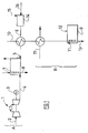
- the invention is illustrated by the figure 1 .
- the illustrated industrial site comprises a cogeneration unit A and a steam production unit B.
- the gas turbine 1 is fed with a fuel 2. It produces mechanical or electrical energy 3 and 4.
- These combustion fumes 4 are introduced into a heat recovery unit 5 to enhance their calories.
- the heat recovery unit 5 is fed with water 6, this water is heated by combustion of a fuel 7 and the oxygen remaining in the combustion fumes 4.
- This heat recovery unit 5 produces steam 8.
- the water 6 is obtained by heating cold water 16 in a degasser 14 supplied with water vapor 15.
- the steam production unit B comprises a boiler 9 for heating water 12 by combustion of fuel 11 with air 10.
- Boiler 9 produces steam 13.
- Air 10 is preheated by heat exchange with water 6 of the unit heat recovery 5, then by heat exchange with water vapor 17.
- the water vapors 15 and 17 used for heating the water 16 of the heat recovery unit 5 and the air 10 of the boiler are preferably low or medium pressure vapors derived from the high pressure vapors 8 and 13 produced by the heat recovery unit 5 and the boiler 9.
- the method according to the invention makes it possible to reduce the consumption of water vapor necessary for heating the air of the steam production boiler by recovering the heat from the water intended to supply the heat recovery unit. At the same time, only a slight decrease in steam production by the heat recovery unit was observed. Overall, the process according to the invention has made it possible to save 10% of the steam used for the process of the prior art without heat exchange between the air of the steam production unit and the water which feeds the heat recovery unit of the cogeneration unit.
- the invention has been implemented on an industrial site reproducing the scheme of the figure 1 .
- the temperature of the water to be introduced into the heat recovery unit was 148 ° C and the temperature of the air to be introduced into the steam unit was 10 ° C. Heat exchange between these two fluids was carried out so as to bring the temperature of the water to be introduced into the heat recovery unit at 68 ° C. Due to the preheating of the air to be introduced into the steam generating unit, it has been possible to save 10 t / h of water vapor of 4 bar pressure for the heating of this air. In return, the heat recovery unit of the cogeneration unit reduced its production of high pressure steam only from 69.7 t / h to 69 t / h.
Landscapes
- Engineering & Computer Science (AREA)
- Mechanical Engineering (AREA)
- General Engineering & Computer Science (AREA)
- Chemical & Material Sciences (AREA)
- Combustion & Propulsion (AREA)
- Thermal Sciences (AREA)
- Physics & Mathematics (AREA)
- Sustainable Development (AREA)
- Sustainable Energy (AREA)
- Life Sciences & Earth Sciences (AREA)
- Air Supply (AREA)
- Engine Equipment That Uses Special Cycles (AREA)
- Heat Treatment Of Water, Waste Water Or Sewage (AREA)
Abstract
Description
- La présente invention concerne un procédé d'optimisation énergétique d'un site de production d'énergie électrique et de chaleur.
- Les grands sites industriels utilisent les commodités de base que sont, d'une part, l'énergie mécanique ou électrique et, d'autre part, la vapeur ou l'eau chaude. Sur de nombreux sites, ces commodités sont produites sur place dans des unités voisines de cogénération et de production de vapeur ou d'eau chaude.
- Un but de la présente invention est de proposer l'intégration d'un train de cogénération avec chaudière de récupération de chaleur et d'une unité de production de vapeur voisine de manière à optimiser le rendement énergétique global des deux unités.
- Dans ce but, l'invention concerne un procédé de production d'énergie, de chaleur et de vapeur d'eau mettant en oeuvre:
- une unité de cogénération comprenant :
- une turbine à gaz produisant de l'énergie et des gaz de combustion, et
- une unité de récupération de chaleur alimentée en eau et mettant en oeuvre le chauffage de ladite eau par récupération de la chaleur des gaz de combustion de la turbine à gaz,
- une unité de production de vapeur mettant en oeuvre le chauffage d'eau par combustion d'un combustible et d'air,
- L'invention concerne donc un procédé mis en oeuvre sur un site industriel comprenant à la fois une unité de cogénération et une unité de production de vapeur.
- L'unité de cogénération comprend une turbine à gaz produisant de l'énergie mécanique ou électrique par détente de gaz de combustion. La chaleur de ces gaz de combustion est récupérée dans une unité de récupération de chaleur destinée à produire de la vapeur d'eau ou de l'eau chaude. Cette unité de récupération de chaleur est généralement une chaudière dans laquelle la chaleur des gaz de combustion de la turbine à gaz chauffe l'eau introduite dans la chaudière. Les gaz de combustion de la turbine peuvent également être utilisés comme comburant s'ils contiennent encore de l'oxygène et si un combustible est introduit dans l'unité de récupération de chaleur ; on parle alors de post-combustion. Généralement, l'unité de récupération de chaleur est alimentée par une eau déjà chaude ; par "eau chaude", on entend une eau présentant une température d'au moins 105°C.
- L'unité de production de vapeur est habituellement une chaudière dans laquelle un combustible est brûlé en présence d'air pour dégager de la chaleur. Cette chaleur chauffe de l'eau jusqu'à obtenir de la vapeur.
- Selon l'invention, l'air introduit dans la chaudière de l'unité de production de vapeur est chauffé préalablement à son introduction dans la chaudière par échange de chaleur avec l'eau destinée à alimenter l'unité de récupération de chaleur de l'unité de cogénération. De préférence, la température de l'eau de l'unité de récupération de chaleur de l'unité de cogénération est supérieure d'au moins 20°C, encore plus préférentiellement d'au moins 30°C, voire d'au moins 50°C, à celle de l'air de l'unité de production de vapeur à préchauffer.
- L'invention peut être mise en oeuvre avec les préférences suivantes :
- l'eau qui alimente l'unité de récupération de chaleur est chauffée par de la vapeur d'eau.
- l'eau qui alimente l'unité de récupération de chaleur est chauffée par de la vapeur d'eau dérivée de la vapeur produite par l'unité de production de vapeur et/ou par l'unité de récupération de chaleur de l'unité de cogénération, avantageusement par de la vapeur de basse pression produite par ces unités.
- l'eau qui alimente l'unité de récupération de chaleur est chauffée par de la vapeur d'eau au moyen d'un dégazeur,
- l'eau qui alimente l'unité de récupération de chaleur est chauffée au moyen d'un dégazeur par de la vapeur d'eau dérivée de l'unité de production de vapeur d'eau et/ou de l'unité de récupération de chaleur de l'unité de cogénération. Le dégazeur permet de mettre en contact l'eau à préchauffer avec de la vapeur d'eau de manière à préchauffer l'eau et simultanément éliminer l'oxygène dissous dans cette eau.
- l'air introduit dans l'unité de production de vapeur est également chauffé en partie par échange de chaleur avec de la vapeur d'eau produite par ladite unité de production de vapeur et/ou par l'unité de récupération de chaleur de l'unité de cogénération. De préférence, l'air est chauffé au moyen de vapeur de basse ou moyenne pression. Il est également préférable que ce chauffage de l'air qui alimente la chaudière de l'unité de production de vapeur par de la vapeur soit réalisé après que l'air de l'unité de production de vapeur ait été préchauffé par échange de chaleur avec l'eau qui alimente l'unité de récupération de chaleur de l'unité de cogénération.
- L'invention est illustrée par la
figure 1 . Le site industriel illustré comprend une unité de cogénération A et une unité de production de vapeur B. Dans l'unité de cogénération A, la turbine à gaz 1 est alimentée par un combustible 2. Elle produit de l'énergie mécanique ou électrique 3 et des fumées de combustion chaudes 4. Ces fumées de combustion 4 sont introduites dans une unité de récupération de chaleur 5 pour valoriser leurs calories. L'unité de récupération de chaleur 5 est alimentée par de l'eau 6, cette eau est chauffée par combustion d'un combustible 7 et de l'oxygène restant dans les fumées de combustion 4. Cette unité de récupération de chaleur 5 produit de la vapeur 8. L'eau 6 est obtenue par chauffage d'eau froide 16 dans un dégazeur 14 alimenté en vapeur d'eau 15. L'unité de production de vapeur B comprend une chaudière 9 pour chauffer de l'eau 12 par combustion d'un combustible 11 avec de l'air 10. La chaudière 9 produit de la vapeur 13. L'air 10 est préalablement chauffé par échange de chaleur avec l'eau 6 de l'unité de récupération de chaleur 5, puis par échange de chaleur avec de la vapeur d'eau 17. - Les vapeurs d'eau 15 et 17 utilisées pour le chauffage de l'eau 16 de l'unité de récupération de chaleur 5 et de l'air 10 de la chaudière sont de préférence des vapeurs de basse ou moyenne pression dérivées des vapeurs haute pression 8 et 13 produites par l'unité de récupération de chaleur 5 et par la chaudière 9.
- Le procédé selon l'invention permet de réduire la consommation de vapeur d'eau nécessaire au chauffage de l'air de la chaudière de production de vapeur en récupérant la chaleur de l'eau destinée à alimenter l'unité de récupération de chaleur. Simultanément, il n'a été observé qu'une très légère baisse de production de vapeur par l'unité de récupération de chaleur. Globalement, le procédé selon l'invention a permis de faire l'économie de 10 % de la vapeur utilisée pour le procédé de l'art antérieur sans échange de chaleur entre l'air de l'unité de production de vapeur et l'eau qui alimente l'unité de récupération de chaleur de l'unité de cogénération.
- L'invention a été mise en oeuvre sur un site industriel reproduisant le schéma de la
figure 1 . La température de l'eau destinée à être introduite dans l'unité de récupération de chaleur était de 148°C et la température de l'air destiné à être introduit dans l'unité de production de vapeur était de 10°C. Un échange de chaleur entre ces deux fluides a été mis en oeuvre de manière à amener la température de l'eau destinée à être introduite dans l'unité de récupération de chaleur à 68°C. Du fait du préchauffage de l'air destiné à être introduit dans l'unité de production de vapeur, il a été possible d'économiser 10 t/h de vapeur d'eau de 4 bar de pression pour le chauffage de cet air. En contrepartie, l'unité de récupération de chaleur de l'unité de cogénération a baissé sa production de vapeur d'eau à haute pression seulement de 69,7 t/h à 69 t/h.
Claims (8)
- Procédé de production d'énergie, de chaleur et de vapeur d'eau mettant en oeuvre :- une unité de cogénération (A) comprenant :. une turbine à gaz (1) produisant de l'énergie (3) et des gaz de combustion (4), et. une unité de récupération de chaleur (5) alimentée en eau (6) et mettant en oeuvre le chauffage de ladite eau (6) par récupération de la chaleur des gaz de combustion (4) de la turbine à gaz,- une unité de production de vapeur (B) mettant en oeuvre le chauffage d'eau (12) par combustion d'un combustible (11) et d'air (10),et dans lequel l'air (10) de l'unité de production de vapeur (B) est préchauffé au moins en partie par échange de chaleur avec l'eau (6) qui alimente l'unité de récupération de chaleur (5) de l'unité de cogénération (A).
- Procédé selon la revendication précédente, caractérisé en ce que la température de l'eau (6) de l'unité de récupération de chaleur (5) de l'unité de cogénération (A) est supérieure d'au moins 20°C à celle de l'air (10) de l'unité de production de vapeur (B) à préchauffer.
- Procédé selon la revendication 1 ou 2, caractérisé en ce que la température de l'eau (6) de l'unité de récupération de chaleur (5) de l'unité de cogénération (A) est supérieure d'au moins 30°C à celle de l'air (10) de l'unité de production de vapeur (B) à préchauffer.
- Procédé selon l'une des revendications précédentes, caractérisé en ce que l'eau (6) qui alimente l'unité de récupération de chaleur (5) est chauffée par de la vapeur d'eau (15).
- Procédé selon la revendication précédente, caractérisé en ce que l'eau (6) qui alimente l'unité de récupération de chaleur est chauffée par de la vapeur d'eau (15) dérivée de la vapeur d'eau (13, 8) produite par l'unité de production de vapeur (B) et/ou par l'unité de récupération de chaleur (5) de l'unité de cogénération (A).
- Procédé selon la revendication 4 ou 5, caractérisé en ce que l'eau (6) qui alimente l'unité de récupération de chaleur (5) est chauffée au moyen d'un dégazeur (14) par de la vapeur d'eau (15).
- Procédé selon l'une des revendications précédentes, caractérisé en ce que l'air (10) qui alimente la chaudière (9) de l'unité de production de vapeur (B) est chauffé en partie par échange de chaleur avec de la vapeur (17) produite par ladite unité de production de vapeur (B) et/ou par l'unité de récupération de chaleur (5) de l'unité de cogénération (A).
- Procédé selon la revendication 7, caractérisé en ce que le chauffage de l'air (10) qui alimente la chaudière (9) de l'unité de production de vapeur (B) par de la vapeur est réalisé après que l'air (10) de l'unité de production de vapeur (B) ait été préchauffé par échange de chaleur avec l'eau (6) qui alimente l'unité de récupération de chaleur (5) de l'unité de cogénération (A).
Applications Claiming Priority (1)
| Application Number | Priority Date | Filing Date | Title |
|---|---|---|---|
| FR0752874A FR2911912B1 (fr) | 2007-01-25 | 2007-01-25 | Procede d'optimisation energetique d'un site de production d'energie et de vapeur d'eau. |
Publications (2)
| Publication Number | Publication Date |
|---|---|
| EP1950391A1 true EP1950391A1 (fr) | 2008-07-30 |
| EP1950391B1 EP1950391B1 (fr) | 2010-03-10 |
Family
ID=38379592
Family Applications (1)
| Application Number | Title | Priority Date | Filing Date |
|---|---|---|---|
| EP08150318A Active EP1950391B1 (fr) | 2007-01-25 | 2008-01-16 | Procédé d'optimisation énergétique d'un site de production d'énergie et de vapeur d'eau |
Country Status (5)
| Country | Link |
|---|---|
| US (1) | US8056316B2 (fr) |
| EP (1) | EP1950391B1 (fr) |
| AT (1) | ATE460578T1 (fr) |
| DE (1) | DE602008000764D1 (fr) |
| FR (1) | FR2911912B1 (fr) |
Cited By (1)
| Publication number | Priority date | Publication date | Assignee | Title |
|---|---|---|---|---|
| EP2839221A4 (fr) * | 2012-04-04 | 2016-03-23 | Viking Heat Engines As | Station de chauffage et d'alimentation électrique combinés |
Families Citing this family (7)
| Publication number | Priority date | Publication date | Assignee | Title |
|---|---|---|---|---|
| US9435534B2 (en) * | 2009-08-31 | 2016-09-06 | Holistic Engineering Inc | Energy-recovery system for a production plant |
| US8161724B2 (en) * | 2010-03-31 | 2012-04-24 | Eif Nte Hybrid Intellectual Property Holding Company, Llc | Hybrid biomass process with reheat cycle |
| US8596034B2 (en) * | 2010-03-31 | 2013-12-03 | Eif Nte Hybrid Intellectual Property Holding Company, Llc | Hybrid power generation cycle systems and methods |
| US8495878B1 (en) | 2012-04-09 | 2013-07-30 | Eif Nte Hybrid Intellectual Property Holding Company, Llc | Feedwater heating hybrid power generation |
| US9285847B2 (en) | 2012-06-14 | 2016-03-15 | Pac, Llc | Cogeneration system and process for determining whether to use cogeneration |
| US10075115B2 (en) | 2012-06-14 | 2018-09-11 | Pac, Llc | Cogeneration system configured to be installed into an existing boiler plant/emergency generator installation and process for cogeneration |
| EP3203149B1 (fr) * | 2016-02-03 | 2018-09-05 | L'air Liquide, Societe Anonyme Pour L'etude Et L'exploitation Des Procedes Georges Claude | Processus et installation de cogénération à cycle combiné |
Citations (5)
| Publication number | Priority date | Publication date | Assignee | Title |
|---|---|---|---|---|
| US2471755A (en) | 1944-01-05 | 1949-05-31 | Oerlikon Maschf | Steam-air-thermal power plant |
| GB899904A (en) | 1960-04-23 | 1962-06-27 | Babcock & Wilcox Ltd | Improvements in power plants |
| US3118429A (en) | 1961-11-08 | 1964-01-21 | Combustion Eng | Power plant in which single cycle gas turbine operates in parallel with direct fired steam generator |
| US4462206A (en) | 1981-06-10 | 1984-07-31 | Sulzer Brothers Limited | Gas turbine-steam power plant |
| US20060260290A1 (en) * | 2003-03-18 | 2006-11-23 | Ashok Rao | Humid air turbine cycle with carbon dioxide recovery |
Family Cites Families (13)
| Publication number | Priority date | Publication date | Assignee | Title |
|---|---|---|---|---|
| DE2005722C3 (de) * | 1970-02-07 | 1973-01-04 | Steag Ag, 4300 Essen | Anfahrschaltung einer Gasturbinenanlage |
| US5634329A (en) * | 1992-04-30 | 1997-06-03 | Abb Carbon Ab | Method of maintaining a nominal working temperature of flue gases in a PFBC power plant |
| US5285629A (en) * | 1992-11-25 | 1994-02-15 | Pyropower Corporation | Circulating fluidized bed power plant with turbine fueled with sulfur containing fuel and using CFB to control emissions |
| WO1994024428A1 (fr) * | 1993-04-20 | 1994-10-27 | Humphries, James, J., Jr. | Production de puissance electrique |
| US5794431A (en) * | 1993-07-14 | 1998-08-18 | Hitachi, Ltd. | Exhaust recirculation type combined plant |
| JP3681434B2 (ja) * | 1995-04-25 | 2005-08-10 | 重昭 木村 | コージェネレーション装置およびコンバインドサイクル発電装置 |
| US5623822A (en) * | 1995-05-23 | 1997-04-29 | Montenay International Corp. | Method of operating a waste-to-energy plant having a waste boiler and gas turbine cycle |
| US5666801A (en) * | 1995-09-01 | 1997-09-16 | Rohrer; John W. | Combined cycle power plant with integrated CFB devolatilizer and CFB boiler |
| US6145295A (en) * | 1998-11-23 | 2000-11-14 | Siemens Westinghouse Power Corporation | Combined cycle power plant having improved cooling and method of operation thereof |
| JP4225679B2 (ja) * | 2000-11-17 | 2009-02-18 | 株式会社東芝 | コンバインドサイクル発電プラント |
| EP1432889B1 (fr) * | 2001-10-01 | 2006-07-12 | Alstom Technology Ltd | Procede et dispositif permettant de demarrer des centrales thermiques a gaz exemptes d'emissions |
| US7284363B2 (en) * | 2004-06-16 | 2007-10-23 | Honeywell International, Inc. | Method of power generation for airborne vehicles |
| JP4581563B2 (ja) * | 2004-08-31 | 2010-11-17 | 株式会社日立製作所 | コンバインドサイクル発電設備,蒸気火力発電設備 |
-
2007
- 2007-01-25 FR FR0752874A patent/FR2911912B1/fr not_active Expired - Fee Related
-
2008
- 2008-01-16 AT AT08150318T patent/ATE460578T1/de not_active IP Right Cessation
- 2008-01-16 EP EP08150318A patent/EP1950391B1/fr active Active
- 2008-01-16 DE DE602008000764T patent/DE602008000764D1/de active Active
- 2008-01-23 US US12/018,328 patent/US8056316B2/en not_active Expired - Fee Related
Patent Citations (5)
| Publication number | Priority date | Publication date | Assignee | Title |
|---|---|---|---|---|
| US2471755A (en) | 1944-01-05 | 1949-05-31 | Oerlikon Maschf | Steam-air-thermal power plant |
| GB899904A (en) | 1960-04-23 | 1962-06-27 | Babcock & Wilcox Ltd | Improvements in power plants |
| US3118429A (en) | 1961-11-08 | 1964-01-21 | Combustion Eng | Power plant in which single cycle gas turbine operates in parallel with direct fired steam generator |
| US4462206A (en) | 1981-06-10 | 1984-07-31 | Sulzer Brothers Limited | Gas turbine-steam power plant |
| US20060260290A1 (en) * | 2003-03-18 | 2006-11-23 | Ashok Rao | Humid air turbine cycle with carbon dioxide recovery |
Cited By (1)
| Publication number | Priority date | Publication date | Assignee | Title |
|---|---|---|---|---|
| EP2839221A4 (fr) * | 2012-04-04 | 2016-03-23 | Viking Heat Engines As | Station de chauffage et d'alimentation électrique combinés |
Also Published As
| Publication number | Publication date |
|---|---|
| DE602008000764D1 (de) | 2010-04-22 |
| US8056316B2 (en) | 2011-11-15 |
| EP1950391B1 (fr) | 2010-03-10 |
| ATE460578T1 (de) | 2010-03-15 |
| FR2911912B1 (fr) | 2009-03-06 |
| FR2911912A1 (fr) | 2008-08-01 |
| US20080178604A1 (en) | 2008-07-31 |
Similar Documents
| Publication | Publication Date | Title |
|---|---|---|
| EP1950391A1 (fr) | Procédé d'optimisation énergétique d'un site de production d'énergie et de vapeur d'eau | |
| CA2619681C (fr) | Prechauffage du combustible et du comburant d'oxybruleurs a partir d'installations de prechauffage d'air de combustion | |
| NO20005114L (no) | FremgangsmÕte for Õ generere kraft ved hjelp av en avansert, termokjemisk rekuperasjonssyklus | |
| RU2010101227A (ru) | Устройство и способ риформинга | |
| EA201071125A1 (ru) | Способ и устройство для получения минерального расплава | |
| WO2010001217A4 (fr) | Centrale électrique à sources chaudes multiples | |
| EP2281164A1 (fr) | Procédé de fabrication de clinker de ciment et installation de fabrication de clinker de ciment. | |
| KR20160108343A (ko) | 에너지 회수가 최적화된 연소 방법 및 설비 | |
| EP3844371B1 (fr) | Système de génération d'énergie dans un fluide de travail à partir d'hydrogène et d'oxygène et procédé de fonctionnement de ce système | |
| WO2014207944A1 (fr) | Système de combustion | |
| RU2010108334A (ru) | Способ эксплуатации установки для сжигания и установка для сжигания | |
| CN104531226A (zh) | 一种用于工业窑炉的生物质气化燃烧供热方法 | |
| RU2011124511A (ru) | Способ эксплуатации установки для производства биоэтанола | |
| WO2014096613A1 (fr) | Recuperation energetique des fumees d'un four de fusion au moyen d'une turbine a gaz et des échangeurs de chaleur | |
| WO2010133193A3 (fr) | Centrale et procédé d'exploitation de cette centrale | |
| AR067578A1 (es) | Un calentador de combustion no inflamable, sistema calentador, un metodo para iniciar el sistema calentador y metodo para controlar la temperatura del sistema calentador. | |
| EP2067935B1 (fr) | Procédé d'optimisation énergétique d'un site comprenant une cogénération et une centrale thermique | |
| JP2005098198A (ja) | 廃棄物処理炉の高効率発電システム | |
| CN218064859U (zh) | 一种电煅无烟煤生产烟气余热利用系统 | |
| JP4301622B2 (ja) | 高効率発電方法及び高効率発電システム | |
| CN101012925A (zh) | 烃燃料与水或水蒸汽燃烧产生的废气回收后再循环燃烧利用的方法 | |
| EP4030099A3 (fr) | Procédé et dispositif de récupération d'énergie après la combustion de matériau combustible solide | |
| NO20100085L (no) | Fremgangsmate og anlegg for kombinert produksjon av elektrisk energi og vann | |
| RU2005137597A (ru) | Способ работы тепловой электрической станции | |
| TW200813371A (en) | Manufacturing method of thermal cracking water into oxyhydrogen flame |
Legal Events
| Date | Code | Title | Description |
|---|---|---|---|
| PUAI | Public reference made under article 153(3) epc to a published international application that has entered the european phase |
Free format text: ORIGINAL CODE: 0009012 |
|
| AK | Designated contracting states |
Kind code of ref document: A1 Designated state(s): AT BE BG CH CY CZ DE DK EE ES FI FR GB GR HR HU IE IS IT LI LT LU LV MC MT NL NO PL PT RO SE SI SK TR |
|
| AX | Request for extension of the european patent |
Extension state: AL BA MK RS |
|
| 17P | Request for examination filed |
Effective date: 20090130 |
|
| AKX | Designation fees paid |
Designated state(s): AT BE BG CH CY CZ DE DK EE ES FI FR GB GR HR HU IE IS IT LI LT LU LV MC MT NL NO PL PT RO SE SI SK TR |
|
| GRAP | Despatch of communication of intention to grant a patent |
Free format text: ORIGINAL CODE: EPIDOSNIGR1 |
|
| GRAS | Grant fee paid |
Free format text: ORIGINAL CODE: EPIDOSNIGR3 |
|
| GRAA | (expected) grant |
Free format text: ORIGINAL CODE: 0009210 |
|
| AK | Designated contracting states |
Kind code of ref document: B1 Designated state(s): AT BE BG CH CY CZ DE DK EE ES FI FR GB GR HR HU IE IS IT LI LT LU LV MC MT NL NO PL PT RO SE SI SK TR |
|
| REG | Reference to a national code |
Ref country code: GB Ref legal event code: FG4D Free format text: NOT ENGLISH |
|
| REG | Reference to a national code |
Ref country code: CH Ref legal event code: EP |
|
| REG | Reference to a national code |
Ref country code: IE Ref legal event code: FG4D |
|
| REF | Corresponds to: |
Ref document number: 602008000764 Country of ref document: DE Date of ref document: 20100422 Kind code of ref document: P |
|
| REG | Reference to a national code |
Ref country code: NL Ref legal event code: T3 |
|
| PG25 | Lapsed in a contracting state [announced via postgrant information from national office to epo] |
Ref country code: LT Free format text: LAPSE BECAUSE OF FAILURE TO SUBMIT A TRANSLATION OF THE DESCRIPTION OR TO PAY THE FEE WITHIN THE PRESCRIBED TIME-LIMIT Effective date: 20100310 Ref country code: HR Free format text: LAPSE BECAUSE OF FAILURE TO SUBMIT A TRANSLATION OF THE DESCRIPTION OR TO PAY THE FEE WITHIN THE PRESCRIBED TIME-LIMIT Effective date: 20100310 Ref country code: NO Free format text: LAPSE BECAUSE OF FAILURE TO SUBMIT A TRANSLATION OF THE DESCRIPTION OR TO PAY THE FEE WITHIN THE PRESCRIBED TIME-LIMIT Effective date: 20100610 |
|
| LTIE | Lt: invalidation of european patent or patent extension |
Effective date: 20100310 |
|
| PG25 | Lapsed in a contracting state [announced via postgrant information from national office to epo] |
Ref country code: PL Free format text: LAPSE BECAUSE OF FAILURE TO SUBMIT A TRANSLATION OF THE DESCRIPTION OR TO PAY THE FEE WITHIN THE PRESCRIBED TIME-LIMIT Effective date: 20100310 Ref country code: AT Free format text: LAPSE BECAUSE OF FAILURE TO SUBMIT A TRANSLATION OF THE DESCRIPTION OR TO PAY THE FEE WITHIN THE PRESCRIBED TIME-LIMIT Effective date: 20100310 Ref country code: LV Free format text: LAPSE BECAUSE OF FAILURE TO SUBMIT A TRANSLATION OF THE DESCRIPTION OR TO PAY THE FEE WITHIN THE PRESCRIBED TIME-LIMIT Effective date: 20100310 Ref country code: FI Free format text: LAPSE BECAUSE OF FAILURE TO SUBMIT A TRANSLATION OF THE DESCRIPTION OR TO PAY THE FEE WITHIN THE PRESCRIBED TIME-LIMIT Effective date: 20100310 Ref country code: SI Free format text: LAPSE BECAUSE OF FAILURE TO SUBMIT A TRANSLATION OF THE DESCRIPTION OR TO PAY THE FEE WITHIN THE PRESCRIBED TIME-LIMIT Effective date: 20100310 |
|
| REG | Reference to a national code |
Ref country code: IE Ref legal event code: FD4D |
|
| PG25 | Lapsed in a contracting state [announced via postgrant information from national office to epo] |
Ref country code: ES Free format text: LAPSE BECAUSE OF FAILURE TO SUBMIT A TRANSLATION OF THE DESCRIPTION OR TO PAY THE FEE WITHIN THE PRESCRIBED TIME-LIMIT Effective date: 20100621 Ref country code: EE Free format text: LAPSE BECAUSE OF FAILURE TO SUBMIT A TRANSLATION OF THE DESCRIPTION OR TO PAY THE FEE WITHIN THE PRESCRIBED TIME-LIMIT Effective date: 20100310 Ref country code: CY Free format text: LAPSE BECAUSE OF FAILURE TO SUBMIT A TRANSLATION OF THE DESCRIPTION OR TO PAY THE FEE WITHIN THE PRESCRIBED TIME-LIMIT Effective date: 20100310 Ref country code: GR Free format text: LAPSE BECAUSE OF FAILURE TO SUBMIT A TRANSLATION OF THE DESCRIPTION OR TO PAY THE FEE WITHIN THE PRESCRIBED TIME-LIMIT Effective date: 20100611 Ref country code: RO Free format text: LAPSE BECAUSE OF FAILURE TO SUBMIT A TRANSLATION OF THE DESCRIPTION OR TO PAY THE FEE WITHIN THE PRESCRIBED TIME-LIMIT Effective date: 20100310 Ref country code: SE Free format text: LAPSE BECAUSE OF FAILURE TO SUBMIT A TRANSLATION OF THE DESCRIPTION OR TO PAY THE FEE WITHIN THE PRESCRIBED TIME-LIMIT Effective date: 20100310 |
|
| PG25 | Lapsed in a contracting state [announced via postgrant information from national office to epo] |
Ref country code: SK Free format text: LAPSE BECAUSE OF FAILURE TO SUBMIT A TRANSLATION OF THE DESCRIPTION OR TO PAY THE FEE WITHIN THE PRESCRIBED TIME-LIMIT Effective date: 20100310 Ref country code: BG Free format text: LAPSE BECAUSE OF FAILURE TO SUBMIT A TRANSLATION OF THE DESCRIPTION OR TO PAY THE FEE WITHIN THE PRESCRIBED TIME-LIMIT Effective date: 20100610 Ref country code: CZ Free format text: LAPSE BECAUSE OF FAILURE TO SUBMIT A TRANSLATION OF THE DESCRIPTION OR TO PAY THE FEE WITHIN THE PRESCRIBED TIME-LIMIT Effective date: 20100310 Ref country code: IS Free format text: LAPSE BECAUSE OF FAILURE TO SUBMIT A TRANSLATION OF THE DESCRIPTION OR TO PAY THE FEE WITHIN THE PRESCRIBED TIME-LIMIT Effective date: 20100710 |
|
| PLBE | No opposition filed within time limit |
Free format text: ORIGINAL CODE: 0009261 |
|
| STAA | Information on the status of an ep patent application or granted ep patent |
Free format text: STATUS: NO OPPOSITION FILED WITHIN TIME LIMIT |
|
| PG25 | Lapsed in a contracting state [announced via postgrant information from national office to epo] |
Ref country code: IE Free format text: LAPSE BECAUSE OF FAILURE TO SUBMIT A TRANSLATION OF THE DESCRIPTION OR TO PAY THE FEE WITHIN THE PRESCRIBED TIME-LIMIT Effective date: 20100310 Ref country code: DK Free format text: LAPSE BECAUSE OF FAILURE TO SUBMIT A TRANSLATION OF THE DESCRIPTION OR TO PAY THE FEE WITHIN THE PRESCRIBED TIME-LIMIT Effective date: 20100310 |
|
| 26N | No opposition filed |
Effective date: 20101213 |
|
| PG25 | Lapsed in a contracting state [announced via postgrant information from national office to epo] |
Ref country code: IT Free format text: LAPSE BECAUSE OF FAILURE TO SUBMIT A TRANSLATION OF THE DESCRIPTION OR TO PAY THE FEE WITHIN THE PRESCRIBED TIME-LIMIT Effective date: 20100310 |
|
| PG25 | Lapsed in a contracting state [announced via postgrant information from national office to epo] |
Ref country code: MC Free format text: LAPSE BECAUSE OF NON-PAYMENT OF DUE FEES Effective date: 20110131 |
|
| PG25 | Lapsed in a contracting state [announced via postgrant information from national office to epo] |
Ref country code: MT Free format text: LAPSE BECAUSE OF FAILURE TO SUBMIT A TRANSLATION OF THE DESCRIPTION OR TO PAY THE FEE WITHIN THE PRESCRIBED TIME-LIMIT Effective date: 20100310 |
|
| REG | Reference to a national code |
Ref country code: CH Ref legal event code: PL |
|
| GBPC | Gb: european patent ceased through non-payment of renewal fee |
Effective date: 20120116 |
|
| PG25 | Lapsed in a contracting state [announced via postgrant information from national office to epo] |
Ref country code: CH Free format text: LAPSE BECAUSE OF NON-PAYMENT OF DUE FEES Effective date: 20120131 Ref country code: GB Free format text: LAPSE BECAUSE OF NON-PAYMENT OF DUE FEES Effective date: 20120116 Ref country code: LI Free format text: LAPSE BECAUSE OF NON-PAYMENT OF DUE FEES Effective date: 20120131 |
|
| PG25 | Lapsed in a contracting state [announced via postgrant information from national office to epo] |
Ref country code: LU Free format text: LAPSE BECAUSE OF NON-PAYMENT OF DUE FEES Effective date: 20110116 |
|
| PG25 | Lapsed in a contracting state [announced via postgrant information from national office to epo] |
Ref country code: PT Free format text: LAPSE BECAUSE OF NON-PAYMENT OF DUE FEES Effective date: 20100310 |
|
| PG25 | Lapsed in a contracting state [announced via postgrant information from national office to epo] |
Ref country code: TR Free format text: LAPSE BECAUSE OF FAILURE TO SUBMIT A TRANSLATION OF THE DESCRIPTION OR TO PAY THE FEE WITHIN THE PRESCRIBED TIME-LIMIT Effective date: 20100310 |
|
| PG25 | Lapsed in a contracting state [announced via postgrant information from national office to epo] |
Ref country code: HU Free format text: LAPSE BECAUSE OF FAILURE TO SUBMIT A TRANSLATION OF THE DESCRIPTION OR TO PAY THE FEE WITHIN THE PRESCRIBED TIME-LIMIT Effective date: 20100310 |
|
| REG | Reference to a national code |
Ref country code: FR Ref legal event code: PLFP Year of fee payment: 9 |
|
| REG | Reference to a national code |
Ref country code: FR Ref legal event code: PLFP Year of fee payment: 10 |
|
| REG | Reference to a national code |
Ref country code: FR Ref legal event code: PLFP Year of fee payment: 11 |
|
| PGFP | Annual fee paid to national office [announced via postgrant information from national office to epo] |
Ref country code: DE Payment date: 20180122 Year of fee payment: 11 |
|
| PGFP | Annual fee paid to national office [announced via postgrant information from national office to epo] |
Ref country code: BE Payment date: 20180119 Year of fee payment: 11 |
|
| REG | Reference to a national code |
Ref country code: DE Ref legal event code: R119 Ref document number: 602008000764 Country of ref document: DE |
|
| REG | Reference to a national code |
Ref country code: BE Ref legal event code: MM Effective date: 20190131 |
|
| PG25 | Lapsed in a contracting state [announced via postgrant information from national office to epo] |
Ref country code: DE Free format text: LAPSE BECAUSE OF NON-PAYMENT OF DUE FEES Effective date: 20190801 |
|
| PG25 | Lapsed in a contracting state [announced via postgrant information from national office to epo] |
Ref country code: BE Free format text: LAPSE BECAUSE OF NON-PAYMENT OF DUE FEES Effective date: 20190131 |
|
| PGFP | Annual fee paid to national office [announced via postgrant information from national office to epo] |
Ref country code: NL Payment date: 20260121 Year of fee payment: 19 |
|
| PGFP | Annual fee paid to national office [announced via postgrant information from national office to epo] |
Ref country code: FR Payment date: 20260123 Year of fee payment: 19 |