EP1950370A1 - Dispositif de verrouillage pour portes, volets et similaires - Google Patents
Dispositif de verrouillage pour portes, volets et similaires Download PDFInfo
- Publication number
- EP1950370A1 EP1950370A1 EP08001155A EP08001155A EP1950370A1 EP 1950370 A1 EP1950370 A1 EP 1950370A1 EP 08001155 A EP08001155 A EP 08001155A EP 08001155 A EP08001155 A EP 08001155A EP 1950370 A1 EP1950370 A1 EP 1950370A1
- Authority
- EP
- European Patent Office
- Prior art keywords
- shutter
- magnets
- coupling element
- handling means
- magnet
- Prior art date
- Legal status (The legal status is an assumption and is not a legal conclusion. Google has not performed a legal analysis and makes no representation as to the accuracy of the status listed.)
- Withdrawn
Links
Images


Classifications
-
- E—FIXED CONSTRUCTIONS
- E05—LOCKS; KEYS; WINDOW OR DOOR FITTINGS; SAFES
- E05C—BOLTS OR FASTENING DEVICES FOR WINGS, SPECIALLY FOR DOORS OR WINDOWS
- E05C17/00—Devices for holding wings open; Devices for limiting opening of wings or for holding wings open by a movable member extending between frame and wing; Braking devices, stops or buffers, combined therewith
- E05C17/56—Devices for holding wings open; Devices for limiting opening of wings or for holding wings open by a movable member extending between frame and wing; Braking devices, stops or buffers, combined therewith by magnetic or electromagnetic attraction or operated by electric or electromagnetic means
-
- E—FIXED CONSTRUCTIONS
- E05—LOCKS; KEYS; WINDOW OR DOOR FITTINGS; SAFES
- E05B—LOCKS; ACCESSORIES THEREFOR; HANDCUFFS
- E05B47/00—Operating or controlling locks or other fastening devices by electric or magnetic means
- E05B47/0038—Operating or controlling locks or other fastening devices by electric or magnetic means using permanent magnets
- E05B47/004—Operating or controlling locks or other fastening devices by electric or magnetic means using permanent magnets the magnets acting directly on the bolt
-
- E—FIXED CONSTRUCTIONS
- E05—LOCKS; KEYS; WINDOW OR DOOR FITTINGS; SAFES
- E05B—LOCKS; ACCESSORIES THEREFOR; HANDCUFFS
- E05B53/00—Operation or control of locks by mechanical transmissions, e.g. from a distance
-
- E—FIXED CONSTRUCTIONS
- E05—LOCKS; KEYS; WINDOW OR DOOR FITTINGS; SAFES
- E05B—LOCKS; ACCESSORIES THEREFOR; HANDCUFFS
- E05B53/00—Operation or control of locks by mechanical transmissions, e.g. from a distance
- E05B53/003—Operation or control of locks by mechanical transmissions, e.g. from a distance flexible
-
- E—FIXED CONSTRUCTIONS
- E05—LOCKS; KEYS; WINDOW OR DOOR FITTINGS; SAFES
- E05C—BOLTS OR FASTENING DEVICES FOR WINGS, SPECIALLY FOR DOORS OR WINDOWS
- E05C17/00—Devices for holding wings open; Devices for limiting opening of wings or for holding wings open by a movable member extending between frame and wing; Braking devices, stops or buffers, combined therewith
- E05C17/02—Devices for holding wings open; Devices for limiting opening of wings or for holding wings open by a movable member extending between frame and wing; Braking devices, stops or buffers, combined therewith by mechanical means
- E05C17/46—Devices for holding wings open; Devices for limiting opening of wings or for holding wings open by a movable member extending between frame and wing; Braking devices, stops or buffers, combined therewith by mechanical means in which the wing or a member fixed thereon is engaged by a movable fastening member in a fixed position; in which a movable fastening member mounted on the wing engages a stationary member
- E05C17/50—Devices for holding wings open; Devices for limiting opening of wings or for holding wings open by a movable member extending between frame and wing; Braking devices, stops or buffers, combined therewith by mechanical means in which the wing or a member fixed thereon is engaged by a movable fastening member in a fixed position; in which a movable fastening member mounted on the wing engages a stationary member comprising a single pivoted securing member
Definitions
- the present invention refers to a locking device for door and window shutters and the like of the type described in the preamble of Claim 1.
- windows or doors can have external shutters which, once opened, are positioned against the external walls of the building in which they are installed.
- Said locking devices prevent the shutters from being closed or moved by the wind or by other atmospheric agents and the like.
- locking devices realized by mechanical couplings of various types which constrain the outermost portion of the shutter to the external wall of the building.
- the locking devices are placed in positions that are difficult to reach from the inside of the buildings on which they are installed.
- Other locking devices are based on the attraction of magnetic elements placed on the external wall and on the shutter itself, suitable to generate a magnetic force that constrains the shutter to this external wall.
- the technical aim of the present invention is to devise a locking device for door and window shutters and the like capable of substantially overcoming the aforesaid drawbacks.
- an important object of the invention is to obtain a locking device for door and window shutters and the like capable of allowing easy closing and opening of these shutters.
- Another object of the invention is to obtain a locking device for door and window shutters and the like capable of allowing easy engaging and disengaging of the shutters with and from the wall or the building.
- a further important object of the invention is to obtain locking device for door and window shutters and the like having a high resistance to wind and other atmospheric agents.
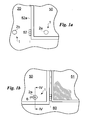
- the device according to the invention is indicated as a whole with the number 1.
- shutter identifies any type of element, extending substantially along a plane, suitable to close or free an opening 51, part of a wall, of a piece of furniture or the like.
- the shutter 50 is preferably movable by means of rotation about one or more pivot pins 52, defining an axis of rotation 52a.
- the shutter 50 can also be positioned against a supporting surface 60, realized in particular by the external wall of the building on which the door or window is placed.
- the shutter 50 can be disposed in a first closed position, in which it is suitable to close the opening 51, shown in Fig. 1a , or in the open position, shown in Figs. 1b , 8a and 8b , in which it is adjacent to the supporting surface 60.
- the locking device 1 is suitable to lock the shutter 50 in an open position, in particular in the position adjacent to the supporting surface 60.
- the locking device 1 comprises a movable coupling element 2a, constrained to the shutter 50, and a fixed coupling element 2b, constrained to the supporting surface 60.
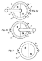
- the coupling elements 2a and 2b respectively comprise at least a first and a second magnet 3a and 3b.
- magnets 3a and 3b are substantially positioned side by side when the shutter 50 is in the open position.
- the device 1 can be disposed in an engaged configuration, in which it is suitable to lock the shutter 50 in the open position, and in a disengaged position, in which it allows and preferably facilitates closing of the shutter 50.
- Variation of the configuration of the device 1 takes place through specific handling means 4 suitable to vary the reciprocal position of the magnets 3a and 3b and consequently of the coupling elements 2a and 2b between said engaged and disengaged configurations or positions.
- the engaged and disengaged configurations are such that, when the shutter 50 is in the open position, the magnets 3a and 3b in the engaged position reciprocally attract each other, while the magnets 3a and 3b in the disengaged configuration reciprocally repel each other.
- the magnets 3a and 3b are realized by permanent magnets made of ferromagnetic material.
- permanent magnets comprise a north pole N and a south pole S and opposite poles attract each other, while identical poles repel each other. They are thus selectively positionable in a position of reciprocal attraction or repulsion.
- the magnets 3a and 3b each comprise a North pole N and a South pole S both facing the contact surface 3c, or alternatively one of the two magnets 3a or 3b, and in particular the fixed magnet 3a, can utilize a single pole, for the objects described below.
- poles of opposite polarity of the first and second magnets 3a and 3b are facing, while in the disengaged configuration of the device 1 poles of the same polarity of the first and second magnet 3a and 3b are facing.
- the force of reciprocal attraction of the magnets 3a and 3b is thus suitable to reciprocally engage the movable coupling element 2a and the fixed coupling element 2b, and consequently the shutter 50 with the supporting surface 60.
- the force of reciprocal attraction of the magnets 3a and 3b can be the direct cause of this engagement, as shown in Figs. 1 a to 5 and as indicated in example 1 below.
- FIG. 1a to 5 A first example of embodiment of the device 1 is shown in Figs. 1a to 5 .
- each magnet 3a or 3b comprises two poles, a pole N and a pole S.
- the North pole N of the first magnet 3a is facing the South pole S of the second magnet 3b and, vice versa, the South pole S of the first magnet 3a is facing the North pole N of the second magnet 3b.
- the North pole N of the first magnet 3a is facing the North pole N of the second magnet 3b and, vice versa, the South pole S of the first magnet 3a is facing the South pole S of the second magnet 3b.
- first magnets 3a there can also be a plurality of magnets 3a disposed on the movable coupling element 2a and a plurality of second magnets 3b disposed on the fixed coupling element 2b.
- the number of first magnets 3a is the same as the number of second magnets 3b.
- magnets 3a and 3b are preferably all facing each other according to opposite polarities in the engaged position and according to the same polarities in the disengaged position, as described above.
- the magnets 3a and 3b are also preferably circular and realized by magnetic disks having two semi-circles, divided diametrically, of opposite polarities, as shown in Figs. 2a, 2b and 3 .
- These preferably have a thickness of approximately 2.5 cm and a diameter of 2.5 cm and are suitable to magnetically support maximum loads of about 20 kg in weight.
- magnets 3a and 3b there are a plurality of magnets 3a and 3b, the overall shape of which is circular and divided radially into a plurality of poles N and S, for example in 4, 6 or more poles.
- the magnets 3a and 3b have a rectangular plan and are divided into two or more poles in a longitudinal or vertical direction.
- the reciprocal position of the magnets 3a and 3b is varied by the handling means 4 that dispose these magnets 3a and 3b in the engaged or disengaged configuration.
- These handling means 4 are preferably disposed on only one of the coupling elements 2a and 2b, and in particular on the movable coupling element 2a.
- a rotational hinge 5 suitable to allow rotation of the magnets 3a in the direction 5a, perpendicular to the contact surface 3a.
- the handling means 4 also comprise a control lever 6, suitable to manually operate rotation of the magnets 3a.
- the lever 6 is placed on the face of the shutter 50 opposite the face closest to the contact surface 3c.
- These handling means 4 are suitable to allow rotation of the magnets 3a by an angle of approximately 180° in the case in which the magnets are circular and divided into two portions, otherwise in the case in which the magnets are in turn composed of several magnets, rotations of smaller angles are sufficient.
- handling means 4 comprising linear hinges or the like can be disposed.
- Fig. 4 shows handling means 4 comprising a hinge 5 realized by a first cylindrical bushing 5b, containing the first magnet 3a, rotatable about a second cylindrical bushing 5c, fixed to the shutter 50 by means of bearings 5d.
- Fig. 5 shows handling means 4 comprising a different lever 6 with respect to the lever shown in Figs. 2a and 2b .
- This lever 6 in fact comprises a plurality of rods 6a and hinges 6b suitable to actuate the rotation movement of the hinge 5.
- This lever 6 has both ends fastened to the shutter 50 and is also positioned in proximity to the axis of rotation 52a to allow fast and easy use.
- the handling means 4 finally comprise an elastic return element 8a, suitable to maintain the device 1 in the engaged position, and a limit stop element 8b. These are preferably realized by a circular spring and a limit stop pin respectively.
- the coupling elements 2a and 2b which contain the magnets 3a and 3b, comprise covering surfaces of these magnets 3a and 3b, suitable to prevent direct reciprocal contact of the magnets 3a and 3b.
- the coupling elements 2a and 2b also comprise constraining means 9, relative respectively to the shutter 50 and to the supporting surface 60.
- constraining means 9 are preferably constituted by flanges and expansion screws or plugs, while said covering surfaces 8 are preferably made of brass, or of polymer material, to give the coupling elements 2a and 2b an appealing external appearance.
- the movable coupling element 2a is preferably positioned on the shutter 50 at a distance of between 10 cm and 30 cm from the axis of rotation 52a thereof and on the lower side of the shutter 50 to allow the lever 6 to be grasped comfortably.
- the fixed coupling element 2b can be placed aligned with the supporting surface 60 or separated therefrom.
- the fixed coupling element 2b is placed at a suitable distance from the supporting surface 60, for example to prevent the handle on the side facing the surface 60 of the shutter 50 from coming into contact with said surface 60.
- this distance of the fixed coupling element 2b from the surface 60 can be adjustable.
- FIG. 6a to 8c A second example of embodiment of the device 1 is shown in Figs. 6a to 8c .
- the fixed coupling element 2b comprises a locking element 7, suitable to constrain the shutter 50.
- the first magnet 3a comprises a North pole N and a South pole S that can be selectively placed adjacent to a pole of a polarity, i.e. South, of the second magnet 3b.
- the North pole N of the first magnet 3a is facing the South pole S of the second magnet 3b
- the South pole S of the first magnet 3a is facing the South pole S of the second magnet 3b
- magnets 3a and 3b are preferably all facing each other according to opposite polarities in the engaged position and according to the same polarities in the disengaged position, as described above.
- the first magnets 3a preferably have a rectangular median section, in the plane parallel to the principal plane of extension of the shutter 50, as shown in Figs. 6a and 6b . They are also divided into two or more poles in a longitudinal direction 1a.
- the second magnets 3b can be realized of any shape and type. In particular, it is sufficient for a single polarity of the second magnets 3b to be facing the first magnets 3a, as shown in Figs. 6a-7b .
- the second magnets also to comprise a plurality of poles N and S facing the first magnets and also divided in a longitudinal direction 1a.
- At least one of the magnets 3a and 3b is movable inside the coupling elements 2a and 3a.
- first magnets 3a are movable in a substantially longitudinal direction 1a with respect to the first coupling element 2a.
- the movable coupling element 2a then comprises an external body 2c suitable to contain the first magnets 3a and to allow sliding thereof in a substantially longitudinal direction 1a.
- This external body 2c is preferably substantially parallelepiped in shape and made of metal, preferably brass, or alternatively of polymer material.
- the fixed coupling element 2b comprises second magnets 3b which preferably maintain their fixed position with respect to this coupling element 2b.
- This fixed coupling element 2b can preferably be disposed in two different engaged ( Figs. 6a and 7a ) and disengaged ( Figs. 6b and 7b ) positions, in said engaged and disengaged configurations of the device 1.
- the movable coupling element 2a is rotatable in a direction parallel to the longitudinal direction 1a about a pin 2d, integral with the supporting surface 60 ( Figs. 3 and 4 ) and is disposed with two different angles in said engaged and disengaged positions.
- the locking element 7 preferably realized by a plate or the like, suitable to prevent movement of the shutter 50 about the pivot pins 52, when the fixed coupling element 2b is disposed in the engaged position, and to allow movement of the shutter 50 about the pivot pins 52, when the fixed coupling element 2b is disposed in the disengaged position.
- the reciprocal position of the magnets 3a and 3b is varied by the handling means 4 that dispose these magnets 3a and 3b in the engaged or disengaged position.
- These handling means 4 are preferably disposed on only one of the coupling elements 2a and 2b, and in particular on the first coupling element 2a.
- the handling means 4 are preferably suitable also to perform closing of the shutter 50.
- the handling means 4 are realized by a system 4a of rods and hinges.
- the system 4a comprises a first and a second rod 10a and 10b reciprocally constrained by a first rotational hinge 11a.
- the first rod 5a is placed in proximity to the pivot pins 52 of the shutter 50, is constrained to this shutter 50 by means of a second rotational hinge 11 b and comprises a handle 11c, suitable to allow manual rotation of this first rod 5a about the second rotational hinge 6b.
- the second rod 10b is instead constrained to the movable coupling element 2a.
- this rod 10b comprises the first magnets 3a and is inserted inside the external body 2c, part of the movable coupling element 2a.
- the external body 2c is suitable to allow sliding in a substantially longitudinal direction 1a of the first magnets 2a.
- the direction is substantially longitudinal 1 a because the second rod 10b performs a slight rotation with respect to the longitudinal direction 1a, as shown in Fig. 6b . Therefore, the external body 2c does not constrain the second rod 10b tightly, but allows it to rotate by a few degrees in a direction perpendicular to the longitudinal direction 1a.
- an elastic element 12 suitable to maintain the first magnets in the engaged position ( Fig. 6a ).
- the handling means 4 are realized by a cord 4b, chain or the like.
- the first magnets 3a are constrained to a rod 10 suitable to slide in a substantially longitudinal direction 1a inside the constraining body 1c in opposition to the elastic element 8.
- this cord 4b it is also preferable for this cord 4b to join two different coupling elements 2a of two different shutters 50 placed in a same opening 51, as shown in Figs. 8a, 8b and 8c .
- FIGs. 9a to 10b A further example of embodiment of the device 1 is shown in Figs. 9a to 10b . It is very similar to the device 1 in example 2.
- the fixed coupling element 2b comprises a locking element 7, suitable to constrain the shutter 50 and also the handling means 4 are substantially identical and comprise a system 4a of rods and hinges or a cord or chain 4b, as shown in Figs. 8a-8c .
- the handling means 4 are suitable to allow rotation at least of the first magnets 3a and in particular of a portion of the movable coupling element 2a including the first magnets 3a, as shown in Figs. 9a and 9b .
- the handling means comprise a rotational hinge 13 suitable to allow rotation of the magnets 3a in a direction perpendicular to the contact surface.
- the movable coupling element 3a comprises, in proximity to the fixed coupling element 3b and in particular to the locking element 7, a surface with a shape suitable to move the fixed coupling element 3b away when the device 1 is in the released position, as shown in Fig. 9b .
- the fixed coupling element 3b of the present example is similar to the fixed coupling element 3b of the previous example. However, it can include some variants.
- a supporting body 14 realized by a body disposed in the lower portion of the fixed coupling element 3b and shown in Figs. 10 and 10b .
- the fixed coupling element 3b comprises a second magnet 2b positioned directly in the locking element 7.
- the shutter 50 is in the closed position ( Fig. 1a ) and closes the opening 51.
- the device 1 is in the engaged configuration ( Figs. 2a , 6a , 9a , 10a ) and the magnets 3a and 3b are reciprocally attracted.
- the magnets 2a and 2b maintain the shutter 50 in the open position by means of the force of magnetic attraction or by means of maintaining the fixed coupling element in the engaged position.
- the force of reciprocal attraction, or the locking element 7 maintains the shutter 50 in the open position also in the case of wind or other atmospheric events and the like.
- the device 1 is thus positioned in the disengaged configuration.
- activation of the supporting means 14 by means of the described control lever 6, handle 11c or cord 4b, facilitates closing of the shutter 50.
- the shutter 50 is released and pushed rapidly toward the closed position.
- the invention achieves important advantages.
- the device 1 is capable of allowing easy disengagement and closing of the shutter 50 or, vice versa, easy opening and engagement of said shutter 50.
- the rotational movement required to disengage and close the shutter is very fast and easy, as is the opening and engaging movement, which involves a simple push of the shutter 50.
- the device 1 then comprises comfortable use of the handling means 4 described, in particular if performed according to the descriptions indicated.
- Last but not least advantage is realized by the fact that the device 1 is aesthetically pleasing and that is can be applied substantially to all types of shutters.
- the invention is susceptible to modifications and variants falling within the inventive concept.
- the handling means 4 can be automatic, electric or the like, instead of manual.
Landscapes
- Physics & Mathematics (AREA)
- Electromagnetism (AREA)
- Engineering & Computer Science (AREA)
- Mechanical Engineering (AREA)
- Operating, Guiding And Securing Of Roll- Type Closing Members (AREA)
Applications Claiming Priority (2)
| Application Number | Priority Date | Filing Date | Title |
|---|---|---|---|
| ITMI20070112 ITMI20070112A1 (it) | 2007-01-26 | 2007-01-26 | Dispositivo di blocco per battenti di serramenti e simili |
| ITMI20071323 ITMI20071323A1 (it) | 2007-07-04 | 2007-07-04 | Dispositivo di bloccaggio per battenti di serramenti e simili |
Publications (1)
| Publication Number | Publication Date |
|---|---|
| EP1950370A1 true EP1950370A1 (fr) | 2008-07-30 |
Family
ID=39433780
Family Applications (1)
| Application Number | Title | Priority Date | Filing Date |
|---|---|---|---|
| EP08001155A Withdrawn EP1950370A1 (fr) | 2007-01-26 | 2008-01-23 | Dispositif de verrouillage pour portes, volets et similaires |
Country Status (1)
| Country | Link |
|---|---|
| EP (1) | EP1950370A1 (fr) |
Cited By (6)
| Publication number | Priority date | Publication date | Assignee | Title |
|---|---|---|---|---|
| WO2010135726A3 (fr) * | 2009-05-22 | 2011-03-03 | Proteqt Technologies, Inc. | Système de verrouillage activé à distance et procédé |
| WO2011088496A1 (fr) * | 2010-01-22 | 2011-07-28 | Stuart John Andrews | Ensemble de verrouillage |
| US20160356057A1 (en) * | 2015-06-03 | 2016-12-08 | HTI Technology & Industries, Inc. | Powered latching apparatus |
| JP2017066815A (ja) * | 2015-10-01 | 2017-04-06 | 堀ロック工業株式会社 | 扉開閉用ハンドル |
| EP2959800B1 (fr) * | 2014-06-27 | 2017-08-30 | Grass GmbH | Meuble avec un dispositif destiné à l'accouplement amovible d'un chargeur intérieur sur un chargeur extérieur d'un meuble |
| US20210115713A1 (en) * | 2018-05-04 | 2021-04-22 | Hgt Innovations Pty Ltd. | Security device |
Citations (8)
| Publication number | Priority date | Publication date | Assignee | Title |
|---|---|---|---|---|
| FR329464A (fr) * | 1903-02-17 | 1903-08-01 | Richard Dolge | Fermeture automatique par aimant |
| FR1179194A (fr) * | 1956-07-21 | 1959-05-21 | Philips Nv | Serrure magnétique |
| FR1201673A (fr) * | 1958-07-09 | 1960-01-04 | Perfectionnements aux fermetures magnétiques, notamment pour portes | |
| DE1553544A1 (de) * | 1966-01-19 | 1969-07-24 | Max Baermann | Schloss mit magnetisch beeinflussbarem Verschlussorgan |
| DE2455520A1 (de) * | 1974-11-23 | 1976-05-26 | Gordon Cockburn | Verschlussvorrichtung, bestehend aus dauermagnet und einem magnetischen gegenpol |
| FR2667647A1 (fr) * | 1990-10-08 | 1992-04-10 | Midi Moulages Plast | Systeme manóoeuvrable d'arret d'un battant de volet et ensemble de crochetage dudit battant. |
| DE29622577U1 (de) * | 1996-12-31 | 1997-04-30 | Schneider Roman | Puffer mit aktivierbarer Feststelleinrichtung |
| US6588811B1 (en) * | 2002-12-03 | 2003-07-08 | Edward B. Ferguson | Reversible magnetic door stop/latch |
-
2008
- 2008-01-23 EP EP08001155A patent/EP1950370A1/fr not_active Withdrawn
Patent Citations (8)
| Publication number | Priority date | Publication date | Assignee | Title |
|---|---|---|---|---|
| FR329464A (fr) * | 1903-02-17 | 1903-08-01 | Richard Dolge | Fermeture automatique par aimant |
| FR1179194A (fr) * | 1956-07-21 | 1959-05-21 | Philips Nv | Serrure magnétique |
| FR1201673A (fr) * | 1958-07-09 | 1960-01-04 | Perfectionnements aux fermetures magnétiques, notamment pour portes | |
| DE1553544A1 (de) * | 1966-01-19 | 1969-07-24 | Max Baermann | Schloss mit magnetisch beeinflussbarem Verschlussorgan |
| DE2455520A1 (de) * | 1974-11-23 | 1976-05-26 | Gordon Cockburn | Verschlussvorrichtung, bestehend aus dauermagnet und einem magnetischen gegenpol |
| FR2667647A1 (fr) * | 1990-10-08 | 1992-04-10 | Midi Moulages Plast | Systeme manóoeuvrable d'arret d'un battant de volet et ensemble de crochetage dudit battant. |
| DE29622577U1 (de) * | 1996-12-31 | 1997-04-30 | Schneider Roman | Puffer mit aktivierbarer Feststelleinrichtung |
| US6588811B1 (en) * | 2002-12-03 | 2003-07-08 | Edward B. Ferguson | Reversible magnetic door stop/latch |
Cited By (10)
| Publication number | Priority date | Publication date | Assignee | Title |
|---|---|---|---|---|
| WO2010135726A3 (fr) * | 2009-05-22 | 2011-03-03 | Proteqt Technologies, Inc. | Système de verrouillage activé à distance et procédé |
| CN102459789A (zh) * | 2009-05-22 | 2012-05-16 | 保护技术公司 | 遥控启动锁系统以及方法 |
| CN102459789B (zh) * | 2009-05-22 | 2015-09-09 | 保护技术公司 | 遥控启动锁系统以及方法 |
| WO2011088496A1 (fr) * | 2010-01-22 | 2011-07-28 | Stuart John Andrews | Ensemble de verrouillage |
| EP2959800B1 (fr) * | 2014-06-27 | 2017-08-30 | Grass GmbH | Meuble avec un dispositif destiné à l'accouplement amovible d'un chargeur intérieur sur un chargeur extérieur d'un meuble |
| US20160356057A1 (en) * | 2015-06-03 | 2016-12-08 | HTI Technology & Industries, Inc. | Powered latching apparatus |
| US11060322B2 (en) * | 2015-06-03 | 2021-07-13 | Hti Technology And Industries, Inc. | Powered latching apparatus |
| JP2017066815A (ja) * | 2015-10-01 | 2017-04-06 | 堀ロック工業株式会社 | 扉開閉用ハンドル |
| US20210115713A1 (en) * | 2018-05-04 | 2021-04-22 | Hgt Innovations Pty Ltd. | Security device |
| US11795743B2 (en) * | 2018-05-04 | 2023-10-24 | Fantom Hardware Pty Ltd | Security device |
Similar Documents
| Publication | Publication Date | Title |
|---|---|---|
| US7942458B2 (en) | Magnetic gate latch | |
| EP1950370A1 (fr) | Dispositif de verrouillage pour portes, volets et similaires | |
| US7637543B2 (en) | Reversible magnetic door stop/latch | |
| US6000735A (en) | Automatic child-resistant sliding door lock | |
| US8540292B2 (en) | Reversible magnetic door stop/latch | |
| JP5175725B2 (ja) | 窓固定の手段と方法 | |
| US20090115204A1 (en) | Self latching latch | |
| US9470032B2 (en) | Door stop device and method | |
| KR100934781B1 (ko) | 푸쉬 풀 타입의 도어록 장치 | |
| US11060322B2 (en) | Powered latching apparatus | |
| US20170335604A1 (en) | Magnetic lock | |
| KR20160052486A (ko) | 미닫이 창호용 잠금장치 | |
| AU2005221078A1 (en) | Magnetism to control friction checks for rods | |
| US20090109575A1 (en) | Magnetic latch assembly | |
| US11466474B2 (en) | Magnetic lock | |
| US9299270B2 (en) | Door vacancy indicator | |
| US20140191515A1 (en) | Magnetic-pin catch for cabinet or interior room door | |
| JP6831952B2 (ja) | 建具用錠 | |
| JP6228815B2 (ja) | 戸当り | |
| KR101030373B1 (ko) | 자석손잡이를 이용한 자동식 도어 잠금장치 | |
| TW201802341A (zh) | 磁斥式鉸鏈器 | |
| JP2004332519A (ja) | 扉用平面ハンドル装置 | |
| KR20170000540U (ko) | 사물함도어의 손잡이구조 | |
| JP6897972B2 (ja) | 引き戸錠 | |
| CN210480114U (zh) | 洁净室传递窗 |
Legal Events
| Date | Code | Title | Description |
|---|---|---|---|
| PUAI | Public reference made under article 153(3) epc to a published international application that has entered the european phase |
Free format text: ORIGINAL CODE: 0009012 |
|
| AK | Designated contracting states |
Kind code of ref document: A1 Designated state(s): AT BE BG CH CY CZ DE DK EE ES FI FR GB GR HR HU IE IS IT LI LT LU LV MC MT NL NO PL PT RO SE SI SK TR |
|
| AX | Request for extension of the european patent |
Extension state: AL BA MK RS |
|
| 17P | Request for examination filed |
Effective date: 20081021 |
|
| 17Q | First examination report despatched |
Effective date: 20090226 |
|
| AKX | Designation fees paid |
Designated state(s): AT BE BG CH CY CZ DE DK EE ES FI FR GB GR HR HU IE IS IT LI LT LU LV MC MT NL NO PL PT RO SE SI SK TR |
|
| GRAP | Despatch of communication of intention to grant a patent |
Free format text: ORIGINAL CODE: EPIDOSNIGR1 |
|
| STAA | Information on the status of an ep patent application or granted ep patent |
Free format text: STATUS: THE APPLICATION IS DEEMED TO BE WITHDRAWN |
|
| 18D | Application deemed to be withdrawn |
Effective date: 20110719 |