EP1950125A1 - Method and device for mounting soft member - Google Patents
Method and device for mounting soft member Download PDFInfo
- Publication number
- EP1950125A1 EP1950125A1 EP05809325A EP05809325A EP1950125A1 EP 1950125 A1 EP1950125 A1 EP 1950125A1 EP 05809325 A EP05809325 A EP 05809325A EP 05809325 A EP05809325 A EP 05809325A EP 1950125 A1 EP1950125 A1 EP 1950125A1
- Authority
- EP
- European Patent Office
- Prior art keywords
- roller
- speed
- soft member
- weatherstrip
- movement
- Prior art date
- Legal status (The legal status is an assumption and is not a legal conclusion. Google has not performed a legal analysis and makes no representation as to the accuracy of the status listed.)
- Granted
Links
Images


Classifications
-
- B—PERFORMING OPERATIONS; TRANSPORTING
- B60—VEHICLES IN GENERAL
- B60R—VEHICLES, VEHICLE FITTINGS, OR VEHICLE PARTS, NOT OTHERWISE PROVIDED FOR
- B60R13/00—Elements for body-finishing, identifying, or decorating; Arrangements or adaptations for advertising purposes
- B60R13/06—Sealing strips
-
- B—PERFORMING OPERATIONS; TRANSPORTING
- B23—MACHINE TOOLS; METAL-WORKING NOT OTHERWISE PROVIDED FOR
- B23P—METAL-WORKING NOT OTHERWISE PROVIDED FOR; COMBINED OPERATIONS; UNIVERSAL MACHINE TOOLS
- B23P19/00—Machines for simply fitting together or separating metal parts or objects, or metal and non-metal parts, whether or not involving some deformation; Tools or devices therefor so far as not provided for in other classes
- B23P19/04—Machines for simply fitting together or separating metal parts or objects, or metal and non-metal parts, whether or not involving some deformation; Tools or devices therefor so far as not provided for in other classes for assembling or disassembling parts
- B23P19/047—Machines for simply fitting together or separating metal parts or objects, or metal and non-metal parts, whether or not involving some deformation; Tools or devices therefor so far as not provided for in other classes for assembling or disassembling parts for flexible profiles, e.g. sealing or decorating strips in grooves or on other profiles by devices moving along the flexible profile
-
- B—PERFORMING OPERATIONS; TRANSPORTING
- B60—VEHICLES IN GENERAL
- B60J—WINDOWS, WINDSCREENS, NON-FIXED ROOFS, DOORS, OR SIMILAR DEVICES FOR VEHICLES; REMOVABLE EXTERNAL PROTECTIVE COVERINGS SPECIALLY ADAPTED FOR VEHICLES
- B60J10/00—Sealing arrangements
- B60J10/45—Assembling sealing arrangements with vehicle parts
-
- Y—GENERAL TAGGING OF NEW TECHNOLOGICAL DEVELOPMENTS; GENERAL TAGGING OF CROSS-SECTIONAL TECHNOLOGIES SPANNING OVER SEVERAL SECTIONS OF THE IPC; TECHNICAL SUBJECTS COVERED BY FORMER USPC CROSS-REFERENCE ART COLLECTIONS [XRACs] AND DIGESTS
- Y10—TECHNICAL SUBJECTS COVERED BY FORMER USPC
- Y10T—TECHNICAL SUBJECTS COVERED BY FORMER US CLASSIFICATION
- Y10T29/00—Metal working
- Y10T29/49—Method of mechanical manufacture
- Y10T29/49826—Assembling or joining
-
- Y—GENERAL TAGGING OF NEW TECHNOLOGICAL DEVELOPMENTS; GENERAL TAGGING OF CROSS-SECTIONAL TECHNOLOGIES SPANNING OVER SEVERAL SECTIONS OF THE IPC; TECHNICAL SUBJECTS COVERED BY FORMER USPC CROSS-REFERENCE ART COLLECTIONS [XRACs] AND DIGESTS
- Y10—TECHNICAL SUBJECTS COVERED BY FORMER USPC
- Y10T—TECHNICAL SUBJECTS COVERED BY FORMER US CLASSIFICATION
- Y10T29/00—Metal working
- Y10T29/49—Method of mechanical manufacture
- Y10T29/49826—Assembling or joining
- Y10T29/4984—Retaining clearance for motion between assembled parts
- Y10T29/49842—Between tube-forming helical coils
-
- Y—GENERAL TAGGING OF NEW TECHNOLOGICAL DEVELOPMENTS; GENERAL TAGGING OF CROSS-SECTIONAL TECHNOLOGIES SPANNING OVER SEVERAL SECTIONS OF THE IPC; TECHNICAL SUBJECTS COVERED BY FORMER USPC CROSS-REFERENCE ART COLLECTIONS [XRACs] AND DIGESTS
- Y10—TECHNICAL SUBJECTS COVERED BY FORMER USPC
- Y10T—TECHNICAL SUBJECTS COVERED BY FORMER US CLASSIFICATION
- Y10T29/00—Metal working
- Y10T29/49—Method of mechanical manufacture
- Y10T29/49826—Assembling or joining
- Y10T29/4984—Retaining clearance for motion between assembled parts
- Y10T29/49845—Retaining clearance for motion between assembled parts by deforming interlock
-
- Y—GENERAL TAGGING OF NEW TECHNOLOGICAL DEVELOPMENTS; GENERAL TAGGING OF CROSS-SECTIONAL TECHNOLOGIES SPANNING OVER SEVERAL SECTIONS OF THE IPC; TECHNICAL SUBJECTS COVERED BY FORMER USPC CROSS-REFERENCE ART COLLECTIONS [XRACs] AND DIGESTS
- Y10—TECHNICAL SUBJECTS COVERED BY FORMER USPC
- Y10T—TECHNICAL SUBJECTS COVERED BY FORMER US CLASSIFICATION
- Y10T29/00—Metal working
- Y10T29/49—Method of mechanical manufacture
- Y10T29/49826—Assembling or joining
- Y10T29/49863—Assembling or joining with prestressing of part
- Y10T29/4987—Elastic joining of parts
- Y10T29/49872—Confining elastic part in socket
-
- Y—GENERAL TAGGING OF NEW TECHNOLOGICAL DEVELOPMENTS; GENERAL TAGGING OF CROSS-SECTIONAL TECHNOLOGIES SPANNING OVER SEVERAL SECTIONS OF THE IPC; TECHNICAL SUBJECTS COVERED BY FORMER USPC CROSS-REFERENCE ART COLLECTIONS [XRACs] AND DIGESTS
- Y10—TECHNICAL SUBJECTS COVERED BY FORMER USPC
- Y10T—TECHNICAL SUBJECTS COVERED BY FORMER US CLASSIFICATION
- Y10T29/00—Metal working
- Y10T29/53—Means to assemble or disassemble
-
- Y—GENERAL TAGGING OF NEW TECHNOLOGICAL DEVELOPMENTS; GENERAL TAGGING OF CROSS-SECTIONAL TECHNOLOGIES SPANNING OVER SEVERAL SECTIONS OF THE IPC; TECHNICAL SUBJECTS COVERED BY FORMER USPC CROSS-REFERENCE ART COLLECTIONS [XRACs] AND DIGESTS
- Y10—TECHNICAL SUBJECTS COVERED BY FORMER USPC
- Y10T—TECHNICAL SUBJECTS COVERED BY FORMER US CLASSIFICATION
- Y10T29/00—Metal working
- Y10T29/53—Means to assemble or disassemble
- Y10T29/53657—Means to assemble or disassemble to apply or remove a resilient article [e.g., tube, sleeve, etc.]
-
- Y—GENERAL TAGGING OF NEW TECHNOLOGICAL DEVELOPMENTS; GENERAL TAGGING OF CROSS-SECTIONAL TECHNOLOGIES SPANNING OVER SEVERAL SECTIONS OF THE IPC; TECHNICAL SUBJECTS COVERED BY FORMER USPC CROSS-REFERENCE ART COLLECTIONS [XRACs] AND DIGESTS
- Y10—TECHNICAL SUBJECTS COVERED BY FORMER USPC
- Y10T—TECHNICAL SUBJECTS COVERED BY FORMER US CLASSIFICATION
- Y10T29/00—Metal working
- Y10T29/53—Means to assemble or disassemble
- Y10T29/53709—Overedge assembling means
-
- Y—GENERAL TAGGING OF NEW TECHNOLOGICAL DEVELOPMENTS; GENERAL TAGGING OF CROSS-SECTIONAL TECHNOLOGIES SPANNING OVER SEVERAL SECTIONS OF THE IPC; TECHNICAL SUBJECTS COVERED BY FORMER USPC CROSS-REFERENCE ART COLLECTIONS [XRACs] AND DIGESTS
- Y10—TECHNICAL SUBJECTS COVERED BY FORMER USPC
- Y10T—TECHNICAL SUBJECTS COVERED BY FORMER US CLASSIFICATION
- Y10T29/00—Metal working
- Y10T29/53—Means to assemble or disassemble
- Y10T29/53709—Overedge assembling means
- Y10T29/53717—Annular work
- Y10T29/53726—Annular work with second workpiece inside annular work one workpiece moved to shape the other
- Y10T29/5373—Annular work with second workpiece inside annular work one workpiece moved to shape the other comprising driver for snap-off-mandrel fastener; e.g., Pop [TM] riveter
- Y10T29/53752—Annular work with second workpiece inside annular work one workpiece moved to shape the other comprising driver for snap-off-mandrel fastener; e.g., Pop [TM] riveter having rotary drive mechanism
-
- Y—GENERAL TAGGING OF NEW TECHNOLOGICAL DEVELOPMENTS; GENERAL TAGGING OF CROSS-SECTIONAL TECHNOLOGIES SPANNING OVER SEVERAL SECTIONS OF THE IPC; TECHNICAL SUBJECTS COVERED BY FORMER USPC CROSS-REFERENCE ART COLLECTIONS [XRACs] AND DIGESTS
- Y10—TECHNICAL SUBJECTS COVERED BY FORMER USPC
- Y10T—TECHNICAL SUBJECTS COVERED BY FORMER US CLASSIFICATION
- Y10T29/00—Metal working
- Y10T29/53—Means to assemble or disassemble
- Y10T29/53709—Overedge assembling means
- Y10T29/53787—Binding or covering
- Y10T29/53791—Edge binding
Definitions
- the present invention relates to an improvement in a method and apparatus for mounting a soft member.
- Soft-member-mounting methods or apparatuses are well known, as disclosed in JP-B-5-65298 showing use of robots to mount a soft member or a weather stripping in a vehicle door opening. With reference to Fig. 10 hereof, discussion will be made as to mounting such a weather stripping in the vehicle door opening.
- a vehicle body 100 includes a flange 102 provided in an opening 101 in which a vehicle door is to be installed.
- An arm tooling device 104 is mounted to a wrist 103 of a robot.
- the arm tooling device 104 includes a pressure roller 106 for pressing a weather stripping 107 against the flange 102 to fit the weather stripping 107 in the flange 102.
- the pressure roller 106 is driven by a motor and has a rotational speed varied by a clutch connecting or disconnecting a drive between the pressure roller 106 and the motor.
- the clutch disconnects the drive between the pressure roller 106 and the motor such that the arm tooling device 104 moves allowing the pressure roller 106 to free wheel on the straight section of the opening 101.
- the clutch connects the drive between the pressure roller 106 and the motor to rotate the pressure roller on the corner at a higher rotational speed than on the straight section such that slacks in the weather stripping 107 are taken up.
- the weather stripping 107 can be pushed in a direction of movement of the pressure roller 106, slackening in front of the pressure roller 106.
- a method for mounting a soft member on an elongated member by fitting the soft member into the elongated member, the elongated member having a substantially U-shaped cross-section, the soft member having an elongated configuration comprising the steps of: temporarily attaching the soft member to the elongated member; and rotating a roller while moving the roller on a route provided along the elongated member with the roller pressing the soft member, such that a pressed surface of the roller pressed against the soft member has a peripheral speed either equal to a speed of the movement of the roller or higher than the speed of the movement, of the roller by a maximum of 10 % of the speed of the movement of the roller when the roller reaches at least one part of the route, wherein a pressing force of the roller exerted on the soft member is always constant as the roller presses the soft member.
- the roller rotates such that the peripheral speed of the pressed surface of the roller is either equal to the speed of the movement of the roller or higher than the speed of the movement of the roller by the maximum of 10 % of the speed of the movement of the roller when the roller reaches at least one part of the route. This rotation of the roller pulls the soft member back in a direction opposite to the direction of the movement of the roller.
- the soft member Since the pressing force of the roller exerted on the soft member is always constant as the roller presses the soft member, the soft member can be entirely and uniformly mounted on the elongated member of substantially U-shaped cross-section. In other words, it becomes possible to prevent the soft member from slackening or stretching in the direction of the movement of the roller when the soft member is fitted in the elongated member.
- the exertion of the constant pressing force of the roller on the soft member enables the soft member to be uniformly fitted in the elongated member, which improves quality of the soft member fitted in the elongated member.
- the soft member of improved quality need not be repaired nor detached from and again mounted to the elongated member, which leads to improved productivity of vehicles.
- an apparatus for mounting a soft member on an elongated member by fitting the soft member into the elongated member, the elongated member having a substantially U-shaped cross-section, the soft member having an elongated configuration comprising: a roller rotated by an actuator; moving means for moving the roller along the elongated member with the roller pressing the soft member against the elongated member, a force sensor disposed between the roller and the moving means for detecting a reaction force applied to the roller; and a control unit for controlling the roller on the basis of the reaction force detected by the force sensor, such that a pressing force of the roller to press the soft member is constant while a pressed surface of the roller pressed against the soft member has a peripheral speed either equal to a speed of the movement of the roller or higher than the speed of the movement of the roller by a maximum of 10 % of the speed of the movement of the roller.
- the force sensor detects the reaction force applied to the roller. Based on this detected reaction force, the control unit drives the moving unit to control the position of the roller relative to the soft member such that the pressing force of the roller exerted on the soft member is constant.
- the control unit controls the roller such that as the roller moves along the elongated member with the constant pressing force of the roller exerted on the soft member, the peripheral speed of the pressed surface of the roller is either equal to the speed of the movement of the roller or higher than the speed of the movement of the roller by the maximum of 10 % of the speed of the movement of the roller.
- the force sensor detects the reaction force applied to the roller pressing the soft member, in order that the control unit keeps the roller pressing force constant. With the constant pressing force exerted on the soft member, the soft member can be uniformly fitted in the elongated member.
- control unit controls the roller such that the peripheral speed of the pressed surface of the roller is either equal to the speed of the roller moved by the moving unit or higher than the speed of the roller by the maximum of 10 % of the speed of the roller.
- This control of the roller prevents the soft member from slackening or stretching in the direction of the movement of the roller when the soft member is fitted in the elongated member.
- the soft member mounted on the elongated member provides improved quality.
- the soft member of improved quality need not be repaired nor detached from and again mounted on the elongated member, which provides improved productivity of vehicles.
- a weatherstrip-mounting apparatus 12 for mounting a weatherstrip (a soft member) 11 on an outer peripheral edge of a vehicle door 10.
- the apparatus 12 is a robot including a base 15 attached to a floor, a rotatable base 16 rotatably mounted on the base 15, a first arm 17 attached to the base 16, a second arm 18 attached to the first arm 17, a roller unit 20 attached to a distal end portion of the second arm 18, and a roller control unit 22.
- the roller unit 20 includes a roller 21.
- the roller control unit 22 controls both a pressing force of the roller 21 exerted on the weatherstrip 11 and a peripheral speed of a pressed surface 21a ( Fig. 3 ) of the roller 21 pressed against the weatherstrip 11 as the roller 21 presses the weatherstrip 11 so as to mount the weatherstrip 11 to the vehicle door 10.
- the rotatable base 16, the first arm 17, the second arm 18 and a pivotal base 28 ( Fig. 3 ) jointly constitute a moving unit 23 for moving the roller 21.
- Fig. 2 shows that the vehicle door 10 includes an inner panel 25 located on a passenger-compartment-side, an outer panel 26 attached to an exterior side of the inner panel 25, and a sash 27 attached to tops of the panels 25, 26.
- the weatherstrip 11 is mounted on outer peripheral edges of the inner panel 11 and the sash 27.
- the roller unit 20 includes a force sensor 32 connected to the pivotal base 28 swingably supported by the second arm 18, a servomotor 33 attached to a distal end of the force sensor 32, and the roller 21 driven by the servomotor 33.
- the pressed surface 21a of the roller 21 defines an outer peripheral surface of the roller 21.
- the roller 21 is attached to a distal end portion of a roller-supporting shaft 36 attached to a rotational shaft of the servomotor 33.
- the force sensor 32 detects a force directed in a direction along each of three axes (an X axis, a Y axis and a Z axis) perpendicular to each other. It is to be noted that the X axis extends in a direction of extension of the rotational shaft of the servomotor 33 or the roller-supporting shaft 36, the Z axis extends vertically, and the Y axis extends perpendicularly to the X axis and the Z axis. The force sensor 32 also detects torque about each of the X axis, the Y axis and the Z axis. The force sensor 32 outputs the detected force as a force signal.
- the servomotor 33 has a speed controlled by the roller control unit 22. More specifically, the speed of the servomotor 33 is controlled such that as the roller 21 moves along the edge of the vehicle door 10, a peripheral speed of the pressed surface 21a of the roller 21 is either equal to a speed of the movement of the roller 21 (the speed of the movement of the roller 21 is generated by the moving unit 23) or higher than the speed of the movement of the roller 12 by a maximum of 10 % of the speed of the movement of the roller 21.
- Fig. 4 shows the weatherstrip 11 mounted on the vehicle door.
- the sash 27 includes a wall portion 41 located on a vehicle outside, an extension portion 42 horizontally extending from the wall portion 41 towards the passenger-compartment-side, a projection portion 43 formed at an end portion of the extension portion 42 and located on the passenger-compartment-side, and a U-shaped cross-sectional portion 44 formed on a top of the extension portion 42.
- the U-shaped cross-sectional portion 44 includes a first projection portion 46, a second projection portion 47, and a bottom portion 48.
- the weatherstrip 11 includes a fitted portion 51 fitted in the U-shaped cross-sectional portion 44 of the sash 27.
- the weatherstrip 11 also includes an outward projecting portion 52, a first recess portion 53 and a first lip portion 54 all of which are located on a side of the fitted portion 51 facing towards the vehicle outside.
- the weatherstrip 11 further includes a second recess portion 56 and a second lip portion 57 that are located on a side of the fitted portion 51 facing towards the passenger-compartment-side.
- the fitted portion 51 has first and second leg portions 61, 62.
- Reference numeral 63 designates a hollow portion 63. Between the first lip portion 54 and the second lip portion 57 is located a recess 64.
- the roller 21 presses the weatherstrip 11 with the pressed surface 21 pressed against the recess 64 of the weatherstrip 11.
- Fig. 5 shows an electrical block diagram of the roller control unit 22.
- the roller control unit 22 includes a setting section 71, a subtracter 72, a force operating section 73, a control section 74, a roller peripheral speed operating section 78 and a subtracter 79.
- the setting section 71 sets a target value F of a pressing force of the roller 21 pressing the weatherstrip 11.
- the force operating section 73 calculates a reaction force R applied to the roller 21 on the basis of a force signal SF output from the force sensor 32.
- the subtracter 72 calculates a difference ⁇ F (R-F) between the reaction force R output from the force operating section 73 and the target value F output from the setting section 71.
- the roller peripheral speed operating section 78 calculates a peripheral speed V2 of the pressed surface 21a of the roller 21 on the basis of a speed signal SV output from a motor speed detecting section 77 provided for detecting a speed of the servomotor 33.
- the subtracter 79 compares the peripheral speed V2 calculated by the section 78 with a speed V1 of movement of the roller 21 along the sash 27 to thereby calculate a difference A V (V2-V1) between the peripheral speed V2 and the speed V1.
- the speed V1 is output from a second driving section 83.
- the control section 74 outputs a motor speed controlling signal SC, a first position controlling signal SP1, and a second position controlling signal SP2 on the basis of the difference ⁇ F output from the subtracter 72 and the difference ⁇ V output from the subtracter 79.
- the weatherstrip 11 is temporarily attached to the sash 27 with the second leg portion 62 engaged with the second projection portion 47 of the U-shaped cross-sectional portion 44 of the sash 27.
- the first leg portion 61 of the weatherstrip 11 is put on the first projection portion 46 of the sash 27.
- the roller 21 is rotated by the servomotor in a direction of an arrow A while moving on a route provided along the sash 27 in a direction of an arrow B. At this time, the roller 21 presses the weatherstrip 11 temporarily attached to the sash 27, thereby mounting the weatherstrip 11 on the sash 27.
- a roller 110 moves at a speed V1 freely rotating without being fed with power from power source.
- the movement of the roller 110 at the speed V1 pushes the weatherstrip 111 in a direction of the movement of the roller 110, as shown by an arrow C.
- a slack part 113 lifted off the sash 112 is formed in the weatherstrip 111 in front of the roller 110.
- the roller 21 rotates in a direction shown by an arrow D such that a peripheral speed of a roller outer peripheral surface, i.e., the pressed surface 21a pressed against the weatherstrip 111 is equal to the speed V1 of the roller 21.
- the rotation of the roller in the manner shown in Fig. 8B causes the weatherstrip 11 to move back in a direction shown by an arrow E.
- the weatherstrip can be uniformly mounted on the sash 27 without slackening in the direction of the movement of the roller 21.
- Fig. 9A and Fig. 9B illustrate the weatherstrip 11 pressed against the sash 27.
- the roller 21 is pressed against the recess 64 of the weatherstrip 11 in a direction perpendicular to the extension portion 42 with a pressing force F exerted on the recess 64.
- a sash 91 identical in structure to the sash 27
- a sash 91 slants through an angle ⁇ relative to the sash 27 of Fig. 9A
- the roller 21 is pressed against the recess 64 in the direction perpendicular to the extension portion 42 such that horizontal and vertical components FH, FV of a pressing force F are exerted on the recess 64.
- the control section 74 outputs the first position controlling signal SP1 to a robot-driving section 81 of the weatherstrip-mounting apparatus 12, more specifically, to a first driving section 82 from which a fist driving signal SD1 is output to the moving unit 23 for driving the moving unit 23 to move the roller unit 20 closely to or away from the sash 27 such that the roller 21 presses the weatherstrip 11 with the pressing force of the target value F exerted on the weatherstrip 11.
- the control section 74 outputs the second position controlling signal SP2 on the basis of which the second driving section 83 outputs a second driving signal SD2. Based on this signal SD2, the moving unit 23 moves the roller 21 along the sash 27 at a predetermined speed V1.
- the second driving section 83 gives the subtracter 79 such a speed V1.
- the control section 74 outputs the motor speed controlling signal SC to a motor driving section 84 from which a motor driving signal SDM is output to the servomotor 33 to control a speed of the servomotor 33.
- the peripheral speed V2 of the roller 21 is always equal to the speed V1 as the roller moves on the route provided along the sash 27.
- the speed V2 becomes higher than the speed V1 (for example, by a maximum of 10 % of the speed V1) at a time the roller 21 reaches at least one part of the route provided along the sash 27, and the speed V1 is equal to the speed V1 as the roller 21 moves on the rest of the route.
- a method for mounting the weatherstrip 11 (an elongated soft member) on the substantially-U-shaped-cross-sectional sash 27 (an elongated member) by fitting the weatherstrip 11 into the sash 27 comprises the steps of: temporarily attaching the weatherstrip 11 to the sash 27; and rotating the roller 21 while moving the roller 21 on the route provided along the sash 27 with the roller 21 pressing the weatherstrip 11, such that the pressed surface 21a of the roller 21 has the peripheral speed V2 ( Fig.
- the weatherstrip-mounting apparatus 12 for mounting the elongated weatherstrip 11 on the substantially-U-shaped-cross-sectional sash 27 by fitting the weatherstrip 11 into the sash 27, as shown in Fig. 1 , Fig. 3 and Fig. 4 .
- the apparatus 12 comprises: the roller 21 rotated by the servomotor (an actuator) 33; moving unit (moving means) 23 for moving the roller 21 along the sash 27 with the roller 21 pressing the weatherstrip 11 against the sash 27; the force sensor 32 disposed between the roller 21 and the moving unit 23 for detecting a reaction force R applied to the roller 21; and the control unit 22 for controlling the roller 21 on the basis of the reaction force R detected by the force sensor 32, such that a pressing force of the roller 21 to press the weatherstrip 11 is constant while the pressed surface 21a of the roller 21 has a peripheral speed either equal to a speed of the movement of the roller 21 or higher than the speed of the movement of the roller 21 by a maximum of 10 % of the speed of the movement of the roller 21.
- the roller 21 presses the weatherstrip 11 while rotating such that the peripheral speed V2 of the pressed surface 21a of the roller 21 is equal to the speed V1 or higher than the speed V1 by a maximum of 10 % of the speed V1 when the roller reaches at least one part of the route.
- This rotation of the roller 21 prevents the weatherstrip 11 from slackening or stretching in the direction of movement of the roller 21 when the weatherstrip 11 is fitted in the sash 27.
- the force sensor 32 detects the reaction force applied to the roller 21, such that the roller 21 presses the weatherstrip 11 with the constant pressing force to thereby fit the weatherstrip 11 uniformly in the sash 27.
- the weatherstrip 11 thus fitted in the sash 27 has a high quality, and need not repaired nor detached from and again mounted to the sash 27, which improves productivity of the vehicles.
- the roller 21 rotates such that the peripheral speed V2 of the pressed surface 21a of the roller 21 is equal to the speed V1 of the movement of the roller 21 along the sash 27 or higher than the speed V1 by the maximum of 10 % of the speed V1.
- the force sensor 32 detects a force acting on the roller 21 in a direction along the sash 27 or a torque acting about the rotational shaft of the roller 21, and the peripheral speed V2 of the roller 21 is controlled on the basis of the detected force or torque to prevent slackening of the weatherstrip 11.
- the peripheral speed V2 after becoming higher than the speed V1 by the maximum of 10 % of the speed V1, may decrease to a speed equal to the speed V1 if necessary.
- the method and apparatus for mounting a soft member is suitable for mounting a weatherstrip on a vehicle door.
Landscapes
- Engineering & Computer Science (AREA)
- Mechanical Engineering (AREA)
- Automobile Manufacture Line, Endless Track Vehicle, Trailer (AREA)
- Automatic Assembly (AREA)
- Tyre Moulding (AREA)
Abstract
Description
- The present invention relates to an improvement in a method and apparatus for mounting a soft member.
- Soft-member-mounting methods or apparatuses are well known, as disclosed in
JP-B-5-65298 Fig. 10 hereof, discussion will be made as to mounting such a weather stripping in the vehicle door opening. - As shown in
Fig. 10 , avehicle body 100 includes aflange 102 provided in an opening 101 in which a vehicle door is to be installed. Anarm tooling device 104 is mounted to awrist 103 of a robot. Thearm tooling device 104 includes apressure roller 106 for pressing a weather stripping 107 against theflange 102 to fit the weather stripping 107 in theflange 102. Thepressure roller 106 is driven by a motor and has a rotational speed varied by a clutch connecting or disconnecting a drive between thepressure roller 106 and the motor. - Where the
pressure roller 106 mounts the weather stripping 107 to a straight section of the door opening 101, the clutch disconnects the drive between thepressure roller 106 and the motor such that thearm tooling device 104 moves allowing thepressure roller 106 to free wheel on the straight section of theopening 101. Where theweather stripping 107 is mounted to a corner of the door opening 101, the clutch connects the drive between thepressure roller 106 and the motor to rotate the pressure roller on the corner at a higher rotational speed than on the straight section such that slacks in theweather stripping 107 are taken up. - As the
pressure roller 106 free wheels on the straight section of the door opening 101, theweather stripping 107 can be pushed in a direction of movement of thepressure roller 106, slackening in front of thepressure roller 106. - Large slacks in the
weather stripping 107 can not be taken up even if the rotational speed of thepressure roller 106 is made high when the roller arrives at the corner of the door opening 101. As a result, the weather stripping 107 can wrinkle or be lifted up. The wrinkled or lifted weather stripping 107 mounted to the door opening 101 is poor in quality and thus should be repaired or detached from and again mounted to the door opening 101, which leads to decrease in productivity of vehicles. - There is a need to enhance quality of the soft member mounted to the vehicle door openings for improving productivity of vehicles.
- According to a first aspect of the invention, there is provided a method for mounting a soft member on an elongated member by fitting the soft member into the elongated member, the elongated member having a substantially U-shaped cross-section, the soft member having an elongated configuration, the method comprising the steps of: temporarily attaching the soft member to the elongated member; and rotating a roller while moving the roller on a route provided along the elongated member with the roller pressing the soft member, such that a pressed surface of the roller pressed against the soft member has a peripheral speed either equal to a speed of the movement of the roller or higher than the speed of the movement, of the roller by a maximum of 10 % of the speed of the movement of the roller when the roller reaches at least one part of the route, wherein a pressing force of the roller exerted on the soft member is always constant as the roller presses the soft member.
- The roller rotates such that the peripheral speed of the pressed surface of the roller is either equal to the speed of the movement of the roller or higher than the speed of the movement of the roller by the maximum of 10 % of the speed of the movement of the roller when the roller reaches at least one part of the route. This rotation of the roller pulls the soft member back in a direction opposite to the direction of the movement of the roller.
- Since the pressing force of the roller exerted on the soft member is always constant as the roller presses the soft member, the soft member can be entirely and uniformly mounted on the elongated member of substantially U-shaped cross-section. In other words, it becomes possible to prevent the soft member from slackening or stretching in the direction of the movement of the roller when the soft member is fitted in the elongated member. The exertion of the constant pressing force of the roller on the soft member enables the soft member to be uniformly fitted in the elongated member, which improves quality of the soft member fitted in the elongated member. The soft member of improved quality need not be repaired nor detached from and again mounted to the elongated member, which leads to improved productivity of vehicles.
- According to a second aspect of the present invention, there is provided an apparatus for mounting a soft member on an elongated member by fitting the soft member into the elongated member, the elongated member having a substantially U-shaped cross-section, the soft member having an elongated configuration, the apparatus comprising: a roller rotated by an actuator; moving means for moving the roller along the elongated member with the roller pressing the soft member against the elongated member, a force sensor disposed between the roller and the moving means for detecting a reaction force applied to the roller; and a control unit for controlling the roller on the basis of the reaction force detected by the force sensor, such that a pressing force of the roller to press the soft member is constant while a pressed surface of the roller pressed against the soft member has a peripheral speed either equal to a speed of the movement of the roller or higher than the speed of the movement of the roller by a maximum of 10 % of the speed of the movement of the roller.
- The force sensor detects the reaction force applied to the roller. Based on this detected reaction force, the control unit drives the moving unit to control the position of the roller relative to the soft member such that the pressing force of the roller exerted on the soft member is constant. The control unit controls the roller such that as the roller moves along the elongated member with the constant pressing force of the roller exerted on the soft member, the peripheral speed of the pressed surface of the roller is either equal to the speed of the movement of the roller or higher than the speed of the movement of the roller by the maximum of 10 % of the speed of the movement of the roller.
- In short, the force sensor detects the reaction force applied to the roller pressing the soft member, in order that the control unit keeps the roller pressing force constant. With the constant pressing force exerted on the soft member, the soft member can be uniformly fitted in the elongated member.
- Further, the control unit controls the roller such that the peripheral speed of the pressed surface of the roller is either equal to the speed of the roller moved by the moving unit or higher than the speed of the roller by the maximum of 10 % of the speed of the roller. This control of the roller prevents the soft member from slackening or stretching in the direction of the movement of the roller when the soft member is fitted in the elongated member. As a result, the soft member mounted on the elongated member provides improved quality. The soft member of improved quality need not be repaired nor detached from and again mounted on the elongated member, which provides improved productivity of vehicles.
-
-
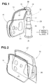
Fig. 1 is a perspective view showing a vehicle door and a weatherstrip-mounting apparatus according to the present invention; -
Fig. 2 is a perspective view of the vehicle door shown inFig. 1 ; -
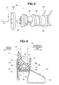
Fig. 3 is an enlarged perspective view of a roller unit shown inFig. 1 >' -
Fig. 4 is a view showing in cross-section a sash of the vehicle door and a weatherstrip mounted on the sash; -
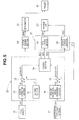
Fig. 5 is an electrical block diagram of a roller control unit ofFig. 1 ; -
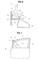
Fig. 6 is a view showing the weatherstrip temporarily attached to the sash; -
Fig. 7 is a view showing that a roller moves along the sash rotating so as to mount the weatherstrip on the sash; -
Fig. 8A is a view showing a comparative example of a principle on the basis of which a weatherstrip is mounted on a sash whileFig. 8B is a view showing a preferred embodiment of a principle on the basis of which a weatherstrip is mounted on a sash; -
Fig. 9A is a view showing a pressing force the roller exerts on a weatherstrip where a sash is not in a slanting position whileFig. 9B is a view showing a pressing force the roller exerts on the weatherstrip where the sash is in the slanting position; and -
Fig. 10 is a perspective view of a prior art apparatus for mounting a soft member. - Referring to
Fig. 1 , there is shown a weatherstrip-mounting apparatus 12 for mounting a weatherstrip (a soft member) 11 on an outer peripheral edge of avehicle door 10. Theapparatus 12 is a robot including abase 15 attached to a floor, arotatable base 16 rotatably mounted on thebase 15, afirst arm 17 attached to thebase 16, asecond arm 18 attached to thefirst arm 17, aroller unit 20 attached to a distal end portion of thesecond arm 18, and aroller control unit 22. - The
roller unit 20 includes aroller 21. Theroller control unit 22 controls both a pressing force of theroller 21 exerted on theweatherstrip 11 and a peripheral speed of a pressedsurface 21a (Fig. 3 ) of theroller 21 pressed against theweatherstrip 11 as theroller 21 presses theweatherstrip 11 so as to mount theweatherstrip 11 to thevehicle door 10. Therotatable base 16, thefirst arm 17, thesecond arm 18 and a pivotal base 28 (Fig. 3 ) jointly constitute a movingunit 23 for moving theroller 21. -
Fig. 2 shows that thevehicle door 10 includes aninner panel 25 located on a passenger-compartment-side, anouter panel 26 attached to an exterior side of theinner panel 25, and asash 27 attached to tops of thepanels weatherstrip 11 is mounted on outer peripheral edges of theinner panel 11 and thesash 27. - As shown in
Fig. 3 , theroller unit 20 includes aforce sensor 32 connected to thepivotal base 28 swingably supported by thesecond arm 18, aservomotor 33 attached to a distal end of theforce sensor 32, and theroller 21 driven by theservomotor 33. The pressedsurface 21a of theroller 21 defines an outer peripheral surface of theroller 21. Theroller 21 is attached to a distal end portion of a roller-supportingshaft 36 attached to a rotational shaft of theservomotor 33. - The
force sensor 32 detects a force directed in a direction along each of three axes (an X axis, a Y axis and a Z axis) perpendicular to each other. It is to be noted that the X axis extends in a direction of extension of the rotational shaft of theservomotor 33 or the roller-supportingshaft 36, the Z axis extends vertically, and the Y axis extends perpendicularly to the X axis and the Z axis. Theforce sensor 32 also detects torque about each of the X axis, the Y axis and the Z axis. Theforce sensor 32 outputs the detected force as a force signal. - The
servomotor 33 has a speed controlled by theroller control unit 22. More specifically, the speed of theservomotor 33 is controlled such that as theroller 21 moves along the edge of thevehicle door 10, a peripheral speed of the pressedsurface 21a of theroller 21 is either equal to a speed of the movement of the roller 21 (the speed of the movement of theroller 21 is generated by the moving unit 23) or higher than the speed of the movement of theroller 12 by a maximum of 10 % of the speed of the movement of theroller 21. -
Fig. 4 shows theweatherstrip 11 mounted on the vehicle door. Thesash 27 includes awall portion 41 located on a vehicle outside, anextension portion 42 horizontally extending from thewall portion 41 towards the passenger-compartment-side, aprojection portion 43 formed at an end portion of theextension portion 42 and located on the passenger-compartment-side, and a U-shapedcross-sectional portion 44 formed on a top of theextension portion 42. The U-shapedcross-sectional portion 44 includes afirst projection portion 46, asecond projection portion 47, and abottom portion 48. - The
weatherstrip 11 includes a fittedportion 51 fitted in the U-shapedcross-sectional portion 44 of thesash 27. Theweatherstrip 11 also includes an outward projectingportion 52, afirst recess portion 53 and afirst lip portion 54 all of which are located on a side of the fittedportion 51 facing towards the vehicle outside. Theweatherstrip 11 further includes asecond recess portion 56 and asecond lip portion 57 that are located on a side of the fittedportion 51 facing towards the passenger-compartment-side. The fittedportion 51 has first andsecond leg portions Reference numeral 63 designates ahollow portion 63. Between thefirst lip portion 54 and thesecond lip portion 57 is located arecess 64. - In mounting the
weatherstrip 11 on thesash 27, theroller 21 presses theweatherstrip 11 with the pressedsurface 21 pressed against therecess 64 of theweatherstrip 11. -
Fig. 5 shows an electrical block diagram of theroller control unit 22. Theroller control unit 22 includes asetting section 71, asubtracter 72, aforce operating section 73, acontrol section 74, a roller peripheralspeed operating section 78 and asubtracter 79. - The
setting section 71 sets a target value F of a pressing force of theroller 21 pressing theweatherstrip 11. Theforce operating section 73 calculates a reaction force R applied to theroller 21 on the basis of a force signal SF output from theforce sensor 32. Thesubtracter 72 calculates a difference ΔF (R-F) between the reaction force R output from theforce operating section 73 and the target value F output from thesetting section 71. The roller peripheralspeed operating section 78 calculates a peripheral speed V2 of the pressedsurface 21a of theroller 21 on the basis of a speed signal SV output from a motorspeed detecting section 77 provided for detecting a speed of theservomotor 33. Thesubtracter 79 compares the peripheral speed V2 calculated by thesection 78 with a speed V1 of movement of theroller 21 along thesash 27 to thereby calculate a difference A V (V2-V1) between the peripheral speed V2 and the speed V1. As will be explained later, the speed V1 is output from asecond driving section 83. Thecontrol section 74 outputs a motor speed controlling signal SC, a first position controlling signal SP1, and a second position controlling signal SP2 on the basis of the difference ΔF output from thesubtracter 72 and the difference ΔV output from thesubtracter 79. - Discussion will be made as to a manner of mounting the
weatherstrip 11 with reference toFig. 6 to Fig. 9B . - Initially, as shown in
Fig. 6 , theweatherstrip 11 is temporarily attached to thesash 27 with thesecond leg portion 62 engaged with thesecond projection portion 47 of the U-shapedcross-sectional portion 44 of thesash 27. At this time, thefirst leg portion 61 of theweatherstrip 11 is put on thefirst projection portion 46 of thesash 27. - Next, as shown in
Fig. 7 , theroller 21 is rotated by the servomotor in a direction of an arrow A while moving on a route provided along thesash 27 in a direction of an arrow B. At this time, theroller 21 presses theweatherstrip 11 temporarily attached to thesash 27, thereby mounting theweatherstrip 11 on thesash 27. - A principle on the basis of which the
roller 21 mounts theweatherstrip 11 on thesash 27 will be discussed in comparison with a comparative example shown inFig. 8A . - Referring to
Fig. 8A , in pressing aweatherstrip 111 to mount the same on asash 112, aroller 110 moves at a speed V1 freely rotating without being fed with power from power source. The movement of theroller 110 at the speed V1 pushes theweatherstrip 111 in a direction of the movement of theroller 110, as shown by an arrow C. As a result, aslack part 113 lifted off thesash 112 is formed in theweatherstrip 111 in front of theroller 110. - In contrast, according to the preferred embodiment of the present invention, as shown in
Fig. 8B , theroller 21 rotates in a direction shown by an arrow D such that a peripheral speed of a roller outer peripheral surface, i.e., the pressedsurface 21a pressed against theweatherstrip 111 is equal to the speed V1 of theroller 21. Alternatively, when theroller 21 reaches at least one part of the route provided along thesash 27, theroller 21 rotates in the direction of the arrow D at a maximum of speed V1 + α (for example, α = 0.1 V1) Otherwise, theroller 21 rotates in the direction of the arrow D at the maximum of the speed V1 + α (for example, α = 0.1 V1) temporarily during the movement of theroller 21 on the route. - The rotation of the roller in the manner shown in
Fig. 8B causes theweatherstrip 11 to move back in a direction shown by an arrow E. As a result, the weatherstrip can be uniformly mounted on thesash 27 without slackening in the direction of the movement of theroller 21. -
Fig. 9A and Fig. 9B illustrate theweatherstrip 11 pressed against thesash 27. - Where the
weatherstrip 11 is mounted on thesash 27 inFig. 9A , theroller 21 is pressed against therecess 64 of theweatherstrip 11 in a direction perpendicular to theextension portion 42 with a pressing force F exerted on therecess 64. Where a sash 91 (identical in structure to the sash 27) slants through an angle θ relative to thesash 27 ofFig. 9A , as shown inFig. 9B , theroller 21 is pressed against therecess 64 in the direction perpendicular to theextension portion 42 such that horizontal and vertical components FH, FV of a pressing force F are exerted on therecess 64. - Discussion will be made as to a manner in which the
roller control unit 22 ofFig. 5 operates when theweatherstrip 11 is mounted on thesash 27. - Referring to
Fig. 5 , so as to set the difference ΔF to zero, thecontrol section 74 outputs the first position controlling signal SP1 to a robot-drivingsection 81 of the weatherstrip-mountingapparatus 12, more specifically, to afirst driving section 82 from which a fist driving signal SD1 is output to the movingunit 23 for driving the movingunit 23 to move theroller unit 20 closely to or away from thesash 27 such that theroller 21 presses theweatherstrip 11 with the pressing force of the target value F exerted on theweatherstrip 11. - The
control section 74 outputs the second position controlling signal SP2 on the basis of which thesecond driving section 83 outputs a second driving signal SD2. Based on this signal SD2, the movingunit 23 moves theroller 21 along thesash 27 at a predetermined speed V1. Thesecond driving section 83 gives thesubtracter 79 such a speed V1. - Further, so as to set the difference ΔV to zero, the
control section 74 outputs the motor speed controlling signal SC to amotor driving section 84 from which a motor driving signal SDM is output to theservomotor 33 to control a speed of theservomotor 33. The peripheral speed V2 of theroller 21 is always equal to the speed V1 as the roller moves on the route provided along thesash 27. Alternatively, the speed V2 becomes higher than the speed V1 (for example, by a maximum of 10 % of the speed V1) at a time theroller 21 reaches at least one part of the route provided along thesash 27, and the speed V1 is equal to the speed V1 as theroller 21 moves on the rest of the route. - As described above, according to the first aspect of the present invention, there is provided a method for mounting the weatherstrip 11 (an elongated soft member) on the substantially-U-shaped-cross-sectional sash 27 (an elongated member) by fitting the
weatherstrip 11 into thesash 27. The method comprises the steps of: temporarily attaching theweatherstrip 11 to thesash 27; and rotating theroller 21 while moving theroller 21 on the route provided along thesash 27 with theroller 21 pressing theweatherstrip 11, such that the pressedsurface 21a of theroller 21 has the peripheral speed V2 (Fig. 5 ) controlled by theroller control unit 22 to be always equal to the speed V1 of the movement of theroller 21 or such that the peripheral speed V2 is higher than the speed V1 by α, (concretely 10 % of the speed V1) at a time theroller 21 reaches at least one part of the route and the speed V2 is equal to the speed V1 as theroller 21 moves on the rest of the route, wherein the pressing force F of the roller exerted on theweatherstrip 11 is controlled by theroller control unit 22 to be always constant as theroller 21 presses theweatherstrip 11. - According to the second aspect of the present invention, there is provided the weatherstrip-mounting
apparatus 12 for mounting theelongated weatherstrip 11 on the substantially-U-shaped-cross-sectional sash 27 by fitting theweatherstrip 11 into thesash 27, as shown inFig. 1 ,Fig. 3 and Fig. 4 . Theapparatus 12 comprises: theroller 21 rotated by the servomotor (an actuator) 33; moving unit (moving means) 23 for moving theroller 21 along thesash 27 with theroller 21 pressing theweatherstrip 11 against thesash 27; theforce sensor 32 disposed between theroller 21 and the movingunit 23 for detecting a reaction force R applied to theroller 21; and thecontrol unit 22 for controlling theroller 21 on the basis of the reaction force R detected by theforce sensor 32, such that a pressing force of theroller 21 to press theweatherstrip 11 is constant while the pressedsurface 21a of theroller 21 has a peripheral speed either equal to a speed of the movement of theroller 21 or higher than the speed of the movement of theroller 21 by a maximum of 10 % of the speed of the movement of theroller 21. - The
roller 21 presses theweatherstrip 11 while rotating such that the peripheral speed V2 of the pressedsurface 21a of theroller 21 is equal to the speed V1 or higher than the speed V1 by a maximum of 10 % of the speed V1 when the roller reaches at least one part of the route. This rotation of theroller 21 prevents theweatherstrip 11 from slackening or stretching in the direction of movement of theroller 21 when theweatherstrip 11 is fitted in thesash 27. Additionally, theforce sensor 32 detects the reaction force applied to theroller 21, such that theroller 21 presses theweatherstrip 11 with the constant pressing force to thereby fit theweatherstrip 11 uniformly in thesash 27. Theweatherstrip 11 thus fitted in thesash 27 has a high quality, and need not repaired nor detached from and again mounted to thesash 27, which improves productivity of the vehicles. - In the illustrated embodiment, the
roller 21 rotates such that the peripheral speed V2 of the pressedsurface 21a of theroller 21 is equal to the speed V1 of the movement of theroller 21 along thesash 27 or higher than the speed V1 by the maximum of 10 % of the speed V1. In another embodiment theforce sensor 32 detects a force acting on theroller 21 in a direction along thesash 27 or a torque acting about the rotational shaft of theroller 21, and the peripheral speed V2 of theroller 21 is controlled on the basis of the detected force or torque to prevent slackening of theweatherstrip 11. - In still another embodiment, as the
roller 21 presses theweatherstrip 11, the peripheral speed V2, after becoming higher than the speed V1 by the maximum of 10 % of the speed V1, may decrease to a speed equal to the speed V1 if necessary. - The method and apparatus for mounting a soft member is suitable for mounting a weatherstrip on a vehicle door.
Claims (2)
- A method for mounting a soft member on an elongated member by fitting the soft member into the elongated member, the elongated member having a substantially U-shaped cross-section, the soft member having an elongated configuration, the method comprising the steps of:temporarily attaching the soft member to the elongated member; androtating a roller while moving the roller on a route provided along the elongated member with the roller pressing the soft member, such that a pressed surface of the roller pressed against the soft member has a peripheral speed either equal to a speed of the movement of the roller or higher than the speed of the movement of the roller by a maximum of 10 % of the speed of the movement of the roller when the roller reaches at least one part of the route,wherein a pressing force of the roller exerted on the soft member is always constant as the roller presses the soft member.
- An apparatus for mounting a soft member on an elongated member by fitting the soft member into the elongated member, the elongated member having a substantially U-shaped cross-section, the soft member having an elongated configuration, the apparatus comprising:a roller rotated by an actuator;moving means for moving the roller along the elongated member with the roller pressing the soft member against the elongated member;a force sensor disposed between the roller and the moving means for detecting a reaction force applied to the roller; anda control unit for controlling the roller on the basis of the reaction force detected by the force sensor, such that a pressing force of the roller to press the soft member is constant while a pressed surface of the roller pressed against the soft member has a peripheral speed either equal to a speed of the movement of the roller or higher than the speed of the movement of the roller by a maximum of 10 % of the speed of the movement of the roller.
Applications Claiming Priority (1)
| Application Number | Priority Date | Filing Date | Title |
|---|---|---|---|
| PCT/JP2005/021394 WO2007057978A1 (en) | 2005-11-16 | 2005-11-16 | Method and device for mounting soft member |
Publications (3)
| Publication Number | Publication Date |
|---|---|
| EP1950125A1 true EP1950125A1 (en) | 2008-07-30 |
| EP1950125A4 EP1950125A4 (en) | 2008-11-26 |
| EP1950125B1 EP1950125B1 (en) | 2009-07-15 |
Family
ID=38048370
Family Applications (1)
| Application Number | Title | Priority Date | Filing Date |
|---|---|---|---|
| EP05809325A Expired - Fee Related EP1950125B1 (en) | 2005-11-16 | 2005-11-16 | Method and device for mounting soft member |
Country Status (6)
| Country | Link |
|---|---|
| US (1) | US8181325B2 (en) |
| EP (1) | EP1950125B1 (en) |
| CN (1) | CN101309828B (en) |
| CA (1) | CA2627553C (en) |
| DE (1) | DE602005015494D1 (en) |
| WO (1) | WO2007057978A1 (en) |
Cited By (4)
| Publication number | Priority date | Publication date | Assignee | Title |
|---|---|---|---|---|
| WO2011134994A1 (en) * | 2010-04-27 | 2011-11-03 | Kuka Laboratories Gmbh | Machining device |
| CN102825461A (en) * | 2012-09-24 | 2012-12-19 | 昆山皇田汽车配件工业有限公司 | Automobile skylight weather strip mistake-proof jig |
| FR2981596A1 (en) * | 2011-10-25 | 2013-04-26 | Renault Sa | TOOL FOR FOOTWEAR |
| WO2020229272A1 (en) * | 2019-05-16 | 2020-11-19 | Thyssenkrupp System Engineering Gmbh | Application unit with pressing force measurement |
Families Citing this family (8)
| Publication number | Priority date | Publication date | Assignee | Title |
|---|---|---|---|---|
| US9120369B2 (en) * | 2011-12-19 | 2015-09-01 | Fca Us Llc | Glass run installation tool |
| CN103935422B (en) * | 2014-04-29 | 2016-04-13 | 神龙汽车有限公司 | The instrument of fast-mounting doorframe sealing band |
| DE102014113509A1 (en) * | 2014-09-18 | 2016-03-24 | Aytec Automation Gmbh | Device for applying a rubber profile |
| DE102016221271B4 (en) * | 2016-10-28 | 2022-02-24 | Ford Global Technologies, Llc | Method and apparatus for applying a flexible seal to the perimeter of a component |
| US11754182B2 (en) * | 2018-05-28 | 2023-09-12 | 9320-2240 Quebec Inc. | System and method for installing seals on support frames |
| JP7345270B2 (en) * | 2019-04-26 | 2023-09-15 | スリーエム イノベイティブ プロパティズ カンパニー | Pasting device, pasting system, and pasting method |
| DE102020118940A1 (en) * | 2020-07-17 | 2022-01-20 | Aytec Automation Gmbh | Device for applying a rubber profile |
| WO2024135944A1 (en) * | 2022-12-19 | 2024-06-27 | 현대자동차주식회사 | Weather strip mounting device |
Family Cites Families (16)
| Publication number | Priority date | Publication date | Assignee | Title |
|---|---|---|---|---|
| DE3541865A1 (en) * | 1985-11-27 | 1987-06-04 | Volkswagen Ag | Device for automatically fitting an elongated material onto a flange |
| US4760636A (en) * | 1986-07-18 | 1988-08-02 | General Motors Corporation | Apparatus of a robot for installing weather stripping in a door or like opening |
| US4715110A (en) * | 1986-07-18 | 1987-12-29 | General Motors Corporation | Apparatus of a robot for installing weather stripping in a door or like opening |
| US4780943A (en) * | 1986-07-18 | 1988-11-01 | General Motors Corporation | Apparatus and method of a robot for installing weather stripping in a door or like opening |
| US5155890A (en) * | 1988-12-20 | 1992-10-20 | Draftex Industries Limited | Apparatus and method for fitting a flexible strip |
| FI900752A7 (en) * | 1989-03-09 | 1990-09-10 | Ferco Int Usine De Ferrures De Batiment | Machine for automatically installing flexible seals, especially external seals, in window gaps |
| US5031293A (en) * | 1989-09-06 | 1991-07-16 | Draftex Industries Limited | Apparatus for fitting a flexible strip |
| US5199154A (en) * | 1990-04-05 | 1993-04-06 | Establissements Mesnel | Method for putting a U-section profile in place on a rim of a frame of a motor vehicle body |
| JPH05200638A (en) * | 1992-01-22 | 1993-08-10 | Mazda Motor Corp | Assembling method and device for small parts |
| US5201106A (en) * | 1992-05-01 | 1993-04-13 | General Motors Of Canada Limited | Apparatus and method of the control of installing weather stripping in a door or like opening by a robot |
| US5487215A (en) * | 1994-02-18 | 1996-01-30 | Multifastener Corporation | Self-adjusting head |
| JPH08155843A (en) | 1994-11-30 | 1996-06-18 | Nishikawa Rubber Co Ltd | Weather strip mounting jig |
| JPH08174353A (en) * | 1994-12-26 | 1996-07-09 | Mitsubishi Motors Corp | Weather-strip mounting device |
| US5875670A (en) * | 1996-07-31 | 1999-03-02 | The Standard Products Company | Tool for roll crimping a flange cover |
| JP2001347976A (en) * | 2000-06-07 | 2001-12-18 | Nishikawa Rubber Co Ltd | Mounting jig and mounting method for weather strip for automobile |
| US7552283B2 (en) * | 2006-01-20 | 2009-06-23 | Qualcomm Incorporated | Efficient memory hierarchy management |
-
2005
- 2005-11-16 US US12/092,104 patent/US8181325B2/en not_active Expired - Fee Related
- 2005-11-16 DE DE602005015494T patent/DE602005015494D1/en not_active Expired - Lifetime
- 2005-11-16 CN CN2005800520645A patent/CN101309828B/en not_active Expired - Fee Related
- 2005-11-16 CA CA2627553A patent/CA2627553C/en not_active Expired - Fee Related
- 2005-11-16 EP EP05809325A patent/EP1950125B1/en not_active Expired - Fee Related
- 2005-11-16 WO PCT/JP2005/021394 patent/WO2007057978A1/en not_active Ceased
Cited By (5)
| Publication number | Priority date | Publication date | Assignee | Title |
|---|---|---|---|---|
| WO2011134994A1 (en) * | 2010-04-27 | 2011-11-03 | Kuka Laboratories Gmbh | Machining device |
| FR2981596A1 (en) * | 2011-10-25 | 2013-04-26 | Renault Sa | TOOL FOR FOOTWEAR |
| CN102825461A (en) * | 2012-09-24 | 2012-12-19 | 昆山皇田汽车配件工业有限公司 | Automobile skylight weather strip mistake-proof jig |
| CN102825461B (en) * | 2012-09-24 | 2014-09-17 | 昆山皇田汽车配件工业有限公司 | Automobile skylight weather strip mistake-proof jig |
| WO2020229272A1 (en) * | 2019-05-16 | 2020-11-19 | Thyssenkrupp System Engineering Gmbh | Application unit with pressing force measurement |
Also Published As
| Publication number | Publication date |
|---|---|
| US20090260211A1 (en) | 2009-10-22 |
| EP1950125A4 (en) | 2008-11-26 |
| CA2627553C (en) | 2010-08-03 |
| WO2007057978A1 (en) | 2007-05-24 |
| CA2627553A1 (en) | 2007-05-24 |
| DE602005015494D1 (en) | 2009-08-27 |
| US8181325B2 (en) | 2012-05-22 |
| EP1950125B1 (en) | 2009-07-15 |
| CN101309828B (en) | 2011-06-08 |
| CN101309828A (en) | 2008-11-19 |
Similar Documents
| Publication | Publication Date | Title |
|---|---|---|
| US8181325B2 (en) | Soft member mounting method and apparatus | |
| US8475611B2 (en) | Method and device for application of a strip material | |
| EP1115589B1 (en) | Strip fitting tool and method of fitting a channel shaped strip | |
| US8516746B2 (en) | Method for self-adaptive regulation of the position of the window pane of a motor-vehicle door with frameless window, and motor-vehicle door provided for said method | |
| US8117728B2 (en) | Method and device for installing open seal | |
| JP2006255788A (en) | Clinch type hemming device using servo motor | |
| JP2006131057A (en) | Flexible member mounting method and mounting apparatus | |
| EP1007273B1 (en) | Strip fitting tools and methods | |
| US10792985B1 (en) | Drain apparatus for use with vehicle sunroofs | |
| US11754182B2 (en) | System and method for installing seals on support frames | |
| US10857862B2 (en) | Dual panel sunroof systems and apparatus for use with vehicles | |
| US10843539B2 (en) | Tensioner apparatus for use with vehicle sunroofs | |
| EP1760235B1 (en) | Device for actuating the rear side windows of a convertible vehicle | |
| JP3132543B2 (en) | Door glass apparatus with assembling position adjusting mechanism and method of adjusting assembling of door glass | |
| EP1743792A2 (en) | Fitting of flexible strips | |
| JP4322783B2 (en) | Method and apparatus for mounting run channel for automobile | |
| JP4482425B2 (en) | Open seal mounting method and mounting device | |
| JP4825575B2 (en) | Run channel mounting method and apparatus | |
| JP4386825B2 (en) | Soft member mounting device | |
| JPH0735126U (en) | Car side door | |
| JP2000288443A (en) | Position adjustment device for opening and closing body |
Legal Events
| Date | Code | Title | Description |
|---|---|---|---|
| PUAI | Public reference made under article 153(3) epc to a published international application that has entered the european phase |
Free format text: ORIGINAL CODE: 0009012 |
|
| 17P | Request for examination filed |
Effective date: 20080416 |
|
| AK | Designated contracting states |
Kind code of ref document: A1 Designated state(s): DE GB |
|
| A4 | Supplementary search report drawn up and despatched |
Effective date: 20081028 |
|
| DAX | Request for extension of the european patent (deleted) | ||
| RBV | Designated contracting states (corrected) |
Designated state(s): DE GB |
|
| GRAP | Despatch of communication of intention to grant a patent |
Free format text: ORIGINAL CODE: EPIDOSNIGR1 |
|
| GRAS | Grant fee paid |
Free format text: ORIGINAL CODE: EPIDOSNIGR3 |
|
| GRAA | (expected) grant |
Free format text: ORIGINAL CODE: 0009210 |
|
| AK | Designated contracting states |
Kind code of ref document: B1 Designated state(s): DE GB |
|
| REG | Reference to a national code |
Ref country code: GB Ref legal event code: FG4D |
|
| REF | Corresponds to: |
Ref document number: 602005015494 Country of ref document: DE Date of ref document: 20090827 Kind code of ref document: P |
|
| PLBE | No opposition filed within time limit |
Free format text: ORIGINAL CODE: 0009261 |
|
| STAA | Information on the status of an ep patent application or granted ep patent |
Free format text: STATUS: NO OPPOSITION FILED WITHIN TIME LIMIT |
|
| 26N | No opposition filed |
Effective date: 20100416 |
|
| PGFP | Annual fee paid to national office [announced via postgrant information from national office to epo] |
Ref country code: DE Payment date: 20101110 Year of fee payment: 6 |
|
| PGFP | Annual fee paid to national office [announced via postgrant information from national office to epo] |
Ref country code: GB Payment date: 20101110 Year of fee payment: 6 |
|
| GBPC | Gb: european patent ceased through non-payment of renewal fee |
Effective date: 20121116 |
|
| REG | Reference to a national code |
Ref country code: DE Ref legal event code: R119 Ref document number: 602005015494 Country of ref document: DE Effective date: 20130601 |
|
| PG25 | Lapsed in a contracting state [announced via postgrant information from national office to epo] |
Ref country code: DE Free format text: LAPSE BECAUSE OF NON-PAYMENT OF DUE FEES Effective date: 20130601 |
|
| PG25 | Lapsed in a contracting state [announced via postgrant information from national office to epo] |
Ref country code: GB Free format text: LAPSE BECAUSE OF NON-PAYMENT OF DUE FEES Effective date: 20121116 |