JP4482425B2 - Open seal mounting method and mounting device - Google Patents
Open seal mounting method and mounting device Download PDFInfo
- Publication number
- JP4482425B2 JP4482425B2 JP2004321255A JP2004321255A JP4482425B2 JP 4482425 B2 JP4482425 B2 JP 4482425B2 JP 2004321255 A JP2004321255 A JP 2004321255A JP 2004321255 A JP2004321255 A JP 2004321255A JP 4482425 B2 JP4482425 B2 JP 4482425B2
- Authority
- JP
- Japan
- Prior art keywords
- roller
- open seal
- flange
- pressing
- force
- Prior art date
- Legal status (The legal status is an assumption and is not a legal conclusion. Google has not performed a legal analysis and makes no representation as to the accuracy of the status listed.)
- Expired - Fee Related
Links
Images


Classifications
-
- B—PERFORMING OPERATIONS; TRANSPORTING
- B23—MACHINE TOOLS; METAL-WORKING NOT OTHERWISE PROVIDED FOR
- B23P—METAL-WORKING NOT OTHERWISE PROVIDED FOR; COMBINED OPERATIONS; UNIVERSAL MACHINE TOOLS
- B23P19/00—Machines for simply fitting together or separating metal parts or objects, or metal and non-metal parts, whether or not involving some deformation; Tools or devices therefor so far as not provided for in other classes
- B23P19/04—Machines for simply fitting together or separating metal parts or objects, or metal and non-metal parts, whether or not involving some deformation; Tools or devices therefor so far as not provided for in other classes for assembling or disassembling parts
- B23P19/047—Machines for simply fitting together or separating metal parts or objects, or metal and non-metal parts, whether or not involving some deformation; Tools or devices therefor so far as not provided for in other classes for assembling or disassembling parts for flexible profiles, e.g. sealing or decorating strips in grooves or on other profiles by devices moving along the flexible profile
Landscapes
- Engineering & Computer Science (AREA)
- Mechanical Engineering (AREA)
- Automatic Assembly (AREA)
- Manipulator (AREA)
- Automobile Manufacture Line, Endless Track Vehicle, Trailer (AREA)
Description
本発明は、自動車のドア取付部開口とドアとの隙間をシールするためにドア取付部開口側に取付けるオープンシールの取付方法及び同取付装置の改良に関するものである。 The present invention relates to a method for attaching an open seal to be attached to a door attachment portion opening side in order to seal a gap between a door attachment portion opening and a door of an automobile, and an improvement of the attachment device.
従来の自動車のドア取付部開口に取付けるシールの取付方法及び取付装置として、産業用ロボット等の自動取付装置によってウェザストリップを取付けるものが知られている(例えば、特許文献1参照。)。
特許文献1の図3を以下の図8で説明する。なお、符号は振り直した。
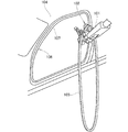
図8は従来のウェザストリップ取付装置を示す斜視図であり、産業用ロボットのアーム101にウェザストリップ取付ヘッド102を装着し、このウェザストリップ取付ヘッド102に設けたローラにウェザストリップ103を掛け、車体104の開口部106に設けたフランジ107にウェザストリップ103を取付けることが示されている。
ウェザストリップ103は、フランジ107に沿って移動するローラでフランジ107に押込まれて取付けられる。
FIG. 3 of Patent Document 1 will be described with reference to FIG. In addition, the code | symbol was reassigned.
FIG. 8 is a perspective view showing a conventional weatherstrip mounting apparatus. A
The
フランジ107にウェザストリップ103をローラで押付けて取付ける場合、ローラの移動する経路をロボットに記憶させておく方法がある。
しかし、この方法では、車体104の設置のずれやフランジ107の製造誤差によって、予め設定しておいた経路でローラを移動させたときに、ローラがフランジ107に対して次第に近づいたり、あるいは次第に離れたりして、ローラでウェザストリップ107を押付ける押付け力が一定でなくなり、ウェザストリップ103をフランジ107に均一に取付けることができなくなる。
また、ローラがフランジ107に沿って移動できなくなり、ローラがウェザストリップ103から外れないようにローラの移動経路を修正する必要がある。
When the
However, in this method, when the roller is moved along a predetermined route due to a deviation in the installation of the
Further, it is necessary to correct the moving path of the roller so that the roller cannot move along the
本発明の目的は、オープンシール取付方法及び同取付装置を改良することで、車体側の設置のずれやフランジの製造誤差を吸収して、オープンシールをドア取付部開口のフランジに均一で且つ精度良く取付けることにある。 The object of the present invention is to improve the open seal mounting method and the mounting device so as to absorb the deviation of the installation on the vehicle body side and the manufacturing error of the flange, and to make the open seal uniform and accurate on the flange of the door mounting opening. It is to install well.
請求項1に係る発明は、自動車のドア取付部開口に設けられたフランジにオープンシールをローラで押付け、嵌合させて取付けるオープンシール取付方法であって、オープンシールをドア取付部開口に設けられたフランジに仮装着し、端部に鍔を設けたローラを、フランジに沿ってオープンシールを押付けながら搬送する際に、ローラに作用する反力を検出し、検出された反力を基に、ローラがオープンシールの背面をフランジ側へ押付ける第1押付け力と、ローラが鍔でオープンシールの車外側の側面を押付ける第2押付け力とを、全押付け時を通じて一定になるように制御することを特徴とする。 The invention according to claim 1 is an open seal mounting method in which an open seal is pressed against a flange provided in a door mounting portion opening of an automobile by a roller and fitted to the flange, and the open seal is provided in the door mounting portion opening. When a roller that is temporarily attached to the flange and is provided with a ridge at the end is conveyed while pressing the open seal along the flange, the reaction force acting on the roller is detected, and based on the detected reaction force, The first pressing force by which the roller presses the back surface of the open seal toward the flange side and the second pressing force by which the roller presses the side surface of the open seal outside the vehicle are controlled so as to be constant throughout the entire pressing operation. It is characterized by that.
ローラに作用する反力を検出し、この反力に基づいてローラがオープンシールの背面をフランジ側へ押付ける第1押付け力を全押付け時を通じて一定になるように制御することで、オープンシールをフランジに均一に嵌合させることが可能になる。また、ローラに作用する反力を検出し、この反力に基づいてローラが鍔でオープンシールの車外側の側面を押付ける第2押付け力を全押付け時を通じて一定になるように制御することで、ローラをオープンシールに沿って精度よく搬送することが可能になる。 By detecting the reaction force acting on the roller and controlling the first pressing force that the roller presses the back of the open seal against the flange side based on this reaction force to be constant throughout the entire pressing, It becomes possible to fit the flange uniformly. In addition, the reaction force acting on the roller is detected, and based on this reaction force, the roller is controlled so that the second pressing force for pressing the side surface of the open seal with the scissors is constant throughout the entire pressing. The roller can be accurately conveyed along the open seal.
請求項2に係る発明は、自動車のドア取付部開口に設けられたフランジにオープンシールをローラで押付け、嵌合させて取付けるオープンシール取付装置において、端部にオープンシールの側面を押付け可能な鍔を設けたローラと、このローラをオープンシールに押付けるとともに搬送する搬送装置と、ローラと搬送装置との間に設けられ、ローラに作用する反力を検出する力覚センサと、この力覚センサにより検出された反力を基に、ローラがオープンシールの背面をフランジ側へ押付ける第1押付け力と、ローラが鍔でオープンシールの車外側の側面を押付ける第2押付け力とが全押付け時を通じて一定になるように搬送装置の駆動を制御する制御装置と、を備えることを特徴とする。 The invention according to claim 2 is an open seal mounting device in which an open seal is pressed against a flange provided in an opening of a door mounting portion of an automobile with a roller and is fitted and mounted. , A conveying device that presses and conveys the roller against the open seal, a force sensor that is provided between the roller and the conveying device and detects a reaction force acting on the roller, and the force sensor The first pressing force that the roller presses the back side of the open seal against the flange side and the second pressing force that presses the outer side of the open seal with the scissors based on the reaction force detected by And a control device that controls driving of the transport device so as to be constant over time.
ローラと搬送装置との間に設けられた力覚センサによって、ローラに作用する反力を検出し、この反力の検出信号に基づいて制御装置で搬送装置の駆動を制御して、搬送装置でローラをオープンシールに押付けるとともにローラをオープンシールに沿って搬送する。このとき、ローラがオープンシールの背面をフランジ側へ押付ける第1押付け力と、ローラが鍔でオープンシールの車外側の側面を押付ける第2押付け力とを全押付け時を通じて一定になるように搬送装置の駆動を制御してオープンシールをフランジに嵌合させる。
ローラの鍔は、オープンシールの車外側の側面を一定の第2押付け力で押付ける。
力覚センサは、第1押付け力と第2押付け力の両方を制御するための反力を検出する。
A reaction force acting on the roller is detected by a force sensor provided between the roller and the conveying device, and the control device controls the driving of the conveying device based on the reaction force detection signal. The roller is pressed against the open seal and the roller is conveyed along the open seal. At this time, the first pressing force by which the roller presses the back surface of the open seal toward the flange side and the second pressing force by which the roller presses the outer side surface of the open seal with the scissors are constant throughout the pressing. The open seal is fitted to the flange by controlling the driving of the conveying device.
The roller collar presses the side surface of the open seal outside the vehicle with a constant second pressing force.
The force sensor detects a reaction force for controlling both the first pressing force and the second pressing force.
請求項1に係る発明では、ローラがオープンシールの背面をフランジ側へ押付ける第1押付け力を全押付け時を通じて一定になるように制御するので、オープンシールをフランジに均一に嵌合させることができ、ドア取付部開口とドアとの間の十分なシール性を確保することができる。 In the invention according to claim 1, since the first pressing force of the roller pressing the back surface of the open seal against the flange side is controlled so as to be constant throughout the pressing, the open seal can be uniformly fitted to the flange. It is possible to secure a sufficient sealing property between the door attachment opening and the door.
また、ローラが鍔でオープンシールの車外側の側面を押付ける第2押付け力を全押付け時を通じて一定になるように制御するので、ローラをオープンシールに沿って精度よく搬送することができ、ローラでオープンシールを常に一定の条件で押付けることができる。
従って、車体の設置のずれやフランジの寸法誤差等を吸収しながら、オープンシールを自動車のドア取付部開口に良好に取付けることができる。
In addition, the roller is controlled so that the second pressing force that presses the outer side surface of the open seal with a scissors is constant throughout the entire pressing, so that the roller can be accurately conveyed along the open seal. The open seal can always be pressed under certain conditions.
Therefore, it is possible to satisfactorily attach the open seal to the door attachment portion opening of the automobile while absorbing deviations in the installation of the vehicle body and dimensional errors of the flange.
請求項2に係る発明では、ローラでオープンシールの背面を一定の第1押付け力で押付け、ローラの鍔でオープンシールの側面を一定の第2押付け力で押付けるように制御装置で搬送装置の駆動を制御するので、搬送装置でローラをオープンシールから外れないように搬送しながらローラでオープンシールをフランジに均一に且つ精度良く嵌合させることができ、車体の設置のずれやフランジの寸法誤差等を吸収しつつオープンシールを自動車のドア取付部開口へ取付けられるオープンシール取付装置を提供することができる。 In the invention according to claim 2, the control device is configured to press the back surface of the open seal with a constant first pressing force with a roller, and press the side surface of the open seal with a constant second pressing force with a roller flange. Since the drive is controlled, the roller can be fitted to the flange evenly and accurately with the roller while conveying the roller so that it does not come off the open seal. It is possible to provide an open seal attachment device that can attach an open seal to an opening of a door attachment portion of an automobile while absorbing the like.
本発明を実施するための最良の形態を添付図に基づいて以下に説明する。なお、図面は符号の向きに見るものとする。
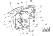
図1は本発明に係るオープンシール取付装置及び自動車の車体を示す斜視図であり、自動車の車体10のドア取付部開口11に設けられたフランジ(不図示)にオープンシール取付装置12でオープンシール13を取付けたことを示す。
ドア取付部開口11は、フロントピラー15、ルーフサイドレール16、センタピラー17、サイドシル18で囲まれた部分である。
The best mode for carrying out the present invention will be described below with reference to the accompanying drawings. The drawings are viewed in the direction of the reference numerals.
FIG. 1 is a perspective view showing an open seal mounting device and a vehicle body of an automobile according to the present invention. An open
The door attachment portion opening 11 is a portion surrounded by the
オープンシール取付装置12は、搬送部21と、オープンシール13を押付けるために搬送部21の先端に取付けた押付け装置22と、この押付け装置22に備えるローラ42をフランジに沿って搬送するときの搬送速度及びローラ42をオープンシール13に押付ける押付け力を制御するローラ搬送速度・押付け力制御装置23(以下、単に「ローラ制御装置23」と記す。)とからなる。
The open
搬送部21は、床に設置したベース部24と、このベース部24に旋回自在に取付けた旋回台25と、この旋回台25にスイング自在に取付けた第1アーム部26と、この第1アーム部26の先端にスイング自在に取付けた第2アーム部27と、この第2アーム部27の先端に取付けるとともに押付け装置22を支持する支持部28とからなり、支持部28に押付け装置22を取付ける。
The
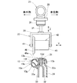
図2は本発明に係るオープンシールの嵌合状態と押付け装置とを示す説明図であり、オープンシール13を取付けるフランジ31は、インナパネル32とアウタパネル33とのそれぞれの縁部32a,33aを接合して形成した部分であり、インナパネル32の内側にはガーニッシュ34が位置する。
FIG. 2 is an explanatory view showing the fitting state of the open seal and the pressing device according to the present invention. The
オープンシール13は、フランジ31に嵌合するコ字断面部13aと、このコ字断面部13aの車室側に延ばすことでガーニッシュ34の縁を覆うインナリップ13bと、コ字断面部13aの車外側に設けた膨出部13cとを一体成形したゴム製のものであり、このオープンシール13によって、ドア取付部開口11(図1参照)とドア(不図示)との隙間をシールする。
コ字断面部13aの背面13d及び膨出部13cの側面13eは、ローラ42で押付ける部分である。なお、13d,13eは膨出部13cの中空部である。
The
The
押付け装置22は、搬送部21の支持部28に取付けた力覚センサ36と、この力覚センサ36にロッド37を介して取付けたローラ支持部38と、このローラ支持部38に支軸41を介して回転自在に取付けたローラ42とからなる。
The
力覚センサ36は、互いに直交する3軸(X軸、Y軸、Z軸であり、例えば、X軸は紙面の表裏方向、Y軸は支軸41の軸方向(図中の矢印Yの方向)、Z軸はロッド37の軸方向(図中の矢印Zの方向)に延びる。)の軸方向の力と、これらのX軸、Y軸、Z軸の各軸回りのトルクを検出するものである。
The
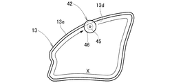
ローラ42は、Y軸方向の軸線を有するローラ本体45と、このローラ本体45の一端に設けた鍔46とからなる。なお、46aは鍔46の外周面を構成するテーパ部である。
ローラ42でオープンシール13をフランジ31に押付けて嵌合するには、ローラ42をフランジ31に沿って図の表裏方向(即ち、X軸方向)に所定速度で移動させながら、ローラ本体45でオープンシール13のコ字断面部13aの背面13dをZ軸方向に一定の押付け力F1で押付けるとともに、ローラ42がオープンシール13から外れないように鍔46でオープンシール13の膨出部13cの側面をY軸方向、詳しくは図の右方に一定の押付け力F2で押付ける。
The
To press the
図3は本発明に係るローラ制御装置のブロック図であり、ローラ制御装置23は、ローラの第1押付け力(図2に示したZ方向の押付け力)の目標値F1を設定する第1力目標値設定部51と、力覚センサ36から出力された力信号SF1に基づいてローラに作用する第1反力FC1(図2に示したZ方向の反力)を演算する第1力演算部52と、目標値F1と第1反力FC1とが入力されて偏差ΔF1(=FC1−F1)を算出する第1減算器53と、ローラの第2押付け力(図2に示したY方向の押付け力)の目標値F2を設定する第2力目標値設定部55と、力覚センサ36から出力された力信号SF2に基づいてローラに作用する第2反力FC2(図2に示したY方向の反力)を演算する第2力演算部56と、目標値F2と第2反力FC2とが入力されて偏差ΔF2(=FC2−F2)を算出する第2減算器57と、これらの偏差ΔF1,ΔF2が入力されて搬送部21(図1参照)の駆動を制御する制御部58とからなる。
FIG. 3 is a block diagram of the roller control device according to the present invention. The
以上に述べたオープンシール取付装置12の作用を図4〜図7で説明する。
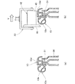
図4(a),(b)は本発明に係るオープンシール取付装置の作用を示す第1作用図である。
(a)において、フランジ31にオープンシール13を仮装着する。
(b)において、搬送部を駆動し、ローラ42をオープンシール13の近傍の所定位置に搬送する。そして、ローラ42を白抜き矢印の方向(Y方向)へ移動させる。
The operation of the open
4 (a) and 4 (b) are first operation views showing the operation of the open seal mounting device according to the present invention.
In (a), the
In (b), the conveying unit is driven to convey the
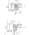
図5(a),(b)は本発明に係るオープンシール取付装置の作用を示す第2作用図である。
(a)において、ローラ42をY方向へ移動させてローラ42の鍔46をオープンシール13の膨出部13cの側面13eに一定の押付け力F2で押付ける。そして、ローラ42を白抜き矢印の方向(Z方向)へ移動させる。
(b)において、ローラ42をZ方向へ移動させてローラ本体45をオープンシール13の背面13dに一定の押付け力F1で押付ける。このとき、押付け力F2は維持した状態にある。
5 (a) and 5 (b) are second operation diagrams showing the operation of the open seal mounting device according to the present invention.
In (a), the
In (b), the
図6は本発明に係るオープンシール取付装置の作用を示す第3作用図である。
ローラ42をオープンシール13の背面13d及び側面13eに押付けた状態で、ローラ42を矢印の方向、即ち、ドア取付部開口のフランジに沿った方向(X方向)へ搬送する。このとき、ローラ42はフリーに回転する。
FIG. 6 is a third operation view showing the operation of the open seal mounting device according to the present invention.
With the
図7は本発明に係るオープンシール取付装置の作用を示す第4作用図であり、図4から図6に述べた内容をフローチャートで表す。なお、STXXはステップ番号を表す。
ST01…フランジにオープンシールを仮装着する。
ST02…ローラをオープンシールの近傍の所定位置に搬送する。
ST03…ローラの鍔でオープンシールの膨出部の側面を一定の押付け力F2で押付ける。
FIG. 7 is a fourth action diagram showing the action of the open seal mounting device according to the present invention, and the contents described in FIGS. 4 to 6 are represented by flowcharts. STXX represents a step number.
ST01 ... Temporarily attach an open seal to the flange.
ST02 ... The roller is conveyed to a predetermined position near the open seal.
ST03 ... The side surface of the bulging portion of the open seal is pressed with a constant pressing force F2 with a roller.
ST04…ローラ本体でオープンシールの背面を一定の押付け力F1で押付ける。
ST05…ローラをオープンシールの背面及び側面に押付けた状態で、ローラをドア取付部開口のフランジに沿った方向へ搬送する。
ST04 ... The back surface of the open seal is pressed with a constant pressing force F1 by the roller body.
ST05 ... With the roller pressed against the back and side surfaces of the open seal, the roller is conveyed in a direction along the flange of the door attachment opening.
次に、以上の図4〜図6で説明した作用を図3に示したローラ制御装置23の側から説明する。
図3において、制御部58は、ロボット駆動部60(ローラをZ方向に搬送する第1駆動部61、ローラをY方向に搬送する第2駆動部62、ローラをX方向に搬送する第3駆動部63からなる)の第1駆動部61に第1位置制御信号SP1を送り、第1駆動部61から搬送部21へ第1駆動信号SD1を送らせてローラ42でオープンシールの背面を一定の押付け力で押付けるように制御する。
Next, the operation described in FIGS. 4 to 6 will be described from the side of the
In FIG. 3, the
また、制御部58は、ロボット駆動部60の第2駆動部62に第2位置制御信号SP2を送り、第2駆動部62から搬送部21へ第2駆動信号SD2を送らせてローラ42でオープンシールの側面を一定の押付け力で押付けるように制御する。
Further, the
更に、制御部58は、ロボット駆動部60の第3駆動部63に第3位置制御信号SP3を送り、第3駆動部63から搬送部21へ第3駆動信号SD3を送らせてローラ42をフランジに沿う方向に搬送するように制御する。
Further, the
以上の図1、図4、図5及び図6に示したように、本発明は第1に、自動車のドア取付部開口11に設けられたフランジ31にオープンシール13をローラ42で押付け、嵌合させて取付けるオープンシール取付方法であって、オープンシール13をドア取付部開口11に設けられたフランジ31に仮装着し、端部に鍔46を設けたローラ42を、フランジ31に沿ってオープンシール13を押付けながら搬送する際に、ローラ42がオープンシール13の背面13dをフランジ31側へ押付ける第1押付け力F1と、ローラ42が鍔46でオープンシール13の車外側の側面13eを押付ける第2押付け力F2とを、全押付け時を通じて一定になるように制御することを特徴とする。
As shown in FIGS. 1, 4, 5, and 6, the present invention firstly presses the
本発明は第2に、図1、図2及び図3に示したように、自動車のドア取付部開口11に設けられたフランジ31にオープンシール13をローラ42で押付け、嵌合させて取付けるオープンシール取付装置12において、端部にオープンシール13の側面13eを押付け可能な鍔46を設けたローラ42と、このローラ42をオープンシール13に押付けるとともに搬送する搬送装置としての搬送部21と、ローラ42と搬送部21との間に設けられ、ローラ42に作用する反力を検出する力覚センサ36と、この力覚センサ36により検出された反力を基に、ローラ42がオープンシール13の背面13dをフランジ31側へ押付ける第1押付け力F1と、ローラ42が鍔46でオープンシール13の車外側の側面13eを押付ける第2押付け力F2とが全押付け時を通じて一定になるように搬送部21の駆動を制御する制御装置としてのローラ制御装置23と、を備えることを特徴とする。
As shown in FIGS. 1, 2, and 3, the present invention secondly opens an
ローラ42がオープンシール13の背面13dをフランジ31側へ押付ける第1押付け力F1を全押付け時を通じて一定になるようにローラ制御装置23で搬送部21の駆動を制御するので、オープンシール13をフランジ31に均一に嵌合させることができ、ドア取付部開口11とドアとの間の十分なシール性を確保することができる。
Since the
また、ローラ42が鍔46でオープンシール13の車外側の側面13eを押付ける第2押付け力F2を全押付け時を通じて一定になるようにローラ制御装置23で搬送部21の駆動を制御するので、ローラ42をオープンシール13に沿って精度よく搬送することができ、ローラ42でオープンシール13を常に一定の条件で押付けることができる。
In addition, since the
従って、車体の設置のずれやフランジの寸法誤差等を吸収しながら、オープンシール13を自動車のドア取付部開口11に均一に且つ精度良く取付けられるオープンシール取付方法及びオープンシール取付装置12を提供することができる。
Accordingly, there is provided an open seal mounting method and an open
本発明のオープンシール取付方法及び同取付装置は、自動車のドア取付部開口にオープンシールを取付けるのに好適である。 The open seal attachment method and the attachment device of the present invention are suitable for attaching an open seal to an opening of a door attachment portion of an automobile.
10…自動車の車体、11…ドア取付部開口、12…オープンシール取付装置、13…オープンシール、13d…オープンシールの背面、13e…オープンシールの側面、21…搬送手段(搬送部)、23…制御装置(ローラ搬送速度・押付け力制御装置)、31…フランジ、36…力覚センサ、42…ローラ、46…鍔、F1…第1押付け力(目標値)、F2…第2押付け力(目標値)、FC1,FC2…反力(第1反力、第2反力)。
DESCRIPTION OF
Claims (2)
前記オープンシールをドア取付部開口に設けられたフランジに仮装着し、
端部に鍔を設けたローラを、前記フランジに沿って前記オープンシールを押付けながら搬送する際に、
前記ローラに作用する反力を検出し、
検出された前記反力を基に、
前記ローラが前記オープンシールの背面を前記フランジ側へ押付ける第1押付け力と、
前記ローラが前記鍔で前記オープンシールの車外側の側面を押付ける第2押付け力とを、
全押付け時を通じて一定になるように制御することを特徴とするオープンシール取付方法。 An open seal mounting method in which an open seal is pressed against a flange provided at an opening of a door mounting portion of an automobile with a roller and fitted to be installed,
Temporarily attach the open seal to the flange provided in the door attachment opening,
When transporting a roller with a ridge at the end while pressing the open seal along the flange,
Detecting a reaction force acting on the roller;
Based on the detected reaction force,
A first pressing force for pressing the back surface of the open seal against the flange side by the roller;
A second pressing force with which the roller presses the outer side surface of the open seal with the scissors,
An open seal mounting method characterized by controlling so as to be constant throughout all pressing.
端部に前記オープンシールの側面を押付け可能な鍔を設けたローラと、
このローラを前記オープンシールに押付けるとともに搬送する搬送装置と、
前記ローラと前記搬送装置との間に設けられ、前記ローラに作用する反力を検出する力覚センサと、
この力覚センサにより検出された反力を基に、前記ローラが前記オープンシールの背面を前記フランジ側へ押付ける第1押付け力と、前記ローラが前記鍔で前記オープンシールの車外側の側面を押付ける第2押付け力とが全押付け時を通じて一定になるように前記搬送装置の駆動を制御する制御装置と、を備えることを特徴とするオープンシール取付装置。 In an open seal mounting device that presses and fits an open seal with a roller to a flange provided at the door mounting portion opening of an automobile,
A roller provided with a flange capable of pressing the side surface of the open seal at the end;
A conveying device that presses the roller against the open seal and conveys the roller;
A force sensor that is provided between the roller and the conveying device and detects a reaction force acting on the roller;
Based on the reaction force detected by the force sensor, the roller presses the back surface of the open seal against the flange side, and the roller touches the side surface of the open seal outside the vehicle with the scissors. An open seal mounting device comprising: a control device that controls driving of the conveying device so that the second pressing force to be pressed is constant throughout the pressing.
Priority Applications (1)
| Application Number | Priority Date | Filing Date | Title |
|---|---|---|---|
| JP2004321255A JP4482425B2 (en) | 2004-11-04 | 2004-11-04 | Open seal mounting method and mounting device |
Applications Claiming Priority (1)
| Application Number | Priority Date | Filing Date | Title |
|---|---|---|---|
| JP2004321255A JP4482425B2 (en) | 2004-11-04 | 2004-11-04 | Open seal mounting method and mounting device |
Publications (2)
| Publication Number | Publication Date |
|---|---|
| JP2006131058A JP2006131058A (en) | 2006-05-25 |
| JP4482425B2 true JP4482425B2 (en) | 2010-06-16 |
Family
ID=36724989
Family Applications (1)
| Application Number | Title | Priority Date | Filing Date |
|---|---|---|---|
| JP2004321255A Expired - Fee Related JP4482425B2 (en) | 2004-11-04 | 2004-11-04 | Open seal mounting method and mounting device |
Country Status (1)
| Country | Link |
|---|---|
| JP (1) | JP4482425B2 (en) |
Families Citing this family (1)
| Publication number | Priority date | Publication date | Assignee | Title |
|---|---|---|---|---|
| ES2726449T3 (en) * | 2011-11-22 | 2019-10-04 | Fft Produktionssysteme Gmbh & Co Kg | Variable and precise strut positioning |
Family Cites Families (1)
| Publication number | Priority date | Publication date | Assignee | Title |
|---|---|---|---|---|
| GB9102042D0 (en) * | 1991-01-30 | 1991-03-13 | Draftex Ind Ltd | Apparatus and method for fitting a flexible strip |
-
2004
- 2004-11-04 JP JP2004321255A patent/JP4482425B2/en not_active Expired - Fee Related
Also Published As
| Publication number | Publication date |
|---|---|
| JP2006131058A (en) | 2006-05-25 |
Similar Documents
| Publication | Publication Date | Title |
|---|---|---|
| CN107433841B (en) | Vehicle door structure | |
| US10946735B2 (en) | Belt assembly for vehicle having hook and swing attachment and associated method | |
| US10752101B2 (en) | Structure of attaching weather strip | |
| WO2008037426A1 (en) | Method and device for application of a strip material | |
| US20070221323A1 (en) | Attaching method of weather strip | |
| JP4376173B2 (en) | Mall mounting method and apparatus | |
| CN101309828B (en) | Installation method and apparatus of flexible member | |
| WO2007060750A1 (en) | Method and device for installing open seal | |
| EP1365935B1 (en) | Sealing and guiding strips | |
| JP2006131058A (en) | Open seal mounting method and mounting apparatus | |
| JP4383319B2 (en) | Flexible member mounting method and mounting apparatus | |
| KR102040933B1 (en) | Cutting device of weather strip for sunroof | |
| JP4453549B2 (en) | Vehicle door seal structure | |
| US20160304144A1 (en) | Door garnish mounting device | |
| JPS5833518A (en) | Position restricting device of vehicular window glass | |
| US11654759B2 (en) | Sealing apparatus for a laterally-sliding door | |
| JPS584624A (en) | Center seal structure for vehicle of sashless door type | |
| JP3714134B2 (en) | Glass run assembly structure | |
| JP2016107681A (en) | Vehicle induced-wind noise reduction device | |
| JP2007296970A (en) | Flexible member mounting method and mounting apparatus | |
| JPH0210017Y2 (en) | ||
| JPH0214966Y2 (en) | ||
| JP2003034147A (en) | Weather strip | |
| JP4322783B2 (en) | Method and apparatus for mounting run channel for automobile | |
| JPH0674780U (en) | Car door |
Legal Events
| Date | Code | Title | Description |
|---|---|---|---|
| A621 | Written request for application examination |
Free format text: JAPANESE INTERMEDIATE CODE: A621 Effective date: 20061130 |
|
| A977 | Report on retrieval |
Free format text: JAPANESE INTERMEDIATE CODE: A971007 Effective date: 20090814 |
|
| A131 | Notification of reasons for refusal |
Free format text: JAPANESE INTERMEDIATE CODE: A131 Effective date: 20090902 |
|
| A521 | Request for written amendment filed |
Free format text: JAPANESE INTERMEDIATE CODE: A523 Effective date: 20091030 |
|
| TRDD | Decision of grant or rejection written | ||
| A01 | Written decision to grant a patent or to grant a registration (utility model) |
Free format text: JAPANESE INTERMEDIATE CODE: A01 Effective date: 20100316 |
|
| A01 | Written decision to grant a patent or to grant a registration (utility model) |
Free format text: JAPANESE INTERMEDIATE CODE: A01 |
|
| A61 | First payment of annual fees (during grant procedure) |
Free format text: JAPANESE INTERMEDIATE CODE: A61 Effective date: 20100319 |
|
| FPAY | Renewal fee payment (event date is renewal date of database) |
Free format text: PAYMENT UNTIL: 20130326 Year of fee payment: 3 |
|
| R150 | Certificate of patent or registration of utility model |
Free format text: JAPANESE INTERMEDIATE CODE: R150 |
|
| FPAY | Renewal fee payment (event date is renewal date of database) |
Free format text: PAYMENT UNTIL: 20130326 Year of fee payment: 3 |
|
| FPAY | Renewal fee payment (event date is renewal date of database) |
Free format text: PAYMENT UNTIL: 20140326 Year of fee payment: 4 |
|
| LAPS | Cancellation because of no payment of annual fees |