EP1949980B1 - Procédé et dispositif de fabrication d'une bande crêpée pour des éléments de connection et de jonction pour bâtiments - Google Patents
Procédé et dispositif de fabrication d'une bande crêpée pour des éléments de connection et de jonction pour bâtiments Download PDFInfo
- Publication number
- EP1949980B1 EP1949980B1 EP07001459A EP07001459A EP1949980B1 EP 1949980 B1 EP1949980 B1 EP 1949980B1 EP 07001459 A EP07001459 A EP 07001459A EP 07001459 A EP07001459 A EP 07001459A EP 1949980 B1 EP1949980 B1 EP 1949980B1
- Authority
- EP
- European Patent Office
- Prior art keywords
- roller
- material web
- region
- longitudinal
- deformable material
- Prior art date
- Legal status (The legal status is an assumption and is not a legal conclusion. Google has not performed a legal analysis and makes no representation as to the accuracy of the status listed.)
- Active
Links
- 239000000463 material Substances 0.000 title claims abstract description 198
- 238000000034 method Methods 0.000 title claims abstract description 42
- 238000004519 manufacturing process Methods 0.000 title claims abstract description 15
- 230000007704 transition Effects 0.000 title claims description 16
- 239000003566 sealing material Substances 0.000 claims description 36
- 230000002093 peripheral effect Effects 0.000 claims description 15
- 238000003825 pressing Methods 0.000 claims description 14
- 229910052782 aluminium Inorganic materials 0.000 claims description 13
- XAGFODPZIPBFFR-UHFFFAOYSA-N aluminium Chemical compound [Al] XAGFODPZIPBFFR-UHFFFAOYSA-N 0.000 claims description 13
- 238000010924 continuous production Methods 0.000 claims description 11
- 229910052751 metal Inorganic materials 0.000 claims description 9
- 239000002184 metal Substances 0.000 claims description 9
- 230000015572 biosynthetic process Effects 0.000 claims description 5
- 239000002985 plastic film Substances 0.000 claims description 3
- 229920006255 plastic film Polymers 0.000 claims description 3
- 238000007493 shaping process Methods 0.000 claims description 3
- 238000005056 compaction Methods 0.000 abstract description 2
- 230000000712 assembly Effects 0.000 description 24
- 238000000429 assembly Methods 0.000 description 24
- 238000007789 sealing Methods 0.000 description 11
- 239000011888 foil Substances 0.000 description 10
- 125000000484 butyl group Chemical group [H]C([*])([H])C([H])([H])C([H])([H])C([H])([H])[H] 0.000 description 9
- 239000011248 coating agent Substances 0.000 description 8
- 238000000576 coating method Methods 0.000 description 8
- 239000010410 layer Substances 0.000 description 6
- 238000010438 heat treatment Methods 0.000 description 5
- 239000004033 plastic Substances 0.000 description 4
- 229920003023 plastic Polymers 0.000 description 4
- 238000012545 processing Methods 0.000 description 4
- 238000009423 ventilation Methods 0.000 description 4
- 239000011449 brick Substances 0.000 description 3
- 239000010408 film Substances 0.000 description 3
- 229920002799 BoPET Polymers 0.000 description 2
- RYGMFSIKBFXOCR-UHFFFAOYSA-N Copper Chemical compound [Cu] RYGMFSIKBFXOCR-UHFFFAOYSA-N 0.000 description 2
- HCHKCACWOHOZIP-UHFFFAOYSA-N Zinc Chemical compound [Zn] HCHKCACWOHOZIP-UHFFFAOYSA-N 0.000 description 2
- 238000005452 bending Methods 0.000 description 2
- 239000002131 composite material Substances 0.000 description 2
- 230000006835 compression Effects 0.000 description 2
- 238000007906 compression Methods 0.000 description 2
- 229910052802 copper Inorganic materials 0.000 description 2
- 239000010949 copper Substances 0.000 description 2
- 238000011161 development Methods 0.000 description 2
- 230000018109 developmental process Effects 0.000 description 2
- 150000002739 metals Chemical class 0.000 description 2
- 230000001681 protective effect Effects 0.000 description 2
- 239000007858 starting material Substances 0.000 description 2
- 239000002966 varnish Substances 0.000 description 2
- 229910052725 zinc Inorganic materials 0.000 description 2
- 239000011701 zinc Substances 0.000 description 2
- 229910052684 Cerium Inorganic materials 0.000 description 1
- NIXOWILDQLNWCW-UHFFFAOYSA-N acrylic acid group Chemical group C(C=C)(=O)O NIXOWILDQLNWCW-UHFFFAOYSA-N 0.000 description 1
- 230000006978 adaptation Effects 0.000 description 1
- 239000000853 adhesive Substances 0.000 description 1
- 230000001070 adhesive effect Effects 0.000 description 1
- 239000012790 adhesive layer Substances 0.000 description 1
- AZDRQVAHHNSJOQ-UHFFFAOYSA-N alumane Chemical class [AlH3] AZDRQVAHHNSJOQ-UHFFFAOYSA-N 0.000 description 1
- 238000003491 array Methods 0.000 description 1
- 239000012876 carrier material Substances 0.000 description 1
- GWXLDORMOJMVQZ-UHFFFAOYSA-N cerium Chemical group [Ce] GWXLDORMOJMVQZ-UHFFFAOYSA-N 0.000 description 1
- 239000003086 colorant Substances 0.000 description 1
- 238000010276 construction Methods 0.000 description 1
- 239000013039 cover film Substances 0.000 description 1
- 238000005336 cracking Methods 0.000 description 1
- 238000007599 discharging Methods 0.000 description 1
- 238000009413 insulation Methods 0.000 description 1
- 239000004922 lacquer Substances 0.000 description 1
- 239000000203 mixture Substances 0.000 description 1
- 239000003973 paint Substances 0.000 description 1
- 230000035515 penetration Effects 0.000 description 1
- 229920000139 polyethylene terephthalate Polymers 0.000 description 1
- 238000011084 recovery Methods 0.000 description 1
- 238000004904 shortening Methods 0.000 description 1
- 238000012360 testing method Methods 0.000 description 1
- 238000012546 transfer Methods 0.000 description 1
- XLYOFNOQVPJJNP-UHFFFAOYSA-N water Substances O XLYOFNOQVPJJNP-UHFFFAOYSA-N 0.000 description 1
Images


Classifications
-
- B—PERFORMING OPERATIONS; TRANSPORTING
- B21—MECHANICAL METAL-WORKING WITHOUT ESSENTIALLY REMOVING MATERIAL; PUNCHING METAL
- B21D—WORKING OR PROCESSING OF SHEET METAL OR METAL TUBES, RODS OR PROFILES WITHOUT ESSENTIALLY REMOVING MATERIAL; PUNCHING METAL
- B21D13/00—Corrugating sheet metal, rods or profiles; Bending sheet metal, rods or profiles into wave form
- B21D13/04—Corrugating sheet metal, rods or profiles; Bending sheet metal, rods or profiles into wave form by rolling
- B21D13/045—Corrugating sheet metal, rods or profiles; Bending sheet metal, rods or profiles into wave form by rolling the corrugations being parallel to the feeding movement
-
- B—PERFORMING OPERATIONS; TRANSPORTING
- B21—MECHANICAL METAL-WORKING WITHOUT ESSENTIALLY REMOVING MATERIAL; PUNCHING METAL
- B21D—WORKING OR PROCESSING OF SHEET METAL OR METAL TUBES, RODS OR PROFILES WITHOUT ESSENTIALLY REMOVING MATERIAL; PUNCHING METAL
- B21D13/00—Corrugating sheet metal, rods or profiles; Bending sheet metal, rods or profiles into wave form
- B21D13/04—Corrugating sheet metal, rods or profiles; Bending sheet metal, rods or profiles into wave form by rolling
Definitions
- the invention relates to a method for producing a creped material according to the preamble of claim 1, in particular a sealing material for connections and transitions to buildings, which is provided with creases flat and a wheel assembly for introducing L josswelLen in a deformable material web according to the preamble of claim 11, and a wheel assembly for compacting a longitudinal-wave having web as defined in claim 14.
- EP-A-1 634 660 discloses a method and apparatus for forming striped structures in a ribbon material.
- Connections and transitions to buildings refer to the following introduced on the roof roofing materials of any kind, especially roof tiles and bricks, and towering sections of buildings such as in particular fireplaces, windows and dormer windows.
- transition areas between different components This is the case, for example, in chimneys, roof windows or dormer windows.
- the formation of such a building part in the region of the roof prevents, for example, a continuous laying of the applied roof tiles. Consequently, the area of the transition between the overlying the roof of the building and the part of the building adjacent roof tiles must be sealed. The transition areas must be closed air and water tight.
- sealing strips are used, which are plastically deformable and can be adapted to the sealed transition areas.
- plastic deformable sealing material deformable material webs have been found which have Kreppfalten.
- Kerppfalten is initially understood to mean undulating creases in a creped form.
- the deformable starting material is creased during creping, which have much smaller lengths and widths in relation to the material dimension.
- the creping causes a shortening of the web in the direction perpendicular to the extension of the crepe creases and thus an increased extensibility of the creped product compared to the starting material.
- the invention provides in a surprisingly simple way the ability to produce a creped material which is provided with Kreppfalten, the Kreppfalten in different directions over this hiraus can be introduced over substantially the entire surface of the material.
- the production of the creped material provided, in particular, flatly with crepe creases can advantageously be carried out continuously.
- the invention offers the advantage of being able to produce the material provided with crepe creases in a continuous process by the material web during the process the implementation of steps b1) to d) in the direction of their Hauptausdehnungsraum, in particular continuously, is promoted.
- the introduction of the longitudinal profiling and / or the introduction of the transverse profiling and / or the pressing takes place continuously.
- the invention provides the advantage to be able to maintain the production of the railway in its main direction of expansion during the whole procedure. This is achieved in that according to a particularly advantageous embodiment when introducing the longitudinal profiling the deformable material web in step b1) or in steps b1) and b2) is provided from the inside out with waves.
- the invention also offers the possibility of being able to process as deformable material web also those materials in which no permanent shaping by deformation in the cold state (cold deformation) can take place.
- the deformable material web is heated during the introduction of the longitudinal profiling.
- heating to a temperature in the range between 50 ° C. and 200 ° C., preferably to a temperature in the range between 100 ° C. and 150 ° C.
- the temperature can vary depending on which Material is used for the deformable material web to be selected.
- a metal foil which in particular comprises aluminum
- a metal foil web is provided as a deformable material web.
- Particularly suitable materials for the deformable material web are metals such as aluminum and / or zinc and / or copper and / or lead and galvanized films and / or deformable plastics and composite materials of such materials.
- a metal foil laminated with a plastic film can be provided as a deformable material web.
- a metal foil which comprises aluminum can be used as the metal foil.
- the inventive method is carried out such that by the deformation of the material web in steps b1) to d) a material supply in the material web is created, which allows a recovery, after the dimension of the material web in the longitudinal direction and / or in the transverse direction by at least 10th %, advantageously by at least 30%, preferably by up to 80%, is greater in relation to the dimension which the material web had reached in the longitudinal direction and / or in the transverse direction according to section d).
- the extensibility of the sealing material produced by the method according to the invention is thus in the range between about 10% and about 80%.
- Another advantage of the sealing material produced by the method according to the invention is that it consists of only one layer and then can already meet all requirements. Creping enables the simple, rapid and precise adaptation of the sealing material produced by the method according to the invention to differently structured surfaces of components on buildings. At the same time, the sealing material according to the invention is particularly well suited to the permanent formation of a deformed state, since it shows substantially no creep behavior.
- the invention further provides a wheel assembly for introducing longitudinal shafts in a deformable material web with the features of claim 11.
- the wheel assembly comprises a first and a second wheel, each having a rotation axis, which can be rotatably mounted and has a running surface with at least partially wave-shaped profile.
- the waves run along the circumferential direction of the tread.
- the tread comprises a central region to which a side region joins on each side.
- a lateral line is defined. wherein the center line and the side line are parallel to the axis of rotation of the wheel.
- the distance ⁇ M 1 of the center line to the rotation axis is larger than the distance ⁇ S 1 of the sideline to the rotation axis
- the distance ⁇ M 2 of the center line to the rotation axis is smaller than the distance ⁇ S 2 of the sideline to the rotation axis, so in that the middle region of the first wheel defines at least one projection and the middle region of the second wheel forms at least one receptacle for the projection of the first wheel, when the two wheels roll with one another during operation with their running surfaces.
- the first and the second wheel are formed such that the wave crests and wave troughs of the wave-shaped profile have a substantially semicircular cross-section. Due to the associated symmetry, the production of mutually corresponding profiles of the running surfaces of the wheels is advantageously simplified.
- the side regions of the second wheel comprise a cylindrical region adjoining the wave crest, whose lateral surface extends parallel to the axis of rotation, so that during operation of the wheel assembly the wave crest can roll in the lateral region of the first wheel on the cylindrical region in the side region of the second wheel ,
- the wheel arrangement for introducing longitudinal shafts into a deformable material web is designed such that the wave crests, wave troughs and cylindrical regions have substantially the same width measured parallel to the axis of rotation of the wheel.
- the width of the wave crests, wave troughs and cylindrical regions is in particular less than about 2 cm and is preferably in the range of about 0.1 cm to about 1 cm, more preferably about 0.5 cm.
- the first and second wheels of the wheel assembly for introducing longitudinal shafts into a deformable material web can, for example, have a width measured parallel to the axis of rotation of less than approximately 10 cm, preferably in the range of approximately 0.5 cm to approximately 5 cm, particularly preferably approximately 2 cm exhibit.
- the wheels may in particular have a diameter measured at the greatest extent perpendicular to the axis of rotation of less than approximately 20 cm, preferably in the range of approximately 1 cm to approximately 10 cm.
- the size, in particular the diameter, the thickness or the dimensions of the profiling of the wheels determines the penetration depth during the deformation of the material web.
- the appropriate dimensions will be According to the invention chosen so that the desired extensibility is adjusted by the deformation.
- the distance between the center line and the side line is less than approximately 2 cm and is preferably in the range from approximately 0.1 cm to approximately 1 cm, particularly preferably approximately 0.5 cm.
- the areas of the deformable material web which are located laterally of the already deformed region and which are not yet or not yet deformed are guided by the arrangement of the two wheels relative to one another and the shaping with the mutually corresponding enveloping surfaces in a substantially flat surface between the two wheels. Due to the contact with the profiled peripheral surface of the wheels, the longitudinal profiling is compressed when passing through the wheel assembly for compressing a longitudinal waves having material web. This creates in cross-section an ⁇ -shaped profile of the deformable material web.
- the surface of a side region on the first wheel runs parallel to the surface of a corresponding side region on the second wheel, so that a gap is formed between the wheels which has a substantially constant width.
- the central region of a wheel has a central region which comprises a recess for receiving at least a portion of a shaft in the longitudinal waves having material web, so that when passing through the longitudinal waves having material web through the wheels assembly for compressing a longitudinal waves having web Bulge of the ⁇ -shaped profile is formed.
- the wheels of the wheel arrangement for compacting a material web having longitudinal waves can, for example, have a width measured parallel to the axis of rotation of less than approximately 10 cm, preferably in the range of approximately 0.5 cm to approximately 4 cm, particularly preferably approximately 1.7 cm.
- the wheels have a diameter measured at the greatest extent perpendicular to the axis of rotation less than about 20 cm, preferably, they have a diameter in the range of about 1 cm to about 7 cm, more preferably of about 3.5 cm.
- the width of the side regions of the wheels of the wheel arrangement for compacting a material web having longitudinal waves is less than approximately 1 cm and is preferably in the range from approximately 0.05 cm to approximately 0.5 cm, particularly preferably approximately 0, 25 cm.
- the width of the central region may be less than about 4 cm ir further development of the inventive wheel assembly for compressing a longitudinal waves having material web and is preferably in the range of about 0.1 cm to about 4 cm.
- the recess is in cross-section advantageously circular arc-shaped, in particular substantially semicircular.
- the radius of the arc, in particular of the semicircle, which form the depression with a circular-arc, in particular semicircular, cross-section is in particular less than about 2 cm and is preferably in the range of about 0.1 cm to about 1 cm, particularly preferably about 0.5 cm.
- the invention further provides a tandem wheel assembly which combines a wheel assembly for introducing longitudinal shafts into a deformable web and a wheel assembly for compacting a longitudinal web having material web according to the invention, the two wheel assemblies being deformable in relation to the conveying direction in operation Material web is conveyed through the tandem wheel assembly, are arranged in alignment one behind the other, that in operation, the longitudinal shaft formed in the wheel assembly runs in the wheel assembly through the profiled peripheral surfaces.
- the invention further provides an apparatus for use in the continuous production of a creped material comprising a plurality of wheel assemblies according to the invention for introducing longitudinal shafts into a deformable material web which are arranged along a conveying direction of a deformable material web running through the apparatus in operation.
- a device which comprises a plurality of wheel arrangements for compressing a longitudinal waves deformable material web according to the invention, which are arranged along a conveying direction of a running through the device deformable material web.
- the invention provides an apparatus for use in the continuous manufacture of a creped material comprising a plurality of tandem wheel assemblies arranged along one Conveying direction of a current running through the device deformable material web are arranged.
- the orientation of the individual wheel assemblies or tandem wheel assemblies in relation to each other in the devices depends on the desired objective of the treatment of the deformable material web in the respective device. If longitudinal shafts are to be introduced into the deformable material web from the inside out, the invention provides that in the device for use in the continuous production of a creped material, the wheel assemblies or tandem wheel assemblies are arranged substantially V-shaped and / or substantially U-shaped are.
- the device according to the invention may comprise at least three wheel arrangements for introducing longitudinal shafts into a deformable material web, wherein the wheel assemblies are positioned V-shaped or U-shaped relative to each other.
- the invention also provides an apparatus for use in the continuous manufacture of a creped material comprising at least three gear assemblies for compacting a longitudinal path material web, the gear assemblies being positioned V-shaped or U-shaped relative to one another.
- the V-shaped or U-shaped or similar arrangement is preferably oriented mirror-symmetrically to the conveying direction of the deformable material web through the device, so that the introduction or compression of longitudinal waves from the inside to the outside is made possible with respect to the deformable material web.
- the invention provides in a further embodiment that the wheel arrangements or the tandem wheel arrangements are arranged on a line which runs obliquely to the conveying direction.
- the invention provides an apparatus for use in the continuous production of a creped material, which comprises at least three wheel assemblies for introducing longitudinal shafts in a deformable material web and at least three gear assemblies for compressing a longitudinal waves material web, wherein in each case a wheel assembly for introducing Llveswelien form a tandem wheel assembly in a deformable material web and a wheel assembly for compressing a longitudinal waves having material web and the at least three tandem wheel arrays are positioned V-shaped to each other.
- the invention thus also provides an apparatus for continuously producing a creped material comprising at least one means for continuously feeding a deformable material, at least one apparatus for continuously introducing a longitudinal profiling into the deformable material as described above, a continuous pressing apparatus the material for producing a material having pressed longitudinal shafts and means for continuously discharging the material with pressed longitudinal shafts.
- the method according to the invention is intended to provide a sealing material, by the use of the sealing of connections and transitions, in particular between over-roof components, the craftsman on the one hand made easy and fast and on the other hand a consistently good and reproducible quality of the seal can be achieved.
- the structure of the sealing material is designed so that a material supply is created by creping, which makes the sealing strip stretchable.
- the elasticity is approximately in the range of 10% to 80%.
- Another advantage of the sealing material produced by the method of the invention is that it consists of only one layer and can already meet all requirements.
- the invention makes it possible to dispense with a carrier material made of an expanded metal grid insert. This results in significant advantages over known sealing materials in terms of production efficiency, the price of the product and the workability of the sealing material.
- the sealing material can be developed in such a way that the crepe creases run parallel and / or in different directions.
- the sealing material according to the invention can be manufactured as very different materials dier and is thus adaptable to versatile requirements.
- deformable plastics, metals, in particular aluminum, zinc and / or copper as well as lead and / or galvanized films can be used.
- the sealing material may have a bondable coating on its underside.
- a high flexibility of the attached to the underside adhesive element is provided so that the sealing material can be pulled around corners and edges, without the use of additional folding devices is necessary.
- a proper and high-quality sealing even difficult to seal transitions can be achieved.
- an insulating layer can also be applied to the underside of the sealing material so as to simultaneously enable thermal insulation.
- the sealing material may be provided on its upper side with a coating.
- the coating may in particular contain a lacquer.
- the coating can furthermore be weather-resistant and / or UV-impermeable, so that the sealing material withstands a wide variety of stresses permanently.
- the sealing material can be used to build the ridge and burr ventilation element.
- the sealing material is provided for this purpose in a strip, which can be provided in a central region of the ridge and burr ventilation elements with ventilation holes.
- side parts made of the sealing material can be attached to an air-permeable, but for rain and flight snow impermeable middle part.
- the air-permeable middle part can be placed on the roof ridge or on ridges, and the side parts can be molded onto the adjoining roof tiles so as to provide a sealed transition from the ridge or a ridge to the bricks.
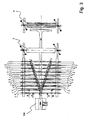
- FIGS. 1 and 2 as well as in the Figures 3 and 4 is an overview of the individual processing steps in carrying out the method according to the invention shown.
- the FIGS. 1 and 2 show the corresponding devices in side view, and the Figures 3 and 4 represent the associated supervision.
- a deformable material web 9 is fed to the device 102.
- the deformable material web 9 has a Schoausdehnungsraum 90.
- the deformable material web 9 is conveyed in the illustrated embodiment of the invention continuously in its Schoausdehnungsraum 90 during the implementation of the method according to the invention.
- the Hauptausdehnungsraum is thus equal to the conveying direction of the web.
- deformable material web for example, aluminum foil can be used.
- deformable material web laminated with a plastic foil aluminum foil As a deformable material web, for example, aluminum foil can be used.
- the deformable material web 9 is curled when passing through the device 102 via individual rollers from inside to outside in its longitudinal direction, that is, in the main expansion direction 90.
- the individual wheels are shown, which are used in the individual steps from the introduction of the longitudinal curl to the longitudinally creped material.
- the deformable material web 9 When passing through the device 102, the deformable material web 9 is heated in the exemplary embodiment shown.
- a hot air supply 105 is provided, which provides heated air, which is passed to the deformable material web 9 during the introduction of longitudinal shafts and the introduction of transverse waves.
- the supply of hot air for heating the deformable material may, depending on which materials are selected for the web 9, from below and / or from above when introducing the longitudinal shafts or the Transverse waves take place.
- the temperature of the deformable material web increases to values between, for example, 100 and 150.degree.
- thermoforming material webs 9 By the supply of heat, a deformation of such material webs 9 is made possible in a simple manner, which have a high resilience, so that a cold deformation is not possible.
- a heating to temperatures between 100 and 150 ° C is particularly advantageous when used with a plastic film laminated aluminum foil as a deformable material web 9.
- a hot air supply 105 for example, a fan with motor and heating can be used.
- the device 102 comprises a device 101 with in the example shown seventeen wheel assemblies 1 for introduction of longitudinal shafts and a device 102 with seventeen wheel assemblies 2 in the example shown for compressing the longitudinal shafts, wherein in each case a wheel arrangement 1 for introducing longitudinal shafts and a wheel assembly 2 for Compaction of longitudinal shafts in the main extension direction 90 of the deformable material 9 are arranged behind each other and form a tandem wheel assembly.
- the tandem wheel assemblies and the wheel assemblies 1 and the wheel assemblies 2 are in the illustrated embodiment, V-shaped positioned to each other.
- the V-shaped positioning of the tandem wheel assemblies is in the top view (see FIG. 3 ) to recognize the device 102 particularly well.
- the deformable material web 9 When passing through the wheel assembly 1, the deformable material web 9 is provided with longitudinal shafts 91, which extend parallel to the main extension direction 90.
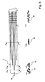
- FIG. 5 is the deformable material web 9 when passing in the FIGS. 1 and 3 shown device shown in plan. Furthermore, cutouts are shown in cross-section from a view illustrating the various processing stages of the deformable web.
- the deformable material web 9 After passing through the wheel assembly 1, the deformable material web 9 is provided with longitudinal shafts 91, which extend parallel to the main extension direction 90, the deformable material web 9. When passing through the wheel assembly 2, the longitudinal shafts 91 are compressed, so that a ⁇ -shaped profile 92 is formed. After the deformable material web 9 has been provided in the device 102 substantially over its entire width with longitudinal shafts 91 which are compressed to the ⁇ -shaped profile 92, the web with the profile 92 enters the first pressing plant 3.
- the web 9 passes through a nip between rubberized rollers 30 and 300, the embossment 92 being deformed back and the material being pleated.
- the result is a profile of flat-pressed longitudinal shafts 93.
- the thus provided in the longitudinal direction with Kreppfalten web enters the profile 93 in a second press shop 4 a.
- the deformable material web 9 is impressed with a transverse pleating.
- the deformable material web is provided in the illustrated embodiment substantially perpendicular to its main extension direction with transverse shafts 94.
- the armor 5 is an apparatus for continuously pressing at least a portion of at least one profiled web with a pressing device having a in the conveying direction of the web 9 to be pressed tapered press nip predetermined width and length, and at least one rotating press belt, which each can rotate over two rollers.
- a pressing device having a in the conveying direction of the web 9 to be pressed tapered press nip predetermined width and length, and at least one rotating press belt, which each can rotate over two rollers.
- Such a device is the subject of the German patent DE 102 41 230 of the applicant. After the folding of the film 9 in the devices 102, 3, 4 and 5, a material supply of, in the illustrated embodiment, about 80% results in the longitudinal and in the transverse direction.
- the creped material 95 is provided with an adhesive layer in a third press shop 6.
- a butyl tape is applied to the material, for example to the folded aluminum foil 9, from the bottom over all or part of the area.
- the butyl tape can be covered with a cover film.
- a butyl feed 7 is provided, from which the butyl tape is fed to the butyl press in the third press shop 6.
- the creped material is bonded to the butyl tape.
- the finished product is then wound on a reeling machine 8 to form so-called infinite rolls. For example, rolls can be made on which a creped material of 5 m in length is rolled up.
- a deformable material 9 is profiled in at least two directions, for example in the longitudinal direction and in the transverse direction, as described above.
- the profiling in the transverse direction is possible in a relatively simple manner using two profile rollers in the second press shop 4.
- the longitudinal profiling takes place parallel to the conveying direction of the web 9 in order to feed the longitudinally profiled web to the transverse profiling in a downstream working step can.
- the transverse profiling and subsequently the longitudinal profiling is carried out in a first step.
- the total conveying speed with which the deformable material 9 is introduced into the device 102, passed through the device 102, through the first press shop 3 and the second press shop 4 and the armor 5 and the third press shop 6 to the reeling 8 is performed, constant.
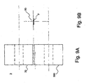
- a wheel assembly 1 For continuously introducing longitudinal shafts 91 into the deformable material web 9, a wheel assembly 1 is provided. Such a wheel assembly is shown schematically in FIG Figure 8A shown.
- the wheel assembly 1 comprises a first Wheel 10 and a second wheel 100.
- the first wheel 10 has a profiled tread 16 and is rotatably supported about a rotation axis 11.
- the second wheel 20 has a profiled running surface 160 and is rotatable about an axis of rotation 110 storable.
- the first wheel 10 includes a central region 17, followed by side regions 18 on the right and left.
- the running surface 16 has a wave-shaped profile, wherein the waves, along the circumferential direction of the tread 16, extend.
- the outer boundary of the central region 17, which is radially seen from the axis of rotation 11, defines a center line 12 of the first wheel 10.
- the outer boundary cerium regions 18, defined radially from the axis of rotation 11, defines a lateral line 13 between the center line 12 and the axis of rotation 11 first wheel 10 a distance .DELTA.M 1 . Between the side line 13 and the axis of rotation 11 there is a distance ⁇ S 1 in the first wheel 10.
- the side regions 18 of the first wheel 10 comprise a wave trough 19 and a wave crest 15, the wave trough 19 adjoining the central region 17.
- the first wheel 10 has a projection 14.
- the distance ⁇ M 1 is greater than the distance ⁇ S 1 , so that the difference of the distances ⁇ M 1 and ⁇ S 1 defines the height of the projection 14.
- the second wheel 100 has a central region 170, on both sides of which side regions 180 join.
- the outer boundary of the middle region 170 which is seen radially from the rotation axis 110, defines a center line 120.
- a Distance ⁇ M 2 Between the center line 120 and the rotation axis 110 of the second wheel 100 is a Distance ⁇ M 2 .
- the second wheel 100 comprises in its side regions 180 a wave crest 119 and a cylindrical region 115, wherein the wave crest 119 adjoins the central region 170.
- the central region 170 has a depression.
- the distance ⁇ S 2 is greater than the distance ⁇ M 1 , so that the difference of the distances defines the depth of the recess in the central region 170.
- the height of the projection 14 of the first wheel 10 is substantially equal to the depth of the recess in the second wheel 100, so that the recess in the central region 170 of the second wheel 100 forms a receptacle 114 for the projection 14 of the first wheel, if In operation of the wheel assembly 1, the profiled running surfaces 16 of the first wheel 10 and 160 of the second wheel 100 engage with each other and roll against each other.
- the wave crests 14, 15 and 119 and the wave troughs 19 and 114 of the wheel assembly 1 have a substantially semicircular cross-section.
- the resulting when passing through the deformable material web 9 by the wheel assembly 1 profile 91 is in FIG. 8B on the same scale as the wheel assembly 1, which in Figure 8A shown is shown.
- the wheel assembly 2 for compressing longitudinal shafts comprises a first wheel 20 and a second wheel 200.
- the first wheel 20 has a profiled peripheral surface 27 and is rotatably supported about a rotation axis 21.
- the profiled circumferential surface 27 is enclosed by an envelope surface 26, which is the lateral surface of a cylinder about the rotation axis 21, of the first wheel 20, which contacts the profiled circumferential surface 27 at its point radially farthest from the rotation axis 21.
- the second wheel 200 has a profiled circumferential surface 270 and is rotatable about an axis of rotation 210 storable.
- the second wheel 200 has an envelope surface 260 that encloses the profiled peripheral surface 270.
- the envelope surface 260 is a circumferential surface of a cylinder about the rotation axis 210 of the second wheel 200, which contacts the profiled peripheral surface 270 at its radially farthest from the rotation axis 210 point.
- the envelope surface 26 of the first wheel 20 rolls on the envelope surface 260 of the second wheel 200.
- the profiled peripheral surfaces 27 and 270 of the first wheel 20 and the second wheel 200 are formed so that a continuous gap is defined between the wheels of the wheel assembly 2 for compressing longitudinal shafts.
- the first wheel 20 comprises a central region 23, to which side regions 23 adjoin on both sides.
- the second Wheel 200 includes a central region 280, followed by side regions 230 on either side.
- the middle portion 28 of the first wheel 20 is cylindrically shaped with respect to the rotation axis 21.
- the central region 280 of the second wheel 200 is disposed adjacent to the central region 28 of the first wheel.
- the central portion 280 of the second wheel 200 includes a central portion 281.
- a recess 214 is formed in the central portion 281.
- the inner boundary of the recess 214 which is radially seen from the rotation axis 210, defines a distance ⁇ V between the lowest point of the recess 214 and the axis of rotation 210.
- the distance ⁇ V is greater than the distance ⁇ M 2 in the second wheel 100 of the wheel assembly 1 for introducing longitudinal shafts 91.
- the wheel assembly 1 and the wheel assembly 2 form a tandem wheel assembly.
- the two wheel assemblies 1, 2 with respect to the Hauptausdehnungsraum the deformable material web, so the conveying direction 90, arranged in alignment one behind the other that during operation formed in the wheel assembly 1 on the projection 140 longitudinal shaft 91 in the wheel assembly is guided by the profiled peripheral surfaces 27, 270, in particular by the recess 214.
- the first press shop 3 comprises a first roller 30 and a second roller 300, which can be rotatably supported by spaced apart from each other.
- the compressed longitudinal profiling 92 is compressed, so that a compressed longitudinal profiling 93 is formed, as in FIG. 9B , corresponding to the in Figure 9A shown dimensions of the first press shop 3, is shown.
- the creped material can either be used directly or further processed into a weather strip.
- a sealing strip comprises a sealing material which has a bondable coating on its underside. This coating may be, for example, a butyl tape.
- the sealing material is provided with flat Kreppfalten. The crevices may be unevenly arranged so that the material can be easily pulled apart in all directions.
- the sealing material may, for example, be designed as an aluminum strip, one side of which is colored is coated and the other side is laminated against a PET film.
- the layer structure comprises 8.0 ⁇ 1.7 g / m2 of protective varnish, for example brick red protective varnish (acrylic base). Furthermore, the layer structure comprises an aluminum tape having a thickness of 70.0 ⁇ 5.6 micrometers, a paint coating of 3.0 ⁇ 0.9 g / m2 and a PET film having a thickness of 23 ⁇ 2.3 micrometers ,
- the bond strength between aluminum and PET foil is more than 5 N / 15 mm. This indication means that a strip of 15 mm width is subjected to cracking when subjected to a force of 5 N.
- the specification A 1 100 indicates that a 100 mm long material sample is used for the elongation at break test.
- the composite material described above is mechanically deformed by rocking it to creep it.
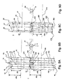
- FIG. 10 a seal of a chimney 29 is shown with respect to the adjoining roof tiles 31 with a sealing strip 111.
- the weather strip 111 is formed in a region 161 flat to the surface of the chimney 29 and connected to the chimney 29.
- the sealing strip 111 is formed on the surface of the roof tiles 31 and forms a sealed transition between the chimney 29 and the roof tiles 31st
- the sealing strip 111 is integrally formed with the roof tiles in a direction perpendicular to the roof ridge.
- a region 181 of the sealing strip 111 is formed exactly perpendicular to the roof tiles.
- the region 191 forms the transition between the regions 171 and 181. It is clear that the sealing material in any directions on surface contours is adaptable, since it can easily bend, stretch and deform in all directions.
- the sealing strip 111 forms a chimney connection element in the embodiment described above.
- the weather strip can also be used on windows, dormers and other transitions to buildings.
- the sealing material can also be used in the connection of pipes.
Landscapes
- Engineering & Computer Science (AREA)
- Mechanical Engineering (AREA)
- Machines For Manufacturing Corrugated Board In Mechanical Paper-Making Processes (AREA)
- Laminated Bodies (AREA)
- Wire Processing (AREA)
Claims (23)
- Procédé pour réaliser un matériau crêpelé (95) avec des plis crêpelés, en particulier un matériau d'étanchéité pour raccords et transitions sur des bâtiments, ledit procédé comportant les étapes :a) mise à disposition d'une bande de matériau (9) déformable avec une direction d'extension principale (90),b1) réalisation d'un profilage longitudinal (91) dans au moins une zone de la bande de matériau (9) déformable, ledit profilage longitudinal étant sensiblement parallèle à la direction d'extension principale (90),
caractérisé par les étapes suivantes :c) réalisation d'un profilage transversal (94) dans au moins une zone de la bande de matériau (9) déformable, ledit profilage transversal (94) étant orienté en formant avec la direction d'extension principale (90) un angle différent de 180°, en particulier un angle sensiblement droit, etd) compression d'au moins un tronçon de la bande de matériau (9) déformable, lequel comporte au moins une zone avec un profilage longitudinal (91) et un profilage transversal (94), de manière à former des plis crêpelés sur la bande de matériau (9). - Procédé selon la revendication 1, caractérisé en ce qu'après l'étape b1) est effectuée une étape b2), au cours de laquelle est effectué le compactage du profilage longitudinal (91).
- Procédé selon la revendication 1 ou 2, caractérisé en ce qu'après l'étape b1) ou b2) est effectuée une étape b3), au cours de laquelle le profilage longitudinal (91) ou le profilage longitudinal compacté (92) est comprimé.
- Procédé selon l'une quelconque des revendications précédentes, caractérisé en ce que, pendant la mise en oeuvre des étapes b1) à d), la bande de matériau (9) est transportée, en particulier en continu, dans le sens de sa direction d'extension principale (90).
- Procédé selon l'une quelconque des revendications précédentes, caractérisé en ce que la réalisation du profilage longitudinal (91) et/ou la réalisation du profilage transversal (94) et/ou le processus de compression sont effectués en continu.
- Procédé selon l'une quelconque des revendications précédentes, caractérisé en ce que pendant la réalisation du profilage longitudinal (91), des ondulations de l'intérieur vers l'extérieur sont appliquées sur la bande de matériau (9) déformable pendant l'étape b1) ou pendant les étapes b1) et b2).
- Procédé selon l'une quelconque des revendications précédentes, caractérisé en ce que pendant la réalisation du profilage longitudinal (91), la bande de matériau (9) déformable est chauffée à une température dans une plage entre 50°C et 200°C, de préférence à une température dans une plage entre 100°C et 150°C.
- Procédé selon l'une quelconque des revendications précédentes, caractérisé en ce que la bande de matériau (9) déformable mise à disposition est une feuille métallique comprenant en particulier de l'aluminium.
- Procédé selon l'une quelconque des revendications précédentes, caractérisé en ce que la bande de matériau (9) déformable mise à disposition est une feuille métallique, doublée d'une feuille plastique et comprenant en particulier de l'aluminium.
- Procédé selon l'une quelconque des revendications précédentes, caractérisé en ce que sous l'effet de la déformation de la bande de matériau (9) au cours des étapes b1) à d), il se forme une réserve de matériau dans la bande de matériau, laquelle permet un redressage de la bande, à la suite duquel la dimension de la bande de matériau dans le sens longitudinal et/ou dans le sens transversal est au moins 30 %, de préférence jusqu'à 80 % supérieure à la dimension dans le sens longitudinal et/ou le sens transversal atteinte par la bande de matériau après l'étape d).
- Ensemble de roues (1) pour la réalisation d'ondulations longitudinales (91) dans une bande de matériau (9) déformable, comprenant une première roue (10) et une deuxième roue (100) ayant chacune un axe de rotation (11, 110),
chaque roue (10, 100) comportant une surface de roulement (16, 160) avec au moins dans certaines zones un profil ondulé, les ondulations du profil ondulé s'étendant le long de la direction circonférentielle de la surface de roulement, et la surface de roulement comprenant une zone médiane (17, 117), adjacente de chaque côté à une zone latérale (18, 180), et
une ligne médiane (12, 120) étant définie, vue radialement à partir de l'axe de rotation (11, 110), par la limite extérieure de la zone médiane (17, 170), et
une ligne latérale (13, 130) étant définie, vue radialement à partir de l'axe de rotation (11, 110), par la limite extérieure des zones latérales (18, 180),
ladite ligne médiane (12, 120) et ladite ligne latérale (13, 130) étant parallèles à l'axe de rotation (11, 110) de la roue (10, 100),
dans la première roue (10), la distance ΔM1 entre la ligne médiane (12) et l'axe de rotation (11) étant supérieure à la distance ΔS1 entre la ligne latérale (13) et l'axe de rotation (11), et dans la deuxième roue (100), la distance ΔM2 entre la ligne médiane (120) et l'axe de rotation (110) étant inférieure à la distance ΔS2 entre la ligne latérale (130) et l'axe de rotation (110),
de telle sorte que la zone médiane (17) de la première roue (10) définit au moins une saillie (14), et la zone médiane (170) de la première roue (100) forme au moins un logement (114) pour la saillie (14) de la première roue (10), lorsque les deux roues (10, 100) roulent, en cours de service, l'une contre l'autre avec leurs surfaces de roulement (16, 160),
caractérisé en ce que
les zones latérales (18) de la première roue (10) comportent un creux d'ondulation (19) et un sommet d'ondulation (15), le creux d'ondulation (19) étant adjacent à la zone médiane (17), et
les zones latérales (180) de la deuxième roue (100) comportent un sommet d'ondulation (119) adjacent à la zone médiane (170),
de telle sorte que le creux d'ondulation (19) dans la zone latérale (18) de la première roue (10) forme un logement pour le sommet d'ondulation (119) dans la zone latérale (180) de la deuxième roue (100),
les zones latérales (180) de la deuxième roue (100) comportant une zone cylindrique (115) qui est adjacente au sommet d'ondulation (119) et dont la surface extérieure est parallèle à l'axe de rotation (110),
de telle sorte que, en cours de service de l'ensemble de roues (1), le sommet d'ondulation (15) dans la zone latérale (18) de la première roue (10) peut rouler sur la zone cylindrique (115) dans la zone latérale (180) de la deuxième roue (100). - Ensemble de roues (1) selon la revendication 11, caractérisé en ce que les sommets d'ondulation (14, 15 ; 119) et les creux d'ondulation (19 ; 114) du profil ondulé ont une section transversale sensiblement semi-circulaire.
- Ensemble de roues (1) selon la revendication 11 ou 12, caractérisé en ce que les sommets d'ondulation (14, 15 ; 119), les creux d'ondulation (19 ; 114) et les zones cylindriques (115) ont sensiblement la même largeur mesurée parallèlement à l'axe de rotation (11, 110) de la roue (10, 100).
- Ensemble de roues (2) pour le compactage d'une bande de matériau (9) munie d'ondulations longitudinales (91), comprenant une première roue (20) et une deuxième roue (200) ayant chacune un axe de rotation (21, 210), chaque roue pouvant être montée rotative et comportant une surface périphérique (27, 270) profilée,
la première roue (20) et la deuxième roue (200) comportant chacune une surface enveloppante (26, 260), qui inclut la surface périphérique (27, 270) profilée et qui est la surface extérieure d'un cylindre autour de l'axe de rotation (21, 210) de la première ou de la deuxième roue (20, 200),
en cours de service de l'ensemble de roues (2), la surface enveloppante (26) de la première roue (20) roulant sur la surface enveloppante (260) de la deuxième roue (200),
les roues (20, 200) comprenant une partie médiane (28, 280) cylindrique par rapport à l'axe de rotation (21, 210), aux deux côtés de laquelle est adjacente respectivement une zone latérale (23, 230) avec une surface orientée en formant avec la face extérieure de la zone médiane cylindrique un angle différent de 180°, en particulier angle de 45°,
les zones latérales (23) d'une roue (20) définissant des saillies par rapport à la zone médiane (28) cylindrique et les zones latérales (230) de l'autre roue (200) étant en retrait vers l'axe de rotation (210) par rapport à la zone médiane (28) cylindrique. - Ensemble de roues (2) selon la revendication 14, caractérisé en ce que la surface d'une zone latérale (23) sur la première roue (20) est parallèle à la surface d'une zone latérale (230) correspondante sur la deuxième roue (200).
- Ensemble de roues (2) selon la revendication 15, caractérisé en ce que la zone médiane (280) d'une roue (200) comporte une zone centrale (281) comprenant un creux (214) pour recevoir au moins une partie d'une ondulation dans la bande de matériau (9) munie d'ondulations longitudinales (91).
- Ensemble de roues (2) selon la revendication 16, caractérisé en ce que le creux (214) possède une section transversale en forme d'arc de cercle, en particulier sensiblement semi-circulaire.
- Ensemble de roues en tandem, comprenant un ensemble de roues (1) selon l'une quelconque des revendications 11 à 13 et un ensemble de roues (2) selon l'une quelconque des revendications 14 à 17, les ensembles de roues (1, 2) étant alignés l'un derrière l'autre par rapport à la direction de transport (90), dans laquelle la bande de matériau (9) déformable défile, en cours de service, à travers l'ensemble de roues en tandem, de telle sorte que, en cours de service, l'ondulation longitudinale (91) formée par l'ensemble de roues (1) défile à travers les surfaces périphériques (27, 270) profilées dans l'ensemble de roues (2).
- Dispositif (101) destiné à être utilisé lors de la fabrication en continu d'un matériau crêpelé, lequel dispositif comprend plusieurs ensembles de roues (1) selon l'une quelconque des revendications 11 à 13, qui sont disposés le long d'une direction de transport (90) d'une bande de matériau (9) déformable défilant en cours de service à travers le dispositif (101).
- Dispositif (202) destiné à être utilisé lors de la fabrication en continu d'un matériau crêpelé, lequel dispositif comprend plusieurs ensembles de roues (2) selon l'une quelconque des revendications 14 à 17, qui sont disposés le long d'une direction de transport (90) d'une bande de matériau (9) déformable défilant en cours de service à travers le dispositif (102).
- Dispositif (102) destiné à être utilisé lors de la fabrication en continu d'un matériau crêpelé, lequel dispositif comprend plusieurs ensembles de roues en tandem selon la revendication 18, qui sont disposés le long d'une direction de transport (90) d'une bande de matériau (9) déformable défilant en cours de service à travers le dispositif (102).
- Dispositif (101, 202, 102) destiné à être utilisé lors de la fabrication en continu d'un matériau crêpelé, selon l'une quelconque des revendications 19 à à 21, caractérisé en ce que les ensembles de roues (1, 2) ou les ensembles de roues en tandem sont disposés sur une ligne qui s'étend en oblique par rapport à la direction de transport (90), et/ou sont disposés les uns par rapport aux autres sensiblement en forme de V et/ou sensiblement en forme de U.
- Dispositif pour la fabrication en continu d'un matériau crêpelé, comprenant un dispositif pour l'acheminement en continu d'une bande de matériau (9) déformable,
au moins un dispositif selon l'une quelconque des revendications 19 à 22 pour la réalisation en continu d'un profilage longitudinal (91, 92) dans la bande de matériau (9) déformable,
un dispositif pour la compression en continu du matériau pour la fabrication d'un matériau avec des ondulations longitudinales (93) comprimées,
un dispositif pour l'évacuation en continu du matériau muni des ondulations longitudinales (93) comprimées.
Priority Applications (4)
| Application Number | Priority Date | Filing Date | Title |
|---|---|---|---|
| AT07001459T ATE548135T1 (de) | 2007-01-24 | 2007-01-24 | Verfahren und vorrichtung zum herstellen eines gekreppten materials für anschlüsse und übergänge an gebäuden |
| PL07001459T PL1949980T3 (pl) | 2007-01-24 | 2007-01-24 | Sposób i urządzenie do wytwarzania fałdowanego materiału do elementów połączeniowych i przejściowych w budynkach |
| EP07001459A EP1949980B1 (fr) | 2007-01-24 | 2007-01-24 | Procédé et dispositif de fabrication d'une bande crêpée pour des éléments de connection et de jonction pour bâtiments |
| US12/014,621 US8647096B2 (en) | 2007-01-24 | 2008-01-15 | Production of a creped material for connections and transitions on buildings |
Applications Claiming Priority (1)
| Application Number | Priority Date | Filing Date | Title |
|---|---|---|---|
| EP07001459A EP1949980B1 (fr) | 2007-01-24 | 2007-01-24 | Procédé et dispositif de fabrication d'une bande crêpée pour des éléments de connection et de jonction pour bâtiments |
Publications (2)
| Publication Number | Publication Date |
|---|---|
| EP1949980A1 EP1949980A1 (fr) | 2008-07-30 |
| EP1949980B1 true EP1949980B1 (fr) | 2012-03-07 |
Family
ID=38268832
Family Applications (1)
| Application Number | Title | Priority Date | Filing Date |
|---|---|---|---|
| EP07001459A Active EP1949980B1 (fr) | 2007-01-24 | 2007-01-24 | Procédé et dispositif de fabrication d'une bande crêpée pour des éléments de connection et de jonction pour bâtiments |
Country Status (4)
| Country | Link |
|---|---|
| US (1) | US8647096B2 (fr) |
| EP (1) | EP1949980B1 (fr) |
| AT (1) | ATE548135T1 (fr) |
| PL (1) | PL1949980T3 (fr) |
Families Citing this family (1)
| Publication number | Priority date | Publication date | Assignee | Title |
|---|---|---|---|---|
| DE102008041832B4 (de) * | 2008-09-05 | 2013-03-21 | Airbus Operations Gmbh | Vorrichtung und Verfahren |
Family Cites Families (3)
| Publication number | Priority date | Publication date | Assignee | Title |
|---|---|---|---|---|
| FI63262C (fi) * | 1980-04-15 | 1983-05-10 | Outokumpu Oy | Foerfarande och anordning foer riktning och foerstyvning av karnplaotar i elektrolytiska raffineringsanlaeggningar |
| SU1222341A1 (ru) * | 1983-08-12 | 1986-04-07 | Днепропетровский Металлургический Институт | Волковый узел прокатного стана |
| US8028557B2 (en) * | 2004-09-08 | 2011-10-04 | The Bradbury Company, Inc. | Methods and apparatus for forming stiffening structures in a strip material |
-
2007
- 2007-01-24 AT AT07001459T patent/ATE548135T1/de active
- 2007-01-24 EP EP07001459A patent/EP1949980B1/fr active Active
- 2007-01-24 PL PL07001459T patent/PL1949980T3/pl unknown
-
2008
- 2008-01-15 US US12/014,621 patent/US8647096B2/en not_active Expired - Fee Related
Also Published As
| Publication number | Publication date |
|---|---|
| US8647096B2 (en) | 2014-02-11 |
| US20080237918A1 (en) | 2008-10-02 |
| EP1949980A1 (fr) | 2008-07-30 |
| ATE548135T1 (de) | 2012-03-15 |
| PL1949980T3 (pl) | 2012-08-31 |
Similar Documents
| Publication | Publication Date | Title |
|---|---|---|
| EP2177702B1 (fr) | Profilé creux, notamment tuyau d'écartement pour un vitrage isolant et dispositif et procédé de fabrication du profilé creux | |
| DE3850364T2 (de) | Wärmerohr und Verfahren zur Herstellung. | |
| DE3785529T2 (de) | Durch kaltlaminierung gebildete strukturen sowie vorrichtung und verfahren zur herstellung derselben. | |
| DE2443691A1 (de) | Gewickeltes doppelwandrohr sowie verfahren und bandmaterial zu seiner herstellung | |
| EP0069401A2 (fr) | Procédé de fabrication d'un matériau composite plant | |
| EP1375023B1 (fr) | Procédé de déformation d'un matériau métallique plat, procédé de production d'un matériau composite ainsi que dispositifs pour l'exécution de ces procédés | |
| EP2212039B1 (fr) | Procédé de fabrication d'un profilé à partir d'un feuillard métallique plat | |
| EP0721537B1 (fr) | Couverture a deformation plastique | |
| EP1949980B1 (fr) | Procédé et dispositif de fabrication d'une bande crêpée pour des éléments de connection et de jonction pour bâtiments | |
| EP4096851A1 (fr) | Ruban métallique utilisé comme armature pour bande de protection de bord et procédé de fabrication de ce ruban métallique | |
| DE60212908T2 (de) | Wellrohr aus schraubenförmig gewickeltem Band | |
| EP0823867B1 (fr) | Procede pour munir un tuyau en plastique d'une gaine metallique | |
| DE102012009845A1 (de) | Rohrstück aus Metallblech und Verfahren zu dessen Herstellung, Streck-Biegevorrichtung zur Herstellung eines Rohrbogens und Verfahren zur Herstellung eines Rohrbogens | |
| EP1793190B1 (fr) | Ailette pour échangeur de chaleur, procédé de fabrication et échangeur de chaleur | |
| EP2667073A1 (fr) | Pièce de tuyau à base de tôles de métal et son procédé de fabrication, dispositif de traction et flexion pour fabrication d'un coude de tube et procédé de fabrication d'un coude de tube | |
| EP1183115B1 (fr) | Materiau de remplissage | |
| EP1039063B1 (fr) | Dispositif et procédé de fabrication d'une bande pour le recouvrement des faîtes et des arêtes de toits, à partir d'une bande en matériau déformable plastiquement | |
| DE3904175A1 (de) | Vorrichtung und verfahren zur feinwellung von blech sowie gewelltes blech | |
| EP1974834A2 (fr) | Raccordement ou bande de finition pour bâtiments à points de flambage | |
| DE10241230B4 (de) | Verfahren und Vorrichtung zum kontinuierlichen Pressen von einem Abschnitt einer profilierten Bahn | |
| DE2438595A1 (de) | Band mit durchbruechen | |
| EP0423073B1 (fr) | Procédé pour courber un stratifié plat | |
| EP1506822A1 (fr) | Procédé et dispositif de fabrication d'un garnissage ordonné | |
| EP1847333A1 (fr) | Méthode de réduction d'épaisseur d'un materiau roulé | |
| EP0890687A2 (fr) | Procédé de fabrication d' un closoir de faitage |
Legal Events
| Date | Code | Title | Description |
|---|---|---|---|
| PUAI | Public reference made under article 153(3) epc to a published international application that has entered the european phase |
Free format text: ORIGINAL CODE: 0009012 |
|
| AK | Designated contracting states |
Kind code of ref document: A1 Designated state(s): AT BE BG CH CY CZ DE DK EE ES FI FR GB GR HU IE IS IT LI LT LU LV MC NL PL PT RO SE SI SK TR |
|
| AX | Request for extension of the european patent |
Extension state: AL BA HR MK RS |
|
| 17P | Request for examination filed |
Effective date: 20090130 |
|
| AKX | Designation fees paid |
Designated state(s): AT BE BG CH CY CZ DE DK EE ES FI FR GB GR HU IE IS IT LI LT LU LV MC NL PL PT RO SE SI SK TR |
|
| GRAP | Despatch of communication of intention to grant a patent |
Free format text: ORIGINAL CODE: EPIDOSNIGR1 |
|
| GRAS | Grant fee paid |
Free format text: ORIGINAL CODE: EPIDOSNIGR3 |
|
| GRAA | (expected) grant |
Free format text: ORIGINAL CODE: 0009210 |
|
| RAP1 | Party data changed (applicant data changed or rights of an application transferred) |
Owner name: EWALD DOERKEN AG |
|
| RIN1 | Information on inventor provided before grant (corrected) |
Inventor name: MEINECKE BERND |
|
| AK | Designated contracting states |
Kind code of ref document: B1 Designated state(s): AT BE BG CH CY CZ DE DK EE ES FI FR GB GR HU IE IS IT LI LT LU LV MC NL PL PT RO SE SI SK TR |
|
| REG | Reference to a national code |
Ref country code: GB Ref legal event code: FG4D Free format text: NOT ENGLISH |
|
| REG | Reference to a national code |
Ref country code: CH Ref legal event code: EP Ref country code: AT Ref legal event code: REF Ref document number: 548135 Country of ref document: AT Kind code of ref document: T Effective date: 20120315 |
|
| REG | Reference to a national code |
Ref country code: IE Ref legal event code: FG4D Free format text: LANGUAGE OF EP DOCUMENT: GERMAN |
|
| REG | Reference to a national code |
Ref country code: DE Ref legal event code: R096 Ref document number: 502007009407 Country of ref document: DE Effective date: 20120503 |
|
| REG | Reference to a national code |
Ref country code: NL Ref legal event code: VDEP Effective date: 20120307 |
|
| PG25 | Lapsed in a contracting state [announced via postgrant information from national office to epo] |
Ref country code: LT Free format text: LAPSE BECAUSE OF FAILURE TO SUBMIT A TRANSLATION OF THE DESCRIPTION OR TO PAY THE FEE WITHIN THE PRESCRIBED TIME-LIMIT Effective date: 20120307 Ref country code: NL Free format text: LAPSE BECAUSE OF FAILURE TO SUBMIT A TRANSLATION OF THE DESCRIPTION OR TO PAY THE FEE WITHIN THE PRESCRIBED TIME-LIMIT Effective date: 20120307 |
|
| LTIE | Lt: invalidation of european patent or patent extension |
Effective date: 20120307 |
|
| PG25 | Lapsed in a contracting state [announced via postgrant information from national office to epo] |
Ref country code: LV Free format text: LAPSE BECAUSE OF FAILURE TO SUBMIT A TRANSLATION OF THE DESCRIPTION OR TO PAY THE FEE WITHIN THE PRESCRIBED TIME-LIMIT Effective date: 20120307 Ref country code: FI Free format text: LAPSE BECAUSE OF FAILURE TO SUBMIT A TRANSLATION OF THE DESCRIPTION OR TO PAY THE FEE WITHIN THE PRESCRIBED TIME-LIMIT Effective date: 20120307 Ref country code: GR Free format text: LAPSE BECAUSE OF FAILURE TO SUBMIT A TRANSLATION OF THE DESCRIPTION OR TO PAY THE FEE WITHIN THE PRESCRIBED TIME-LIMIT Effective date: 20120608 |
|
| REG | Reference to a national code |
Ref country code: PL Ref legal event code: T3 |
|
| PG25 | Lapsed in a contracting state [announced via postgrant information from national office to epo] |
Ref country code: CY Free format text: LAPSE BECAUSE OF FAILURE TO SUBMIT A TRANSLATION OF THE DESCRIPTION OR TO PAY THE FEE WITHIN THE PRESCRIBED TIME-LIMIT Effective date: 20120307 |
|
| PG25 | Lapsed in a contracting state [announced via postgrant information from national office to epo] |
Ref country code: SI Free format text: LAPSE BECAUSE OF FAILURE TO SUBMIT A TRANSLATION OF THE DESCRIPTION OR TO PAY THE FEE WITHIN THE PRESCRIBED TIME-LIMIT Effective date: 20120307 Ref country code: RO Free format text: LAPSE BECAUSE OF FAILURE TO SUBMIT A TRANSLATION OF THE DESCRIPTION OR TO PAY THE FEE WITHIN THE PRESCRIBED TIME-LIMIT Effective date: 20120307 Ref country code: EE Free format text: LAPSE BECAUSE OF FAILURE TO SUBMIT A TRANSLATION OF THE DESCRIPTION OR TO PAY THE FEE WITHIN THE PRESCRIBED TIME-LIMIT Effective date: 20120307 Ref country code: IS Free format text: LAPSE BECAUSE OF FAILURE TO SUBMIT A TRANSLATION OF THE DESCRIPTION OR TO PAY THE FEE WITHIN THE PRESCRIBED TIME-LIMIT Effective date: 20120707 Ref country code: CZ Free format text: LAPSE BECAUSE OF FAILURE TO SUBMIT A TRANSLATION OF THE DESCRIPTION OR TO PAY THE FEE WITHIN THE PRESCRIBED TIME-LIMIT Effective date: 20120307 Ref country code: SE Free format text: LAPSE BECAUSE OF FAILURE TO SUBMIT A TRANSLATION OF THE DESCRIPTION OR TO PAY THE FEE WITHIN THE PRESCRIBED TIME-LIMIT Effective date: 20120307 |
|
| PG25 | Lapsed in a contracting state [announced via postgrant information from national office to epo] |
Ref country code: PT Free format text: LAPSE BECAUSE OF FAILURE TO SUBMIT A TRANSLATION OF THE DESCRIPTION OR TO PAY THE FEE WITHIN THE PRESCRIBED TIME-LIMIT Effective date: 20120709 Ref country code: SK Free format text: LAPSE BECAUSE OF FAILURE TO SUBMIT A TRANSLATION OF THE DESCRIPTION OR TO PAY THE FEE WITHIN THE PRESCRIBED TIME-LIMIT Effective date: 20120307 |
|
| REG | Reference to a national code |
Ref country code: DE Ref legal event code: R082 Ref document number: 502007009407 Country of ref document: DE Representative=s name: VON ROHR PATENTANWAELTE PARTNERSCHAFT, DE Ref country code: DE Ref legal event code: R082 Ref document number: 502007009407 Country of ref document: DE Representative=s name: VON ROHR PATENTANWAELTE PARTNERSCHAFT MBB, DE |
|
| PLBE | No opposition filed within time limit |
Free format text: ORIGINAL CODE: 0009261 |
|
| STAA | Information on the status of an ep patent application or granted ep patent |
Free format text: STATUS: NO OPPOSITION FILED WITHIN TIME LIMIT |
|
| PG25 | Lapsed in a contracting state [announced via postgrant information from national office to epo] |
Ref country code: DK Free format text: LAPSE BECAUSE OF FAILURE TO SUBMIT A TRANSLATION OF THE DESCRIPTION OR TO PAY THE FEE WITHIN THE PRESCRIBED TIME-LIMIT Effective date: 20120307 |
|
| 26N | No opposition filed |
Effective date: 20121210 |
|
| PG25 | Lapsed in a contracting state [announced via postgrant information from national office to epo] |
Ref country code: IT Free format text: LAPSE BECAUSE OF FAILURE TO SUBMIT A TRANSLATION OF THE DESCRIPTION OR TO PAY THE FEE WITHIN THE PRESCRIBED TIME-LIMIT Effective date: 20120307 |
|
| REG | Reference to a national code |
Ref country code: DE Ref legal event code: R097 Ref document number: 502007009407 Country of ref document: DE Effective date: 20121210 |
|
| PG25 | Lapsed in a contracting state [announced via postgrant information from national office to epo] |
Ref country code: ES Free format text: LAPSE BECAUSE OF FAILURE TO SUBMIT A TRANSLATION OF THE DESCRIPTION OR TO PAY THE FEE WITHIN THE PRESCRIBED TIME-LIMIT Effective date: 20120618 |
|
| BERE | Be: lapsed |
Owner name: EWALD DORKEN A.G. Effective date: 20130131 |
|
| PG25 | Lapsed in a contracting state [announced via postgrant information from national office to epo] |
Ref country code: BG Free format text: LAPSE BECAUSE OF FAILURE TO SUBMIT A TRANSLATION OF THE DESCRIPTION OR TO PAY THE FEE WITHIN THE PRESCRIBED TIME-LIMIT Effective date: 20120607 |
|
| PG25 | Lapsed in a contracting state [announced via postgrant information from national office to epo] |
Ref country code: MC Free format text: LAPSE BECAUSE OF NON-PAYMENT OF DUE FEES Effective date: 20130131 |
|
| GBPC | Gb: european patent ceased through non-payment of renewal fee |
Effective date: 20130124 |
|
| REG | Reference to a national code |
Ref country code: IE Ref legal event code: MM4A |
|
| PG25 | Lapsed in a contracting state [announced via postgrant information from national office to epo] |
Ref country code: BE Free format text: LAPSE BECAUSE OF NON-PAYMENT OF DUE FEES Effective date: 20130131 |
|
| PG25 | Lapsed in a contracting state [announced via postgrant information from national office to epo] |
Ref country code: GB Free format text: LAPSE BECAUSE OF NON-PAYMENT OF DUE FEES Effective date: 20130124 |
|
| PG25 | Lapsed in a contracting state [announced via postgrant information from national office to epo] |
Ref country code: IE Free format text: LAPSE BECAUSE OF NON-PAYMENT OF DUE FEES Effective date: 20130124 |
|
| PG25 | Lapsed in a contracting state [announced via postgrant information from national office to epo] |
Ref country code: TR Free format text: LAPSE BECAUSE OF FAILURE TO SUBMIT A TRANSLATION OF THE DESCRIPTION OR TO PAY THE FEE WITHIN THE PRESCRIBED TIME-LIMIT Effective date: 20120307 |
|
| PG25 | Lapsed in a contracting state [announced via postgrant information from national office to epo] |
Ref country code: HU Free format text: LAPSE BECAUSE OF FAILURE TO SUBMIT A TRANSLATION OF THE DESCRIPTION OR TO PAY THE FEE WITHIN THE PRESCRIBED TIME-LIMIT; INVALID AB INITIO Effective date: 20070124 Ref country code: LU Free format text: LAPSE BECAUSE OF NON-PAYMENT OF DUE FEES Effective date: 20130124 |
|
| REG | Reference to a national code |
Ref country code: FR Ref legal event code: PLFP Year of fee payment: 10 |
|
| REG | Reference to a national code |
Ref country code: FR Ref legal event code: PLFP Year of fee payment: 11 |
|
| REG | Reference to a national code |
Ref country code: FR Ref legal event code: PLFP Year of fee payment: 12 |
|
| PGFP | Annual fee paid to national office [announced via postgrant information from national office to epo] |
Ref country code: FR Payment date: 20230124 Year of fee payment: 17 Ref country code: CH Payment date: 20230124 Year of fee payment: 17 Ref country code: AT Payment date: 20230120 Year of fee payment: 17 |
|
| PGFP | Annual fee paid to national office [announced via postgrant information from national office to epo] |
Ref country code: PL Payment date: 20230116 Year of fee payment: 17 Ref country code: DE Payment date: 20230118 Year of fee payment: 17 |
|
| REG | Reference to a national code |
Ref country code: DE Ref legal event code: R119 Ref document number: 502007009407 Country of ref document: DE |
|
| REG | Reference to a national code |
Ref country code: CH Ref legal event code: PL |
|
| REG | Reference to a national code |
Ref country code: AT Ref legal event code: MM01 Ref document number: 548135 Country of ref document: AT Kind code of ref document: T Effective date: 20240124 |
|
| PG25 | Lapsed in a contracting state [announced via postgrant information from national office to epo] |
Ref country code: DE Free format text: LAPSE BECAUSE OF NON-PAYMENT OF DUE FEES Effective date: 20240801 |
|
| PG25 | Lapsed in a contracting state [announced via postgrant information from national office to epo] |
Ref country code: FR Free format text: LAPSE BECAUSE OF NON-PAYMENT OF DUE FEES Effective date: 20240131 |