EP1949977A1 - Distributeur de matériau liquide - Google Patents
Distributeur de matériau liquide Download PDFInfo
- Publication number
- EP1949977A1 EP1949977A1 EP07101208A EP07101208A EP1949977A1 EP 1949977 A1 EP1949977 A1 EP 1949977A1 EP 07101208 A EP07101208 A EP 07101208A EP 07101208 A EP07101208 A EP 07101208A EP 1949977 A1 EP1949977 A1 EP 1949977A1
- Authority
- EP
- European Patent Office
- Prior art keywords
- plunger
- proceeding
- housing
- liquid material
- slot
- Prior art date
- Legal status (The legal status is an assumption and is not a legal conclusion. Google has not performed a legal analysis and makes no representation as to the accuracy of the status listed.)
- Granted
Links
- 239000011344 liquid material Substances 0.000 title claims abstract description 37
- 239000000463 material Substances 0.000 claims abstract description 15
- 239000000758 substrate Substances 0.000 claims abstract description 6
- 238000000034 method Methods 0.000 claims abstract description 4
- 239000012530 fluid Substances 0.000 claims description 18
- 239000004831 Hot glue Substances 0.000 claims description 2
- 238000011144 upstream manufacturing Methods 0.000 claims description 2
- 230000003213 activating effect Effects 0.000 claims 1
- 230000004907 flux Effects 0.000 description 6
- 239000007788 liquid Substances 0.000 description 5
- 239000000853 adhesive Substances 0.000 description 3
- 230000001070 adhesive effect Effects 0.000 description 3
- 238000000354 decomposition reaction Methods 0.000 description 3
- 230000005672 electromagnetic field Effects 0.000 description 2
- 239000012943 hotmelt Substances 0.000 description 2
- 230000003247 decreasing effect Effects 0.000 description 1
- 230000001419 dependent effect Effects 0.000 description 1
- 239000011521 glass Substances 0.000 description 1
- 239000003292 glue Substances 0.000 description 1
- 238000010438 heat treatment Methods 0.000 description 1
- 239000002245 particle Substances 0.000 description 1
- 230000002093 peripheral effect Effects 0.000 description 1
- 239000000565 sealant Substances 0.000 description 1
- 239000007787 solid Substances 0.000 description 1
- 239000001993 wax Substances 0.000 description 1
Images


Classifications
-
- B—PERFORMING OPERATIONS; TRANSPORTING
- B05—SPRAYING OR ATOMISING IN GENERAL; APPLYING FLUENT MATERIALS TO SURFACES, IN GENERAL
- B05C—APPARATUS FOR APPLYING FLUENT MATERIALS TO SURFACES, IN GENERAL
- B05C5/00—Apparatus in which liquid or other fluent material is projected, poured or allowed to flow on to the surface of the work
- B05C5/02—Apparatus in which liquid or other fluent material is projected, poured or allowed to flow on to the surface of the work the liquid or other fluent material being discharged through an outlet orifice by pressure, e.g. from an outlet device in contact or almost in contact, with the work
- B05C5/0225—Apparatus in which liquid or other fluent material is projected, poured or allowed to flow on to the surface of the work the liquid or other fluent material being discharged through an outlet orifice by pressure, e.g. from an outlet device in contact or almost in contact, with the work characterised by flow controlling means, e.g. valves, located proximate the outlet
-
- B—PERFORMING OPERATIONS; TRANSPORTING
- B05—SPRAYING OR ATOMISING IN GENERAL; APPLYING FLUENT MATERIALS TO SURFACES, IN GENERAL
- B05B—SPRAYING APPARATUS; ATOMISING APPARATUS; NOZZLES
- B05B1/00—Nozzles, spray heads or other outlets, with or without auxiliary devices such as valves, heating means
- B05B1/30—Nozzles, spray heads or other outlets, with or without auxiliary devices such as valves, heating means designed to control volume of flow, e.g. with adjustable passages
- B05B1/3033—Nozzles, spray heads or other outlets, with or without auxiliary devices such as valves, heating means designed to control volume of flow, e.g. with adjustable passages the control being effected by relative coaxial longitudinal movement of the controlling element and the spray head
- B05B1/304—Nozzles, spray heads or other outlets, with or without auxiliary devices such as valves, heating means designed to control volume of flow, e.g. with adjustable passages the control being effected by relative coaxial longitudinal movement of the controlling element and the spray head the controlling element being a lift valve
- B05B1/3046—Nozzles, spray heads or other outlets, with or without auxiliary devices such as valves, heating means designed to control volume of flow, e.g. with adjustable passages the control being effected by relative coaxial longitudinal movement of the controlling element and the spray head the controlling element being a lift valve the valve element, e.g. a needle, co-operating with a valve seat located downstream of the valve element and its actuating means, generally in the proximity of the outlet orifice
- B05B1/3053—Nozzles, spray heads or other outlets, with or without auxiliary devices such as valves, heating means designed to control volume of flow, e.g. with adjustable passages the control being effected by relative coaxial longitudinal movement of the controlling element and the spray head the controlling element being a lift valve the valve element, e.g. a needle, co-operating with a valve seat located downstream of the valve element and its actuating means, generally in the proximity of the outlet orifice the actuating means being a solenoid
Definitions
- the present invention relates to an Apparatus for dispensing liquid material to a substrate
- a housing having a bore and an inlet for supplying liquid material from a material source to the bore, a nozzle communicating with the inlet, the nozzle having a discharge opening for dispensing the liquid material, a movable plunger mounted for reciprocal movement between a closed and an open position, wherein in the open position, liquid material is dispensed from the discharge opening and in the closed position, liquid material is prevented from being dispensed from the discharge opening, and actuation means for moving the plunger between the closed and the open position.
- Fluid dispensers of this type are used to dispense fluid materials such as adhesives, sealants, hotmelt adhesive and the like. More specifically, this invention is directed to electromagnetically actuated dispensing apparatus, also known as electric guns.
- an electric gun comprises an magnetic pole piece, a magnetic plunger or armature, a valve stem coupled for movement with the armature and an electromagnetic coil which is part of the actuation means for moving the plunger.
- the armature can be moved relative to the pole piece by selectively energizing and de-energizing the electromagnetic coil. The movement of the plunger or armature towards the pole piece disengages the valve stem from a valve seat and opens the dispensing module.
- a biasing means preferably a return spring forces the armature away from the pole piece.
- the valve stem is urged into contact with the valve seat, to close the module.
- modules are known from US 6,994,234 or EP 0 908 240 , owned by the present applicant.
- the frequency of the reciprocating movement of the plunger is referred to as cycle rate.
- the cycle rate has an influence on the shape of the material dispensed on a substrate.
- at least one flux guide element is conventionally employed in order to strengthen the magnetic field by improving the magnetic flux.
- These flux guide elements can be tubular structures surrounding the plunger, the electromagnetic coil and/or the pole piece and can be formed of the housing.
- eddy currents can be generated within the flux guide elements, which can decrease the cycle rate. Circumferential electrical currents retard the dissipation of the magnetic field.
- US 6,994,234 suggests a gap in a flux guide element which is formed by the housing.
- the dispensing apparatus includes a plunger which has at least one slot essentially extending from the outer periphery to essentially the centre of the plunger.
- the slot or gap within the plunger further improves the performance characteristics such as the cycle rate by avoiding eddy currents within the plunger.
- the slot extends essentially from outer periphery to an inner portion of the plunger.
- the slot may extend to essentially the center of the plunger or to an inner bore within the plunger. The slot or gap thus results in an interruption of eddy currents within the plunger, so that upon de-energisation of the actuation means the plunger is moved faster into the closed position.
- the invention solves the object with an apparatus having the features of claim 2.
- the pole piece comprises at least one slot which essentially extends from the outer periphery to essentially the center of the pole piece.
- a slot which extends from the outer peripheral surface substantially towards the center of the pole piece further improves the performance characteristics such as the cycle rate of the apparatus.
- the reason for this improvement is essentially the same as explained above with reference to a slotted plunger or armature.
- the magnetic fields within the flux guiding elements can be reduced quicker by substantially avoiding eddy currents which would occur during the de-energisation of the coil.
- the cycle rates are optimized if both, the plunger and pole piece, comprise at least one slot for reducing eddy currents.
- the module is improved if, the housing has at least one slot essentially extending from the outer periphery to essentially the centre of the housing.
- the slot for reducing eddy currents is particularly effective if it extends over the entire length of the pole piece and/or the plunger and/or the housing, respectively.
- the slots of the plunger, the housing and the pole piece are axially aligned.
- the plunger has a stepped diameter defining a first portion of a first diameter and a first end surface , a second portion of a reduced diameter and that the slot extends essentially along the first and second portion.
- the plunger has a third portion with further reduced diameter, the first and the second portion containing a concentrically bore and at least one angled flow channel intersecting with bore.
- the fluid dynamics within the apparatus are further substantially improved in this way, since fluid material can flow within the bores and flow channels during the movement of the plunger.
- the characteristics are further improved if the plunger includes at least one groove on the outer surface of the first portion of the plunger. Such groove only has a relatively small depth such that it is not effective for reducing eddy currents and only is effective with regards to the liquid flow characteristics and an improved plunger movement.
- the plunger comprises means for generating a magnetic field for the selected movement of the plunger.
- the biasing means can be formed by a spring which biases the plunger into the closed position and the valve stem into contact with the valve seat.
- a sleeve member is provided within the housing and effective for guiding the moveable plunger to perform a linear reciprocating movement.
- the sleeve member is attached to a first manifold which is attached to an upper end of the housing and has an inlet for supplying liquid material into the housing.
- the sleeve member may comprise a slot extending in axial direction. This slot further improves the cycle rate. Further improvements and preferred embodiments are subject of the dependent claims.
- the method and apparatus of this invention is described in connection with dispensing liquid material.
- Such materials include hot melt polymeric materials used in adhesive applications. Hot melt materials are usually solid at room temperature but convert into a liquid state when heated. state. It should be understood that the methods and apparatus of this invention are believed to be equally applicable for use in connection with the dispensing of other heated fluid materials, such as waxes, as well as those adhesives which are normally a liquid at room or ambient temperature and therefore do not require heating and are sometimes referred to as cold glue.
- FIG. 1 the essential parts of the apparatus for dispensing liquid material are shown.
- Housing 10 forms the central part of the apparatus.
- a first manifold 17 is arranged adjacent to the housing 10 in upstream direction of the flow and contains inlet 18 which is connectable to a material source (not shown) for the supply of liquid material.
- a second manifold 22 follows the housing 10.
- the lower manifold 22 comprises means for receiving nozzle 24 in which discharge opening 26 is integrated.
- the plunger 28 and pole piece 56 can be inserted into the first and second manifolds 17, 22 as well as into the housing 10.
- the plunger 28 is provided with spring 62 for biasing the plunger 28 into a position in which the flow of the liquid material is interrupted.
- the pole piece 56 comprises slot 72
- the housing 10 comprises slot 68
- the plunger 28 comprises slot 46. All the slots are axially aligned to each other. However, different alignments are also possible and within the scope of this invention.
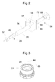
- the first manifold 17 is shown in an enlarged exploded view together with the plunger 28 and the pole piece 56.
- the first manifold 17 comprises sleeve member 20 into which the plunger 28 as well as the pole piece 56 are introducible guiding the plunger 28 and the pole piece 56.
- the plunger 28 is mounted for the reciprocal movement.
- the pole piece 56 comprises an end surface 90, a recess 88 and a bore 58 which intersects with the slot 72. Via the recess 88, the bore 58 is in fluid communication with the inlet 18.
- the sleeve member 20 further comprises a slot 74 on its outer surface extending through its entire wall.
- the slot 74 only partially extends in axial direction over the length of the sleeve member 20. However, other extensions of the slot 74 are also possible.
- the slot 74 is axially aligned with the slot 46 of the plunger 20, the slot 68 of the housing 10 and slot 72 of the pole piece 56.
- nozzle 24 contains means for being received by the second manifold 22, e.g. threats. Furthermore, the nozzle comprises a flow chamber 44 in which protrusions 52 of the plunger 28 can be inserted. In downstream direction, the flow channel enters into valve seat 86. It essentially consists of a conically tapering section within the nozzle. Further, the nozzle 24 forms the discharge opening 26 through which the liquid material leaves the apparatus and can be applied to a substrate.
- the plunger 28 is subdivided into three portions 32, 34 and 36 and has an end surface 33 which contains crank 70.
- the three portions 32, 34 and 36 have different diameters.
- the first portion 32 has the biggest, the second portion 34 a reduced diameter relative to the first portion, and the third portion 36 an further reduced diameter.
- the diameter of the first portion closely approximates that of the inner diameter of the sleeve member 20. This helps to keep the plunger 28 properly aligned as it slides back and forth. While a close fit provides for good guiding of the plunger 28, it does not provide a good flow path for the material.
- grooves 50 extend axially along the outer periphery. Causing the fluid to flow past the plunger in this manner helps to prevent dead spots from occurring in the flow of the liquid material through the dispenser, as well as helping to reduce the force required to move the plunger 28 back and forth. With dead spots, the liquid material may begin to oxidize to produce undesirable particles or chunks, commonly known as char.
- the grooves 50 have a semicircular cross-section. Having a semi-circular cross-section provides for better magnetic efficiency and improved fluid flow over a straight sided slot. It is understood that the grooves 50 can have different arrangements and cross sections being within the scope of this invention.
- a concentrical bore 38 extends through the first and second portion 32, 34.
- the plunger 28 comprises at least one angled flow channel 40 which intersects with the bore 38.
- the slot 46 extents over the entire length of the bore 38, spreading over the first and second portion 32, 34 of the plunger 28.
- the protrusions 52 contain at least one through hole 80 arranged in axial direction.
- the protrusions 52 for receiving the biasing means such as the spring 62 are arranged on the third portion 36 of the plunger 28.
- the spring 62 provides a biasing force for urging the ball 84 into engagement with the seat 86 to prevent the flow of material from the discharge outlet 26.
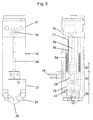
- Fig. 5 shows the apparatus in its mounted configuration.
- electrical coils 54 are arranged which can be energised via a power supply 78.
- the pole piece 56 is introduced into the sleeve member 20 of the first manifold 17 (see Fig. 2 ) and tightly connected by appropriate means (not shown). Subsequently, the first manifold 17 is introduced into the housing 10, the latter carrying the coils 54. The spring 62 is put over the plunger 28 such that it abuts against the protrusions 52. The plunger is pushed into the sleeve member 20 until the spring 62 abuts against the housing 10. The nozzle is attached to the lower manifold 22. The first manifold 17, the housing 10 and the second manifold 22 are now attached to each other, e.g. by screws (not shown).
- the flow path of the liquid material is as follows: The liquid material enters into the apparatus via the inlet 18 and further continues into the recess 88 of the pole piece 56 ( Fig. 2 ). The recess 88 is in fluid communication with the bore 58 and the slot 72 of the pole piece 56. Accordingly, the liquid material is further directed through the pole piece 56 until it reaches the lower end surface 90.
- the generated magnetic field will induce an electromagnetic field which will cause the plunger 28 to be attracted to pole piece 56.
- This force will be sufficient to overcome the force of the spring 62 thereby drawing the end surface 33 of the plunger 28 towards the lower end surface 90 of pole piece 56.
- This in turn causes the ball 84 to be spaced from the valve seat 86 thereby causing a fluid flow from the fluid chamber 44 to the discharge opening 26. This allows the liquid material to be dispensed from the discharge opening 26.
- the coil is de-energised, the field collapses and the plunger 28 will be moved back to the closed position by the spring 62.
- the reciprocal movement of the plunger 28 has to be conducted as quickly as possible. This requires that the electromagnetic field is generated but also decomposed as quickly as possible.
- the decomposition of the magnetic field has been found to be the limiting step in realising dispensing cycles of short intervals.
- the end surface 33 of the first portion 32 of the plunger 28 When dispensing, the end surface 33 of the first portion 32 of the plunger 28 will be adjacent to and/or in contact with the end surface 90 of the pole piece 56. Liquid material trapped between the end surface 33 of the plunger 28 and the end surface 90 of the pole piece 56 will contribute to an increase in the force required to begin to move the plunger 28 to the closed position and/or will cause the closing response time to increase. This phenomenon is similar to the increase in force that is required to separate two pieces of glass which have a drop of fluid placed in between them.
- the crank 70 on the end surface 33 of the plunger 28 serves to reduce the contact area between the end surface 33 and the end surface 90 of the pole piece 56 such that the force required to move the plunger 28 to the closed position is reduced. At the same time, the closing response time of the plunger upon decomposition of the magnetic field will decrease.
Priority Applications (4)
| Application Number | Priority Date | Filing Date | Title |
|---|---|---|---|
| ES07101208T ES2366657T3 (es) | 2007-01-25 | 2007-01-25 | Aparato para dispensar material líquido. |
| EP07101208A EP1949977B1 (fr) | 2007-01-25 | 2007-01-25 | Distributeur de matériau liquide |
| US11/965,328 US8070077B2 (en) | 2007-01-25 | 2007-12-27 | Apparatus for dispensing liquid material |
| CN200810008843.0A CN101229533B (zh) | 2007-01-25 | 2008-01-25 | 用于分配液体材料的设备 |
Applications Claiming Priority (1)
| Application Number | Priority Date | Filing Date | Title |
|---|---|---|---|
| EP07101208A EP1949977B1 (fr) | 2007-01-25 | 2007-01-25 | Distributeur de matériau liquide |
Publications (2)
| Publication Number | Publication Date |
|---|---|
| EP1949977A1 true EP1949977A1 (fr) | 2008-07-30 |
| EP1949977B1 EP1949977B1 (fr) | 2011-08-10 |
Family
ID=38190890
Family Applications (1)
| Application Number | Title | Priority Date | Filing Date |
|---|---|---|---|
| EP07101208A Active EP1949977B1 (fr) | 2007-01-25 | 2007-01-25 | Distributeur de matériau liquide |
Country Status (4)
| Country | Link |
|---|---|
| US (1) | US8070077B2 (fr) |
| EP (1) | EP1949977B1 (fr) |
| CN (1) | CN101229533B (fr) |
| ES (1) | ES2366657T3 (fr) |
Cited By (1)
| Publication number | Priority date | Publication date | Assignee | Title |
|---|---|---|---|---|
| CN109290134A (zh) * | 2018-11-26 | 2019-02-01 | 深圳市博锐自动化设备有限公司 | 一种顶针式点胶阀 |
Families Citing this family (4)
| Publication number | Priority date | Publication date | Assignee | Title |
|---|---|---|---|---|
| MY191954A (en) * | 2011-03-28 | 2022-07-20 | Fishman Corp | System and method for releasably coupling a fluid dispenser to a dispensing system |
| EP2771128A4 (fr) * | 2011-10-28 | 2015-09-30 | Hewlett Packard Development Co | Procédé d'adressage parallèle |
| CN103586163B (zh) * | 2013-11-20 | 2016-08-17 | 东北石油大学 | 交直流两用小型自动涂胶机 |
| EP3702047A1 (fr) | 2019-03-01 | 2020-09-02 | Nordson Corporation | Appareil de distribution de matériau liquide sur un substrat |
Citations (9)
| Publication number | Priority date | Publication date | Assignee | Title |
|---|---|---|---|---|
| US3043336A (en) * | 1959-04-17 | 1962-07-10 | Atkomatic Valve Company Inc | Solenoid valve |
| FR2498002A1 (fr) * | 1981-01-09 | 1982-07-16 | Shoketsu Kinzoku Kogyo Kk | Actionneur a electro-aimant |
| DE3841474A1 (de) * | 1988-12-09 | 1990-06-13 | Macon Gmbh Klebstoff Auftragsg | Ventil zur zeitgesteuerten abgabe von fluessigem bis gelartigem medium |
| US4962871A (en) * | 1989-07-24 | 1990-10-16 | Valco Cincinnati, Inc. | Applicator utilizing high speed non-contact extrusion valve |
| EP0711943A2 (fr) * | 1994-10-31 | 1996-05-15 | Nordson Corporation | Distributeur de matières chaudes liquides |
| EP0908240A2 (fr) * | 1997-10-10 | 1999-04-14 | Nordson Corporation | Appareil pour délivrer un adhésif |
| WO1999060262A1 (fr) * | 1998-05-15 | 1999-11-25 | Siemens Automotive Corporation | Boitier a encoches pour injecteur |
| EP1123752A2 (fr) * | 2000-02-11 | 2001-08-16 | TLX Technologies | Valve pour applicateur de fluides visqueux |
| US20040195278A1 (en) * | 2003-04-03 | 2004-10-07 | Nordson Corporation | Electrically-operated dispensing module |
Family Cites Families (3)
| Publication number | Priority date | Publication date | Assignee | Title |
|---|---|---|---|---|
| US6481596B1 (en) * | 2001-07-12 | 2002-11-19 | Ideal Instruments, Inc. | Metering device |
| US6669057B2 (en) * | 2001-10-31 | 2003-12-30 | Nordson Corporation | High-speed liquid dispensing modules |
| US6916023B2 (en) * | 2002-08-30 | 2005-07-12 | Illinois Tool Works Inc. | Self-adjusting cartridge seal |
-
2007
- 2007-01-25 ES ES07101208T patent/ES2366657T3/es active Active
- 2007-01-25 EP EP07101208A patent/EP1949977B1/fr active Active
- 2007-12-27 US US11/965,328 patent/US8070077B2/en active Active
-
2008
- 2008-01-25 CN CN200810008843.0A patent/CN101229533B/zh not_active Expired - Fee Related
Patent Citations (9)
| Publication number | Priority date | Publication date | Assignee | Title |
|---|---|---|---|---|
| US3043336A (en) * | 1959-04-17 | 1962-07-10 | Atkomatic Valve Company Inc | Solenoid valve |
| FR2498002A1 (fr) * | 1981-01-09 | 1982-07-16 | Shoketsu Kinzoku Kogyo Kk | Actionneur a electro-aimant |
| DE3841474A1 (de) * | 1988-12-09 | 1990-06-13 | Macon Gmbh Klebstoff Auftragsg | Ventil zur zeitgesteuerten abgabe von fluessigem bis gelartigem medium |
| US4962871A (en) * | 1989-07-24 | 1990-10-16 | Valco Cincinnati, Inc. | Applicator utilizing high speed non-contact extrusion valve |
| EP0711943A2 (fr) * | 1994-10-31 | 1996-05-15 | Nordson Corporation | Distributeur de matières chaudes liquides |
| EP0908240A2 (fr) * | 1997-10-10 | 1999-04-14 | Nordson Corporation | Appareil pour délivrer un adhésif |
| WO1999060262A1 (fr) * | 1998-05-15 | 1999-11-25 | Siemens Automotive Corporation | Boitier a encoches pour injecteur |
| EP1123752A2 (fr) * | 2000-02-11 | 2001-08-16 | TLX Technologies | Valve pour applicateur de fluides visqueux |
| US20040195278A1 (en) * | 2003-04-03 | 2004-10-07 | Nordson Corporation | Electrically-operated dispensing module |
Cited By (2)
| Publication number | Priority date | Publication date | Assignee | Title |
|---|---|---|---|---|
| CN109290134A (zh) * | 2018-11-26 | 2019-02-01 | 深圳市博锐自动化设备有限公司 | 一种顶针式点胶阀 |
| CN109290134B (zh) * | 2018-11-26 | 2023-12-01 | 深圳市博锐自动化设备有限公司 | 一种顶针式点胶阀 |
Also Published As
| Publication number | Publication date |
|---|---|
| US8070077B2 (en) | 2011-12-06 |
| CN101229533A (zh) | 2008-07-30 |
| CN101229533B (zh) | 2012-12-26 |
| EP1949977B1 (fr) | 2011-08-10 |
| US20080179352A1 (en) | 2008-07-31 |
| ES2366657T3 (es) | 2011-10-24 |
Similar Documents
| Publication | Publication Date | Title |
|---|---|---|
| JP4372865B2 (ja) | 接着材吐出装置及び液体材料を吐出する方法 | |
| EP1949977B1 (fr) | Distributeur de matériau liquide | |
| US6305583B1 (en) | Valve for viscous fluid applicator | |
| US5405050A (en) | Electric dispenser | |
| EP2774157B1 (fr) | Solénoïde doté d'un composant surmoulé | |
| EP2018910B1 (fr) | Ensemble formant vanne de distribution de colle thermofusible actionné par deux aimants alignés | |
| EP2852753B1 (fr) | Boîtier de soupape destiné à une soupape d'injection et soupape d'injection | |
| KR20060050285A (ko) | 전자기 작동식 밸브용의 신속 응답형 솔레노이드 | |
| US20210278007A1 (en) | Solenoid | |
| US20130020414A1 (en) | Spray gun nozzle tip with integrated seal and auto aligining fluid path | |
| US9146562B2 (en) | Adjustable doser valve | |
| WO2015041922A1 (fr) | Distributeur de fluide utilisant deux bobines, et procédés de distribution de fluide | |
| US7806140B2 (en) | Power saving locking coil | |
| EP1169135B1 (fr) | Procede de distribution de liquide visqueux | |
| EP3702047A1 (fr) | Appareil de distribution de matériau liquide sur un substrat | |
| JPH1151234A (ja) | 三方弁及びその製造方法 |
Legal Events
| Date | Code | Title | Description |
|---|---|---|---|
| PUAI | Public reference made under article 153(3) epc to a published international application that has entered the european phase |
Free format text: ORIGINAL CODE: 0009012 |
|
| AK | Designated contracting states |
Kind code of ref document: A1 Designated state(s): AT BE BG CH CY CZ DE DK EE ES FI FR GB GR HU IE IS IT LI LT LU LV MC NL PL PT RO SE SI SK TR |
|
| AX | Request for extension of the european patent |
Extension state: AL BA HR MK RS |
|
| 17P | Request for examination filed |
Effective date: 20090113 |
|
| AKX | Designation fees paid |
Designated state(s): DE ES IT |
|
| 17Q | First examination report despatched |
Effective date: 20090409 |
|
| GRAP | Despatch of communication of intention to grant a patent |
Free format text: ORIGINAL CODE: EPIDOSNIGR1 |
|
| GRAS | Grant fee paid |
Free format text: ORIGINAL CODE: EPIDOSNIGR3 |
|
| GRAA | (expected) grant |
Free format text: ORIGINAL CODE: 0009210 |
|
| AK | Designated contracting states |
Kind code of ref document: B1 Designated state(s): DE ES IT |
|
| REG | Reference to a national code |
Ref country code: DE Ref legal event code: R096 Ref document number: 602007016369 Country of ref document: DE Effective date: 20111020 |
|
| REG | Reference to a national code |
Ref country code: ES Ref legal event code: FG2A Ref document number: 2366657 Country of ref document: ES Kind code of ref document: T3 Effective date: 20111024 |
|
| PLBE | No opposition filed within time limit |
Free format text: ORIGINAL CODE: 0009261 |
|
| STAA | Information on the status of an ep patent application or granted ep patent |
Free format text: STATUS: NO OPPOSITION FILED WITHIN TIME LIMIT |
|
| 26N | No opposition filed |
Effective date: 20120511 |
|
| REG | Reference to a national code |
Ref country code: DE Ref legal event code: R097 Ref document number: 602007016369 Country of ref document: DE Effective date: 20120511 |
|
| PG25 | Lapsed in a contracting state [announced via postgrant information from national office to epo] |
Ref country code: IT Free format text: LAPSE BECAUSE OF NON-PAYMENT OF DUE FEES Effective date: 20120125 |
|
| PGFP | Annual fee paid to national office [announced via postgrant information from national office to epo] |
Ref country code: ES Payment date: 20150128 Year of fee payment: 9 |
|
| PG25 | Lapsed in a contracting state [announced via postgrant information from national office to epo] |
Ref country code: ES Free format text: LAPSE BECAUSE OF NON-PAYMENT OF DUE FEES Effective date: 20160126 |
|
| REG | Reference to a national code |
Ref country code: ES Ref legal event code: FD2A Effective date: 20180625 |
|
| P01 | Opt-out of the competence of the unified patent court (upc) registered |
Effective date: 20230526 |
|
| PGFP | Annual fee paid to national office [announced via postgrant information from national office to epo] |
Ref country code: DE Payment date: 20240119 Year of fee payment: 18 |