EP1949865A1 - Flexible shaft bone reduction tool - Google Patents
Flexible shaft bone reduction tool Download PDFInfo
- Publication number
- EP1949865A1 EP1949865A1 EP08250204A EP08250204A EP1949865A1 EP 1949865 A1 EP1949865 A1 EP 1949865A1 EP 08250204 A EP08250204 A EP 08250204A EP 08250204 A EP08250204 A EP 08250204A EP 1949865 A1 EP1949865 A1 EP 1949865A1
- Authority
- EP
- European Patent Office
- Prior art keywords
- rigid
- end portion
- bone
- reduction tool
- flexible
- Prior art date
- Legal status (The legal status is an assumption and is not a legal conclusion. Google has not performed a legal analysis and makes no representation as to the accuracy of the status listed.)
- Granted
Links
- 210000000988 bone and bone Anatomy 0.000 title claims abstract description 91
- 238000003780 insertion Methods 0.000 claims abstract description 3
- 230000037431 insertion Effects 0.000 claims abstract description 3
- 239000012634 fragment Substances 0.000 description 30
- 210000000689 upper leg Anatomy 0.000 description 20
- 238000000034 method Methods 0.000 description 8
- 210000004872 soft tissue Anatomy 0.000 description 6
- 230000035876 healing Effects 0.000 description 2
- 238000002601 radiography Methods 0.000 description 2
- 238000013459 approach Methods 0.000 description 1
- 230000007423 decrease Effects 0.000 description 1
- 230000003247 decreasing effect Effects 0.000 description 1
- 238000010586 diagram Methods 0.000 description 1
- 210000001981 hip bone Anatomy 0.000 description 1
- 210000002414 leg Anatomy 0.000 description 1
- 239000000463 material Substances 0.000 description 1
- 239000012858 resilient material Substances 0.000 description 1
- 210000001519 tissue Anatomy 0.000 description 1
Images


Classifications
-
- A—HUMAN NECESSITIES
- A61—MEDICAL OR VETERINARY SCIENCE; HYGIENE
- A61B—DIAGNOSIS; SURGERY; IDENTIFICATION
- A61B17/00—Surgical instruments, devices or methods
- A61B17/56—Surgical instruments or methods for treatment of bones or joints; Devices specially adapted therefor
- A61B17/58—Surgical instruments or methods for treatment of bones or joints; Devices specially adapted therefor for osteosynthesis, e.g. bone plates, screws or setting implements
- A61B17/68—Internal fixation devices, including fasteners and spinal fixators, even if a part thereof projects from the skin
- A61B17/72—Intramedullary devices, e.g. pins or nails
- A61B17/7208—Flexible pins, e.g. ENDER pins
-
- A—HUMAN NECESSITIES
- A61—MEDICAL OR VETERINARY SCIENCE; HYGIENE
- A61B—DIAGNOSIS; SURGERY; IDENTIFICATION
- A61B17/00—Surgical instruments, devices or methods
- A61B17/56—Surgical instruments or methods for treatment of bones or joints; Devices specially adapted therefor
- A61B17/58—Surgical instruments or methods for treatment of bones or joints; Devices specially adapted therefor for osteosynthesis, e.g. bone plates, screws or setting implements
- A61B17/88—Osteosynthesis instruments; Methods or means for implanting or extracting internal or external fixation devices
- A61B17/8897—Guide wires or guide pins
-
- A—HUMAN NECESSITIES
- A61—MEDICAL OR VETERINARY SCIENCE; HYGIENE
- A61B—DIAGNOSIS; SURGERY; IDENTIFICATION
- A61B17/00—Surgical instruments, devices or methods
- A61B17/56—Surgical instruments or methods for treatment of bones or joints; Devices specially adapted therefor
- A61B17/58—Surgical instruments or methods for treatment of bones or joints; Devices specially adapted therefor for osteosynthesis, e.g. bone plates, screws or setting implements
- A61B17/88—Osteosynthesis instruments; Methods or means for implanting or extracting internal or external fixation devices
- A61B17/92—Impactors or extractors, e.g. for removing intramedullary devices
- A61B17/921—Impactors or extractors, e.g. for removing intramedullary devices for intramedullary devices
-
- A—HUMAN NECESSITIES
- A61—MEDICAL OR VETERINARY SCIENCE; HYGIENE
- A61B—DIAGNOSIS; SURGERY; IDENTIFICATION
- A61B17/00—Surgical instruments, devices or methods
- A61B2017/0046—Surgical instruments, devices or methods with a releasable handle; with handle and operating part separable
Definitions
- This invention relates to the field of orthopaedics and more particularly to tools for setting fractures.
- Fractures of long bones such as the femur are fairly common.
- Various techniques are employed for holding together parts of a fractured bone during the healing process.
- the fracture Prior to the fixation of the bone fragments, however, it is first required that the fracture be reduced, that is, the various bone fragments or pieces must be repositioned in their proper relative arrangement before the fractured bone can be fixed or stabilized for healing.
- a great many devices have been proposed for the reduction of fractures of this type. While many of these devices have found application and have advantages relative one to another, there remain some problems and areas of continuing concern.
- fixation pins are inserted through the bone fragments to provide for the desired reduction.
- this device is said to be able to reduce the fracture, it involves a relatively complicated procedure in that movement of one component will affect the orientation of any other component. Furthermore, rotation is limited in view of the skin and tissue through which the pins penetrate.
- Elastic nails have also been used to provide reduction.
- the nails are passed into the intramedullary canal of a bone through a hole in the bone and are then rotated so as to reduce the fractured femoral head using the entry point into the intramedullary canal as a fulcrum. Since the bone hole serves as a fulcrum point, elastic nails are not generally capable of fine adjustment or ease of use within the intramedullary canal. Moreover, because the entire length of the nails is elastic, fine control over the positioning of the distal end of the nail is difficult.
- the invention provides a bone reduction tool comprising a shaft including a proximal end portion, a distal end portion for insertion into a fractured bone, a first rigid portion located at the distal end portion, and a first flexible portion located between the first rigid portion and the proximal end portion.
- the invention provides a bone reduction tool comprising:
- Apparatus provided by the present invention can be used in a method of reducing a fractured bone comprising:
- the apparatus which is provided by the invention can provide improved reduction capabilities, and can help to minimise damage to soft tissue while allowing reduction of bone fragments which are misaligned.
- FIG. 1 shows a bone reduction tool 100.
- the tool 100 includes an elongated, generally cylindrical shaft 102 with a proximal end portion 104 and a distal end portion 106.
- a T-shaped handle 108 is attached to the proximal end portion 104.
- the shaft 102 has an internal bore 110 extending completely along the longitudinal axis of the tool 100 from the T-shaped handle 108 to the distal end portion 106 which can be seen in FIG. 2 .
- the distal end portion 106 is hook shaped when viewed from the side as best seen in FIG. 3 .
- Two flexible shaft portions 112 and 114 separate a medial shaft portion 116 from the distal end portion 106 and the proximal end portion 104, respectively.
- the flexible shaft portions 112 and 114 in this embodiment include slits 118 and 120.
- the slits 118 and 120 extend in a generally helical fashion along the longitudinal axis of the tool 100. Details of the slits 118 and 120, which in this embodiment are similar, are explained with reference to FIG. 4 .
- the slit 120 extends from the outer surface 122 of the shaft 102 to the bore 110.
- the slit 120 is in the form of a continuous chain of alternating partial links such as partial links 124 and 126.
- Each end of the slit 120 includes a bore such as bore 128.
- the bore 128 alleviates stress at the end of the slit 120 as the tool flexes as discussed below.
- the entire shaft 102 in this embodiment is made from a resilient material. Accordingly, the slits 118 and 120 effectively weaken the structure of the shaft 102. Consequently, while the alternating partial link structure provides sufficient strength and rigidity for the shaft 102, the slits 118 and 120 allow the flexible shaft portions 112 and 114, respectively, to be more flexible than the more rigid proximal end portion 104, distal end portion 106 and medial shaft portion 116. Since the slit 120 extends along the shaft 102 for a greater distance than the slit 118, the flexible shaft portion 114 is more weakened than the flexible shaft portion 112, and thus more easily flexed. The same result may be effected by modifying the relative width of the slits or the pitch of the slits since a given area will become more flexible as the amount of material within the area is decreased.
- the width of the slit 120, along with the orientation and pattern of the slit 120, can be modified to allow for greater or lesser extents of flex.
- the relative locations of the flexible shaft portions 112 and 114, along with the relative flexibility of the flexible shaft portions 112 and 114, are selected to provide the desired amount of fine control at the distal end portion 106 while allowing the handle 108 to be positioned to allow entry of the tool 100 into a bone while minimizing the impingement of the tool 102 on soft tissues proximate to the bone. This is further described with reference to FIGs. 7 to 11 which illustrate a method of reducing a fracture.
- a partial schematic representation of the thigh area 132 of a patient is shown including a hip bone 134 and thigh (femur) bone 136.
- the femur 136 is fractured into a proximal bone fragment 138 and a medial bone fragment 140 at the fractured ends 142 and 144.
- the femur 136 is further fractured into a distal bone fragment 146 at the fractured ends 148 and 150.
- the thigh 132 is placed into traction in accordance with an appropriate procedure. This causes the fractured end 142 of the medial bone fragment 140 to be positioned leftwardly of the fractured end 144 of the proximal bone fragment 138 as viewed in FIG. 7 .
- the fractured end 148 of the distal bone fragment 146 is positioned leftwardly of the fractured end 150 of the medial bone fragment 140.
- the surgical site is prepared in accordance with acceptable practices and an incision 152 is made in the thigh 132 to expose the femur 136 as shown in FIG. 8 .
- a hole 154 is made in the exposed surface of the proximal bone fragment 138 such as by use of an awl (not shown) to expose the intramedullary canal of the proximal bone fragment 138.
- the intramedullary canal of the proximal bone fragment 138 is then reamed.
- the distal end portion 106 of the tool 100 is inserted through the incision 152 and the hole 154 into the intramedullary canal of the proximal bone fragment 138.
- the flexible shaft portion 112 may be flexed as necessary to allow the distal end portion 106 to be moved past minor obstacles as shown in FIG. 9 .
- the tool 100 may be rotated as necessary to "snag" the medial bone fragment 140 as shown in FIG. 10 .
- the hooked shape of the distal end portion 106 provides, in conjunction with the flexible shaft portion 112, allows the distal end portion 106 to be inserted into the intramedullary canal of the medial bone fragment 140 even when significant offset exists between the fractured end 142 and the fractured end 144. Radiography may be used during this step to assist in positioning the tool 100.
- the tool 100 is then manipulated, such as by rotation of the handle 108, to align the fractured end 142 and the fractured end 144. Radiography may also be used to assist in achieving the desired alignment.
- the location of the flexible shaft portion 114 allows the handle 108 to be freely moved without causing damage to the soft tissue surrounding the incision 152 or the femur 136.
- a semi-flexible wire (not shown) (typically 3 mm in diameter) is inserted through the bore 110 in the handle 108 and the shaft 102.
- the semi-flexible wire or guidewire is inserted through the shaft 102 and across the fractured end 142 and the fractured end 144 into the medial bone fragment 140. Once the guidewire is positioned the tool 100 is removed and the medial bone fragment 140 is reamed.
- the procedure set forth above for alignment of the fractured ends 142 and 144 is then repeated to align the fractured ends 148 and 150.
- the femur 136 is aligned as shown in FIG. 11 .
- the length of the tool 100 allows the distal end portion 016 to extend within the intramedullary canal from the hole 154 into the distal bone portion 146.
- the flexible shaft portion 114 is located proximate the hole 154 and extends outwardly of the incision 152. This allows the handle 108 to be freely manoeuvred without causing undue disturbance of the soft tissues surrounding the incision 152 and the hole 154.
- the femur 136 may then be stabilized in accordance with the desired method, the tool 100 may be removed and the incision 152 may be closed.
- a second reduction tool may be used during a procedure.
- a kit may include a number of reduction devices, each of the reduction devices having different dimensions and different proportions so as to optimize the ability to reduce different fractures. Accordingly, while in this embodiment the distal end portion 106 is about 90 mm, the medial shaft portion is about 125 mm and the proximal end portion is about 55 mm, these proportions may be altered for various embodiments. Additionally, more or fewer flexible shaft portions may be provided in a particular tool.
- FIG. 12 depicts a bone reduction tool 160 which includes a shaft 162 with a flexible shaft portion 164 located between a handle 166 and a distal end portion 168.
- the flexible shaft portion 164 is located closer to the handle 166 than the distal end portion 168.
- the bone reduction tool 160 may be used when the fractured portions of a bone are relatively close in alignment but when access to the intramedullary area of the bone is constrained by soft tissue.
- FIG. 13 depicts a bone reduction tool 170 which includes a shaft 172 with a flexible shaft portion 174 located between a handle 176 and a distal end portion 178.
- the flexible shaft portion 174 is located at about the centre of the shaft 176.
- the shaft 172 is shorter than the shaft 162.
- the bone reduction tool 170 may be used when the fractured portions of a bone are relatively close in alignment and when the fractured areas are closer to the entry point to the intramedullary area of the fractured bone.
- FIG. 14 depicts a bone reduction tool 180 which includes a shaft 182 with a flexible shaft portion 184 located between a handle 186 and a distal end portion 188.
- the flexible shaft portion 184 is located closer to the distal end portion 188 than the handle 186.
- the shaft 182 is shorter than either the shaft 162 or the shaft 172.
- the flexible shaft portion 184 is shorter than the flexible shaft portion 164 or the flexible shaft portion 174.
- the bone reduction tool 180 may be used when access to the intramedullary area of a bone is less constrained by soft tissue and the fractured portions of a bone are not close in alignment.
- the radius of the bone reduction tools in a kit are varied to allow the use of bone reduction tools with smaller radiuses to be used in thinner intramedullary areas.
Landscapes
- Health & Medical Sciences (AREA)
- Orthopedic Medicine & Surgery (AREA)
- Surgery (AREA)
- Life Sciences & Earth Sciences (AREA)
- Heart & Thoracic Surgery (AREA)
- Nuclear Medicine, Radiotherapy & Molecular Imaging (AREA)
- Engineering & Computer Science (AREA)
- Biomedical Technology (AREA)
- Neurology (AREA)
- Medical Informatics (AREA)
- Molecular Biology (AREA)
- Animal Behavior & Ethology (AREA)
- General Health & Medical Sciences (AREA)
- Public Health (AREA)
- Veterinary Medicine (AREA)
- Surgical Instruments (AREA)
Abstract
Description
- This invention relates to the field of orthopaedics and more particularly to tools for setting fractures.
- Fractures of long bones such as the femur are fairly common. Various techniques are employed for holding together parts of a fractured bone during the healing process. Prior to the fixation of the bone fragments, however, it is first required that the fracture be reduced, that is, the various bone fragments or pieces must be repositioned in their proper relative arrangement before the fractured bone can be fixed or stabilized for healing. A great many devices have been proposed for the reduction of fractures of this type. While many of these devices have found application and have advantages relative one to another, there remain some problems and areas of continuing concern.
- In one device, fixation pins are inserted through the bone fragments to provide for the desired reduction. Although this device is said to be able to reduce the fracture, it involves a relatively complicated procedure in that movement of one component will affect the orientation of any other component. Furthermore, rotation is limited in view of the skin and tissue through which the pins penetrate.
- Elastic nails have also been used to provide reduction. The nails are passed into the intramedullary canal of a bone through a hole in the bone and are then rotated so as to reduce the fractured femoral head using the entry point into the intramedullary canal as a fulcrum. Since the bone hole serves as a fulcrum point, elastic nails are not generally capable of fine adjustment or ease of use within the intramedullary canal. Moreover, because the entire length of the nails is elastic, fine control over the positioning of the distal end of the nail is difficult.
- In one aspect, the invention provides a bone reduction tool comprising a shaft including
a proximal end portion,
a distal end portion for insertion into a fractured bone,
a first rigid portion located at the distal end portion, and
a first flexible portion located between the first rigid portion and the proximal end portion. - In another aspect, the invention provides a bone reduction tool comprising:
- a shaft with a rigid distal end portion, a rigid proximal end portion, and at least one flexible portion located between the rigid distal end portion and the rigid proximal end portion; and
- a handle operatively connected to the rigid proximal end portion.
- Apparatus provided by the present invention can be used in a method of reducing a fractured bone comprising:
- exposing a first portion of a fractured bone having a first intramedullary canal portion;
- inserting a rigid distal portion of a reduction device into the first intramedullary canal portion;
- inserting a first flexible portion of the reduction device into the first intramedullary canal portion after inserting the rigid distal portion into the first intramedullary canal portion; and
- manipulating the reduction device to reduce the fractured bone.
- The apparatus which is provided by the invention can provide improved reduction capabilities, and can help to minimise damage to soft tissue while allowing reduction of bone fragments which are misaligned.
- Embodiments of the invention will now be described by way of example with reference to the accompanying drawings, in which:
-
FIG. 1 depicts top plan view of a bone reduction tool incorporating three rigid shaft portions and two flexible shaft portions in accordance with principles of the present invention; -
FIG. 2 depicts a bottom plan view of the bone plate of the bone reduction tool ofFIG. 1 ; -
FIG. 3 depicts a side plan view showing the hook shape of the distal end of the bone plate of the bone reduction tool ofFIG. 1 ; -
FIG. 4 depicts a partial cross-sectional view of a flexible portion of the bone reduction tool ofFIG. 1 ; -
FIG. 5 depicts the flexible portion ofFIG. 4 flexed to about 45 degrees while the adjacent rigid portions of the shaft remain unflexed; -
FIG. 6 depicts a partial cross-sectional view of the flexible shaft portion ofFIG. 5 showing a widening of the slit in the flexible shaft portion at the top of the flexible shaft portion as viewed inFIG. 6 and a narrowing of the slit in the flexible shaft portion at the bottom of the flexible shaft portion; -
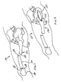
FIG. 7 depicts a schematic diagram of a thigh area wherein a femoral bone is fractured into three bone fragments, none of the bone fragments aligned with the other bone fragments, and the leg is in traction in accordance with principles of the present invention; -
FIG. 8 depicts the thigh area ofFIG. 7 with an incision allowing access to the proximal femoral bone fragment and a bore made into the proximal femoral bone fragment exposing the intramedullary canal of the proximal femoral bone fragment; -
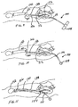
FIG. 9 depicts the thigh area ofFIG 8 with the distal end portion and one flexible shaft portion of the reduction tool ofFIG. 1 inserted within the intramedullary canal of the proximal femoral bone fragment; -
FIG. 10 depicts the thigh area ofFIG. 8 after the reduction tool has been rotated with the second flexible shaft area bent and the distal end portion of the reduction tool hooked into the intramedullary canal of the offset medial bone fragment portion; -
FIG. 11 depicts the thigh area ofFIG 8 with the three femoral bone fragments aligned and reduced with the shaft reduction tool inserted within the aligned intramedullary canal of the femoral bone while a flexible portion of the reduction tool is used to allow the handle of the reduction tool to be moved away from the thigh area; -
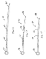
FIGs. 12 to 14 depict side plan views of three different bone reduction tools with different shaft lengths, different placement of flexible shaft areas, and different flexibility of the flexible shaft areas that may be included in a kit in accordance with principles of the present invention. - Referring to the drawings,
FIG. 1 shows abone reduction tool 100. Thetool 100 includes an elongated, generallycylindrical shaft 102 with aproximal end portion 104 and adistal end portion 106. A T-shaped handle 108 is attached to theproximal end portion 104. Theshaft 102 has aninternal bore 110 extending completely along the longitudinal axis of thetool 100 from the T-shaped handle 108 to thedistal end portion 106 which can be seen inFIG. 2 . Thedistal end portion 106 is hook shaped when viewed from the side as best seen inFIG. 3 . - Two
flexible shaft portions medial shaft portion 116 from thedistal end portion 106 and theproximal end portion 104, respectively. Theflexible shaft portions slits 118 and 120. Theslits 118 and 120 extend in a generally helical fashion along the longitudinal axis of thetool 100. Details of theslits 118 and 120, which in this embodiment are similar, are explained with reference toFIG. 4 . Theslit 120 extends from theouter surface 122 of theshaft 102 to thebore 110. Theslit 120 is in the form of a continuous chain of alternating partial links such aspartial links slit 120 includes a bore such as bore 128. Thebore 128 alleviates stress at the end of theslit 120 as the tool flexes as discussed below. - The main difference between the
slit 120 and the slit 118, in addition to the relative location of theslits 118 and 120 along theshaft 102, is the length of theslits 118 and 120. As shown inFIGs. 1 to 3 , theslit 120 extends along theshaft 102 for a greater distance than the slit 118. In this embodiment, theflexible shaft portion 112 extends about 50 mm along theshaft 102 while theflexible shaft portion 114 extends about 100 mm along theshaft 102. The result is that theflexible shaft portion 114 is more flexible than theflexible shaft portion 112. - Specifically, the
entire shaft 102 in this embodiment is made from a resilient material. Accordingly, theslits 118 and 120 effectively weaken the structure of theshaft 102. Consequently, while the alternating partial link structure provides sufficient strength and rigidity for theshaft 102, theslits 118 and 120 allow theflexible shaft portions proximal end portion 104,distal end portion 106 andmedial shaft portion 116. Since theslit 120 extends along theshaft 102 for a greater distance than the slit 118, theflexible shaft portion 114 is more weakened than theflexible shaft portion 112, and thus more easily flexed. The same result may be effected by modifying the relative width of the slits or the pitch of the slits since a given area will become more flexible as the amount of material within the area is decreased. - Thus, as shown in
FIG. 5 , when force is applied to thehandle 108 in the direction of thearrow 128 while movement of thedistal end portion 106 of theshaft 102 is restricted, such as by a bone B, theflexible shaft portion 114 bends while the more rigidproximal end portion 104 andmedial shaft portion 116 remain straight. Thus, as shown inFIG. 6 , the width of theslit 120 at the side of theshaft 102 from which the force is applied, as indicated by thearrow 130, increases while the width of theslit 120 at the opposite side of theshaft 102 decreases. Once theflexible shaft portion 114 has been bent so that the sides of theslit 120 abut each other, most of any additional force applied in an attempt to further bend theshaft 102 will be passed through theflexible shaft portion 114. Thus, the width of theslit 120, along with the orientation and pattern of theslit 120, can be modified to allow for greater or lesser extents of flex. - The relative locations of the
flexible shaft portions flexible shaft portions distal end portion 106 while allowing thehandle 108 to be positioned to allow entry of thetool 100 into a bone while minimizing the impingement of thetool 102 on soft tissues proximate to the bone. This is further described with reference toFIGs. 7 to 11 which illustrate a method of reducing a fracture. - Referring to
FIG. 7 , a partial schematic representation of thethigh area 132 of a patient is shown including ahip bone 134 and thigh (femur)bone 136. Thefemur 136 is fractured into aproximal bone fragment 138 and amedial bone fragment 140 at the fractured ends 142 and 144. Thefemur 136 is further fractured into adistal bone fragment 146 at the fractured ends 148 and 150. Initially, thethigh 132 is placed into traction in accordance with an appropriate procedure. This causes thefractured end 142 of themedial bone fragment 140 to be positioned leftwardly of the fractured end 144 of theproximal bone fragment 138 as viewed inFIG. 7 . Likewise, thefractured end 148 of thedistal bone fragment 146 is positioned leftwardly of thefractured end 150 of themedial bone fragment 140. - Next, the surgical site is prepared in accordance with acceptable practices and an
incision 152 is made in thethigh 132 to expose thefemur 136 as shown inFIG. 8 . Ahole 154 is made in the exposed surface of theproximal bone fragment 138 such as by use of an awl (not shown) to expose the intramedullary canal of theproximal bone fragment 138. The intramedullary canal of theproximal bone fragment 138 is then reamed. - Once the intramedullary canal of the
proximal bone fragment 138 is reamed, thedistal end portion 106 of thetool 100 is inserted through theincision 152 and thehole 154 into the intramedullary canal of theproximal bone fragment 138. As thetool 100 is inserted, theflexible shaft portion 112 may be flexed as necessary to allow thedistal end portion 106 to be moved past minor obstacles as shown inFIG. 9 . - As the
distal end portion 106 approaches thefractured end 142 of themedial bone fragment 140, thetool 100 may be rotated as necessary to "snag" themedial bone fragment 140 as shown inFIG. 10 . The hooked shape of thedistal end portion 106 provides, in conjunction with theflexible shaft portion 112, allows thedistal end portion 106 to be inserted into the intramedullary canal of themedial bone fragment 140 even when significant offset exists between thefractured end 142 and the fractured end 144. Radiography may be used during this step to assist in positioning thetool 100. - The
tool 100 is then manipulated, such as by rotation of thehandle 108, to align thefractured end 142 and the fractured end 144. Radiography may also be used to assist in achieving the desired alignment. The location of theflexible shaft portion 114 allows thehandle 108 to be freely moved without causing damage to the soft tissue surrounding theincision 152 or thefemur 136. - Once the
fractured end 142 and the fractured end 144 are aligned, the traction on thethigh 132 is eased, allowing thefractured end 142 and the fractured end 144 to abut one another. Next, a semi-flexible wire (not shown) (typically 3 mm in diameter) is inserted through thebore 110 in thehandle 108 and theshaft 102. The semi-flexible wire or guidewire is inserted through theshaft 102 and across thefractured end 142 and the fractured end 144 into themedial bone fragment 140. Once the guidewire is positioned thetool 100 is removed and themedial bone fragment 140 is reamed. - The procedure set forth above for alignment of the fractured ends 142 and 144 is then repeated to align the fractured ends 148 and 150. Once the traction is released in this example, the
femur 136 is aligned as shown inFIG. 11 . The length of thetool 100 allows the distal end portion 016 to extend within the intramedullary canal from thehole 154 into thedistal bone portion 146. When thetool 100 is fully inserted within thefemur 136, theflexible shaft portion 114 is located proximate thehole 154 and extends outwardly of theincision 152. This allows thehandle 108 to be freely manoeuvred without causing undue disturbance of the soft tissues surrounding theincision 152 and thehole 154. Thefemur 136 may then be stabilized in accordance with the desired method, thetool 100 may be removed and theincision 152 may be closed. - In one embodiment, a second reduction tool may be used during a procedure. Thus, a kit may include a number of reduction devices, each of the reduction devices having different dimensions and different proportions so as to optimize the ability to reduce different fractures. Accordingly, while in this embodiment the
distal end portion 106 is about 90 mm, the medial shaft portion is about 125 mm and the proximal end portion is about 55 mm, these proportions may be altered for various embodiments. Additionally, more or fewer flexible shaft portions may be provided in a particular tool. - By way of example,
FIG. 12 depicts abone reduction tool 160 which includes ashaft 162 with aflexible shaft portion 164 located between ahandle 166 and a distal end portion 168. Theflexible shaft portion 164 is located closer to thehandle 166 than the distal end portion 168. Thus, thebone reduction tool 160 may be used when the fractured portions of a bone are relatively close in alignment but when access to the intramedullary area of the bone is constrained by soft tissue. - In a further embodiment,
FIG. 13 depicts a bone reduction tool 170 which includes ashaft 172 with aflexible shaft portion 174 located between ahandle 176 and adistal end portion 178. Theflexible shaft portion 174 is located at about the centre of theshaft 176. Additionally, theshaft 172 is shorter than theshaft 162. Thus, the bone reduction tool 170 may be used when the fractured portions of a bone are relatively close in alignment and when the fractured areas are closer to the entry point to the intramedullary area of the fractured bone. - In yet another embodiment,
FIG. 14 depicts abone reduction tool 180 which includes ashaft 182 with aflexible shaft portion 184 located between ahandle 186 and a distal end portion 188. Theflexible shaft portion 184 is located closer to the distal end portion 188 than thehandle 186. Additionally, theshaft 182 is shorter than either theshaft 162 or theshaft 172. Another difference is that theflexible shaft portion 184 is shorter than theflexible shaft portion 164 or theflexible shaft portion 174. Thus, thebone reduction tool 180 may be used when access to the intramedullary area of a bone is less constrained by soft tissue and the fractured portions of a bone are not close in alignment. In a further embodiment, the radius of the bone reduction tools in a kit are varied to allow the use of bone reduction tools with smaller radiuses to be used in thinner intramedullary areas.
Claims (16)
- A bone reduction tool comprising a shaft including
a proximal end portion,
a distal end portion for insertion into a fractured bone,
a first rigid portion located at the distal end portion, and
a first flexible portion located between the first rigid portion and the proximal end portion. - The bone reduction tool of claim 1, in which the shaft includes:a second rigid portion located between the first flexible portion and the proximal end portion;a second flexible portion located between the second rigid portion and the proximal end portion; anda third rigid portion located at the proximal end portion.
- The bone reduction tool of claim 2, in which the distal end portion is curved along its longitudinal axis.
- The bone reduction tool of claim 3, in which the curvature of the distal end portion is greater than the curvature of the second rigid portion
- The bone reduction tool of claim 2, in which the flexibility of the first flexible portion is less than the flexibility of the second flexible portion.
- The bone reduction tool of claim 2, in which the length of the second rigid portion is greater than the length of the third rigid portion, and in which the length of the first rigid portion is greater than the length of the third rigid portion.
- The bone reduction tool of claim 1, which includes a bore extending within the shaft for receiving a guide wire within it.
- The bone reduction tool of claim 7, in which the first flexible portion comprises a first slit extending through the shaft to the bore.
- The bone reduction tool of claim 8, in which:the first slit extends helically about the longitudinal axis of the first flexible portion;the second flexible portion comprises a second slit helically extending about the longitudinal axis of the second flexible portion; andthe second slit extends along the longitudinal axis of the second flexible portion for a distance greater than the distance which the first slit extends along the longitudinal axis of the first flexible portion.
- A bone reduction tool comprising:a shaft with a rigid distal end portion, a rigid proximal end portion, and at least one flexible portion located between the rigid distal end portion and the rigid proximal end portion; anda handle operatively connected to the rigid proximal end portion.
- The bone reduction tool of claim 10, in which the at least one flexible portion comprises a first flexible portion and a second flexible portion, the first flexible portion positioned near the rigid distal end portion and the second flexible portion positioned adjacent to the rigid proximal end portion, and in which the shaft includes a medial rigid portion located between the first flexible portion and the second flexible portion.
- The bone reduction tool of claim 11, in which the first flexible portion and the second flexible portion are connected to the medial rigid portion.
- The bone reduction tool of claim 11, in which the first flexible portion comprises a slot extending circumferentially and longitudinally about the shaft.
- The bone reduction tool of claim 13, in which the shaft is hollow and the slot extends from the outer surface of the shaft to an inner surface of the shaft.
- The bone reduction tool of claim 11, in which the second flexible portion has a flexibility greater than the flexibility of the first flexible portion, and in which the medial rigid portion has a length greater than the length of the rigid distal end portion.
- The bone reduction tool of claim 10, in which the rigid distal end portion includes a hook portion.
Applications Claiming Priority (1)
| Application Number | Priority Date | Filing Date | Title |
|---|---|---|---|
| US11/657,830 US8961522B2 (en) | 2007-01-25 | 2007-01-25 | Flexible shaft reduction tool |
Publications (2)
| Publication Number | Publication Date |
|---|---|
| EP1949865A1 true EP1949865A1 (en) | 2008-07-30 |
| EP1949865B1 EP1949865B1 (en) | 2011-06-22 |
Family
ID=39316360
Family Applications (1)
| Application Number | Title | Priority Date | Filing Date |
|---|---|---|---|
| EP08250204A Not-in-force EP1949865B1 (en) | 2007-01-25 | 2008-01-16 | Flexible shaft bone reduction tool |
Country Status (3)
| Country | Link |
|---|---|
| US (1) | US8961522B2 (en) |
| EP (1) | EP1949865B1 (en) |
| AT (1) | ATE513520T1 (en) |
Families Citing this family (13)
| Publication number | Priority date | Publication date | Assignee | Title |
|---|---|---|---|---|
| WO2011067668A1 (en) * | 2009-12-01 | 2011-06-09 | Dalhousie University | Steerable femoral fracture reduction device |
| US9579132B2 (en) * | 2010-02-24 | 2017-02-28 | William R. Krause | Flexible intramedullary nail |
| US10883532B2 (en) | 2013-03-14 | 2021-01-05 | William R. Krause | Flexible shaft for use as an internal splint for industrial application |
| US12161370B2 (en) | 2013-03-14 | 2024-12-10 | William R. Krause | Flexible connecting rod for industrial applications |
| US10080596B2 (en) | 2013-12-09 | 2018-09-25 | Acumed Llc | Hip fixation with load-controlled dynamization |
| US9526542B2 (en) | 2014-05-07 | 2016-12-27 | Acumed Llc | Hip fixation with load-controlled dynamization |
| WO2015089083A1 (en) | 2013-12-09 | 2015-06-18 | Acumed Llc | Plate-based compliant hip fixation system |
| PT3079612T (en) | 2013-12-09 | 2020-07-16 | Acumed Llc | Nail-based compliant hip fixation system |
| US9433451B2 (en) * | 2013-12-09 | 2016-09-06 | Acumed Llc | Hip fixation system with a compliant fixation element |
| US12285196B2 (en) * | 2015-07-15 | 2025-04-29 | Conventus Orthopaedics, Inc. | Flexible bone implant |
| US11071576B2 (en) * | 2015-10-27 | 2021-07-27 | Spinal Simplicity, Llc | Flexible guide wire with tantalum marker |
| US9895177B2 (en) | 2016-01-15 | 2018-02-20 | ARTHREX, GmbH | Bone fixation device for treatment of femoral fractures |
| CN105997214A (en) * | 2016-06-29 | 2016-10-12 | 江苏艾迪尔医疗科技股份有限公司 | Intramedullary interlocking internal nail |
Citations (4)
| Publication number | Priority date | Publication date | Assignee | Title |
|---|---|---|---|---|
| US4800873A (en) * | 1987-08-31 | 1989-01-31 | Audell Robert A | Method for setting fractures |
| US5879352A (en) * | 1994-10-14 | 1999-03-09 | Synthes (U.S.A.) | Osteosynthetic longitudinal alignment and/or fixation device |
| EP1018318A1 (en) * | 1999-01-07 | 2000-07-12 | Synos-Stiftung zur Förderung der Orthopädischen Chirurgie | Intramedullary nail |
| WO2003068090A1 (en) | 2002-02-11 | 2003-08-21 | Smith & Nephew, Inc. | Image-guided fracture reduction |
Family Cites Families (16)
| Publication number | Priority date | Publication date | Assignee | Title |
|---|---|---|---|---|
| DE1260077B (en) | 1965-04-01 | 1968-02-01 | Ortopedia Gmbh | Instrument for performing nailing in the event of bone fractures |
| US5122146A (en) | 1988-02-04 | 1992-06-16 | Pfizer Hospital Products Group, Inc. | Apparatus for reducing a fracture |
| AT393617B (en) | 1989-10-25 | 1991-11-25 | Ender Hans Georg | INSTRUMENTARIUM FOR REPOSITION AND FIXATION OF PER- AND SUBTROCHANTER FRACTURES |
| US5174302A (en) | 1990-12-04 | 1992-12-29 | Cordis Corporation | Variable radiopacity guidewire with spaced highly radiopaque regions |
| GB9026592D0 (en) * | 1990-12-06 | 1991-01-23 | Meswania Jayantilal M | Surgical instrument |
| US5509919A (en) | 1993-09-24 | 1996-04-23 | Young; Merry A. | Apparatus for guiding a reaming instrument |
| US5488761A (en) * | 1994-07-28 | 1996-02-06 | Leone; Ronald P. | Flexible shaft and method for manufacturing same |
| US5624447A (en) | 1995-03-20 | 1997-04-29 | Othy, Inc. | Surgical tool guide and entry hole positioner |
| WO1997003611A1 (en) * | 1995-07-18 | 1997-02-06 | Edwards, Garland, U. | Flexible shaft |
| US5951561A (en) | 1998-06-30 | 1999-09-14 | Smith & Nephew, Inc. | Minimally invasive intramedullary nail insertion instruments and method |
| US6074392A (en) | 1998-09-01 | 2000-06-13 | Durham; Alfred A. | Method and devices for use in bone fixation procedures |
| US6261289B1 (en) * | 1998-10-26 | 2001-07-17 | Mark Levy | Expandable orthopedic device |
| WO2001034045A1 (en) * | 1999-11-11 | 2001-05-17 | Synthes Ag Chur | Radially expandable intramedullary nail |
| US6875219B2 (en) * | 2003-02-14 | 2005-04-05 | Yves P. Arramon | Bone access system |
| BRPI0413472A (en) | 2003-08-13 | 2006-10-17 | Synthes Gmbh | curved positioning and introducing instrument for inserting a guidewire into the femur, process of positioning an opening guidewire into an intramedullary canal of a femur with an instrument, and instrument cluster |
| US7470279B2 (en) | 2004-02-27 | 2008-12-30 | Jackson Roger P | Orthopedic implant rod reduction tool set and method |
-
2007
- 2007-01-25 US US11/657,830 patent/US8961522B2/en not_active Expired - Fee Related
-
2008
- 2008-01-16 EP EP08250204A patent/EP1949865B1/en not_active Not-in-force
- 2008-01-16 AT AT08250204T patent/ATE513520T1/en not_active IP Right Cessation
Patent Citations (4)
| Publication number | Priority date | Publication date | Assignee | Title |
|---|---|---|---|---|
| US4800873A (en) * | 1987-08-31 | 1989-01-31 | Audell Robert A | Method for setting fractures |
| US5879352A (en) * | 1994-10-14 | 1999-03-09 | Synthes (U.S.A.) | Osteosynthetic longitudinal alignment and/or fixation device |
| EP1018318A1 (en) * | 1999-01-07 | 2000-07-12 | Synos-Stiftung zur Förderung der Orthopädischen Chirurgie | Intramedullary nail |
| WO2003068090A1 (en) | 2002-02-11 | 2003-08-21 | Smith & Nephew, Inc. | Image-guided fracture reduction |
Also Published As
| Publication number | Publication date |
|---|---|
| EP1949865B1 (en) | 2011-06-22 |
| US8961522B2 (en) | 2015-02-24 |
| US20080183170A1 (en) | 2008-07-31 |
| ATE513520T1 (en) | 2011-07-15 |
Similar Documents
| Publication | Publication Date | Title |
|---|---|---|
| EP1949865B1 (en) | Flexible shaft bone reduction tool | |
| US12396766B2 (en) | Osteosynthesis device | |
| JP4932715B2 (en) | Intramedullary rod with spiral flutes | |
| US5053035A (en) | Flexible intramedullary fixation rod | |
| US11344344B2 (en) | Proximal femur hook plate | |
| US20200107866A1 (en) | Device For Osteosyntheses Or Arthrodesis Of Two-Bone Parts, In Particular Of The Hand And/Or Foot | |
| JP4762575B2 (en) | Tunnel notch and guidewire delivery device and method for preparing a bone tunnel | |
| US8795286B2 (en) | Methods and devices for treating a structural bone and joint deformity | |
| US9060820B2 (en) | Segmented intramedullary fracture fixation devices and methods | |
| EP2938279B1 (en) | Alignment guide system | |
| US20110282346A1 (en) | Fracture Fixation Device, Tools and Methods | |
| US20140074093A9 (en) | Straight intramedullary fracture fixation devices and methods | |
| US20110257652A1 (en) | Intramedullary fixation device and methods for bone fixation and stabilization | |
| JP2011523889A (en) | Device, tool and method for fixing fractures | |
| JP2012504027A (en) | Bone fixation device, tool and method | |
| JP2009525833A (en) | Method and instrument for fracture fixation | |
| WO2018183884A1 (en) | Bone fixation system, assembly, devices, insertion guides, and methods of use | |
| US20100234846A1 (en) | Intramedullary radial head locking pin implant | |
| US11779323B2 (en) | Single use radiolucent stabilizing retractor system | |
| US12440200B2 (en) | Stabilizing retractor system | |
| US9408614B2 (en) | Olecranon fracture fixation system | |
| JP2008539910A (en) | Osteosynthesis device | |
| JP4417303B2 (en) | Osteotomy guide | |
| Poyanli et al. | Use of provisional K wires instead of Poller screws for treatment of diametaphyseal fractures of the distal femur and proximal and distal tibia | |
| WO2000047119A1 (en) | Bone fracture therapeutic implement |
Legal Events
| Date | Code | Title | Description |
|---|---|---|---|
| PUAI | Public reference made under article 153(3) epc to a published international application that has entered the european phase |
Free format text: ORIGINAL CODE: 0009012 |
|
| AK | Designated contracting states |
Kind code of ref document: A1 Designated state(s): AT BE BG CH CY CZ DE DK EE ES FI FR GB GR HR HU IE IS IT LI LT LU LV MC MT NL NO PL PT RO SE SI SK TR |
|
| AX | Request for extension of the european patent |
Extension state: AL BA MK RS |
|
| 17P | Request for examination filed |
Effective date: 20090105 |
|
| AKX | Designation fees paid |
Designated state(s): AT BE BG CH CY CZ DE DK EE ES FI FR GB GR HR HU IE IS IT LI LT LU LV MC MT NL NO PL PT RO SE SI SK TR |
|
| GRAP | Despatch of communication of intention to grant a patent |
Free format text: ORIGINAL CODE: EPIDOSNIGR1 |
|
| GRAS | Grant fee paid |
Free format text: ORIGINAL CODE: EPIDOSNIGR3 |
|
| GRAA | (expected) grant |
Free format text: ORIGINAL CODE: 0009210 |
|
| AK | Designated contracting states |
Kind code of ref document: B1 Designated state(s): AT BE BG CH CY CZ DE DK EE ES FI FR GB GR HR HU IE IS IT LI LT LU LV MC MT NL NO PL PT RO SE SI SK TR |
|
| REG | Reference to a national code |
Ref country code: GB Ref legal event code: FG4D |
|
| REG | Reference to a national code |
Ref country code: CH Ref legal event code: EP Ref country code: CH Ref legal event code: NV Representative=s name: E. BLUM & CO. AG PATENT- UND MARKENANWAELTE VSP |
|
| REG | Reference to a national code |
Ref country code: IE Ref legal event code: FG4D |
|
| REG | Reference to a national code |
Ref country code: DE Ref legal event code: R096 Ref document number: 602008007764 Country of ref document: DE Effective date: 20110804 |
|
| REG | Reference to a national code |
Ref country code: NL Ref legal event code: VDEP Effective date: 20110622 |
|
| PG25 | Lapsed in a contracting state [announced via postgrant information from national office to epo] |
Ref country code: NO Free format text: LAPSE BECAUSE OF FAILURE TO SUBMIT A TRANSLATION OF THE DESCRIPTION OR TO PAY THE FEE WITHIN THE PRESCRIBED TIME-LIMIT Effective date: 20110922 Ref country code: LT Free format text: LAPSE BECAUSE OF FAILURE TO SUBMIT A TRANSLATION OF THE DESCRIPTION OR TO PAY THE FEE WITHIN THE PRESCRIBED TIME-LIMIT Effective date: 20110622 Ref country code: HR Free format text: LAPSE BECAUSE OF FAILURE TO SUBMIT A TRANSLATION OF THE DESCRIPTION OR TO PAY THE FEE WITHIN THE PRESCRIBED TIME-LIMIT Effective date: 20110622 Ref country code: SE Free format text: LAPSE BECAUSE OF FAILURE TO SUBMIT A TRANSLATION OF THE DESCRIPTION OR TO PAY THE FEE WITHIN THE PRESCRIBED TIME-LIMIT Effective date: 20110622 |
|
| PG25 | Lapsed in a contracting state [announced via postgrant information from national office to epo] |
Ref country code: LV Free format text: LAPSE BECAUSE OF FAILURE TO SUBMIT A TRANSLATION OF THE DESCRIPTION OR TO PAY THE FEE WITHIN THE PRESCRIBED TIME-LIMIT Effective date: 20110622 Ref country code: SI Free format text: LAPSE BECAUSE OF FAILURE TO SUBMIT A TRANSLATION OF THE DESCRIPTION OR TO PAY THE FEE WITHIN THE PRESCRIBED TIME-LIMIT Effective date: 20110622 Ref country code: AT Free format text: LAPSE BECAUSE OF FAILURE TO SUBMIT A TRANSLATION OF THE DESCRIPTION OR TO PAY THE FEE WITHIN THE PRESCRIBED TIME-LIMIT Effective date: 20110622 Ref country code: FI Free format text: LAPSE BECAUSE OF FAILURE TO SUBMIT A TRANSLATION OF THE DESCRIPTION OR TO PAY THE FEE WITHIN THE PRESCRIBED TIME-LIMIT Effective date: 20110622 Ref country code: CY Free format text: LAPSE BECAUSE OF FAILURE TO SUBMIT A TRANSLATION OF THE DESCRIPTION OR TO PAY THE FEE WITHIN THE PRESCRIBED TIME-LIMIT Effective date: 20110622 Ref country code: GR Free format text: LAPSE BECAUSE OF FAILURE TO SUBMIT A TRANSLATION OF THE DESCRIPTION OR TO PAY THE FEE WITHIN THE PRESCRIBED TIME-LIMIT Effective date: 20110923 |
|
| PG25 | Lapsed in a contracting state [announced via postgrant information from national office to epo] |
Ref country code: BE Free format text: LAPSE BECAUSE OF FAILURE TO SUBMIT A TRANSLATION OF THE DESCRIPTION OR TO PAY THE FEE WITHIN THE PRESCRIBED TIME-LIMIT Effective date: 20110622 Ref country code: NL Free format text: LAPSE BECAUSE OF FAILURE TO SUBMIT A TRANSLATION OF THE DESCRIPTION OR TO PAY THE FEE WITHIN THE PRESCRIBED TIME-LIMIT Effective date: 20110622 |
|
| PG25 | Lapsed in a contracting state [announced via postgrant information from national office to epo] |
Ref country code: EE Free format text: LAPSE BECAUSE OF FAILURE TO SUBMIT A TRANSLATION OF THE DESCRIPTION OR TO PAY THE FEE WITHIN THE PRESCRIBED TIME-LIMIT Effective date: 20110622 Ref country code: IS Free format text: LAPSE BECAUSE OF FAILURE TO SUBMIT A TRANSLATION OF THE DESCRIPTION OR TO PAY THE FEE WITHIN THE PRESCRIBED TIME-LIMIT Effective date: 20111022 Ref country code: PT Free format text: LAPSE BECAUSE OF FAILURE TO SUBMIT A TRANSLATION OF THE DESCRIPTION OR TO PAY THE FEE WITHIN THE PRESCRIBED TIME-LIMIT Effective date: 20111024 Ref country code: CZ Free format text: LAPSE BECAUSE OF FAILURE TO SUBMIT A TRANSLATION OF THE DESCRIPTION OR TO PAY THE FEE WITHIN THE PRESCRIBED TIME-LIMIT Effective date: 20110622 |
|
| PG25 | Lapsed in a contracting state [announced via postgrant information from national office to epo] |
Ref country code: SK Free format text: LAPSE BECAUSE OF FAILURE TO SUBMIT A TRANSLATION OF THE DESCRIPTION OR TO PAY THE FEE WITHIN THE PRESCRIBED TIME-LIMIT Effective date: 20110622 Ref country code: PL Free format text: LAPSE BECAUSE OF FAILURE TO SUBMIT A TRANSLATION OF THE DESCRIPTION OR TO PAY THE FEE WITHIN THE PRESCRIBED TIME-LIMIT Effective date: 20110622 Ref country code: RO Free format text: LAPSE BECAUSE OF FAILURE TO SUBMIT A TRANSLATION OF THE DESCRIPTION OR TO PAY THE FEE WITHIN THE PRESCRIBED TIME-LIMIT Effective date: 20110622 |
|
| REG | Reference to a national code |
Ref country code: DE Ref legal event code: R082 Ref document number: 602008007764 Country of ref document: DE Representative=s name: BOEHMERT & BOEHMERT, DE Ref country code: DE Ref legal event code: R082 Ref document number: 602008007764 Country of ref document: DE Representative=s name: BOEHMERT & BOEHMERT ANWALTSPARTNERSCHAFT MBB -, DE |
|
| PLBE | No opposition filed within time limit |
Free format text: ORIGINAL CODE: 0009261 |
|
| STAA | Information on the status of an ep patent application or granted ep patent |
Free format text: STATUS: NO OPPOSITION FILED WITHIN TIME LIMIT |
|
| PGFP | Annual fee paid to national office [announced via postgrant information from national office to epo] |
Ref country code: FR Payment date: 20120202 Year of fee payment: 5 Ref country code: CH Payment date: 20120112 Year of fee payment: 5 |
|
| 26N | No opposition filed |
Effective date: 20120323 |
|
| PGFP | Annual fee paid to national office [announced via postgrant information from national office to epo] |
Ref country code: DE Payment date: 20120111 Year of fee payment: 5 |
|
| PG25 | Lapsed in a contracting state [announced via postgrant information from national office to epo] |
Ref country code: DK Free format text: LAPSE BECAUSE OF FAILURE TO SUBMIT A TRANSLATION OF THE DESCRIPTION OR TO PAY THE FEE WITHIN THE PRESCRIBED TIME-LIMIT Effective date: 20110622 |
|
| PGFP | Annual fee paid to national office [announced via postgrant information from national office to epo] |
Ref country code: IT Payment date: 20120118 Year of fee payment: 5 Ref country code: GB Payment date: 20120111 Year of fee payment: 5 |
|
| REG | Reference to a national code |
Ref country code: DE Ref legal event code: R097 Ref document number: 602008007764 Country of ref document: DE Effective date: 20120323 |
|
| PG25 | Lapsed in a contracting state [announced via postgrant information from national office to epo] |
Ref country code: MC Free format text: LAPSE BECAUSE OF NON-PAYMENT OF DUE FEES Effective date: 20120131 |
|
| REG | Reference to a national code |
Ref country code: IE Ref legal event code: MM4A |
|
| PG25 | Lapsed in a contracting state [announced via postgrant information from national office to epo] |
Ref country code: IE Free format text: LAPSE BECAUSE OF NON-PAYMENT OF DUE FEES Effective date: 20120116 |
|
| PG25 | Lapsed in a contracting state [announced via postgrant information from national office to epo] |
Ref country code: ES Free format text: LAPSE BECAUSE OF FAILURE TO SUBMIT A TRANSLATION OF THE DESCRIPTION OR TO PAY THE FEE WITHIN THE PRESCRIBED TIME-LIMIT Effective date: 20111003 |
|
| PG25 | Lapsed in a contracting state [announced via postgrant information from national office to epo] |
Ref country code: BG Free format text: LAPSE BECAUSE OF FAILURE TO SUBMIT A TRANSLATION OF THE DESCRIPTION OR TO PAY THE FEE WITHIN THE PRESCRIBED TIME-LIMIT Effective date: 20110922 |
|
| PG25 | Lapsed in a contracting state [announced via postgrant information from national office to epo] |
Ref country code: MT Free format text: LAPSE BECAUSE OF FAILURE TO SUBMIT A TRANSLATION OF THE DESCRIPTION OR TO PAY THE FEE WITHIN THE PRESCRIBED TIME-LIMIT Effective date: 20110622 |
|
| REG | Reference to a national code |
Ref country code: CH Ref legal event code: PL |
|
| GBPC | Gb: european patent ceased through non-payment of renewal fee |
Effective date: 20130116 |
|
| REG | Reference to a national code |
Ref country code: FR Ref legal event code: ST Effective date: 20130930 |
|
| PG25 | Lapsed in a contracting state [announced via postgrant information from national office to epo] |
Ref country code: CH Free format text: LAPSE BECAUSE OF NON-PAYMENT OF DUE FEES Effective date: 20130131 Ref country code: DE Free format text: LAPSE BECAUSE OF NON-PAYMENT OF DUE FEES Effective date: 20130801 Ref country code: LI Free format text: LAPSE BECAUSE OF NON-PAYMENT OF DUE FEES Effective date: 20130131 |
|
| REG | Reference to a national code |
Ref country code: DE Ref legal event code: R119 Ref document number: 602008007764 Country of ref document: DE Effective date: 20130801 |
|
| PG25 | Lapsed in a contracting state [announced via postgrant information from national office to epo] |
Ref country code: FR Free format text: LAPSE BECAUSE OF NON-PAYMENT OF DUE FEES Effective date: 20130131 Ref country code: GB Free format text: LAPSE BECAUSE OF NON-PAYMENT OF DUE FEES Effective date: 20130116 |
|
| PG25 | Lapsed in a contracting state [announced via postgrant information from national office to epo] |
Ref country code: IT Free format text: LAPSE BECAUSE OF NON-PAYMENT OF DUE FEES Effective date: 20130116 |
|
| PG25 | Lapsed in a contracting state [announced via postgrant information from national office to epo] |
Ref country code: TR Free format text: LAPSE BECAUSE OF FAILURE TO SUBMIT A TRANSLATION OF THE DESCRIPTION OR TO PAY THE FEE WITHIN THE PRESCRIBED TIME-LIMIT Effective date: 20110622 |
|
| PG25 | Lapsed in a contracting state [announced via postgrant information from national office to epo] |
Ref country code: LU Free format text: LAPSE BECAUSE OF NON-PAYMENT OF DUE FEES Effective date: 20120116 |
|
| PG25 | Lapsed in a contracting state [announced via postgrant information from national office to epo] |
Ref country code: HU Free format text: LAPSE BECAUSE OF FAILURE TO SUBMIT A TRANSLATION OF THE DESCRIPTION OR TO PAY THE FEE WITHIN THE PRESCRIBED TIME-LIMIT Effective date: 20080116 |