EP1947873B1 - Multi-mode network communication system - Google Patents
Multi-mode network communication system Download PDFInfo
- Publication number
- EP1947873B1 EP1947873B1 EP06775530A EP06775530A EP1947873B1 EP 1947873 B1 EP1947873 B1 EP 1947873B1 EP 06775530 A EP06775530 A EP 06775530A EP 06775530 A EP06775530 A EP 06775530A EP 1947873 B1 EP1947873 B1 EP 1947873B1
- Authority
- EP
- European Patent Office
- Prior art keywords
- wired
- equipment
- base station
- unit
- mode
- Prior art date
- Legal status (The legal status is an assumption and is not a legal conclusion. Google has not performed a legal analysis and makes no representation as to the accuracy of the status listed.)
- Active
Links
Images


Classifications
-
- H—ELECTRICITY
- H04—ELECTRIC COMMUNICATION TECHNIQUE
- H04W—WIRELESS COMMUNICATION NETWORKS
- H04W88/00—Devices specially adapted for wireless communication networks, e.g. terminals, base stations or access point devices
- H04W88/08—Access point devices
- H04W88/085—Access point devices with remote components
-
- H—ELECTRICITY
- H04—ELECTRIC COMMUNICATION TECHNIQUE
- H04W—WIRELESS COMMUNICATION NETWORKS
- H04W16/00—Network planning, e.g. coverage or traffic planning tools; Network deployment, e.g. resource partitioning or cells structures
- H04W16/18—Network planning tools
-
- H—ELECTRICITY
- H04—ELECTRIC COMMUNICATION TECHNIQUE
- H04W—WIRELESS COMMUNICATION NETWORKS
- H04W24/00—Supervisory, monitoring or testing arrangements
- H04W24/02—Arrangements for optimising operational condition
-
- H—ELECTRICITY
- H04—ELECTRIC COMMUNICATION TECHNIQUE
- H04W—WIRELESS COMMUNICATION NETWORKS
- H04W92/00—Interfaces specially adapted for wireless communication networks
- H04W92/02—Inter-networking arrangements
Definitions
- the present invention relates to the network communication technology and in particular to a multimode network communication system.
- networks deploying different modes are emerging, including wireless network in different modes and wired network in different modes.
- operators pursue to implement networking in accordance with networks in different modes, such as networking based on wireless network in different modes, wired network in different modes and integration of wireless network in different modes and wired network in different modes.
- wireless network is required to be planned and optimized in accordance with geographical environment and wireless channel transmission environment of this region, so that the most reasonable location for a wireless base station may be determined.
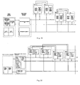
- the site selection for the base station in a Global System for Mobile communications, GSM, wireless cellular network is shown in Figure 1
- the site selection for the base station in a Worldwide Interoperability for Microwave Access, WiMAX, wireless cellular network is shown in Figure 2 .
- the site selection for the base station in wireless network in different modes varies.
- two wireless networks are to be constructed, i.e. a GSM wireless cellular network optimized with GSM wireless cellular network optimization method and a WiMAX wireless cellular network optimized with GSM WiMAX wireless cellular network optimization method, the optimized network is as shown in Figure 3 .
- Operator A constructs firstly a wireless cellular network covering a region by adopting mode A wireless access technology, for example GSM, and then desires to upgrade the original mode A wireless equipment (For example, a mode B wireless access card is inserted into the original mode A wireless base station.) into multimode wireless integrated access equipment, in the same region users adopting mode A wireless access technology are supported, users adopting mode B wireless access technology are introduced, and therefore a mode B wireless cellular network (for example WiMAX) overlaps the original mode A wireless cellular network.
- mode A wireless access technology for example GSM
- the site selection for the original mode A wireless equipment is in conflict with that for the newly added mode B wireless base station due to the difference between the plan of cellular networks in different modes.
- the distance between the optimal site of the original mode A wireless equipment and the optimal site of the newly added mode B wireless base station may be up to several kilometers. It is a problem whether to perform the site selection in accordance with mode A wireless network plan and place the upgraded multimode wireless integrated access equipment at the original site, or to perform another site selection in accordance with mode B wireless network plan. If the site selection is performed in accordance with mode A wireless network plan, it is an optimal site for mode A wireless cellular network but not an optimal site for mode B wireless cellular network.
- the site selection is performed in accordance with mode B wireless network plan, it is an optimal site for mode B wireless cellular network but not an optimal site for mode A wireless cellular network and furthermore operators need to take the land on lease and construct machine rooms for the mode B wireless cellular network base station and mode A wireless cellular network equipment.
- the mode B wireless base station may not be obtained by upgrading the mode A wireless equipment. Therefore, a new site selection needs to be performed for mode B wireless base station which also needs to be newly constructed.
- Both the mode B wireless cellular base station and the mode A wireless cellular equipment need to be supplied with Alternating Current , AC, power, and provided with backup power supplies by using battery pack, Un-interruptible Power Supply, UPS, electric generator set or the second mains power. Operators usually need to take the land on lease and construct machine rooms for the mode B wireless cellular network base station and mode A wireless cellular network equipment. Therefore, if cable resources of the mode A wireless cellular network and the mode B wireless cellular network can not be efficiently utilized by sharing, it is difficult to uniformly maintain the mode B wireless cellular network base station and the mode A wireless cellular equipment, which may result in a high maintenance cost.
- wired network is required to be planned and optimized in accordance with geographical environment and wireless channel transmission environment of this region, so that an optimal site for a wireless base station may be determined.
- the site selection for the corresponding Digital Subscriber Line Access Multiplexer, DSLAM, equipment is as shown in Figure 4 .
- the site selection for the corresponding access equipment is as shown in Figure 5 .
- two wired access networks need to be constructed, i.e. a DSL broadband access network optimized with DSL broadband access network optimization method and an HFC wired access network optimized with HFC network optimization method.
- Operator B constructs firstly a wired access network covering a region by adopting mode A (for example DSL) wireless access technology, and then desires to upgrade the original mode A wired equipment (For example, a mode B wired access card is inserted into the original mode A wired equipment.) into multimode wired integrated access equipment, in the same region users adopting mode A wireless access technology are supported, users adopting mode B wired access technology are introduced, and therefore a mode B wired access network (for example HFC) overlaps the original mode A wired access network.
- site selection for the original mode A wired equipment is in conflict with that for the newly added mode B wired equipment due to the difference between the plan of cellular networks in different modes.
- the distance between the optimal site of the original mode A wired equipment and the optimal site of the newly added mode B wired equipment may be up to several kilometers.
- the site selection for the upgraded multimode wired integrated access equipment is performed in accordance with mode A wired access network plan, it is an optimal site for mode A wired access network but not an optimal site for mode B wired access network. If the site selection is performed in accordance with mode B wired access network plan, it is an optimal site for mode B wired access network but not an optimal site for mode A wired access network.
- Both the mode A wired access equipment and the mode B wired access equipment need to be supplied with AC power, and provided with backup power supplies by using battery pack, UPS, electric generator set or the second mains power. Operators usually need to take the land on lease and construct machine rooms for the wired access equipment. Cable resources of the mode A wired access network and the mode B wired access network may not be efficiently utilized by sharing, and therefore it is difficult to uniformly maintain the mode B wired access equipment, which may result in a high maintenance cost.
- wirelesss network is required to be planned and optimized in accordance with geographical environment and wireless channel transmission environment of this region, so that an optimal site for a wireless base station may be determined.
- the site selection in Beijing is implemented through wireless access technology.
- wired network is required to be planned and optimized in accordance with geographical environment and wired channel transmission environment of this region, so that an optimal site for a wired base station may be determined.
- Figure 2 illustrates the site selection for the wired equipment in Beijing by adopting wired access technology.
- a wired access network for example DSL broadband access network, optimized with wired network optimization method
- a wireless access network for example WiMAX cellular access network, optimized with wireless access network optimization method
- Operator B constructs firstly a wireless access network covering a region by adopting wireless access technology, and then desires to upgrade the original wireless equipment into the wireless and wired integrated access equipment, for example adding a wired access card in the original base station, in the same region users adopting wireless access technology are supported, users adopting wired access technology are introduced.
- site selection for the original wireless equipment is in conflict with that for the newly added wired equipment due to the difference between the plan of wireless network and that of wired network.
- the distance between the optimal site of the original wireless equipment and the optimal site of the newly added wired equipment may be up to several kilometers.
- the site selection for the upgraded wireless and wired integrated access equipment is performed in accordance with wireless access network plan, it is an optimal site for wireless access network but not an optimal site for wired access network. If the site selection is performed in accordance with wired access network plan, it is an optimal site for wired access network but not an optimal site for wireless access network. Furthermore, operators need to take the land on lease and construct machine rooms the wireless equipment and wired equipment.
- both the wireless access equipment of wireless access network and the wired equipment of wired access network need to be supplied with AC power, and provided with backup power equipment.
- the investment of the operators for constructing a new wired access network may be greatly increased.
- wired access network can not be constructed by upgrading the original wireless access network, cable resources of wireless access network and the wired access network may not be efficiently utilized by sharing. Therefore it is difficult to uniformly maintain the wired access equipment and wireless access equipment, which may result in a high maintenance cost.
- WO0/30141 A1 discloses a mobile base station system including a central unit and at least one antenna unit.
- the central unit includes radio parts to operate according to two different access standards, the antenna units is detached from the central unit and located geographically separated from the central unit, and in a first optical broadband fiber and a second optical broadband fiber which connect the central unit and the antenna unit.
- the present invention provides a multimode network communication system so that different modes of network equipment newly added may effectively utilize the original network resources and the network maintenance and construction cost may be reduced.
- An object of the present invention is to provide a multimode network communication system so as to overcome the above mentioned problems.
- the objects of the invention are achieved by an arrangement which is characterized by what is stated in the independent claim.
- the preferred embodiments of the invention are disclosed in the dependent claims.
- the distributed equipment technology is adopted to arrange the local communication equipment in the newly added network into the communication equipment in the basic network, and to implement the service functions of the newly added network through message exchange with the remote communication equipment, which solves the problem of site selection conflict between the mode A equipment in the original network and the communication equipment in the newly added network due to the difference of multimode network plan.
- the equipment in the basic network and newly added network are supplied with power by the power supply unit in the basic network, which solves the problem that resources can not be fully utilized and reduces the maintenance cost.
- the operator A may select a site for the wired equipment in accordance with wired network plan, construct a wired access network. Then the operator A may select a site for the base station outdoor unit in accordance with demands for wireless access in the market and the wireless network plan.
- the base station access processing unit, convergence unit and remote power supply unit are added and interconnected with the base station outdoor unit, which constitutes complete wired and wireless integrated access equipment, helps constitute a wired and wireless access network in the same region and ensures an optimal plan for the wired and wireless networks.
- the base station remote equipment do not need AC power supply, do not need backup power supply by using battery pack, UPS, electric generator set or the second mains power.
- the base station remote equipment may be sealed and placed outdoor or underground and do not need machine rooms. Further, original cables, such as telephone twisted pair, of the fixed network operators may be reused for the wired and wireless base station remote equipment, which reduce the cost of network construction and maintenance.
- the operator B may select a site for the wired equipment in accordance with mode A wired network plan, and construct a wired access network. Then the operator B may select a site for the mode B wired terminal in accordance with demands for wired access in the market and the mode B wired network plan.
- the wired access processing unit, convergence unit and remote power supply unit are added and interconnected with the mode B wired terminal, which constitutes a complete multimode wired integrated access equipment, helps constitute a multimode wired access network in the same region and ensures an optimal plan for both the mode A wired and mode B wired networks.
- the mode B wired remote devices do not need AC power supply, do not need backup power supply by using battery pack, UPS, electric generator set or the second mains power. (Power backup is provided at the mode A wired equipment side) Therefore, the cost of construction and maintenance of the mode B wired network may be reduced.
- Figure 1 is a schematic diagram showing the base station site selection of the GSM wireless network plan.
- Figure 2 is schematic diagram showing the base station site selection of the WiMAX wireless network plan.
- Figure 3 is schematic diagram showing the conflict in the base station site selection of Figure 1 and Figure 2 .
- Figure 4 is a schematic diagram showing the base station site selection of the DSL broadband access network plan.
- Figure 5 is a schematic diagram showing the base station site selection of the HFC wired access network plan.
- Figure 6 is a schematic diagram showing the conflict in base station site selection of the access equipment of Figure 4 and Figure 5 .
- Figure 7 is a schematic diagram showing the base station site selection of the wireless network plan.
- Figure 8 is a schematic diagram showing the base station site selection of the wired network plan.
- Figure 9 is a schematic diagram showing the conflict in the base station site selection of Figure 7 and Figure 8 .
- Figure 10 is a schematic diagram showing the base station.
- Figure 11 is schematic diagram 1 of the star structure showing the multimode wireless integrated access system.
- Figure 12 is schematic diagram 2 of the star structure showing the multimode wireless integrated access system.
- Figure 13 is schematic diagram 3 of the star structure showing the multimode wireless integrated access system.
- Figure 14 is schematic diagram 4 of the star structure showing the multimode wireless integrated access system.
- Figure 15 is schematic diagram 5 of the star structure showing the multimode wireless integrated access system.
- Figure 16 is schematic diagram 1 of the tree structure showing the multimode wireless integrated access system.
- Figure 17 is schematic diagram 2 of the tree structure showing the multimode wireless integrated access system.
- Figure 18 is schematic diagram 3 of the tree structure showing the multimode wireless integrated access system.
- Figure 19 is schematic diagram 4 of the tree structure showing the multimode wireless integrated access system.
- Figure 20 is schematic diagram 5 of the tree structure showing the multimode wireless integrated access system.
- Figure 21 is schematic diagram 1 of the ring structure showing the multimode wireless integrated access system.
- Figure 22 is schematic diagram 2 of the ring structure showing the multimode wireless integrated access system.
- Figure 23 is schematic diagram 3 of the ring structure showing the multimode wireless integrated access system.
- Figure 24 is schematic diagram 1 of the net structure showing the multimode wireless integrated access system.
- Figure 25 is schematic diagram 2 of the net structure showing the multimode wireless integrated access system.
- Figure 26 is schematic diagram 1 of the star structure showing the multimode wired integrated access system.
- Figure 27 is schematic diagram 2 of the star structure showing the multimode wired integrated access system.
- Figure 28 is schematic diagram 3 of the star structure showing the multimode wired integrated access system.
- Figure 29 is schematic diagram 4 of the star structure showing the multimode wired integrated access system.
- Figure 30 is schematic diagram 5 of the star structure showing the multimode wired integrated access system.
- Figure 31 is schematic diagram 1 of the tree structure showing the multimode wired integrated access system.
- Figure 32 is schematic diagram 2 of the tree structure showing the multimode wired integrated access system.
- Figure 33 is schematic diagram 3 of the tree structure showing the multimode wired integrated access system.
- Figure 34 is schematic diagram 4 of the tree structure showing the multimode wired integrated access system.
- Figure 35 is schematic diagram 5 of the tree structure showing the multimode wired integrated access system.
- Figure 36 is schematic diagram 1 of the ring structure showing the multimode wired integrated access system.
- Figure 37 is schematic diagram 2 of the ring structure showing the multimode wired integrated access system.
- Figure 38 is schematic diagram 3 of the ring structure showing the multimode wired integrated access system.
- Figure 39 is schematic diagram 1 of the net structure showing the multimode wired integrated access system.
- Figure 40 is schematic diagram 2 of the net structure showing the multimode wired integrated access system.
- the present invention is to solve the conflict in selecting site of networking in different modes.
- the multimode network communication system of the present invention includes the first equipment based on the first mode and the second equipment based on the second mode.
- the second equipment includes local device and remote device; the local device is arranged in the first equipment so that the second equipment of the second mode may utilize the existing first equipment of the first mode to realize some functions.
- the remote device is independent and remotely connected with the first equipment, so as to satisfy the requirement of optimizing the site selection, overcoming the conflict occurring in selecting site of networking in different modes.
- the present invention may satisfy the requirements brought by wireless networking of different modes, wired networking of different modes, integrated wired and wireless networking of different modes.
- the present invention provides respectively multimode wireless integrated access distributed system, multimode wired integrated access distributed system, and multimode wired and wireless integrated access distributed system, etc.
- the multimode wired and wireless integrated access distributed system may include the integrated access distributed system of the first equipment taking the wireless equipment as the first mode and the second equipment taking the wired equipment as the second mode, and the integrated access distributed system of the first equipment taking the wired equipment as the first mode and the second equipment taking the wireless equipment as the second mode.
- the present invention provides a multimode wireless integrated distributed system.
- the system may solve the conflict in selecting the site of the original mode A wireless equipment and the base station of a newly added mode B caused by the planning variance in the multimode wireless network.
- the resources may be fully utilized to lower the constructing and maintenance fee.
- the key point of the system is to divide the newly added mode into two parts of local device and remote device.
- the local device is arranged in the existing wireless equipment, i.e. configured in the same site as that of the existing wireless equipment.
- the remote device may select the optimal site according to the network planning in the new mode; then the remote device is arranged in the optimal site to guarantee the best communication effect of the new mode network.
- the newly added wireless equipment includes mainly base station equipment.
- the base station equipment mainly includes antenna and pre-radio-frequency processing module, post-radio-frequency processing module, intermediate frequency processing module, baseband processing module, wireless data link layer processing module and wireless data upper-link layer processing module; meanwhile, base station equipment also needs the corresponding power supply unit to supply power.
- the local device in the system of the present invention includes at least power supply unit; and the base station access processing unit may also be included.
- the base station access processing unit includes the wireless data upper-link layer processing module, or the wireless data upper-link layer processing module and wireless data link layer processing module, or the wireless data upper-link layer processing module, the wireless data link layer processing module and baseband processing module, or the wireless data upper-link layer processing module, the wireless data link layer processing module, baseband processing module and intermediate frequency processing module, or wireless data upper-link layer processing module, wireless data link layer processing module, baseband processing module, intermediate frequency processing module and post-radio-frequency processing module.
- the remote device i.e. the remote base station equipment, includes base station outdoor unit which includes at least antenna and pre-radio-frequency processing unit and the processing units except that allocated to the local device.
- the local device includes the power supply unit, wireless data upper-link layer processing unit, wireless data link layer processing unit and baseband processing unit
- the remote device then includes intermediate frequency processing unit, post-radio-frequency processing unit and antenna, and pre-radio-frequency processing unit.
- the power supply unit is specifically the central power supply unit.
- the function is to transform the mains inputs (e.g. Alternating Current, (AC), 110V/220V) or the Direct Current, (DC), inputs (e.g. -48V/-60 DC) into high voltage DC outputs, in order to supply power to the local wireless equipment and local equipment, and also to supply power to the remote base station outdoor units through cable line (e.g. twisted pair cable).
- the distance of the remote power supply which can be as far as 2 ⁇ 5 kilometers, is affected by factors such as, the gauge of the wired cable, the number of the cable pairs, the power consumption of the outdoor units, and the output voltage of the power supply unit.
- the central power supply unit also supports the communication between the base station outdoor units. As the out band management path, the central power supply unit may also implement monitoring alarm in both normal or fault state to facilitate the management of the equipment, fault positioning, remote maintenance, etc.
- the remote device may include the remote power supply unit, adapted to transform the high voltage DC inputs (e.g. 270V DC) into low voltage DC to supply power locally for the equipment where the remote power supply unit is arranged, or to continually transmit the high voltage DC from the central power supply unit and supply remotely the power for the next level remote base station outdoor units through the wired cable.
- the high voltage DC inputs e.g. 270V DC
- the central power supply unit adapted to transform the high voltage DC inputs (e.g. 270V DC) into low voltage DC to supply power locally for the equipment where the remote power supply unit is arranged, or to continually transmit the high voltage DC from the central power supply unit and supply remotely the power for the next level remote base station outdoor units through the wired cable.
- the system also includes a convergence unit, adapted to converge the wireless signal received by the base station outdoor processing unit and then access the signal to the base station access processing unit, distribute the signal generated by the base station access processing unit to the base station outdoor processing units and transmit the signal via antenna to wireless access users.
- a convergence unit adapted to converge the wireless signal received by the base station outdoor processing unit and then access the signal to the base station access processing unit, distribute the signal generated by the base station access processing unit to the base station outdoor processing units and transmit the signal via antenna to wireless access users.
- the convergence unit may be arranged in remote or local device. The following are descriptions concerning different situations.
- the convergence unit When set in the local device, the convergence unit converges the wireless signal received by the base station outdoor unit of the remote device and then accesses the signal to the base station access processing unit of the local device, and transmits the signal generated by the base station access processing unit of the local device to the base station outdoor unit of the remote device.
- the convergence unit When set in the remote device while the base station processing unit is set in local device, the convergence unit is remotely connected with the base station access processing unit of local device through the wired cable, and also remotely connected with the base station outdoor unit of the remote device, in order to converge the wireless access signal received by multiple base station outdoor units of remote device, and then transmit the signal to the base station access processing unit of the local device; and transmit the signal generated by the base station access processing unit of local device to the base station outdoor units of the remote device.
- the convergence unit When set in the remote device while the base station processing unit is also set in the remote device, the convergence unit is connected with the base station access processing unit of the remote device through the wired cable, and is remotely connected with the base station outdoor unit of the remote device, in order to converge the wireless access signal received by multiple base station outdoor units of remote device, and then transmit the signal to base station access unit of the remote device; and transmit the signal generated by the base station access processing unit of remote device to the base station outdoor unit of the remote device.
- the base station processing units communicate with the base station outdoor units through the switch convergence unit; the base station processing units may perform mutual aid in providing backup based on the switch convergence unit.
- the switch convergence unit is set in the local or the remote device; the unit converges the wireless access signal received by a base station outdoor unit of remote device, and then selectively accesses the signal to one of the base station access processing units of the local device or the remote device; and transmits the signal generated by the base station access processing unit of the local device or the remote device to the base station outdoor unit of the remote device.
- the switch convergence units in the system of the present invention are set in both local device and remote device; the first switch convergence unit set in the local device is remotely connected with the second switch convergence unit set in the remote device; the second switch convergence unit is also remotely connected with the base station outdoor unit; the second switch convergence unit is adapted to converge the wireless access signal received by multiple base station outdoor units of the remote device and then transmit the signal to the first switch convergence unit; the first switch convergence unit selectively accesses one the base station processing unit of the local device; and transmits the signals generated by the base station processing units of the local device to the second switch convergence unit, then the unit selectively accesses one of the base station outdoor units of the remote device.
- mode A wireless cellular network is taken as basic network; mode B wireless cellular network is taken as newly-added network; the mode A wireless cellular network equipment set in the basic network is taken as the local communication equipment; the rest mode B wireless cellular equipment is taken as the remote communication equipment.
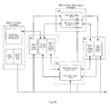
- a first embodiment of the present invention is illustrated in Figure 11 .
- This embodiment includes local mode A wireless equipment, mode B remote base station equipment, convergence unit, mode B base station access processing unit, central power supply unit, remote power supply unit and power backup unit;
- the local mode A wireless equipment includes the wireless equipment of the original mode A wireless cellular network;
- the mode B remote base station equipment includes specifically mode B base station outdoor unit or the integrated equipment of the mode B base station outdoor unit and the remote power supply unit.
- the mode B base station access processing unit and convergence unit are set in the local mode A wireless cellular equipment; the local mode A wireless equipment is to optimize the site according to the mode A wireless network plan; the mode B outdoor unit is set in remote device according to the mode B wireless network optimal site selection, and is remotely connected in star structure with the local mode A wireless equipment via wired cable as fiber or twisted pair cable.
- the mode B base station outdoor units may be remotely interconnected via wired cable; multi-antenna transmit diversity or multi-antenna receive diversity may be constituted among multiple mode B base station outdoor units.
- mode B base station outdoor unit 2 and mode B base station outdoor unit 3 are interconnected in concatenation, constituting dual antenna transmit diversity or dual antenna receive diversity.
- the central power supply unit is set in local mode A wireless cellular network to supply power for the mode B base station access processing unit and the mode B base station outdoor unit 2.
- the remote power supply unit 2 is remotely connected with the central power supply unit to supply power for the mode B base station outdoor unit 2, and is also remotely connected with the lower level remote power supply unit 3 to supply the power for the first level mode B base station outdoor unit 3.
- the remote power supply unit is logically separated from the corresponding mode B base station outdoor unit, but physically separated or integrated, like mode B remote base station - B2 and B3.
- the wired cable for connecting local mode A wireless equipment and mode B remote base station equipment and the cable is logically separated from the power cable, but physically separated or integrated.
- the star, ring, or shared bus connection may be adopted between the central power supply unit and mode B base station outdoor units or remote power supply units.
- the ring connection or the shared bus connection may also be adopted among remote power supply units.
- the mode B base station outdoor unit and the mode B base station access processing unit complete together the wireless access processing, for example, the mode B base station outdoor unit may include radio frequency, intermediate frequency and antenna; and, the base station access processing unit complete both the baseband and wireless data link layer processing.
- the convergence unit converges the wireless access signal received by multiple mode B base station outdoor units and then transmits the signal to mode B base station access processing unit; and distributes the signal generated by the mode B base station access processing unit to multiple mode B base station outdoor units, and then transmits the signal to wireless access users via antenna.
- the central power supply unit transforms the mains or DC inputs into high voltage DC outputs, and supply power for the remote mode B base station outdoor unit via wired cable.
- the central power supply unit also supports the communication among the mode B base station outdoor units.
- the central power supply unit may also implement monitoring alarm in both normal or fault state to facilitate the management of the equipment, fault positioning, remote maintenance, etc.
- the central power supply unit needs to be configured with the power supply unit to backup power.
- the power backup unit may be a battery pack, a UPS, a power generation set, or a second mains power.
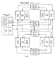
- a second embodiment is illustrated in Figure 12 .
- the difference between the system in Figure 12 and the system in Figure 11 lies in that the convergence unit in Figure 11 is substituted by the switch convergence unit in Figure 12 , and the multiple mode B base station access processing units are added into the mode A wireless equipment.
- the backup of "1+1" mode, "N+1" mode or a resource pool redundancy mode through the switch convergence unit may be made among the mode B base station outdoor units of mode A wireless equipment to further improve the reliability of the mode B wireless network communication.
- a third embodiment is illustrated in Figure 13 .
- the difference of the system in Figure 13 and the system in Figure 11 lies in that the convergence unit of mode A wireless equipment in Figure 11 is set in the remote device of Figure 13 .
- the remote device includes convergence unit and remote power supply unit, and the convergence unit and the remote power supply unit may be simple switches capable of remote power supply, so that the connection between mode A wireless equipment and mode B base station outdoor units may be saved.
- Mode A wireless equipment is to optimize the site according to mode A wireless network plan
- mode B base station outdoor units are to optimize the site according to the mode B wireless network plan.
- the mode B base station outdoor unit is converged by the convergence unit, and is remotely connected with the mode A wireless equipment via wired cable.
- the central power supply unit remotely supplies DC power for the mode B base station remote equipment (2 ⁇ 5 kilometers), similar to the remote power supply shown in Figure 11 ; the remote power supply unit connected with the central power supply unit supplies power for the mode B base station outdoor unit or the integrated equipment of mode B base station outdoor unit and the remote power supply unit.
- the distance is within a certain range, such as 100-200 meters.
- a fourth embodiment is illustrated in Figure 14 .
- the difference between the system in Figure 14 and the system in Figure 13 lies in that the convergence unit in Figure 13 is substituted by the first and second switch convergence units in Figure 14 , and the mode A wireless equipment is connected with remote device via multiple pairs of signals or data lines.
- the backup of "1+1" mode, "N+1" mode or a resource pool redundancy mode through the switch convergence unit may be made among the mode B base station access processing units of mode A wireless equipment, and the mode B base station outdoor units, or of the signals or data lines between the mode A wireless equipment and the second switch convergence unit to ensure the reliability of the mode B wireless network communication.
- a fifth embodiment is illustrated in Figure 15 .
- the difference of the system in Figure 15 and the system in Figure 13 lies in that the mode B base station access processing unit of mode A wireless equipment in Figure 13 is set in the remote device in Figure 15 .
- the mode B base station access processing unit, the switch exchange unit and the remote power supply unit in the remote device are integrated to be independent of the base station outdoor unit device.
- a sixth embodiment is illustrated in Figure 16 .
- the difference of the system in Figure 16 and the system in Figure 15 lies in that the convergence unit in Figure 15 is substituted by switch convergence unit in Figure 16 , and the mode B base station access processing unit is connected with the mode B base station outdoor unit via multiple pairs of signal and data line.
- the backup of "1+1" mode, "N+1" mode or a resource pool redundancy mode through the switch convergence unit may be made among the mode B base station access processing units, and among the mode B base station outdoor units.
- a seventh embodiment is illustrated in Figure 17 .
- mode B base station outdoor unit I and mode B base station outdoor units 2a share one wired cable using frequency division multiplexing or time division multiplexing, and then are remotely connected with mode A wireless equipment;
- mode B base station outdoor unit 2b is a branch from mode B base station outdoor unit 2a, forming a remote tree connection.
- the wired cable remotely connecting local mode A wireless equipment and mode B remote base station equipment, the corresponding signal line and power cable are logically separated but physically separated or integrated.
- the star, ring or shared bus connection may be adopted between the central power supply unit and mode B base station outdoor units; the star, ring or shared bus connection may be also adopted among the remote power supply units.
- the difference of system in Figure 18 and the system in Figure 17 lies in that multiple mode B base station access processing units are added into the system of Figure 18 ; multiple pairs of signal or data line tree connection is adopted between mode A wireless equipment and mode B base station remote equipment.
- the backup of "1+1" mode, "N+1" mode or a resource pool redundancy mode through the switch convergence unit may be made among the mode B base station access processing units of mode A wireless equipment or the mode B base station outdoor units.
- the star, ring or shared bus connection may be adopted between the central power supply unit and mode B base station outdoor unit, or among the remote power supply units; the star, ring or shared bus connection may be also adopted among the remote power supply units.
- the power supply assistance may be implemented among remote power supply units.
- the power assistance may be implemented between the remote power supply unit 1a and 1b of the same branch.
- the remote power supply unit 1a may remotely supply power via the remote power supply unit 1b; however, when a fault occurs in the wired cable between the central power supply unit and remote power supply unit 1b, the remote power supply unit 1b may remotely supply power via the remote power supply unit 1a.
- multiple mode B base station outdoor units may constitute multi-antenna transmit diversity or multi-antenna receive diversity.
- mode B base station outdoor units 1a and 1b may constitute bi-antenna transmit diversity or bi-antenna receive diversity
- mode B base station outdoor units 1a and 2a may also constitute bi-antenna transmit diversity or bi-antenna receive diversity
- mode B base station outdoor units 1a, 1b, 2a and 2b may constitute qua-antenna transmit diversity or qua-antenna receive diversity.
- a ninth embodiment is illustrated in Figure 19 .
- the difference between the system in Figure 19 and the system in Figure 18 lies in that the switch convergence unit of the mode A wireless equipment in Figure 18 is set in the mode B base station remote equipment of Figure 19 as a part of the base station remote equipment.
- a tenth embodiment is illustrated in Figure 20 .
- the difference between the system in Figure 20 and the system in Figure 18 lies in that the mode B base station access processing unit of the mode A wireless equipment in Figure 18 is set in the mode B base station remote equipment of Figure 20 as a part of the base station remote equipment.
- mode B base station outdoor unit 1a may be connected, via the wireless signal or data cable between mode A wireless equipment and the mode B base station outdoor unit 2b, with mode A wireless equipment, so as to improve the reliability of communication.
- the star, ring or shared bus connection may be adopted between the central power supply unit and mode B base station outdoor unit; the star, ring or shared bus connection may be also adopted among the remote power supply units.
- the power supply assistance may be implemented among remote power supply units.
- Multiple mode B base station outdoor units may constitute multi-antenna transmit diversity or multi-antenna receive diversity.
- mode B base station outdoor units 1a and 1b may constitute bi-antenna transmit diversity or bi-antenna receive diversity
- mode B base station outdoor units 1a and 2a may also constitute bi-antenna transmit diversity or bi-antenna receive diversity
- mode B base station outdoor units 1a, 1b, 2a and 2b may constitute qua-antenna transmit diversity or qua-antenna receive diversity.
- a twelfth embodiment is illustrated in Figure 22 .
- the difference between the system in Figure 22 and the system in Figure 21 lies in that the switch convergence unit of mode A wireless equipment in Figure 21 is set in the mode B base station remote equipment of Figure 22 as a part of the mode B base station remote equipment.
- a thirteenth embodiment is illustrated in Figure 23 .
- the difference between the system in Figure 23 and the system in Figure 21 lies in that the mode B base station access processing unit of the mode A wireless equipment in Figure 21 is set in the mode B base station remote equipment of Figure 23 as a part of the mode B base station remote equipment.
- a fourteenth embodiment is illustrated in Figure 24 .
- the difference between the system in Figure 24 and the system in Figure 18 lies in that the net connection is adopted among the mode B base station remote equipment of the system in Figure 24 .
- the mode B base station remote equipment B1a and B1b, B1b and B1c, B1c and B1d, B1d and B1a, or B1a and B1c, B1b and B1d may be mutually connected.
- mode B base station outdoor unit1b may connect to the switch convergence unit 1a of the mode B base station remote equipment B1a through mode B base station outdoor unit1c and /or 1d, connect to mode A wireless equipment through the switch convergence unit 1a of the mode B base station remote equipment B1a.
- Star connection, ring connection or shared bus connection may be used to connect central power supply unit with mode B base station outdoor unit or remote power supply unit.
- Star connection, ring connection or shred bus connection may be applied among remote power supply units.
- Remote power supply unit may perform mutual aid in supplying power.
- Multiple antennas transmit diversity or multiple antennas receive diversity may be constituted among multiple mode B base station outdoor units.
- mode B base station outdoor unit1a, 1b, 1c and 1d may form quad antennas transmit diversity or quad antennas receive diversity.
- the system in figure25 includes multiple mode B base station access processing units.
- Wireless equipment of mode A and mode B base station remote equipment are connected with multiple pairs of signal or data cable as a wet.
- switch convergence unit of mode A wireless equipment "1+1", "N+1" backup or backup with redundancy of resource pool may be performed among mode B base station access processing units of mode A wireless equipment and among mode B base station outdoor units.
- mode B base station remote equipment B1a, B1b, B1c and B1d may connect to mode A wireless equipment through mode B base station remote equipment B2c and B2a.
- Multiple antennas transmit diversity or multiple antennas receive diversity may be constituted among multiple mode B base station outdoor units.
- multiple mode B base station outdoor unit 1a, 1b, 1c and 1d may form quad antennas transmit diversity or quad antennas receive diversity
- multiple mode B base station outdoor unit 2a, 2b, 2c and 2d may form another group of quad antennas transmit diversity or quad antennas receive diversity.
- the present invention solves the conflict in planning multimode wireless network. Therefore operator A may first select site for mode A wireless equipment based on plan for mode A wireless network and construct mode A wireless cellular network, then according to market demand for wireless access, select site for mode B wireless equipment based on plan for mode B wireless network, and through upgrading mode A wireless equipment, add mode B base station access processing unit, convergence unit and remote power supply unit which are in communication with mode B base station outdoor units. Therefore, a complete structure of multimode wireless integrated access equipment is formed and construction of multimode wireless cellular network in a same area is completed, which insures that plans for multimode wireless network are optimal.
- mode B base station remote equipment needs no separate AC power supply, battery cell, UPS, electric generator set or mains as backup for power supply, which reduces cost for construction and maintenance for mode B base station.
- the present invention provides an integrated access distributed system including a first equipment with wired equipment as first mode and a second equipment with wireless equipment as second mode.
- the practical structure of the integrated access distributed system including wireless and wired equipment with different modes is similar to that of multimode wireless access distributed system as illustrated in Figure 11 to Figure 25 .
- the only difference is that a local device as the second equipment set in a wired equipment in the integrated access distributed system.
- the present invention also provides a multimode wired integrated access distributed system, which may solve the conflict in selecting sites for original mode A wired equipment and newly added mode B wired equipment caused by difference between different network plans for wired access networks with different modes in the prior art.
- newly added wired equipment with new mode is divided into a wired local device and a remote wired device, in which the wired local device is set in the existing wired equipment, i.e. has the same position with the existing wired equipment to utilize existing resource.
- a best site may be selected based on the network plan with the new mode. Then the remote wired device is set at the best site, which insures good communication effect of the network with the new mode.
- the wired local device at least includes a power supplier, and may also include wired access processing unit.
- the remote wired device is a wired terminal.
- the remote wired device may be an IAD with remote power supply
- the wired access processing unit may be an Ethernet switch module
- the remote wired device may be an Ethernet switch with remote power supply, and the wired access processing unit may be a router module.
- the remote wired device may be an optical network unit ONU with remote power supply, and the wired access processing unit may be an optical line terminal OLT.
- the remote wired device may be a small capacity DSLAM cabinet (digitalized user cable access multiplexer), and the wired access processing unit may be a DSLAM access processing module.
- DSLAM cabinet digitalized user cable access multiplexer
- the wired access processing unit may be a DSLAM access processing module.
- the power supply unit may be central power supply unit, which is used to convert mains input (e.g.1 10V/220V AC) or DC input (e.g.-48V/-60V DC) into high voltage DC output (270V DC), and supply power for remote wired terminal via cable line (e.g. twisted pair copper).
- Distance of remote power supply is related to gauge, number of line pairs, power consumption and output voltage of power supply unit. Generally remote power supply for as far as 2-5 kilometers is available.
- the central power supply unit may support the intercommunication with terminals, and as out band management channel of wired terminal, may perform monitoring on normal states and alarm for failures, which facilitates equipment management, failure positioning and remote maintenance.
- the remote device may include the remote power supply unit, adapted to transform the high voltage DC inputs (e.g. 270V DC) into low voltage DC to supply power locally for the equipment where the remote power supply unit is arranged, or to continually transmit the high voltage DC from the central power supply unit and supply remotely the power for the next level remote base station outdoor units through the wired cable.
- the high voltage DC inputs e.g. 270V DC
- the central power supply unit adapted to transform the high voltage DC inputs (e.g. 270V DC) into low voltage DC to supply power locally for the equipment where the remote power supply unit is arranged, or to continually transmit the high voltage DC from the central power supply unit and supply remotely the power for the next level remote base station outdoor units through the wired cable.
- the remote power supply unit may support the intercommunication with the wired terminals, and, as out band management channel of wired terminal, may perform monitoring on normal states and alarm for failures, which facilitates equipment management, failure positioning and remote maintenance
- the system of the present invention includes a convergence unit that is used to converge access signals received by multiple wired terminals and send to the wired access processing unit; and distribute signals generated by wired access processing unit to multiple wired terminals, further to wired access users.
- the convergence unit of the present invention may be set in different equipment.
- the convergence unit converges and sends cable signals received by the wired terminal of the remote wired device to the wired access processing unit of the wired local device; and sends signals generated by the wired access processing unit of the wired local device to the wired terminal of the remote wired device.
- the convergence unit Being set in remote wired device, the convergence unit is remotely connected to the wired access processing unit of the wired local device and remotely connected to the wired terminal of the remote wired device via cable lines, and is used to converge wired access signals received by multiple wired terminals of remote wired device and send to the wired access processing unit of the wired local device, and send signals generated by wired access processing unit of the wired local device to the wired terminal of the remote wired device.
- the convergence unit Being set in remote wired device, the convergence unit is connected to the wired access processing unit of the remote wired device and remotely connected to the wired terminal of the remote wired device via cable lines, and is used to converge wired access signals received by multiple wired terminals of remote wired device and send to the wired access processing unit of the remote wired device, and send signals generated by wired access processing unit of the remote wired device to the wired terminal of the remote wired device.
- each of them when there are multiple wired access processing units, each of them is in communication with the wired terminal via the switch convergence unit. Backup is implemented among the multiple wired access processing units based on the switch convergence unit.
- the switch convergence unit converges cable signals received by the wired terminal of the remote wired device, and then selectively accesses to one of the wired access processing units of the remote wired device or wired local device; and sends signals generated by one of the wired access processing units of the remote wired device or wired local device to the wired terminal of the remote wired device.
- the switch convergence unit may be set in the remote wired device and wired local device respectively, a first switch convergence unit set in the wired local device is remotely connected to a second switch convergence unit set in the remote wired unit, and the second switch convergence unit is also remotely connected to the wired terminal.
- the second switch convergence unit is used to converge and then send wired access signals received by multiple wired terminals of remote wired devices to the first switch convergence unit.
- the first switch convergence unit selectively accesses the signals to one of the wired access processing units of the wired local device, and sends signals generated by each wired access processing unit of the wired local device to the second switch convergence unit.
- the second switch convergence unit selectively accesses the signals to one of the wired terminals of the remote wired device.
- mode A wired access network is a basic network
- mode B wired access network is a newly added network
- mode A wired access equipment set in the basic network serves as a local communication equipment.
- the first embodiment of the present invention is as illustrated in Figure 26 , including mode A wired local equipment, mode B wired remote equipment, convergence unit, mode B wired access processing unit, central power supply unit, remote power supply unit and power backup unit.
- Local equipment includes some existing equipment of the mode A wired access network.
- the mode B wired remote equipment includes a mode B wired terminal or an integrated equipment combining mode B wired terminal with remote power supply unit.
- the mode B wired access processing unit and the convergence unit are set in the mode A wired local equipment that selects optimal site based on plan for mode A wired network.
- the mode B wired terminal is set as remote device and selects optimal site based on plan for mode B wired network.
- the mode B wired terminal equipment is remotely connected to mode A wired local equipment in a star connection via cable lines (e.g. fiber or twisted pair copper).
- cable lines e.g. fiber or twisted pair copper.
- each of them may be remotely connected to each other via cable lines.
- mode B wired terminals 2 and 3 are remotely connected to each other via cable line.
- the central power supply unit set in the mode A wired equipment supplies power for mode B wired access processing unit 1 and mode B wired remote terminal1.
- the remote power supply unit2 in the mode B wired remote equipment is remotely connected to the central power supply unit via cable line and supplies power for the mode B wired terminal2.
- the remote power supply unit2 in the mode B wired remote equipment is further remotely connected to remote power supply unit3 in next level via cable line and supplies power for mode B wired terminal3 in next level.
- the remote power supply unit is logically separate from the mode B wired terminal, but may be separate from or integrated with the mode B wired terminal physically.
- Star connection, ring connection or shared bus connection may be adopted between the central power supply unit and the mode B wired terminal or among the remote power supply units.
- Figure 26 illustrates a star connection.
- a star connection, ring connection or shared bus connection also may be adopted among remote power supply units.
- the mode B wired terminal and the mode B wired access processing unit perform wired access processing.
- the convergence unit is needed to achieve communication with the mode B wired access processing unit, that is the convergence unit converges cable access signals received by multiple mode B wired terminals and then sends to the mode B wired access processing unit, and distributes signals generated by the mode B wired access processing unit to multiple mode B wired terminals, further to mode B wired access users.
- the central power supply unit converts mains input (e.g.110V/220V AC) or DC input (e.g.-48V/-60V DC) into high voltage DC output (270V DC), and supply power for the mode B wired remote terminal via cable line (e.g. twisted pair copper).
- Distance of remote power supply is related to gauge, number of line pairs, power consumption of the mode B wired terminal and output voltage of power supply unit. Generally remote power supply for as far as 2-5 kilometers is available.
- the central power supply unit may support communication with the mode B wired terminals, and as the out band management channel of the mode B wired terminal may perform monitoring on normal states and alarm for failures, which facilitate equipment management, failure positioning and remote maintenance.
- the power backup unit may be battery cell, UPS, electric generator set or mains. In order to guarantee the power supply, the central power supply unit needs to be configured with the power supply unit to backup power.
- the power backup unit may be a battery pack, a UPS, a power generation set, or a second mains power.
- the third embodiment of the present invention is illustrated in Figure 28 .
- the difference between systems illustrated in Figure 28 and Figure 26 is that the convergence unit of the mode A wired local equipment in Figure 26 is set in the mode B wired terminal in Figure 28 .
- the mode B wired remote equipment includes convergence unit and remote power unit.
- the convergence unit and the remote power unit may be a simple switch with remote power supply through which cable lines between mode A wired equipment and mode B wired terminal may be saved.
- the mode A wired equipment selects optimal site based on plan for mode A wired network
- the mode B wired equipment selects optimal site based on plan for mode B wired network.
- the mode B wired terminals are converged by the mode B wired remote equipment, and are remotely connected to the mode A wired equipment via cable lines.
- the central power supply unit of the mode A wired equipment remotely supplies power with DC (2-5kilometers) for the mode B wired terminal.
- the remote power supply unit of the mode B wired terminal supplies power with DC (e.g. 100-200 meters) for mode B wired terminal or the integrated equipment combining mode B wired terminal with remote power supply unit.
- the fourth embodiment of the present invention is illustrated in Figure 29 .
- the fifth embodiment of the present invention is illustrated in Figure 30 .
- the difference between systems illustrated in Figure 30 and Figure 28 is that the mode B wired access processing unit of mode A wired equipment is also set in the mode B wired terminal in Figure 30 .
- the mode B wired remote equipment is composed of mode B wired access processing unit, switch convergence unit and remote power supply unit, i.e. only an existing power supply unit in the existing mode A wired equipment is utilized.
- the seventh embodiment of the present invention is illustrated in Figure 32 .
- mode A wired local equipment and the mode B wired terminal is remotely connected in tree structure.
- mode B wired terminals 1 and 2a share a cable line in a frequency division multiplexing or time division multiplexing mode to remotely connect to the mode A wired equipment
- the mode B wired terminal 2b is a branch of the mode B wired terminal 2a.
- a star connection, ring connection or shared bus connection may be adopted between the central power supply unit and the mode B wired terminal or the remote power supply unit.
- a star connection, ring connection or shared bus connection also may be adopted among remote power supply units.
- a star connection, ring connection or shared bus connection may be adopted between the central power supply unit and the mode B wired terminal or the remote power supply unit.
- a star connection, ring connection or shared bus connection also may be adopted among remote power supply units.
- power supplying assistance may be performed among remote power supply units.
- remote power supply units1a and1b perform power supplying assistance between each other.
- the remote power supply unit1a may remotely supply power through the remote power supply unit 1b.
- the remote power supply unit1b may remotely supply power through the remote power supply unitla.
- the ninth embodiment of the present invention is illustrated in Figure 34 .
- mode B wired access processing unit of the mode A wired equipment in the system of Figure 33 is also set in the mode B wired remote equipment in Figure 35 , that is the mode B wired equipment and the mode A wired equipment only share the power supply unit and the power backup unit.
- the mode A wired local equipment in the system of Figure 36 is in ring connection with the mode B wired terminal.
- the mode B wired terminal 1a may connect to the mode A wired equipment via the cable signal or data cable lines between the mode B wired terminal 2b and the mode A wire equipment.
- a star connection, ring connection or shared bus connection may be adopted between the central power supply unit and the mode B wired terminal or the remote power supply unit.
- a star connection, ring connection or shared bus connection also may be adopted between remote power supply units.
- Power supplying assistance may be performed among the remote power supply units.
- switching to another normal remote power supply unit may be performed. Then the remote power supply unit in working order will supply power for the mode B wired terminal.
- mode B wired access processing unit of the mode A wired equipment in the system of Figure 36 is also set in the mode B wired remote equipment in Figure 38 , that is the mode B wired equipment and the mode A wired equipment only share the power supply unit and the power backup unit of the mode A wired equipment.
- the mode B wired terminals in the system of Figure 39 are in net connection.
- the mode B wire terminalsB1a and B1b may be connected to each other, as well as B1c and B1d, B1b and B1c, B1d and B1a, B1a and B1c, B1b and B1d.
- the mode B wire terminal 1b may connect to the switch convergence unit 1a of the mode B wired terminal B1a through the mode B wired terminal 1c and/or 1d, and then connect to the wired equipment though the switch convergence unit 1a of the mode B wired terminal B1a.
- a star connection, ring connection or shared bus connection may be used to connect central power supply unit with mode B wired terminal or remote power supply unit.
- a star connection, ring connection or shred bus connection may be applied to remote power supply units.
- power supplying assistance may be performed among the remote power supply units, which improves reliability of power supply unit.
- the mode B wired terminals B1a, B1b, B1c and B I d may connect to the mode A wired equipment through the mode B wired terminals B2c and B2a.
- the present invention solves the conflict in plans for mode A wired network and mode B wired network through technologies of distributed equipment and remote power supply.
- operator B may first select a site for mode A wired equipment based on plan for mode A wired network and construct wire access network, then according to market demand for wired access, select site for mode B wired terminal based on plan for mode B wired network, and through upgrading mode A wired equipment to add a wired access processing unit, convergence unit and remote power supply unit which are in communication with the mode B wired terminals. Therefore, a complete structure of multimode wired integrated access equipment is formed and construction of multimode wired access network in a same area is completed, which insures that plans for multimode wireless network are optimal.
- mode B wired remote equipment needs no separate AC power supply, battery cell, UPS, electric generator set or mains as backup for power supply, which effectively reduces cost for construction and maintenance for mode B wired network.
- the present invention provides an integrated access distributed system in which a wireless equipment serves as the first equipment with a first mode and a wired equipment serves as second equipment with a second mode.
- the practical structure of the integrated access distributed system including wireless and wired equipment with different modes is similar to that of the multimode wireless access distributed system as illustrated in Figure 26 to Figure 40 .
- the only difference is that a wired local device as the second equipment set in the wired equipment i.e. the mode A wired equipment, is set as the second equipment in a wireless equipment i.e. the base station, in the integrated access distributed system.
Landscapes
- Engineering & Computer Science (AREA)
- Computer Networks & Wireless Communication (AREA)
- Signal Processing (AREA)
- Mobile Radio Communication Systems (AREA)
- Data Exchanges In Wide-Area Networks (AREA)
- Communication Control (AREA)
Applications Claiming Priority (5)
| Application Number | Priority Date | Filing Date | Title |
|---|---|---|---|
| CNB2005100936811A CN100396041C (zh) | 2005-09-01 | 2005-09-01 | 无线与有线综合接入的网络通信系统 |
| CNB2005100936807A CN100563185C (zh) | 2005-09-01 | 2005-09-01 | 有线与无线综合接入的网络通信系统 |
| CNB2005100936830A CN100442737C (zh) | 2005-09-01 | 2005-09-01 | 多模有线网络通信系统 |
| CNB2005100936794A CN100466798C (zh) | 2005-09-01 | 2005-09-01 | 多模无线网络通信系统 |
| PCT/CN2006/002213 WO2007025469A1 (en) | 2005-09-01 | 2006-08-29 | Multi-mode network communication system |
Publications (3)
| Publication Number | Publication Date |
|---|---|
| EP1947873A1 EP1947873A1 (en) | 2008-07-23 |
| EP1947873A4 EP1947873A4 (en) | 2010-05-19 |
| EP1947873B1 true EP1947873B1 (en) | 2011-03-30 |
Family
ID=37808469
Family Applications (1)
| Application Number | Title | Priority Date | Filing Date |
|---|---|---|---|
| EP06775530A Active EP1947873B1 (en) | 2005-09-01 | 2006-08-29 | Multi-mode network communication system |
Country Status (5)
| Country | Link |
|---|---|
| US (1) | US20080186878A1 (enExample) |
| EP (1) | EP1947873B1 (enExample) |
| AT (1) | ATE504175T1 (enExample) |
| DE (1) | DE602006021047D1 (enExample) |
| WO (1) | WO2007025469A1 (enExample) |
Cited By (1)
| Publication number | Priority date | Publication date | Assignee | Title |
|---|---|---|---|---|
| US20230035330A1 (en) * | 2017-05-22 | 2023-02-02 | Teko Telecom S.R.L. | Wireless communication system and related method for processing uplink fronthaul data |
Families Citing this family (9)
| Publication number | Priority date | Publication date | Assignee | Title |
|---|---|---|---|---|
| KR101231670B1 (ko) * | 2005-12-30 | 2013-02-08 | 테크노버스, 인크. | 스몰 폼 팩터, 교체가능한 onu |
| US8155526B2 (en) * | 2007-10-01 | 2012-04-10 | Broadcom Corporation | In-wall optical network unit |
| IL210374A0 (en) * | 2010-12-30 | 2011-03-31 | Eci Telecom Ltd | Technique for remote power feeding in access networks |
| WO2012133395A1 (ja) * | 2011-03-30 | 2012-10-04 | 日本電気株式会社 | 無線保守通信機能を有する障害監視装置及び障害監視方法 |
| US9407271B2 (en) * | 2013-07-31 | 2016-08-02 | Broadcom Corporation | MIMO LO sharing in microwave point-to-point systems |
| CN105472786B (zh) * | 2014-09-04 | 2019-06-21 | 华为技术有限公司 | 一种分布式基站和通信系统 |
| CN108377506A (zh) * | 2018-02-26 | 2018-08-07 | 广州钟鼎木林网络技术有限公司 | 一种多频基站配置方法 |
| CN110876146B (zh) * | 2018-08-29 | 2022-04-26 | 大唐移动通信设备有限公司 | 基站小区建立方法及装置 |
| US11638326B1 (en) | 2021-12-14 | 2023-04-25 | Dish Wireless L.L.C. | Systems and methods for radio unit backup connections |
Family Cites Families (16)
| Publication number | Priority date | Publication date | Assignee | Title |
|---|---|---|---|---|
| US5960344A (en) * | 1993-12-20 | 1999-09-28 | Norand Corporation | Local area network having multiple channel wireless access |
| EP0925699B1 (en) * | 1996-09-12 | 2002-12-18 | Telefonaktiebolaget L M Ericsson (Publ) | A multimode telecommunication terminal device |
| US6249519B1 (en) * | 1998-04-16 | 2001-06-19 | Mantra Communications | Flow based circuit steering in ATM networks |
| KR100324425B1 (ko) * | 1999-12-29 | 2002-02-27 | 박종섭 | Cdma 시스템에서의 기지국 및 이동국간 순방향/역방향링크 전력제어 방법 |
| US6748246B1 (en) * | 2000-07-05 | 2004-06-08 | Telefonaktiebolaget Lm Ericsson (Publ) | Method and apparatus for selecting an access technology in a multi-mode terminal |
| SE0003610L (sv) * | 2000-10-06 | 2002-04-07 | Telia Ab | Anordning i mobilt telesystem |
| JP3547410B2 (ja) * | 2001-06-14 | 2004-07-28 | 松下電器産業株式会社 | 複合装置およびこれと接続される電話局装置、並びに複合装置を用いた電力供給システムおよび携帯電話システム |
| US20030125040A1 (en) * | 2001-11-06 | 2003-07-03 | Walton Jay R. | Multiple-access multiple-input multiple-output (MIMO) communication system |
| KR100469269B1 (ko) * | 2002-07-24 | 2005-02-02 | 엘지전자 주식회사 | 인터넷 전화기 및 인터넷 전화기를 이용한 통화방법 |
| US20040198453A1 (en) * | 2002-09-20 | 2004-10-07 | David Cutrer | Distributed wireless network employing utility poles and optical signal distribution |
| US7533158B2 (en) * | 2003-01-17 | 2009-05-12 | At&T Intellectual Property I, L.P. | System and method for handling digital content delivery to portable devices |
| KR100757860B1 (ko) * | 2003-05-29 | 2007-09-11 | 삼성전자주식회사 | 유무선 통신 시스템을 이용한 복합 무선 서비스 장치 |
| WO2005055580A1 (en) * | 2003-12-01 | 2005-06-16 | Siemens Aktiengesellschaft | Passive optical network unit management and control interface support for a digital subscriber line network |
| US8169889B2 (en) * | 2004-02-18 | 2012-05-01 | Qualcomm Incorporated | Transmit diversity and spatial spreading for an OFDM-based multi-antenna communication system |
| US7472290B2 (en) * | 2004-12-23 | 2008-12-30 | Cisco Technology, Inc. | Methods and apparatus to maintain and utilize mobile power profile information |
| CN100421400C (zh) * | 2005-04-07 | 2008-09-24 | 华为技术有限公司 | 一种无线有线网络的综合接入系统 |
-
2006
- 2006-08-29 AT AT06775530T patent/ATE504175T1/de not_active IP Right Cessation
- 2006-08-29 WO PCT/CN2006/002213 patent/WO2007025469A1/zh not_active Ceased
- 2006-08-29 DE DE602006021047T patent/DE602006021047D1/de active Active
- 2006-08-29 EP EP06775530A patent/EP1947873B1/en active Active
-
2008
- 2008-02-29 US US12/040,513 patent/US20080186878A1/en not_active Abandoned
Cited By (2)
| Publication number | Priority date | Publication date | Assignee | Title |
|---|---|---|---|---|
| US20230035330A1 (en) * | 2017-05-22 | 2023-02-02 | Teko Telecom S.R.L. | Wireless communication system and related method for processing uplink fronthaul data |
| US11962369B2 (en) * | 2017-05-22 | 2024-04-16 | Teko Telecom S.R.L. | Wireless communication system and related method for processing uplink fronthaul data |
Also Published As
| Publication number | Publication date |
|---|---|
| ATE504175T1 (de) | 2011-04-15 |
| US20080186878A1 (en) | 2008-08-07 |
| WO2007025469A1 (en) | 2007-03-08 |
| EP1947873A4 (en) | 2010-05-19 |
| DE602006021047D1 (enExample) | 2011-05-12 |
| EP1947873A1 (en) | 2008-07-23 |
Similar Documents
| Publication | Publication Date | Title |
|---|---|---|
| US20080186878A1 (en) | Multimode network communication system | |
| US10447343B2 (en) | System and method for controlling radio base station, and related device | |
| US9369179B2 (en) | Method for using power lines for wireless communication | |
| CA2885925C (en) | Distribution network for a distributed antenna system | |
| WO2013162988A1 (en) | Distributed antenna system architectures | |
| CN101814957A (zh) | WiFi光纤无线电中央控制系统 | |
| CN105743582A (zh) | 一种多业务接入的数模混合组网全光分布式系统 | |
| KR101697749B1 (ko) | 분리형 기지국 | |
| CN111586704B (zh) | 基于同轴电缆进行5g室内深度覆盖的系统 | |
| CN109983799B (zh) | 一种综合接入系统 | |
| KR20220066867A (ko) | 무선통신시스템용 데이터 송수신 무선중계 장비 | |
| CN100466798C (zh) | 多模无线网络通信系统 | |
| CN103874234A (zh) | 基于共缆传输的wlan分布网络系统 | |
| CN102427381A (zh) | 一种卫星基站系统 | |
| CN205883238U (zh) | 一种多链路中转台及中转系统 | |
| US8208971B2 (en) | Integrated access system of wireless and wired network | |
| CN100563185C (zh) | 有线与无线综合接入的网络通信系统 | |
| CN104717004B (zh) | 一种接入设备及卫星通信系统 | |
| CN100396041C (zh) | 无线与有线综合接入的网络通信系统 | |
| CN101969339A (zh) | 一种带备份功能的数字光纤直放站近端机及实现方法 | |
| CN105978036A (zh) | 一种分布式发电系统的远程监控方法和系统 | |
| CN100442737C (zh) | 多模有线网络通信系统 | |
| CN218276906U (zh) | 移动通信小基站和小基站系统 | |
| Wei et al. | Exploration 5G Fronthaul Technology & Networking Solutions | |
| CN206023782U (zh) | 一种集成多种通信制式的专网光纤分布系统 |
Legal Events
| Date | Code | Title | Description |
|---|---|---|---|
| PUAI | Public reference made under article 153(3) epc to a published international application that has entered the european phase |
Free format text: ORIGINAL CODE: 0009012 |
|
| 17P | Request for examination filed |
Effective date: 20080523 |
|
| AK | Designated contracting states |
Kind code of ref document: A1 Designated state(s): AT BE BG CH CY CZ DE DK EE ES FI FR GB GR HU IE IS IT LI LT LU LV MC NL PL PT RO SE SI SK TR |
|
| A4 | Supplementary search report drawn up and despatched |
Effective date: 20100416 |
|
| RIC1 | Information provided on ipc code assigned before grant |
Ipc: H04W 24/02 20090101AFI20100412BHEP Ipc: H04W 88/08 20090101ALN20100412BHEP |
|
| RIC1 | Information provided on ipc code assigned before grant |
Ipc: H04W 88/08 20090101ALN20101125BHEP Ipc: H04W 24/02 20090101AFI20101125BHEP |
|
| GRAP | Despatch of communication of intention to grant a patent |
Free format text: ORIGINAL CODE: EPIDOSNIGR1 |
|
| DAX | Request for extension of the european patent (deleted) | ||
| GRAS | Grant fee paid |
Free format text: ORIGINAL CODE: EPIDOSNIGR3 |
|
| GRAA | (expected) grant |
Free format text: ORIGINAL CODE: 0009210 |
|
| AK | Designated contracting states |
Kind code of ref document: B1 Designated state(s): AT BE BG CH CY CZ DE DK EE ES FI FR GB GR HU IE IS IT LI LT LU LV MC NL PL PT RO SE SI SK TR |
|
| REG | Reference to a national code |
Ref country code: GB Ref legal event code: FG4D |
|
| REG | Reference to a national code |
Ref country code: CH Ref legal event code: EP |
|
| REG | Reference to a national code |
Ref country code: IE Ref legal event code: FG4D |
|
| REF | Corresponds to: |
Ref document number: 602006021047 Country of ref document: DE Date of ref document: 20110512 Kind code of ref document: P |
|
| REG | Reference to a national code |
Ref country code: DE Ref legal event code: R096 Ref document number: 602006021047 Country of ref document: DE Effective date: 20110512 |
|
| REG | Reference to a national code |
Ref country code: NL Ref legal event code: VDEP Effective date: 20110330 |
|
| PG25 | Lapsed in a contracting state [announced via postgrant information from national office to epo] |
Ref country code: LV Free format text: LAPSE BECAUSE OF FAILURE TO SUBMIT A TRANSLATION OF THE DESCRIPTION OR TO PAY THE FEE WITHIN THE PRESCRIBED TIME-LIMIT Effective date: 20110330 Ref country code: GR Free format text: LAPSE BECAUSE OF FAILURE TO SUBMIT A TRANSLATION OF THE DESCRIPTION OR TO PAY THE FEE WITHIN THE PRESCRIBED TIME-LIMIT Effective date: 20110701 Ref country code: SE Free format text: LAPSE BECAUSE OF FAILURE TO SUBMIT A TRANSLATION OF THE DESCRIPTION OR TO PAY THE FEE WITHIN THE PRESCRIBED TIME-LIMIT Effective date: 20110330 Ref country code: LT Free format text: LAPSE BECAUSE OF FAILURE TO SUBMIT A TRANSLATION OF THE DESCRIPTION OR TO PAY THE FEE WITHIN THE PRESCRIBED TIME-LIMIT Effective date: 20110330 |
|
| LTIE | Lt: invalidation of european patent or patent extension |
Effective date: 20110330 |
|
| PG25 | Lapsed in a contracting state [announced via postgrant information from national office to epo] |
Ref country code: CY Free format text: LAPSE BECAUSE OF FAILURE TO SUBMIT A TRANSLATION OF THE DESCRIPTION OR TO PAY THE FEE WITHIN THE PRESCRIBED TIME-LIMIT Effective date: 20110330 Ref country code: FI Free format text: LAPSE BECAUSE OF FAILURE TO SUBMIT A TRANSLATION OF THE DESCRIPTION OR TO PAY THE FEE WITHIN THE PRESCRIBED TIME-LIMIT Effective date: 20110330 Ref country code: AT Free format text: LAPSE BECAUSE OF FAILURE TO SUBMIT A TRANSLATION OF THE DESCRIPTION OR TO PAY THE FEE WITHIN THE PRESCRIBED TIME-LIMIT Effective date: 20110330 Ref country code: SI Free format text: LAPSE BECAUSE OF FAILURE TO SUBMIT A TRANSLATION OF THE DESCRIPTION OR TO PAY THE FEE WITHIN THE PRESCRIBED TIME-LIMIT Effective date: 20110330 |
|
| PG25 | Lapsed in a contracting state [announced via postgrant information from national office to epo] |
Ref country code: BE Free format text: LAPSE BECAUSE OF FAILURE TO SUBMIT A TRANSLATION OF THE DESCRIPTION OR TO PAY THE FEE WITHIN THE PRESCRIBED TIME-LIMIT Effective date: 20110330 |
|
| PG25 | Lapsed in a contracting state [announced via postgrant information from national office to epo] |
Ref country code: EE Free format text: LAPSE BECAUSE OF FAILURE TO SUBMIT A TRANSLATION OF THE DESCRIPTION OR TO PAY THE FEE WITHIN THE PRESCRIBED TIME-LIMIT Effective date: 20110330 Ref country code: PT Free format text: LAPSE BECAUSE OF FAILURE TO SUBMIT A TRANSLATION OF THE DESCRIPTION OR TO PAY THE FEE WITHIN THE PRESCRIBED TIME-LIMIT Effective date: 20110801 |
|
| PG25 | Lapsed in a contracting state [announced via postgrant information from national office to epo] |
Ref country code: RO Free format text: LAPSE BECAUSE OF FAILURE TO SUBMIT A TRANSLATION OF THE DESCRIPTION OR TO PAY THE FEE WITHIN THE PRESCRIBED TIME-LIMIT Effective date: 20110330 Ref country code: IS Free format text: LAPSE BECAUSE OF FAILURE TO SUBMIT A TRANSLATION OF THE DESCRIPTION OR TO PAY THE FEE WITHIN THE PRESCRIBED TIME-LIMIT Effective date: 20110730 Ref country code: SK Free format text: LAPSE BECAUSE OF FAILURE TO SUBMIT A TRANSLATION OF THE DESCRIPTION OR TO PAY THE FEE WITHIN THE PRESCRIBED TIME-LIMIT Effective date: 20110330 Ref country code: ES Free format text: LAPSE BECAUSE OF FAILURE TO SUBMIT A TRANSLATION OF THE DESCRIPTION OR TO PAY THE FEE WITHIN THE PRESCRIBED TIME-LIMIT Effective date: 20110711 Ref country code: CZ Free format text: LAPSE BECAUSE OF FAILURE TO SUBMIT A TRANSLATION OF THE DESCRIPTION OR TO PAY THE FEE WITHIN THE PRESCRIBED TIME-LIMIT Effective date: 20110330 |
|
| PG25 | Lapsed in a contracting state [announced via postgrant information from national office to epo] |
Ref country code: NL Free format text: LAPSE BECAUSE OF FAILURE TO SUBMIT A TRANSLATION OF THE DESCRIPTION OR TO PAY THE FEE WITHIN THE PRESCRIBED TIME-LIMIT Effective date: 20110330 |
|
| PLBE | No opposition filed within time limit |
Free format text: ORIGINAL CODE: 0009261 |
|
| STAA | Information on the status of an ep patent application or granted ep patent |
Free format text: STATUS: NO OPPOSITION FILED WITHIN TIME LIMIT |
|
| PG25 | Lapsed in a contracting state [announced via postgrant information from national office to epo] |
Ref country code: DK Free format text: LAPSE BECAUSE OF FAILURE TO SUBMIT A TRANSLATION OF THE DESCRIPTION OR TO PAY THE FEE WITHIN THE PRESCRIBED TIME-LIMIT Effective date: 20110330 Ref country code: PL Free format text: LAPSE BECAUSE OF FAILURE TO SUBMIT A TRANSLATION OF THE DESCRIPTION OR TO PAY THE FEE WITHIN THE PRESCRIBED TIME-LIMIT Effective date: 20110330 |
|
| 26N | No opposition filed |
Effective date: 20120102 |
|
| PG25 | Lapsed in a contracting state [announced via postgrant information from national office to epo] |
Ref country code: MC Free format text: LAPSE BECAUSE OF NON-PAYMENT OF DUE FEES Effective date: 20110831 |
|
| REG | Reference to a national code |
Ref country code: CH Ref legal event code: PL |
|
| REG | Reference to a national code |
Ref country code: DE Ref legal event code: R097 Ref document number: 602006021047 Country of ref document: DE Effective date: 20120102 |
|
| PG25 | Lapsed in a contracting state [announced via postgrant information from national office to epo] |
Ref country code: LI Free format text: LAPSE BECAUSE OF NON-PAYMENT OF DUE FEES Effective date: 20110831 Ref country code: CH Free format text: LAPSE BECAUSE OF NON-PAYMENT OF DUE FEES Effective date: 20110831 |
|
| REG | Reference to a national code |
Ref country code: IE Ref legal event code: MM4A |
|
| PG25 | Lapsed in a contracting state [announced via postgrant information from national office to epo] |
Ref country code: IT Free format text: LAPSE BECAUSE OF FAILURE TO SUBMIT A TRANSLATION OF THE DESCRIPTION OR TO PAY THE FEE WITHIN THE PRESCRIBED TIME-LIMIT Effective date: 20110330 |
|
| PG25 | Lapsed in a contracting state [announced via postgrant information from national office to epo] |
Ref country code: IE Free format text: LAPSE BECAUSE OF NON-PAYMENT OF DUE FEES Effective date: 20110829 |
|
| PG25 | Lapsed in a contracting state [announced via postgrant information from national office to epo] |
Ref country code: LU Free format text: LAPSE BECAUSE OF NON-PAYMENT OF DUE FEES Effective date: 20110829 |
|
| PG25 | Lapsed in a contracting state [announced via postgrant information from national office to epo] |
Ref country code: BG Free format text: LAPSE BECAUSE OF FAILURE TO SUBMIT A TRANSLATION OF THE DESCRIPTION OR TO PAY THE FEE WITHIN THE PRESCRIBED TIME-LIMIT Effective date: 20110630 |
|
| PG25 | Lapsed in a contracting state [announced via postgrant information from national office to epo] |
Ref country code: TR Free format text: LAPSE BECAUSE OF FAILURE TO SUBMIT A TRANSLATION OF THE DESCRIPTION OR TO PAY THE FEE WITHIN THE PRESCRIBED TIME-LIMIT Effective date: 20110330 |
|
| PG25 | Lapsed in a contracting state [announced via postgrant information from national office to epo] |
Ref country code: HU Free format text: LAPSE BECAUSE OF FAILURE TO SUBMIT A TRANSLATION OF THE DESCRIPTION OR TO PAY THE FEE WITHIN THE PRESCRIBED TIME-LIMIT Effective date: 20110330 |
|
| REG | Reference to a national code |
Ref country code: FR Ref legal event code: PLFP Year of fee payment: 11 |
|
| REG | Reference to a national code |
Ref country code: FR Ref legal event code: PLFP Year of fee payment: 12 |
|
| REG | Reference to a national code |
Ref country code: FR Ref legal event code: PLFP Year of fee payment: 13 |
|
| P01 | Opt-out of the competence of the unified patent court (upc) registered |
Effective date: 20230524 |
|
| PGFP | Annual fee paid to national office [announced via postgrant information from national office to epo] |
Ref country code: DE Payment date: 20250702 Year of fee payment: 20 |
|
| PGFP | Annual fee paid to national office [announced via postgrant information from national office to epo] |
Ref country code: GB Payment date: 20250703 Year of fee payment: 20 |
|
| PGFP | Annual fee paid to national office [announced via postgrant information from national office to epo] |
Ref country code: FR Payment date: 20250703 Year of fee payment: 20 |