EP1947795A1 - Communication device, transmitter, receiver, and error correcting optical communication system - Google Patents
Communication device, transmitter, receiver, and error correcting optical communication system Download PDFInfo
- Publication number
- EP1947795A1 EP1947795A1 EP06822873A EP06822873A EP1947795A1 EP 1947795 A1 EP1947795 A1 EP 1947795A1 EP 06822873 A EP06822873 A EP 06822873A EP 06822873 A EP06822873 A EP 06822873A EP 1947795 A1 EP1947795 A1 EP 1947795A1
- Authority
- EP
- European Patent Office
- Prior art keywords
- error correction
- interleaver
- frame
- error
- information frame
- Prior art date
- Legal status (The legal status is an assumption and is not a legal conclusion. Google has not performed a legal analysis and makes no representation as to the accuracy of the status listed.)
- Withdrawn
Links
Images



Classifications
-
- H—ELECTRICITY
- H04—ELECTRIC COMMUNICATION TECHNIQUE
- H04L—TRANSMISSION OF DIGITAL INFORMATION, e.g. TELEGRAPHIC COMMUNICATION
- H04L1/00—Arrangements for detecting or preventing errors in the information received
- H04L1/004—Arrangements for detecting or preventing errors in the information received by using forward error control
- H04L1/0041—Arrangements at the transmitter end
-
- H—ELECTRICITY
- H03—ELECTRONIC CIRCUITRY
- H03M—CODING; DECODING; CODE CONVERSION IN GENERAL
- H03M13/00—Coding, decoding or code conversion, for error detection or error correction; Coding theory basic assumptions; Coding bounds; Error probability evaluation methods; Channel models; Simulation or testing of codes
- H03M13/03—Error detection or forward error correction by redundancy in data representation, i.e. code words containing more digits than the source words
- H03M13/05—Error detection or forward error correction by redundancy in data representation, i.e. code words containing more digits than the source words using block codes, i.e. a predetermined number of check bits joined to a predetermined number of information bits
- H03M13/13—Linear codes
- H03M13/15—Cyclic codes, i.e. cyclic shifts of codewords produce other codewords, e.g. codes defined by a generator polynomial, Bose-Chaudhuri-Hocquenghem [BCH] codes
- H03M13/151—Cyclic codes, i.e. cyclic shifts of codewords produce other codewords, e.g. codes defined by a generator polynomial, Bose-Chaudhuri-Hocquenghem [BCH] codes using error location or error correction polynomials
- H03M13/1515—Reed-Solomon codes
-
- H—ELECTRICITY
- H03—ELECTRONIC CIRCUITRY
- H03M—CODING; DECODING; CODE CONVERSION IN GENERAL
- H03M13/00—Coding, decoding or code conversion, for error detection or error correction; Coding theory basic assumptions; Coding bounds; Error probability evaluation methods; Channel models; Simulation or testing of codes
- H03M13/03—Error detection or forward error correction by redundancy in data representation, i.e. code words containing more digits than the source words
- H03M13/05—Error detection or forward error correction by redundancy in data representation, i.e. code words containing more digits than the source words using block codes, i.e. a predetermined number of check bits joined to a predetermined number of information bits
- H03M13/13—Linear codes
- H03M13/17—Burst error correction, e.g. error trapping, Fire codes
-
- H—ELECTRICITY
- H03—ELECTRONIC CIRCUITRY
- H03M—CODING; DECODING; CODE CONVERSION IN GENERAL
- H03M13/00—Coding, decoding or code conversion, for error detection or error correction; Coding theory basic assumptions; Coding bounds; Error probability evaluation methods; Channel models; Simulation or testing of codes
- H03M13/27—Coding, decoding or code conversion, for error detection or error correction; Coding theory basic assumptions; Coding bounds; Error probability evaluation methods; Channel models; Simulation or testing of codes using interleaving techniques
- H03M13/2703—Coding, decoding or code conversion, for error detection or error correction; Coding theory basic assumptions; Coding bounds; Error probability evaluation methods; Channel models; Simulation or testing of codes using interleaving techniques the interleaver involving at least two directions
- H03M13/2707—Simple row-column interleaver, i.e. pure block interleaving
-
- H—ELECTRICITY
- H04—ELECTRIC COMMUNICATION TECHNIQUE
- H04L—TRANSMISSION OF DIGITAL INFORMATION, e.g. TELEGRAPHIC COMMUNICATION
- H04L1/00—Arrangements for detecting or preventing errors in the information received
- H04L1/004—Arrangements for detecting or preventing errors in the information received by using forward error control
- H04L1/0056—Systems characterized by the type of code used
- H04L1/0071—Use of interleaving
Definitions
- the present invention relates to an error correction optical communication system having an error correction (FEC) function, and, more particularly to an error correction optical communication system that transmits and receives a non-interleaved information frame.
- FEC error correction
- the GE-PON has a configuration that an "Optical Line Terminal (OLT)" as a station-side device and an "Optical Network Unit (ONU)” as a user-side device are connected in two directions with one optical fiber via an optical branch unit.
- OLT Optical Line Terminal
- ONU Optical Network Unit
- a point-to-multipoint connection for example, a connection between one OLT and 32 ONUs, is made possible by carrying out a burst transmission and reception in which a time slot is shared among users.
- the optical branch unit braches power. Therefore, the optical power that each ONU receives is attenuated to one to the number of branches, and light that the OLT receives from each ONU is also attenuated to one to the number of branches. Consequently, a bit error is likely to occur. Furthermore, the fact that a laser diode having low performance is being used to decrease the cost is also likely to cause this bit error problem.
- each of the OLT and the ONU is equipped with the error correction (Forward Error Correction: FEC) function, and a system of correcting bit errors whose amount is smaller than that the FEC can correct is standardized in Non-Patent Document 1 listed below.
- FEC Forward Error Correction
- the FEC prescribed by Non-Patent Document 1 is Reed-Solomon (255, 239).
- FEC parity 16-byte error correction symbols
- Ethernet registered trademark
- zeros are filled in the data to satisfy 239 bytes.
- a starting sequence and an ending sequence are added before and after the FEC parity to be added.
- the added FEC parity is disregarded, thereby carrying out communications without changing the conventional device.
- the Reed-Solomon (255, 239) error correction system has a capacity to be able to correct up to octuple byte errors.
- the Reed-Solomon (255, 239) error correction system can correct all bit errors when the error is within eight bytes among 255 bytes.
- the Reed-Solomon (255, 239) cannot correct the error.
- bit errors occur continuously in some cases, due to a fluctuation of polarization, non-linearity of an optical fiber, or insufficient performance of a transmitter/receiver.
- an FEC encoder adds the FEC parity to a transmission information frame, and thereafter, an interleaver changes the order of bits, at the transmission side.
- an interleaver changes the order of bits, at the transmission side.
- a process opposite to that carried out at the transmission side is carried out.
- a de-interleaver and an FEC decoder are used to reproduce the transmission information frame.
- the bit order is changed within 16 codewords.
- Non-Patent Document 1 IEEE Std 802.3ah
- Non-Patent Document 2 ITU-T Recommendation G.975
- Non-Patent Document 1 the standard GE-PON device has both systems using the FEC and the system not using the FEC. Therefore, an interleave operation of the Ethernet (registered trademark) data series is not carried out. This is because when the interleave of the Ethernet (registered trademark) data series is carried out, a system that does not have a de-interleaver (not using the FEC) at the reception side cannot receive the data. Therefore, according to the Reed-Solomon (255, 239) that does not carry out interleaving of the Ethernet (registered trademark) data series, even when one bit error occurs for each nine bytes within one block in the Reed-Solomon (255, 239), this block cannot be corrected in the worst case. Consequently, the Ethernet (registered trademark) packet is discarded by an Ethernet (registered trademark) frame check sequence. In other words, the burst error tolerance is considerably low.
- junction code and a product code each constituted by two or more codewords, are known as a method of increasing the error correction capacity.
- each codeword needs to be interleaved, and there arises a problem that a decoding cannot be achieved correctly by merely disregarding an added FEC parity.
- the present invention is achieved in view of the above, and it is an object of the present invention to provide a communication apparatus and an error correction optical communication system capable of correcting a burst error satisfactorily without requiring a communication apparatus at a transmission side to send an interleaved signal.
- the communication apparatus includes a transmitting unit and a receiving unit each of which has an error correction function, and transmits and receives an information frame sufficiently longer than a codeword
- the transmitting unit includes a first interleaver that rearranges positions of bits in an information frame based on a predetermined rule; an error correction encoder that carries out an error correction encoding to the information frame whose bit positions have been rearranged; and a transmission signal generator that inserts error correction parities obtained by the encoding operation into predetermined positions of the information frame, thereby generating a transmission signal
- the receiving unit includes a reception signal extractor that extracts a part corresponding to the information frame and a part corresponding to the error correction parities, from a reception signal; a second interleaver that rearranges the information frame part based on the same rule as that of the first interleaver; a decoder that corrects an error of bits rearranged by the second interleaver, based on
- a burst error can be corrected satisfactorily, without requiring a communication apparatus at a transmission side to send an interleaved signal.
- Fig. 1 is a configuration example of an error correction optical communication system according to the present invention.
- the error correction optical communication system includes a transmitter 1 as a communication apparatus at a transmission side, and a receiver 2 as a communication apparatus at a reception side.
- the transmitter 1 includes an interleaver (INTERLEAVER) 11, and an FEC encoder (FEC ENCODER) 12, a buffer (BUFFER) 13, and a selector (SELECTOR) 14.
- the receiver 2 includes a selector (SELECTOR) 21, an interleaver (INTERLEAVER) 22, an FEC decoder (FEC DECODER) 23, and a de-interleaver (DE-INTERLEAVER) 24.
- communications are carried out in one direction from the transmitter 1 to the receiver 2 to simplify the explanation.
- each communication apparatus has both a transmitter and a receiver, and can achieve communications in both directions.
- the transmitter 1 branches a received transmission information frame into two.
- the interleaver 11 changes the order of the bits that constitute the transmission information frame, based on a predetermined rule, and the FEC encoder 12 carries out an error correction encoding, thereby generating an FEC parity.
- the buffer 13 adds a delay to the transmission information frame for the time period required to carry out the interleave and the error correction.
- the selector 14 adds the FEC parity to a predetermined position of the transmission information frame received via the buffer 13, thereby generating a transmission signal.
- the receiver 2 receives the transmission signal that receives the influence of noise in the transmission path.
- the selector 21 divides the received signal into an information frame part and an FEC parity part.
- the interleaver 22 changes the order of bits of the information frame part in the same order as that carried out by the interleaver 11 at the transmitter 1 side.
- the FEC decoder 23 carries out the error correction using the FEC parity extracted in the selector 21.
- the de-interleaver 24 returns the order of the bits of the error-corrected information frame to the original order.
- the de-interleaver 24 of the receiver 2 outputs the bits whose positions have been rearranged, as a reception information frame.
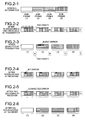
- Figs. 2-1 to 2-6 are explanatory diagrams of a flow of transmission and reception processes in the error correction optical communication system. Specifically, the flow includes the encoding of a transmission information frame, and the reproduction of the reception information frame from the reception signal.
- Fig. 2-1 depicts one example of a transmission information frame.
- one transmission information frame is divided into four sub-frames (1) to (4).
- Fig. 2-2 depicts a bit string after the interleaver 11 and the FEC encoder 12 of the transmitter 1 carried out the process.
- the interleaver 11 divides each sub-frame into four pieces, and arranges the divided pieces in the order of the sub-frames (1) to (4).
- the FEC parities, corresponding to A, B, C, and D in Fig. 2-2 are added respectively to the four-piece blocks after the interleaving operation is carried out.
- One four-piece block and an FEC parity added thereto constitute one codeword.
- the transmission signal (corresponding to the output of the selector 14) is transmitted in a state that the FEC parities are inserted into the four non-interleaved sub-frames.
- Fig. 2-3 depicts the output of the selector 21 of the receiver 2.
- the selector 21 selectively outputs the sub-frame part (corresponding to the information frame part) and the FEC parity part.
- Fig. 2-4 depicts a state that the interleaver 22 of the receiver 2 changes the order of the bits. The order of the bits is changed based on the same rule as that used at the transmission side, and the burst error that has occurred in the sub-frame (2) is allocated to four different codewords.
- Fig. 2-5 depicts a state that the FEC decoder 23 has corrected all the errors. For example, even when a burst error that cannot be corrected straight has occurred as shown in Fig. 2-3 , the interleaver 22 can correct the burst error by allocating the error to plural codewords.
- Fig. 2-6 depicts a state that the de-interleaver 24 has reproduced original sub-frames (1) to (4).
- the transmission information frame is sufficiently longer than the error correction codewords and those plural sub-frames can be interleaved.
- the method of interleaving is not limited to that described above, and the positions of the bits of the information frame can be rearranged based on any rule.
- the communication apparatus at the transmission side generates the FEC parities using the interleaver and the FEC encoder, and inserts the FEC parities into the transmission information frame and sends this frame.
- the communication apparatus at the reception side extracts the error information frame and the FEC parities from the received signal.
- the interleaver rearranges the order of bits of the extracted information frame based on the same rule as that used at the transmission side.
- the FEC decoder corrects the information frame whose bit positions are rearranged, using the extracted FEC parities.
- the de-interleaver rearranges the bits of the error-corrected reception information frame, based on the rule opposite to the used above.
- the frame obtained as a result of rearranging the bits is output as the reproduced reception information frame. Consequently, a burst error can be corrected satisfactorily, without requiring the communication apparatus at the transmission side to send the interleaved signal.
- the error correction optical communication system according to the second embodiment has the same configuration as that of the error correction optical communication system according to the first embodiment shown in Fig. 1 .
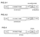
- Figs. 3-1 and 3-2 depict an example of an Ethernet (registered trademark) frame which is made an FEC frame (codeword).
- the Ethernet (registered trademark) frame corresponds to the above transmission information frame.
- the Ethernet (registered trademark) frame is prescribed by the "IEEE Std 802.3ah" as Non-Patent Document 1.
- Fig. 3-1 depicts that all areas other than the FEC parity are to be interleaved
- Fig. 3-2 depicts that only the Ethernet (registered trademark) frame is to be interleaved.
- S_FEC denotes a marker that expresses the head of the FEC frame
- T_FEC denotes a marker that expresses the tail of the FEC frame.
- the whole frames shown in Figs. 3-1 and 3-2 correspond to one codeword, i.e., correspond to one of the four codewords shown in Fig. 2-2 .
- a byte of eight bits that constitute the FEC frame and a byte as one unit of the 8B-to-10B conversion are byte-synchronized so that the header bits of these bytes coincide with each other.
- propagation of a bit error that has occurred in the transmission path to plural bytes of the FEC frames can be prevented.
- an original Ethernet (registered trademark) frame the Ethernet (registered trademark) frame before dividing
- the area which is short is filled with dummy bits by a virtual calculation of the FEC parity.
- the dummy bits are virtual, and are not actually present in the serial bit string to be transmitted to the transmission path.
- the Ethernet (registered trademark) frame when the Ethernet (registered trademark) frame is to be applied to the error correction optical communication system, it is made an FEC frame (codeword) as shown in Figs. 3-1 and 3-2 .
- the Ethernet (registered trademark) frame is divided into plural sub-frames, and the plural sub-frames are interleaved as described above. Based on this arrangement, the same effect as that achieved in the first embodiment can be also achieved in the system using the Ethernet (registered trademark) frame.
- the error correction optical communication system according to the third embodiment has the same configuration as that of the error correction optical communication system according to the first embodiment shown in Fig. 1 .
- the Ethernet (registered trademark) frame that is made an FEC frame (codeword) is explained like in the second embodiment.
- the Reed-Solomon (255, 239) is used as the FEC, thereby achieving excellent error correction capacity.
- Fig. 4 depicts one example in which the Ethernet (registered trademark) frame is made an FEC frame (codeword).
- 239 bytes include the Ethernet (registered trademark) frame, S_FEC, and T_FEC, and 16 bytes include the FEC parity.
- one codeword (corresponding to four codewords shown in Fig. 2-2 ) is formed in the total 255 bytes.
- the Ethernet (registered trademark) frame is divided into sub-frames, and plural sub-frames are interleaved (as shown in Figs. 2-1 and 2-2 ), thereby generating the FEC parities, in a similar manner to that described above.
- the Reed-Solomon codes having a high error correction capacity are used as the FEC to the error correction optical communication system shown in the first embodiment. Based on this arrangement, the same effect as that achieved in the first and the second embodiments can be also achieved, and a general-purpose system can be obtained.
- an error correction optical communication system is explained below.
- the error correction optical communication system can achieve a similar effect to that of the above embodiments, even in a case in which one transmission information frame is short, and thus a satisfactory burst error correction effect cannot be achieved when the transmission information frame is interleaved as a single frame. This is explained below.
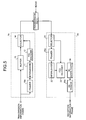
- Fig. 5 is a configuration diagram of the error correction optical communication system according to the fourth embodiment of the present invention.
- the error correction optical communication system according to the fourth embodiment includes a transmitter 1a as a communication apparatus at a transmission side, and a receiver 2a as a communication apparatus at a reception side.
- the transmitter 1a includes a framer (FRAMER) 15a, in addition to the configuration of the first embodiment.
- the receiver 2a includes a framer (FRAMER) 25a, and a de-framer (DE-FRAMER) 26a, in addition to the configuration of the first embodiment. Configurations similar to those explained in the first to the third embodiments are not explained herein.
- a frame sufficiently longer than the codeword is formed by combining plural transmission information frames as in the above embodiments.
- the burst error is corrected using this long frame.
- the framers 15a and 25a generate one frame by combining plural short transmission frames.
- the de-framer 26a disassembles the bit string, which is de-interleaved by the de-interleaver 24 in advance, into original short transmission information frames, thereby generating the reception information frame.
- Figs. 6-1 to 6-8 are explanatory diagrams of a flow of transmission and reception processes in the error correction optical communication system according to the fourth embodiment. Specifically, the flow includes the encoding of a transmission information frame, and the reproduction of the reception information frame from the reception signal.
- Fig. 6-1 depicts one example of a transmission information frame.
- each of transmission information frames (1) to (4) (shown by "Information" in Fig. 6-1 ) has only the length approximately the same as that of a codeword that constitutes an error correction code.
- Fig. 6-2 depicts an output of the framer 15a that combines the four transmission information frames to compose one frame.
- Fig. 6-3 depicts a bit string after the interleaver 11 and the FEC encoder 12 of the transmitter 1a carry out the process.
- the interleaver 11 divides the frame generated by the framer 15a, into four pieces, and arranges the divided pieces in the order of (1) to (4).
- the transmission signal (corresponding to the output of the selector 14) is transmitted in the state that the FEC parities are inserted into the four non-interleaved transmission information frames.
- Fig. 6-4 depicts the output of the selector 21 of the receiver 2a.
- a state that a burst error has occurred in the information frame (2) due to a noise on the transmission path is shown.
- the selector 21 selectively outputs the information frame part and the FEC parity part.
- Fig. 6-5 depicts a state that the interleaver 22 of the receiver 2a changes the order of the bits. The order of the bits is changed based on the same rule as that used at the transmission side, and the burst error that has occurred in the information frame (2) is allocated to four different codewords.
- Fig. 6-6 depicts a state that the FEC decoder 23 has corrected all the errors. For example, even when a burst error that cannot be corrected straight has occurred as shown in Fig. 6-4 , the interleaver 22 can correct the burst error by allocating the error into plural codewords.
- Fig. 6-7 depicts a state that the de-interleaver 24 has reproduced the original frame by combining the four transmission information frames.
- Fig. 6-8 depicts a state that the de-framer 26a divides the frame shown in Fig. 6-7 , thereby generating the reception information frame.
- the fourth embodiment even in a case in which one transmission information frame is short, and thus a satisfactory burst error correction effect cannot be achieved when the transmission information frame is interleaved as a single frame, with the framers 15a, 25a and the de-framer 26a, it is possible to interleave the frame as plural transmission information frames. Accordingly, when a burst error as shown in Fig. 6-4 occurs, the burst error can be corrected satisfactorily, like in the above embodiments.
- Fig. 7 is a configuration example of the error correction optical communication system according to the fifth embodiment.
- the error correction optical communication system according to the fifth embodiment includes a transmitter 1b as a communication apparatus at the transmission side, and a receiver 2b as a communication apparatus at the reception side.
- the transmitter 1b includes an outer-code FEC encoder (OUTER-ENCODER) 16, an interleaver (INTERLEAVER) 17, and an inner-code FEC encoder (INNER-ENCODER) 18, in addition to the configuration of the first embodiment.
- the receiver 2b includes adders 27 and 29, an interleaver (INTERLEAVER) 28, an inner-code FEC decoder (INNER-DECODER) 30, a de-interleaver (DE-INTERLEAVER), and an outer-code FEC decoder (OUTER-DECODER) 32, in addition to the configuration of the first embodiment.
- communications are carried out in one direction from the transmitter 1b to the receiver 2b to simplify the explanation.
- each communication apparatus has both functions of a transmitter and a receiver, and can achieve communications in both directions.
- the transmitter 1b first branches a received transmission information frame into two paths.
- the interleaver 11 as a first interleaver changes the order of the bits that constitute the transmission information frame, based on a predetermined rule, and the outer-code FEC encoder 16 carries out an error correction encoding, thereby generating an FEC parity of an outer code.
- the interleaver 17 as a second interleaver changes the order of the bits that constitute the output (a transmission information frame that is error-correction-encoded after the interleaving) of the outer-code FEC encoder 16, based on a predetermined rule, and the inner-code FEC encoder 18 carries out an error correction encoding, thereby generating an FEC parity of an inner code.
- the buffer 13 adds a delay to the transmission information frame for the time period required to carry out the interleave and the error correction (the time required for the process carried out by the interleaver 27 to the inner-code FEC encoder 30).
- the selector 14 adds the above-generated FEC parity of the outer code and FEC parity of the inner code, to a predetermined position of the transmission information frame received via the buffer 13, thereby generating a transmission signal.
- the receiver 2b receives the transmission signal that is affected by noise in the transmission path.
- the selector 21 divides the received signal into an information frame part, an FEC parity part of the outer code, and an FEC parity part of the inner code.
- the interleaver 22 as a third interleaver changes the order of bits of the information frame part in the same order as the first interleave carried out by the interleaver 11 at the transmitter 1b side.
- the adder 27 adds the FEC parity of the outer code (the FEC parity of the outer code allocated by the selector 21).
- the interleaver 28 as a fourth interleaver changes the order of bits of the information frame part in the same order as the second interleave carried out by the interleaver 18 at the transmitter 1b side.
- the adder 29 adds the FEC parity of the inner code (the FEC parity of the inner code allocated by the selector 21).
- the inner-code FEC decoder 30 carries out the error correction using the FEC parity of the inner code.
- the de-interleaver 31 changes the order of bits of the information frame part in a rule opposite to that of the interleaver 17 (a rule to return the bits after the interleaving to a state before the interleaving).
- the outer-code FEC decoder 32 carries out an error correction using the FEC parity of the outer code.
- the de-interleaver 24 returns the order of the bits of the error-corrected information frame to the original order in a rule opposite to that of the interleaver 11, and outputs the bits as a reception information frame.
- Plural transmission information frames can be used in combination, like in the fourth embodiment.
- the framer 15a shown in the fourth embodiment is added to the pre-stage of the interleaver 11 of the transmitter 1b.
- the transmitter 1b carries out the above-described FEC parity generation process, using the frame generated by the framer 15a (the frame generated by combining plural transmission information frames), thereby generating the FEC parity of the outer code and the FEC parity of the inner code.
- the framer 25a and the de-flamer 26a shown in the fourth embodiment are added to the post-stage of the selector 21 and the de-interleaver 24 of the receiver 2b, respectively.
- the receiver 2b executes the above-described reproduction process of a reception information frame using the frame generated by the framer 25a, thereby reproducing the frame generated by the framer 15a.
- the de-flamer 26a divides the reproduced frame to generate a reception information frame.
- the fifth embodiment is a concrete example of the application of the methods explained in the first to the fourth embodiments to the junction codes.
- the communication apparatus at the transmission side generates two FEC parities using two interleavers and two FEC encoders, and inserts the FEC parities into the transmission information frame and sends this frame.
- the communication apparatus at the reception side extracts the error information frame and the two FEC parities from the received signal.
- the two interleavers rearrange the order of bits of the extracted information frame based on the same rule as that used at the transmission side.
- the two FEC decoders correct the information frame whose bit positions are rearranged, using the extracted FEC parities.
- the two de-interleavers rearrange the bits of the error-corrected reception information frame, based on the rule opposite to that used above.
- the frame obtained as a result of rearranging the bits is output as the reproduced reception information frame. Consequently, a burst error can be corrected satisfactorily, without requiring the communication apparatus at the transmission side to send the interleaved signal.
- error correction optical communication system includes two junction codes of an outer code and an inner code
- this system can also include three or more codewords.
- the communication apparatus, the transmitter, and the receiver, according to the present invention are useful for an error correction optical communication system having an error correction (FEC) function, and particularly is suitable as a communication apparatus that transmits and receives a non-interleaved information frame and corrects an error of the information frame.
- FEC error correction
Landscapes
- Engineering & Computer Science (AREA)
- Physics & Mathematics (AREA)
- Probability & Statistics with Applications (AREA)
- Theoretical Computer Science (AREA)
- Computer Networks & Wireless Communication (AREA)
- Signal Processing (AREA)
- Mathematical Physics (AREA)
- Algebra (AREA)
- General Physics & Mathematics (AREA)
- Pure & Applied Mathematics (AREA)
- Error Detection And Correction (AREA)
- Detection And Prevention Of Errors In Transmission (AREA)
Abstract
A communication apparatus according to the present invention includes a transmitting unit and a receiving unit. The transmitting unit includes an interleaver 11 that rearranges positions of bits of an information frame, an FEC encoder 12 that carries out an error correction encoding to the information frame of which bit positions are rearranged, and a selector 14 that inserts FEC parities into predetermined positions of the information frame, thereby generating a transmission signal. The receiving unit includes a selector 21 that extracts an information frame part and an FEC parity part from a reception signal, an interleaver 22 that rearranges positions of the bits of the information frame part based on the same rule as that of the transmission side, an FEC decoder 23 that corrects an error of bits, which has been rearranged, based on the error correction parity part, and a de-interleaver 24 that reproduces an information frame by returning positions of error-corrected bits to original bit positions.
Description
- The present invention relates to an error correction optical communication system having an error correction (FEC) function, and, more particularly to an error correction optical communication system that transmits and receives a non-interleaved information frame.
- An optical access system, a so-called "Fiber To The Home (FTTH)", that transmits large-capacity information to houses and offices, is being distributed rapidly. Among others, the service of "Gigabit Ethernet (registered trademark) PON (normally known as GE-PON)" that uses a "Passive Optical Network (PON)" system is being spread rapidly as a method of connecting Gigabit Ethernet (registered trademark) between a telecommunications house and plural users, since specifications are standardized in Non-Patent
Document 1 listed below. - The GE-PON has a configuration that an "Optical Line Terminal (OLT)" as a station-side device and an "Optical Network Unit (ONU)" as a user-side device are connected in two directions with one optical fiber via an optical branch unit. A point-to-multipoint connection, for example, a connection between one OLT and 32 ONUs, is made possible by carrying out a burst transmission and reception in which a time slot is shared among users.
- According to the GE-PON, the optical branch unit braches power. Therefore, the optical power that each ONU receives is attenuated to one to the number of branches, and light that the OLT receives from each ONU is also attenuated to one to the number of branches. Consequently, a bit error is likely to occur. Furthermore, the fact that a laser diode having low performance is being used to decrease the cost is also likely to cause this bit error problem. To solve these problems, each of the OLT and the ONU is equipped with the error correction (Forward Error Correction: FEC) function, and a system of correcting bit errors whose amount is smaller than that the FEC can correct is standardized in Non-Patent
Document 1 listed below. - The FEC prescribed by Non-Patent
Document 1 is Reed-Solomon (255, 239). According to this FEC, 16-byte error correction symbols (hereinafter, "FEC parity") are added to 239-byte information data symbols, thereby structuring a block of "239+16=255" bytes. When the Ethernet (registered trademark) data is smaller than 239 bytes, "zeros" are filled in the data to satisfy 239 bytes. A starting sequence and an ending sequence are added before and after the FEC parity to be added. When the system does not use the FEC, the added FEC parity is disregarded, thereby carrying out communications without changing the conventional device. - The Reed-Solomon (255, 239) error correction system has a capacity to be able to correct up to octuple byte errors. In other words, the Reed-Solomon (255, 239) error correction system can correct all bit errors when the error is within eight bytes among 255 bytes. However, when a bit error occurs extending to nine bytes, the Reed-Solomon (255, 239) cannot correct the error. In a transmission path of actual optical communications, bit errors occur continuously in some cases, due to a fluctuation of polarization, non-linearity of an optical fiber, or insufficient performance of a transmitter/receiver. Even when the total number of bit errors that occur during a predetermined time is equal to or smaller than the number of bit errors that the Reed-Solomon (255, 239) can correct, the errors cannot be corrected when these bit errors are burst errors that occur during a short period of time. To solve this problem, there is a method of randomizing the occurrence of bit errors so that the bit errors do not occur in burst. This method is disclosed in
Non-Patent Document 2, for example. - According to the FEC system disclosed in Non-Patent
Document 2 listed below, an FEC encoder adds the FEC parity to a transmission information frame, and thereafter, an interleaver changes the order of bits, at the transmission side. On the other hand, at the reception side, a process opposite to that carried out at the transmission side is carried out. In other words, a de-interleaver and an FEC decoder are used to reproduce the transmission information frame. According to Non-PatentDocument 2, the bit order is changed within 16 codewords. For example, when a continuous burst error of 512 bits occurs in a transmission path, 16 codewords are returned to an original bit string in a de-interleaver at the reception side, and the error is input as a continuous error of 32 bits (obtained by 512/16), to the FEC decoder. In this case, the continuous 32 bits become equal to or smaller than five bytes. Therefore, the Reed-Solomon (255, 239) error correction system can correct all errors. - Non-Patent Document 1: IEEE Std 802.3ah
Non-Patent Document 2: ITU-T Recommendation G.975 - In
Non-Patent Document 1, the standard GE-PON device has both systems using the FEC and the system not using the FEC. Therefore, an interleave operation of the Ethernet (registered trademark) data series is not carried out. This is because when the interleave of the Ethernet (registered trademark) data series is carried out, a system that does not have a de-interleaver (not using the FEC) at the reception side cannot receive the data. Therefore, according to the Reed-Solomon (255, 239) that does not carry out interleaving of the Ethernet (registered trademark) data series, even when one bit error occurs for each nine bytes within one block in the Reed-Solomon (255, 239), this block cannot be corrected in the worst case. Consequently, the Ethernet (registered trademark) packet is discarded by an Ethernet (registered trademark) frame check sequence. In other words, the burst error tolerance is considerably low. - On the other hand, systems called a junction code and a product code, each constituted by two or more codewords, are known as a method of increasing the error correction capacity. However, each codeword needs to be interleaved, and there arises a problem that a decoding cannot be achieved correctly by merely disregarding an added FEC parity.
- The present invention is achieved in view of the above, and it is an object of the present invention to provide a communication apparatus and an error correction optical communication system capable of correcting a burst error satisfactorily without requiring a communication apparatus at a transmission side to send an interleaved signal.
- To solve the above problems and achieve the object, the communication apparatus according to the present invention includes a transmitting unit and a receiving unit each of which has an error correction function, and transmits and receives an information frame sufficiently longer than a codeword, wherein the transmitting unit includes a first interleaver that rearranges positions of bits in an information frame based on a predetermined rule; an error correction encoder that carries out an error correction encoding to the information frame whose bit positions have been rearranged; and a transmission signal generator that inserts error correction parities obtained by the encoding operation into predetermined positions of the information frame, thereby generating a transmission signal, and the receiving unit includes a reception signal extractor that extracts a part corresponding to the information frame and a part corresponding to the error correction parities, from a reception signal; a second interleaver that rearranges the information frame part based on the same rule as that of the first interleaver; a decoder that corrects an error of bits rearranged by the second interleaver, based on the error correction parity part; and a de-interleaver that reproduces an information frame by returning positions of the error-corrected bits to original bit positions.
- According to the present invention, a burst error can be corrected satisfactorily, without requiring a communication apparatus at a transmission side to send an interleaved signal.
- Moreover, improvement of the error correction capacity by a junction code or a product code can be expected.
-
- [
Fig. 1] Fig. 1 is a configuration example of an error correction optical communication system according to the present invention. - [
Fig. 2-1] Fig. 2-1 is an explanatory diagram of a flow of transmission and reception processes in the error correction optical communication system. - [
Fig. 2-2] Fig. 2-2 is an explanatory diagram of a flow of transmission and reception processes in the error correction optical communication system. - [
Fig. 2-3] Fig. 2-3 is an explanatory diagram of a flow of transmission and reception processes in the error correction optical communication system. - [
Fig. 2-4] Fig. 2-4 is an explanatory diagram of a flow of transmission and reception processes in the error correction optical communication system. - [
Fig. 2-5] Fig. 2-5 is an explanatory diagram of a flow of transmission and reception processes in the error correction optical communication system. - [
Fig. 2-6] Fig. 2-6 is an explanatory diagram of a flow of transmission and reception processes in the error correction optical communication system. - [
Fig. 3-1] Fig. 3-1 is one example of an Ethernet (registered trademark) frame which is made an FEC frame. - [
Fig. 3-2] Fig. 3-2 is another example of an Ethernet (registered trademark) frame which is made an FEC frame. - [
Fig. 4] Fig. 4 is still another example of an Ethernet (registered trademark) frame which is made an FEC frame. - [
Fig. 5] Fig. 5 is a configuration example of the error correction optical communication system according to the present invention. - [
Fig. 6-1] Fig. 6-1 is an explanatory diagram of a flow of transmission and reception processes in the error correction optical communication system. - [
Fig. 6-2] Fig. 6-2 is an explanatory diagram of a flow of transmission and reception processes in the error correction optical communication system. - [
Fig. 6-3] Fig. 6-3 is an explanatory diagram of a flow of transmission and reception processes in the error correction optical communication system. - [
Fig. 6-4] Fig. 6-4 is an explanatory diagram of a flow of transmission and reception processes in the error correction optical communication system. - [
Fig. 6-5] Fig. 6-5 is an explanatory diagram of a flow of transmission and reception processes in the error correction optical communication system. - [
Fig. 6-6] Fig. 6-6 is an explanatory diagram of a flow of transmission and reception processes in the error correction optical communication system. - [
Fig. 6-7] Fig. 6-7 is an explanatory diagram of a flow of transmission and reception processes in the error correction optical communication system. - [
Fig. 6-8] Fig. 6-8 is an explanatory diagram of a flow of transmission and reception processes in the error correction optical communication system. - [
Fig. 7] Fig. 7 is a configuration example of an error correction optical communication system according to the present invention. -
- 1, 1a, 1b transmitter
- 2, 2a, 2b receiver
- 11, 17 interleaver (INTERLEAVER)
- 12 FEC encoder (FEC ENCODER)
- 13 buffer (BUFFER)
- 14 selector (SELECTOR)
- 15a framer (FRAMER)
- 16 outer-code FEC encoder (OUTER-ENCODER)
- 18 inner-code FEC encoder (INNER-ENCODER)
- 21 selector (SELECTOR)
- 22, 28 interleaver (INTERLEAVER)
- 23 FEC decoder (FEC DECODER)
- 24, 31 de-interleaver (DE-INTERLEAVER)
- 25a framer (FRAMER)
- 26a de-framer (DE-FRAMER)
- 27, 29 adder
- 30 inner-code FEC decoder (INNER-DECODER)
- 32 outer-code FEC decoder (OUTER-DECODER)
- Exemplary embodiments according to the present invention are explained below in detail with reference to the accompanying drawings. Note that the invention is not limited to the embodiments.
-
Fig. 1 is a configuration example of an error correction optical communication system according to the present invention. The error correction optical communication system includes atransmitter 1 as a communication apparatus at a transmission side, and areceiver 2 as a communication apparatus at a reception side. Thetransmitter 1 includes an interleaver (INTERLEAVER) 11, and an FEC encoder (FEC ENCODER) 12, a buffer (BUFFER) 13, and a selector (SELECTOR) 14. Thereceiver 2 includes a selector (SELECTOR) 21, an interleaver (INTERLEAVER) 22, an FEC decoder (FEC DECODER) 23, and a de-interleaver (DE-INTERLEAVER) 24. In the first embodiment, communications are carried out in one direction from thetransmitter 1 to thereceiver 2 to simplify the explanation. However, in the actual system, each communication apparatus has both a transmitter and a receiver, and can achieve communications in both directions. - In
Fig. 1 , thetransmitter 1 branches a received transmission information frame into two. In one path, theinterleaver 11 changes the order of the bits that constitute the transmission information frame, based on a predetermined rule, and theFEC encoder 12 carries out an error correction encoding, thereby generating an FEC parity. In the other path, thebuffer 13 adds a delay to the transmission information frame for the time period required to carry out the interleave and the error correction. Theselector 14 adds the FEC parity to a predetermined position of the transmission information frame received via thebuffer 13, thereby generating a transmission signal. - On the other hand, the
receiver 2 receives the transmission signal that receives the influence of noise in the transmission path. Theselector 21 divides the received signal into an information frame part and an FEC parity part. Theinterleaver 22 changes the order of bits of the information frame part in the same order as that carried out by theinterleaver 11 at thetransmitter 1 side. Furthermore, theFEC decoder 23 carries out the error correction using the FEC parity extracted in theselector 21. Thereafter, the de-interleaver 24 returns the order of the bits of the error-corrected information frame to the original order. Finally, thede-interleaver 24 of thereceiver 2 outputs the bits whose positions have been rearranged, as a reception information frame. - The operation of the error correction optical communication system is explained in detail below with reference to the drawings.
Figs. 2-1 to 2-6 are explanatory diagrams of a flow of transmission and reception processes in the error correction optical communication system. Specifically, the flow includes the encoding of a transmission information frame, and the reproduction of the reception information frame from the reception signal. -
Fig. 2-1 depicts one example of a transmission information frame. In this example, one transmission information frame is divided into four sub-frames (1) to (4).Fig. 2-2 depicts a bit string after theinterleaver 11 and theFEC encoder 12 of thetransmitter 1 carried out the process. Theinterleaver 11 divides each sub-frame into four pieces, and arranges the divided pieces in the order of the sub-frames (1) to (4). The FEC parities, corresponding to A, B, C, and D inFig. 2-2 , are added respectively to the four-piece blocks after the interleaving operation is carried out. One four-piece block and an FEC parity added thereto constitute one codeword. On the transmission path, the transmission signal (corresponding to the output of the selector 14) is transmitted in a state that the FEC parities are inserted into the four non-interleaved sub-frames. -
Fig. 2-3 depicts the output of theselector 21 of thereceiver 2. A state that a burst error has occurred in the sub-frame (2) due to a noise on the transmission path is shown. Theselector 21 selectively outputs the sub-frame part (corresponding to the information frame part) and the FEC parity part.Fig. 2-4 depicts a state that theinterleaver 22 of thereceiver 2 changes the order of the bits. The order of the bits is changed based on the same rule as that used at the transmission side, and the burst error that has occurred in the sub-frame (2) is allocated to four different codewords. -
Fig. 2-5 depicts a state that theFEC decoder 23 has corrected all the errors. For example, even when a burst error that cannot be corrected straight has occurred as shown inFig. 2-3 , theinterleaver 22 can correct the burst error by allocating the error to plural codewords.Fig. 2-6 depicts a state that the de-interleaver 24 has reproduced original sub-frames (1) to (4). - In the error correction optical communication system according to the first embodiment, it is important that the transmission information frame is sufficiently longer than the error correction codewords and those plural sub-frames can be interleaved. The method of interleaving is not limited to that described above, and the positions of the bits of the information frame can be rearranged based on any rule.
- As explained above, according to the first embodiment, the communication apparatus at the transmission side generates the FEC parities using the interleaver and the FEC encoder, and inserts the FEC parities into the transmission information frame and sends this frame. The communication apparatus at the reception side extracts the error information frame and the FEC parities from the received signal. Furthermore, the interleaver rearranges the order of bits of the extracted information frame based on the same rule as that used at the transmission side. The FEC decoder corrects the information frame whose bit positions are rearranged, using the extracted FEC parities. Finally, the de-interleaver rearranges the bits of the error-corrected reception information frame, based on the rule opposite to the used above. The frame obtained as a result of rearranging the bits is output as the reproduced reception information frame. Consequently, a burst error can be corrected satisfactorily, without requiring the communication apparatus at the transmission side to send the interleaved signal.
- An error correction optical communication system according to a second embodiment is explained below. The error correction optical communication system according to the second embodiment has the same configuration as that of the error correction optical communication system according to the first embodiment shown in
Fig. 1 . -
Figs. 3-1 and 3-2 depict an example of an Ethernet (registered trademark) frame which is made an FEC frame (codeword). In this case, the Ethernet (registered trademark) frame corresponds to the above transmission information frame. The Ethernet (registered trademark) frame is prescribed by the "IEEE Std 802.3ah" asNon-Patent Document 1. - Specifically,
Fig. 3-1 depicts that all areas other than the FEC parity are to be interleaved, andFig. 3-2 depicts that only the Ethernet (registered trademark) frame is to be interleaved. InFigs. 3-1 and 3-2 , S_FEC denotes a marker that expresses the head of the FEC frame, and T_FEC denotes a marker that expresses the tail of the FEC frame. The whole frames shown inFigs. 3-1 and 3-2 correspond to one codeword, i.e., correspond to one of the four codewords shown inFig. 2-2 . The FEC frames shown inFig. 3-1, Fig. 3-2, and Fig. 4 are 8B-to-10B converted in the transmission path. A byte of eight bits that constitute the FEC frame and a byte as one unit of the 8B-to-10B conversion are byte-synchronized so that the header bits of these bytes coincide with each other. By carrying out the byte-synchronization, propagation of a bit error that has occurred in the transmission path to plural bytes of the FEC frames can be prevented. When an original Ethernet (registered trademark) frame (the Ethernet (registered trademark) frame before dividing) is not sufficiently longer than the codeword, the area which is short is filled with dummy bits by a virtual calculation of the FEC parity. The dummy bits are virtual, and are not actually present in the serial bit string to be transmitted to the transmission path. - As explained above, according to the second embodiment, for example, when the Ethernet (registered trademark) frame is to be applied to the error correction optical communication system, it is made an FEC frame (codeword) as shown in
Figs. 3-1 and 3-2 . In other words, the Ethernet (registered trademark) frame is divided into plural sub-frames, and the plural sub-frames are interleaved as described above. Based on this arrangement, the same effect as that achieved in the first embodiment can be also achieved in the system using the Ethernet (registered trademark) frame. - An error correction optical communication system according to a third embodiment is explained below. The error correction optical communication system according to the third embodiment has the same configuration as that of the error correction optical communication system according to the first embodiment shown in
Fig. 1 . In the third embodiment, the Ethernet (registered trademark) frame that is made an FEC frame (codeword) is explained like in the second embodiment. - In the third embodiment, the Reed-Solomon (255, 239) is used as the FEC, thereby achieving excellent error correction capacity.
Fig. 4 depicts one example in which the Ethernet (registered trademark) frame is made an FEC frame (codeword). In this example, 239 bytes include the Ethernet (registered trademark) frame, S_FEC, and T_FEC, and 16 bytes include the FEC parity. Accordingly, one codeword (corresponding to four codewords shown inFig. 2-2 ) is formed in the total 255 bytes. In the third embodiment, the Ethernet (registered trademark) frame is divided into sub-frames, and plural sub-frames are interleaved (as shown inFigs. 2-1 and 2-2 ), thereby generating the FEC parities, in a similar manner to that described above. - As explained above, in the third embodiment, for example, the Reed-Solomon codes having a high error correction capacity are used as the FEC to the error correction optical communication system shown in the first embodiment. Based on this arrangement, the same effect as that achieved in the first and the second embodiments can be also achieved, and a general-purpose system can be obtained.
- An error correction optical communication system according to a fourth embodiment is explained below. In the fourth embodiment, the error correction optical communication system can achieve a similar effect to that of the above embodiments, even in a case in which one transmission information frame is short, and thus a satisfactory burst error correction effect cannot be achieved when the transmission information frame is interleaved as a single frame. This is explained below.
-
Fig. 5 is a configuration diagram of the error correction optical communication system according to the fourth embodiment of the present invention. The error correction optical communication system according to the fourth embodiment includes atransmitter 1a as a communication apparatus at a transmission side, and areceiver 2a as a communication apparatus at a reception side. Thetransmitter 1a includes a framer (FRAMER) 15a, in addition to the configuration of the first embodiment. Thereceiver 2a includes a framer (FRAMER) 25a, and a de-framer (DE-FRAMER) 26a, in addition to the configuration of the first embodiment. Configurations similar to those explained in the first to the third embodiments are not explained herein. - For example, in the fourth embodiment, even in a case in which one transmission information frame is short, and a satisfactory burst error correction effect cannot be achieved when the transmission information frame is interleaved as a single frame, a frame sufficiently longer than the codeword is formed by combining plural transmission information frames as in the above embodiments. The burst error is corrected using this long frame. Specifically, in
Fig. 5 , for example, theframers - The operation of the error correction optical communication system according to the fourth embodiment is explained in detail below referring to drawings.
Figs. 6-1 to 6-8 are explanatory diagrams of a flow of transmission and reception processes in the error correction optical communication system according to the fourth embodiment. Specifically, the flow includes the encoding of a transmission information frame, and the reproduction of the reception information frame from the reception signal. -
Fig. 6-1 depicts one example of a transmission information frame. In this example, each of transmission information frames (1) to (4) (shown by "Information" inFig. 6-1 ) has only the length approximately the same as that of a codeword that constitutes an error correction code.Fig. 6-2 depicts an output of theframer 15a that combines the four transmission information frames to compose one frame.Fig. 6-3 depicts a bit string after theinterleaver 11 and theFEC encoder 12 of thetransmitter 1a carry out the process. Theinterleaver 11 divides the frame generated by theframer 15a, into four pieces, and arranges the divided pieces in the order of (1) to (4). The FEC parities, corresponding to A, B, C, and D inFig. 6-1 , are added respectively to the four-piece blocks after the interleaving operation is carried out. One four-piece blocks and a corresponding FEC parity constitute one codeword. On the transmission path, the transmission signal (corresponding to the output of the selector 14) is transmitted in the state that the FEC parities are inserted into the four non-interleaved transmission information frames. -
Fig. 6-4 depicts the output of theselector 21 of thereceiver 2a. A state that a burst error has occurred in the information frame (2) due to a noise on the transmission path is shown. Theselector 21 selectively outputs the information frame part and the FEC parity part.Fig. 6-5 depicts a state that theinterleaver 22 of thereceiver 2a changes the order of the bits. The order of the bits is changed based on the same rule as that used at the transmission side, and the burst error that has occurred in the information frame (2) is allocated to four different codewords. -
Fig. 6-6 depicts a state that theFEC decoder 23 has corrected all the errors. For example, even when a burst error that cannot be corrected straight has occurred as shown inFig. 6-4 , theinterleaver 22 can correct the burst error by allocating the error into plural codewords.Fig. 6-7 depicts a state that the de-interleaver 24 has reproduced the original frame by combining the four transmission information frames.Fig. 6-8 depicts a state that the de-framer 26a divides the frame shown inFig. 6-7 , thereby generating the reception information frame. - As explained above, according to the fourth embodiment, even in a case in which one transmission information frame is short, and thus a satisfactory burst error correction effect cannot be achieved when the transmission information frame is interleaved as a single frame, with the
framers Fig. 6-4 occurs, the burst error can be corrected satisfactorily, like in the above embodiments. - An error correction optical communication system according to a fifth embodiment of the present invention is explained next.
Fig. 7 is a configuration example of the error correction optical communication system according to the fifth embodiment. The error correction optical communication system according to the fifth embodiment includes a transmitter 1b as a communication apparatus at the transmission side, and areceiver 2b as a communication apparatus at the reception side. The transmitter 1b includes an outer-code FEC encoder (OUTER-ENCODER) 16, an interleaver (INTERLEAVER) 17, and an inner-code FEC encoder (INNER-ENCODER) 18, in addition to the configuration of the first embodiment. Thereceiver 2b includesadders receiver 2b to simplify the explanation. However, in the actual system, each communication apparatus has both functions of a transmitter and a receiver, and can achieve communications in both directions. - As shown in
Fig. 7 , the transmitter 1b first branches a received transmission information frame into two paths. In one path, theinterleaver 11 as a first interleaver changes the order of the bits that constitute the transmission information frame, based on a predetermined rule, and the outer-code FEC encoder 16 carries out an error correction encoding, thereby generating an FEC parity of an outer code. Theinterleaver 17 as a second interleaver changes the order of the bits that constitute the output (a transmission information frame that is error-correction-encoded after the interleaving) of the outer-code FEC encoder 16, based on a predetermined rule, and the inner-code FEC encoder 18 carries out an error correction encoding, thereby generating an FEC parity of an inner code. In the other path, thebuffer 13 adds a delay to the transmission information frame for the time period required to carry out the interleave and the error correction (the time required for the process carried out by theinterleaver 27 to the inner-code FEC encoder 30). Theselector 14 adds the above-generated FEC parity of the outer code and FEC parity of the inner code, to a predetermined position of the transmission information frame received via thebuffer 13, thereby generating a transmission signal. - On the other hand, the
receiver 2b receives the transmission signal that is affected by noise in the transmission path. Theselector 21 divides the received signal into an information frame part, an FEC parity part of the outer code, and an FEC parity part of the inner code. Theinterleaver 22 as a third interleaver changes the order of bits of the information frame part in the same order as the first interleave carried out by theinterleaver 11 at the transmitter 1b side. Further, theadder 27 adds the FEC parity of the outer code (the FEC parity of the outer code allocated by the selector 21). Further, theinterleaver 28 as a fourth interleaver changes the order of bits of the information frame part in the same order as the second interleave carried out by theinterleaver 18 at the transmitter 1b side. Further, theadder 29 adds the FEC parity of the inner code (the FEC parity of the inner code allocated by the selector 21). The inner-code FEC decoder 30 carries out the error correction using the FEC parity of the inner code. Thereafter, the de-interleaver 31 changes the order of bits of the information frame part in a rule opposite to that of the interleaver 17 (a rule to return the bits after the interleaving to a state before the interleaving). Further, the outer-code FEC decoder 32 carries out an error correction using the FEC parity of the outer code. Finally, the de-interleaver 24 returns the order of the bits of the error-corrected information frame to the original order in a rule opposite to that of theinterleaver 11, and outputs the bits as a reception information frame. - Plural transmission information frames can be used in combination, like in the fourth embodiment. Specifically, the
framer 15a shown in the fourth embodiment is added to the pre-stage of theinterleaver 11 of the transmitter 1b. The transmitter 1b carries out the above-described FEC parity generation process, using the frame generated by theframer 15a (the frame generated by combining plural transmission information frames), thereby generating the FEC parity of the outer code and the FEC parity of the inner code. Theframer 25a and the de-flamer 26a shown in the fourth embodiment are added to the post-stage of theselector 21 and the de-interleaver 24 of thereceiver 2b, respectively. Thereceiver 2b executes the above-described reproduction process of a reception information frame using the frame generated by theframer 25a, thereby reproducing the frame generated by theframer 15a. The de-flamer 26a divides the reproduced frame to generate a reception information frame. - As explained above, the fifth embodiment is a concrete example of the application of the methods explained in the first to the fourth embodiments to the junction codes. In other words, the communication apparatus at the transmission side generates two FEC parities using two interleavers and two FEC encoders, and inserts the FEC parities into the transmission information frame and sends this frame. The communication apparatus at the reception side extracts the error information frame and the two FEC parities from the received signal. Furthermore, the two interleavers rearrange the order of bits of the extracted information frame based on the same rule as that used at the transmission side. The two FEC decoders correct the information frame whose bit positions are rearranged, using the extracted FEC parities. Finally, the two de-interleavers rearrange the bits of the error-corrected reception information frame, based on the rule opposite to that used above. The frame obtained as a result of rearranging the bits is output as the reproduced reception information frame. Consequently, a burst error can be corrected satisfactorily, without requiring the communication apparatus at the transmission side to send the interleaved signal.
- While the error correction optical communication system according to the fifth embodiment includes two junction codes of an outer code and an inner code, this system can also include three or more codewords.
- When a product code including two or more codewords is used, similar effects can be obtained by carrying out interleaving and de-interleaving in a similar manner to that of the fifth embodiment.
- As descried above, the communication apparatus, the transmitter, and the receiver, according to the present invention are useful for an error correction optical communication system having an error correction (FEC) function, and particularly is suitable as a communication apparatus that transmits and receives a non-interleaved information frame and corrects an error of the information frame.
Claims (34)
- A communication apparatus that comprises a transmitting unit and a receiving unit each of which has an error correction function, and transmits and receives an information frame sufficiently longer than a codeword, wherein
the transmitting unit includes
a first interleaver that rearranges positions of bits in an information frame based on a predetermined rule;
an error correction encoder that carries out an error correction encoding to the information frame whose bit positions have been rearranged; and
a transmission signal generator that inserts error correction parities obtained by the encoding operation into predetermined positions of the information frame, thereby generating a transmission signal, and
the receiving unit includes
a reception signal extractor that extracts a part corresponding to the information frame and a part corresponding to the error correction parities, from a reception signal;
a second interleaver that rearranges the information frame part based on the same rule as that of the first interleaver;
a decoder that corrects an error of bits rearranged by the second interleaver, based on the error correction parity part; and
a de-interleaver that reproduces an information frame by returning positions of the error-corrected bits to original bit positions. - A communication apparatus that comprises a transmitting unit and a receiving unit each of which has an error correction function, and transmits and receives an information frame that is sufficiently short to an extent that a burst error cannot be corrected satisfactorily when the information frame is interleaved as a single information frame, wherein
the transmitting unit includes
a first frame generator that generates a frame sufficiently longer than a codeword, by combining a plurality of information frames;
a first interleaver that rearranges positions of bits in the frame generated by the first frame generator, based on a predetermined rule;
an error correction encoder that carries out an error correction encoding to the frame whose bit positions have been rearranged; and
a transmission signal generator that inserts error correction parities obtained by the encoding operation, into predetermined positions of the information frame, and
the receiving unit includes
a reception signal extractor that extracts a part corresponding to the information frame and a part corresponding to the error correction parities, from a reception signal;
a second frame generator that generates a frame sufficiently longer than a codeword, by combining a plurality of information frames;
a second interleaver that rearranges the frame generated by the second frame generator, based on the same rule as that used by the first interleaver;
a decoder that corrects an error of bits rearranged by the second interleaver, based on the error correction parity part;
a de-interleaver that returns positions of the error-corrected bits to original bit positions; and
a frame divider that divides the error-corrected frame obtained by the de-interleaver, into a plurality of original information frames. - The communication apparatus according to claim 1, wherein the information frame is an Ethernet (registered trademark) frame.
- The communication apparatus according to claim 2, wherein the information frame is an Ethernet (registered trademark) frame.
- The communication apparatus according to any one of claims 1 to 4, wherein a Reed-Solomon is used for carrying out the error correction encoding operation.
- A transmitter that transmits an information frame sufficiently longer than a codeword, the transmitter comprising:an interleaver that rearranges positions of bits in an information frame based on a predetermined rule;an error correction encoder that carries out an error correction encoding to the information frame whose bit positions have been rearranged; anda transmission signal generator that inserts error correction parities obtained by encoding into predetermined positions in the information frame, thereby generating a transmission signal.
- A transmitter that transmits an information frame that is sufficiently short to an extent that a burst error cannot be corrected satisfactorily when the information frame is interleaved as a single information frame, the transmitter comprising:a frame generator that generates a frame sufficiently longer than a codeword, by combining a plurality of information frames;an interleaver that rearranges positions of bits in the frame generated by the frame generator, based on a predetermined rule;an error correction encoder that carries out an error correction encoding to the frame whose bit positions have been rearranged; anda transmission signal generator that inserts error correction parities obtained by the encoding operation, into predetermined positions of the information frame.
- A receiver that has an error correction function, and receives an information frame sufficiently longer than a codeword, the receiver comprising:a reception signal extractor that extracts a part corresponding to an information frame and a part corresponding to an error correction parity, from a reception signal;an interleaver that rearranges the information frame part, based on the same rule as that used at a transmitter side;
a decoder that corrects an error of bits rearranged by the interleaver, based on the error correction parity part; anda de-interleaver that reproduces an information frame by returning positions of the error-corrected bits to original bit positions. - A receiver that has an error correction function, and receives an information frame that is sufficiently short to an extent that a burst error cannot be corrected satisfactorily when the information frame is interleaved as a single information frame, the receiver comprising:a reception signal extractor that extracts a part corresponding to an information frame and a part corresponding to an error correction parity, from a reception signal;a frame generator that generates a frame sufficiently longer than a codeword, by combining a plurality of information frames;an interleaver that rearranges the frame generated by the frame generator, based on the same rule as that used at a transmitter side;a decoder that corrects an error of bits rearranged by the interleaver, based on the error correction parity part;a de-interleaver that returns positions of the error-corrected bits to original bit positions; anda frame divider that divides the error-corrected frame obtained by the de-interleaver, into a plurality of original information frames.
- An error-correction optical communication system that has an error correction function, and transmits and receives an information frame sufficiently longer than a codeword, wherein
a communication apparatus at an information frame transmission side includes
a first interleaver that rearranges positions of bits in an information frame based on a predetermined rule;
an error correction encoder that carries out an error correction encoding to the information frame whose bit positions have been rearranged; and
a transmission signal generator that inserts error correction parities obtained by the encoding operation into predetermined positions of the information frame, thereby generating a transmission signal, and
a communication apparatus at an information frame reception side includes
a reception signal extractor that extracts a part corresponding to the information frame and a part corresponding to the error correction parities, from a reception signal;
a second interleaver that rearranges the information frame part based on the same rule as that of the first interleaver;
a decoder that corrects an error of bits rearranged by the second interleaver, based on the error correction parity part; and
a de-interleaver that reproduces an information frame by returning positions of the error-corrected bits to original bit positions. - An error-correction optical communication system that has an error correction function, and transmits and receives an information frame that is sufficiently short to an extent that a burst error cannot be corrected satisfactorily when the information frame is interleaved as a single transmission information frame, wherein
a communication apparatus at an information frame transmission side includesa first frame generator that generates a frame sufficiently longer than a codeword, by combining a plurality of information frames;a first interleaver that rearranges positions of bits in the frame generated by the first frame generator, based on a predetermined rule;an error correction encoder that carries out an error correction encoding to the frame whose bit positions have been rearranged; anda transmission signal generator that inserts error correction parities obtained by the encoding operation, into predetermined positions of the information frame, anda communication apparatus at an information frame reception side includesa reception signal extractor that extracts a part corresponding to the information frame and a part corresponding to the error correction parities, from a reception signal;a second frame generator that generates a frame sufficiently longer than a codeword, by combining a plurality of information frames;a second interleaver that rearranges in the frame generated by the second frame generator, based on the same rule as that used by the first interleaver;a decoder that corrects an error of bits rearranged by the second interleaver, based on the error correction parity part;a de-interleaver that returns positions of the error-corrected bits to original bit positions; anda frame divider that divides the error-corrected frame obtained by the de-interleaver, into a plurality of original information frames. - The error-correction optical communication system according to claim 10, wherein the information frame is an Ethernet (registered trademark) frame.
- The error-correction optical communication system according to claim 11, wherein the information frame is an Ethernet (registered trademark) frame.
- The error-correction optical communication system according to any one of claims 10 to 13, wherein a Reed-Solomon is used for carrying out the error correction encoding operation.
- A communication apparatus that comprises a transmitting unit and a receiving unit each of which has an error correction function, and transmits and receives an information frame sufficiently longer than a codeword, wherein
the transmitting unit includesa first interleaver that rearranges positions of bits in an information frame based on a predetermined rule;a first error correction encoder that carries out an error correction encoding using an outer code to the information frame whose bit positions have been rearranged;a second interleaver that rearranges bit positions of an output of the first error correction encoder based on a predetermined rule;a second error correction encoder that carries out an error correction encoding using an inner code to an output of the second interleaver; anda transmission signal generator that inserts a first error correction parity obtained by the first error correction encoding and a second error correction parity obtained by the second error correction encoding into predetermined positions of the information frame, thereby generating a transmission signal, andthe receiving unit includesa reception signal extractor that extracts a part corresponding to the information frame, a part corresponding to the first error correction parity, and a part corresponding to the second error correction parity, from a reception signal;a third interleaver that rearranges the information frame part based on the same rule as that of the first interleaver;a first adder that inserts the first error correction parity extracted by the reception signal extractor into signals rearranged by the third interleaver;a fourth interleaver that rearranges an output of the first adder based on the same rule as that of the second interleaver;a second adder that inserts the second error correction parity extracted by the reception signal extractor into signals rearranged by the fourth interleaver;a first decoder that corrects an error of an output of the second adder, using the second error correction parity included in the processed output;a first de-interleaver that rearranges signals of which error is corrected by the first decoder, in an order opposite to that of the rearrangement executed by the second interleaver;a second decoder that corrects an error of an output of the first de-interleaver, using the first error correction parity included in the processed output; and
a second de-interleaver that reproduces an information frame by returning positions of the error-corrected bits to original bit positions by rearranging signals of which error is corrected by an output of the second decoder, in an order opposite to that of the rearrangement executed by the first interleaver. - A communication apparatus that comprises a transmitting unit and a receiving unit each of which has an error correction function, and transmits and receives an information frame that is sufficiently short to an extent that a burst error cannot be corrected satisfactorily when the information frame is interleaved as a single information frame, wherein
the transmitting unit includesa first frame generator that generates a frame sufficiently longer than a codeword by combining a plurality of information frames;a first interleaver that rearranges positions of bits in an information frame generated by the first frame generator, based on a predetermined rule;a first error correction encoder that carries out an error correction encoding using an outer code to the information frame whose bit positions have been rearranged;a second interleaver that rearranges bit positions of an output of the first error correction encoder based on a predetermined rule;a second error correction encoder that carries out an error correction encoding using an inner code to an output of the second interleaver; anda transmission signal generator that inserts a first error correction parity obtained by the first error correction encoding and a second error correction parity obtained by the second error correction encoding into predetermined positions of the information frame, thereby generating a transmission signal, andthe receiving unit includesa reception signal extractor that extracts a part corresponding to the information frame, a part corresponding to the first error correction parity, and a part corresponding to the second error correction parity, from a reception signal;a second frame generator that generates a frame sufficiently longer than a codeword by combining a plurality of information frames;a third interleaver that rearranges the information frame generated by the second frame generator, based on the same rule as that of the first interleaver;a first adder that inserts the first error correction parity extracted by the reception signal extractor into signals rearranged by the third interleaver;a fourth interleaver that rearranges an output of the first adder based on the same rule as that of the second interleaver;a second adder that inserts the second error correction parity extracted by the reception signal extractor into signals rearranged by the fourth interleaver;a first decoder that corrects an error of an output of the second adder, using the second error correction parity included in the processed output;a first de-interleaver that rearranges signals of which error is corrected by the first decoder, in an order opposite to that of the rearrangement executed by the second interleaver;a second decoder that corrects an error of an output of the first de-interleaver, using the first error correction parity included in the processed output; anda second de-interleaver that reproduces an information frame by returning positions of the error-corrected bits to original bit positions by rearranging signals of which error is corrected by an output of the second decoder, in an order opposite to that of the rearrangement executed by the first interleaver. - The communication apparatus according to claim 15, wherein a Reed-Solomon is used for carrying out the error correction encoding operation.
- The communication apparatus according to claim 16, wherein a Reed-Solomon is used for carrying out the error correction encoding operation.
- The communication apparatus according to any one of claims 15 to 18, wherein the communication apparatus employs a junction code including two or more codewords for the error correction encoding.
- The communication apparatus according to any one of claims 15 to 18, wherein the communication apparatus employs a product code including two or more codewords for the error correction encoding.
- The communication apparatus according to claim 15, wherein the information frame is an Ethernet (registered trademark) frame.
- The communication apparatus according to claim 16, wherein the information frame is an Ethernet (registered trademark) frame.
- A transmitter that transmits an information frame sufficiently longer than a codeword, the transmitter comprising:a first interleaver that rearranges positions of bits in an information frame based on a predetermined rule;a first error correction encoder that carries out an error correction encoding using an outer code to the information frame whose bit positions have been rearranged;a second interleaver that rearranges bit positions of an output of the first error correction encoder based on a predetermined rule;a second error correction encoder that carries out an error correction encoding using an inner code to an output of the second interleaver; anda transmission signal generator that inserts a first error correction parity obtained by the first error correction encoding and a second error correction parity obtained by the second error correction encoding into predetermined positions of the information frame, thereby generating a transmission signal.
- A transmitter that transmits an information frame that is sufficiently short to an extent that a burst error cannot be corrected satisfactorily when the information frame is interleaved as a single information frame, the transmitter comprising:a first frame generator that generates a frame sufficiently longer than a codeword by combining a plurality of information frames;a first interleaver that rearranges positions of bits in an information frame generated by the first frame generator, based on a predetermined rule;a first error correction encoder that carries out an error correction encoding using an outer code to the information frame whose bit positions have been rearranged;a second interleaver that rearranges bit positions of an output of the first error correction encoder based on a predetermined rule;a second error correction encoder that carries out an error correction encoding using an inner code to an output of the second interleaver; anda transmission signal generator that inserts a first error correction parity obtained by the first error correction encoding and a second error correction parity obtained by the second error correction encoding into predetermined positions of the information frame, thereby generating a transmission signal.
- A receiver that has an error correction function and that receives a signal transmitted from the transmitter according to claim 23, the receiver comprising:a reception signal extractor that extracts a part corresponding to the information frame, a part corresponding to the first error correction parity, and a part corresponding to the second error correction parity, from the received transmission signal;a third interleaver that rearranges positions of the bits in the information frame, based on the same rule as that of the first interleaver;a first adder that inserts the first error correction parity extracted by the reception signal extractor into signals rearranged by the third interleaver;a fourth interleaver that rearranges an output of the first adder based on the same rule as that of the second interleaver;a second adder that inserts the second error correction parity extracted by the reception signal extractor into signals rearranged by the fourth interleaver;a first decoder that corrects an error of an output of the second adder, using the second error correction parity included in the processed output;a first de-interleaver that rearranges signals of which error is corrected by the first decoder, in an order opposite to that of the rearrangement executed by the second interleaver;a second decoder that corrects an error of an output of the first de-interleaver, using the first error correction parity included in the processed output; anda second de-interleaver that reproduces an information frame by returning positions of the error-corrected bits to original bit positions by rearranging signals of which error is corrected by an output of the second decoder, in an order opposite to that of the rearrangement executed by the first interleaver.
- A receiver that has an error correction function and that receives a signal transmitted from the transmitter according to claim 24, the receiver comprising:a reception signal extractor that extracts a part corresponding to the information frame, a part corresponding to the first error correction parity, and a part corresponding to the second error correction parity, from a reception signal;a second frame generator that generates a frame sufficiently longer than a codeword by combining a plurality of information frames;a third interleaver that rearranges the information frame generated by the second frame generator, based on the same rule as that of the first interleaver;a first adder that inserts the first error correction parity extracted by the reception signal extractor into signals rearranged by the third interleaver;a fourth interleaver that rearranges an output of the first adder based on the same rule as that of the second interleaver;a second adder that inserts the second error correction parity extracted by the reception signal extractor into signals rearranged by the fourth interleaver;a first decoder that corrects an error of an output of the second adder, using the second error correction parity included in the processed output;a first de-interleaver that rearranges signals of which error is corrected by the first decoder, in an order opposite to that of the rearrangement executed by the second interleaver;a second decoder that corrects an error of an output of the first de-interleaver, using the first error correction parity included in the processed output; anda second de-interleaver that reproduces an information frame by returning positions of the error-corrected bits to original bit positions by rearranging signals of which error is corrected by an output of the second decoder, in an order opposite to that of the rearrangement executed by the first interleaver.
- An error correction optical communication system that has an error correction function, and transmits and receives an information frame sufficiently longer than a codeword, wherein
a communication apparatus at an information frame transmission side includes
a first interleaver that rearranges positions of bits in an information frame based on a predetermined rule;
a first error correction encoder that carries out an error correction encoding using an outer code to the information frame whose bit positions have been rearranged;
a second interleaver that rearranges bit positions of an output of the first error correction encoder based on a predetermined rule;
a second error correction encoder that carries out an error correction encoding using an inner code to an output of the second interleaver; and
a transmission signal generator that inserts a first error correction parity obtained by the first error correction encoding and a second error correction parity obtained by the second error correction encoding into predetermined positions of the information frame, thereby generating a transmission signal, and
a communication apparatus at an information frame reception side includes
a reception signal extractor that extracts a part corresponding to the information frame, a part corresponding to the first error correction parity, and a part corresponding to the second error correction parity, from a reception signal;
a third interleaver that rearranges the information frame part based on the same rule as that of the first interleaver;
a first adder that inserts the first error correction parity extracted by the reception signal extractor into signals rearranged by the third interleaver;
a fourth interleaver that rearranges an output of the first adder based on the same rule as that of the second interleaver;
a second adder that inserts the second error correction parity extracted by the reception signal extractor into signals rearranged by the fourth interleaver;
a first decoder that corrects an error of an output of the second adder, using the second error correction parity included in the processed output;
a first de-interleaver that rearranges signals of which error is corrected by the first decoder, in an order opposite to that of the rearrangement executed by the second interleaver;
a second decoder that corrects an error of an output of the first de-interleaver, using the first error correction parity included in the processed output; and
a second de-interleaver that reproduces an information frame by returning positions of the error-corrected bits to original bit positions by rearranging signals of which error is corrected by an output of the second decoder, in an order opposite to that of the rearrangement executed by the first interleaver. - An error correction optical communication system that has an error correction function, and transmits and receives an information frame that is sufficiently short to an extent that a burst error cannot be corrected satisfactorily when the information frame is interleaved as a single information frame, wherein
a communication apparatus at an information frame transmission side includes
a first frame generator that generates a frame sufficiently longer than a codeword by combining a plurality of information frames;
a first interleaver that rearranges positions of bits in an information frame generated by the first frame generator, based on a predetermined rule;
a first error correction encoder that carries out an error correction encoding using an outer code to the information frame whose bit positions have been rearranged;
a second interleaver that rearranges bit positions of an output of the first error correction encoder based on a predetermined rule;
a second error correction encoder that carries out an error correction encoding using an inner code to an output of the second interleaver; and
a transmission signal generator that inserts a first error correction parity obtained by the first error correction encoding and a second error correction parity obtained by the second error correction encoding into predetermined positions of the information frame, thereby generating a transmission signal, and
a communication apparatus at an information frame reception side includes
a reception signal extractor that extracts a part corresponding to the information frame, a part corresponding to the first error correction parity, and a part corresponding to the second error correction parity, from a reception signal;
a second frame generator that generates a frame sufficiently longer than a codeword by combining a plurality of information frames;
a third interleaver that rearranges the information frame generated by the second frame generator, based on the same rule as that of the first interleaver;
a first adder that inserts the first error correction parity extracted by the reception signal extractor into signals rearranged by the third interleaver;
a fourth interleaver that rearranges an output of the first adder based on the same rule as that of the second interleaver;
a second adder that inserts the second error correction parity extracted by the reception signal extractor into signals rearranged by the fourth interleaver;
a first decoder that corrects an error of an output of the second adder, using the second error correction parity included in the processed output;
a first de-interleaver that rearranges signals of which error is corrected by the first decoder, in an order opposite to that of the rearrangement executed by the second interleaver;
a second decoder that corrects an error of an output of the first de-interleaver, using the first error correction parity included in the processed output; and
a second de-interleaver that reproduces an information frame by returning positions of the error-corrected bits to original bit positions by rearranging signals of which error is corrected by an output of the second decoder, in an order opposite to that of the rearrangement executed by the first interleaver. - The error-correction optical communication system according to claim 27, wherein a Reed-Solomon is used for carrying out the error correction encoding operation.
- The error-correction optical communication system according to claim 28, wherein a Reed-Solomon is used for carrying out the error correction encoding operation.
- The error-correction optical communication system according to any one of claims 27 to 30, wherein a junction code including two or more codewords for the error correction encoding is employed.
- The error-correction optical communication system according to any one of claims 27 to 30, wherein a product code including two or more codewords for the error correction encoding is employed.
- The error-correction optical communication system according to claim 27, wherein the information frame is an Ethernet (registered trademark) frame.
- The error-correction optical communication system according to claim 28, wherein the information frame is an Ethernet (registered trademark) frame.
Applications Claiming Priority (2)
| Application Number | Priority Date | Filing Date | Title |
|---|---|---|---|
| JP2005326565 | 2005-11-10 | ||
| PCT/JP2006/321955 WO2007055150A1 (en) | 2005-11-10 | 2006-11-02 | Communication device, transmitter, receiver, and error correcting optical communication system |
Publications (2)
| Publication Number | Publication Date |
|---|---|
| EP1947795A1 true EP1947795A1 (en) | 2008-07-23 |
| EP1947795A4 EP1947795A4 (en) | 2011-01-05 |
Family
ID=38003734
Family Applications (1)
| Application Number | Title | Priority Date | Filing Date |
|---|---|---|---|
| EP06822873A Withdrawn EP1947795A4 (en) | 2005-11-10 | 2006-11-02 | COMMUNICATION DEVICE, TRANSMITTER, RECEIVER AND OPTICAL ERROR CORRECTION COMMUNICATION SYSTEM |
Country Status (5)
| Country | Link |
|---|---|
| US (2) | US20070104225A1 (en) |
| EP (1) | EP1947795A4 (en) |
| JP (1) | JPWO2007055150A1 (en) |
| CN (1) | CN101288255B (en) |
| WO (1) | WO2007055150A1 (en) |
Cited By (1)
| Publication number | Priority date | Publication date | Assignee | Title |
|---|---|---|---|---|
| DE102015205290A1 (en) * | 2015-03-24 | 2016-09-29 | Deutsches Zentrum für Luft- und Raumfahrt e.V. | Method for transmitting binary data over a channel, in particular via a free-space optical data transmission channel |
Families Citing this family (20)
| Publication number | Priority date | Publication date | Assignee | Title |
|---|---|---|---|---|
| KR100936857B1 (en) * | 2006-06-26 | 2010-01-14 | 히다치 가세고교 가부시끼가이샤 | Heat-resistant resin paste and its manufacturing method |
| US8548334B2 (en) * | 2006-12-06 | 2013-10-01 | Mohammad Mazed | Dynamic intelligent bidirectional optical access communication system with object/intelligent appliance-to-object/intelligent appliance interaction |
| US8374224B2 (en) * | 2007-05-24 | 2013-02-12 | Lantiq Deutschland Gmbh | Interleaver apparatus and method |
| US8233532B2 (en) * | 2007-09-21 | 2012-07-31 | Fraunhofer-Gesellschaft Zur Foerderung Der Angewandten Forschung E.V. | Information signal, apparatus and method for encoding an information content, and apparatus and method for error correcting an information signal |
| JP2009194581A (en) * | 2008-02-14 | 2009-08-27 | Nec Corp | Frame restoration method, frame restoration circuit, and frame restoration program |
| US8201057B2 (en) * | 2008-05-29 | 2012-06-12 | Broadcom Corporation | System and method for inter-packet channel coding and decoding |
| WO2011050529A1 (en) * | 2009-10-30 | 2011-05-05 | 华为技术有限公司 | Method for transmitting downlink frames in optical network and related apparatus thereof |
| US8924814B2 (en) * | 2012-08-28 | 2014-12-30 | Seagate Technology Llc | Write management using partial parity codes |
| WO2015089741A1 (en) * | 2013-12-17 | 2015-06-25 | 华为技术有限公司 | Data reception method and device, and data sending method and device |
| CN108667553B (en) * | 2017-03-29 | 2021-07-09 | 华为技术有限公司 | Encoding method, decoding method, apparatus and system |
| CN108696333B (en) | 2017-04-05 | 2021-10-01 | 华为技术有限公司 | Polar code encoding and decoding method, device and device |
| WO2018189312A1 (en) | 2017-04-12 | 2018-10-18 | Sony Semiconductor Solutions Corporation | Transmission apparatus and method, in particular for use in a low throughput network |
| CN110785937B (en) * | 2017-06-26 | 2023-08-25 | 上海诺基亚贝尔股份有限公司 | CRC and polarization code transmission scheme |
| US10630315B2 (en) * | 2017-09-29 | 2020-04-21 | Intel Corporation | Technologies for applying a redundancy encoding scheme to segmented network packets |
| US10447313B2 (en) | 2017-11-28 | 2019-10-15 | X Development Llc | Communication method and system with on demand temporal diversity |
| CN110190925B (en) * | 2018-02-23 | 2022-03-08 | 中兴通讯股份有限公司 | Data processing method and device |
| US11474897B2 (en) * | 2019-03-15 | 2022-10-18 | Nvidia Corporation | Techniques for storing data to enhance recovery and detection of data corruption errors |
| CN115987450A (en) * | 2019-05-15 | 2023-04-18 | 华为技术有限公司 | A data transmission method and device |
| CN115134040A (en) | 2021-03-24 | 2022-09-30 | 中兴通讯股份有限公司 | Data coding processing method and device, storage medium and electronic device |
| US20250125876A1 (en) * | 2023-10-12 | 2025-04-17 | Cisco Technology, Inc. | Increasing burst error tolerance on otn |
Family Cites Families (18)
| Publication number | Priority date | Publication date | Assignee | Title |
|---|---|---|---|---|
| JPS6069917A (en) * | 1983-09-26 | 1985-04-20 | Pioneer Electronic Corp | Data transmission system |
| FR2673298B1 (en) * | 1991-02-22 | 1995-04-07 | Inst Francais Du Petrole | METHOD AND DEVICE FOR SEISMIC TRANSMISSION WITH VERY LOW ERROR RATES. |
| US5473621A (en) * | 1992-04-16 | 1995-12-05 | At&T Corp. | Rotationally invariant coding |
| JP3614907B2 (en) * | 1994-12-28 | 2005-01-26 | 株式会社東芝 | Data retransmission control method and data retransmission control system |
| US5889791A (en) * | 1996-08-13 | 1999-03-30 | Motorola, Inc. | System, device and method of FEC coding and interleaving for variable length burst transmission |
| US6078625A (en) * | 1997-10-20 | 2000-06-20 | Sicom, Inc. | Pragmatic decoder and method therefor |
| US6275964B1 (en) * | 1998-03-20 | 2001-08-14 | International Business Machines Corporation | Software enhanced error correction mechanism in a data communication system |
| JP3529278B2 (en) * | 1998-09-18 | 2004-05-24 | 沖電気工業株式会社 | Data transmitting device and data receiving device |
| CA2742096C (en) * | 1999-04-13 | 2015-01-06 | Ericsson Ab | Rate matching and channel interleaving for a communications system |
| JP3841990B2 (en) * | 1999-12-07 | 2006-11-08 | 三菱電機株式会社 | FEC frame construction method and FEC multiplexing apparatus |
| US6606718B1 (en) * | 2000-05-11 | 2003-08-12 | Agere Systems Inc. | Product code with interleaving to enhance error detection and correction |
| JP4006726B2 (en) * | 2002-03-15 | 2007-11-14 | 富士通株式会社 | Transmission apparatus having error correction function |
| CN1269315C (en) * | 2002-07-02 | 2006-08-09 | 华为技术有限公司 | Method for raising performance of series cascade space time coding system |
| US20050013274A1 (en) * | 2003-03-05 | 2005-01-20 | Harri Pekonen | System and method for data transmission and reception |
| GB2402307A (en) | 2003-05-30 | 2004-12-01 | Nokia Corp | Encapsulating irregular burst transmissions with overhead information specifying the timing interval to the next burst |
| US8149939B2 (en) * | 2003-07-07 | 2012-04-03 | Samsung Electronics Co., Ltd. | System of robust DTV signal transmissions that legacy DTV receivers will disregard |
| JP4025709B2 (en) * | 2003-10-30 | 2007-12-26 | 日本電信電話株式会社 | Error correction encoding apparatus, error correction decoding apparatus, error correction encoding program, error correction decoding program, error correction encoding program, or computer readable recording medium on which error correction decoding program is recorded |
| US7434138B2 (en) * | 2005-06-27 | 2008-10-07 | Agere Systems Inc. | Structured interleaving/de-interleaving scheme for product code encoders/decorders |
-
2006
- 2006-03-31 US US11/278,274 patent/US20070104225A1/en not_active Abandoned
- 2006-11-02 JP JP2007544113A patent/JPWO2007055150A1/en active Pending
- 2006-11-02 WO PCT/JP2006/321955 patent/WO2007055150A1/en not_active Ceased
- 2006-11-02 CN CN2006800381609A patent/CN101288255B/en not_active Expired - Fee Related
- 2006-11-02 EP EP06822873A patent/EP1947795A4/en not_active Withdrawn
-
2007
- 2007-03-06 US US11/682,753 patent/US7917833B2/en not_active Expired - Fee Related
Cited By (2)
| Publication number | Priority date | Publication date | Assignee | Title |
|---|---|---|---|---|
| DE102015205290A1 (en) * | 2015-03-24 | 2016-09-29 | Deutsches Zentrum für Luft- und Raumfahrt e.V. | Method for transmitting binary data over a channel, in particular via a free-space optical data transmission channel |
| DE102015205290B4 (en) * | 2015-03-24 | 2016-12-15 | Deutsches Zentrum für Luft- und Raumfahrt e.V. | Method for transmitting binary data over a channel, in particular via a free-space optical data transmission channel |
Also Published As
| Publication number | Publication date |
|---|---|
| WO2007055150A1 (en) | 2007-05-18 |
| CN101288255A (en) | 2008-10-15 |
| US7917833B2 (en) | 2011-03-29 |
| EP1947795A4 (en) | 2011-01-05 |
| US20070162831A1 (en) | 2007-07-12 |
| CN101288255B (en) | 2013-03-13 |
| US20070104225A1 (en) | 2007-05-10 |
| JPWO2007055150A1 (en) | 2009-04-30 |
Similar Documents
| Publication | Publication Date | Title |
|---|---|---|
| US7917833B2 (en) | Communication apparatus, transmitter, receiver, and error correction optical communication system | |
| US12160314B2 (en) | Forward error correction (FEC) code type conversion | |
| EP2256973B1 (en) | Error correcting device and error correcting method | |
| US7032154B2 (en) | Concatenated forward error correction decoder | |
| US6622277B1 (en) | Concatenated forward error correction decoder | |
| Tychopoulos et al. | FEC in optical communications-A tutorial overview on the evolution of architectures and the future prospects of outband and inband FEC for optical communications | |
| US8136020B2 (en) | Forward error correction CODEC | |
| US7957642B2 (en) | Efficient and simple bit error rate calculation on optical transport layer | |
| US9787431B2 (en) | Apparatus and method for forward error correction over a communication channel | |
| KR20170120146A (en) | Apparatus and method for error correction and passive optical network | |
| Miyata et al. | Proposal for frame structure of optical channel transport unit employing LDPC codes for 100 Gb/s FEC | |
| KR101206176B1 (en) | High-performance concatenated bch based forward error correction system and method | |
| JP5944811B2 (en) | Digital coherent optical transmission method, transmitter, and receiver | |
| US12580591B1 (en) | Systems and methods of tiled concatenation of forward error correction codes | |
| US20260012289A1 (en) | Data Transmission Method, Apparatus, and System | |
| Pato et al. | Forward error correction in 10 Gbits/s Ethernet passive optical networks | |
| Jafaar | Reed-Solomon Hybrid Codes For Optical Communications | |
| Jiang et al. | Analysis and implementation of FEC in 10G-EPON | |
| Yuan et al. | Comparative analysis on the performance of two concatenated codes for high-speed long-haul optical communication systems | |
| GB2395636A (en) | Serial concatenated coding or parallel concatenated coding in an optical fibre transmission system |
Legal Events
| Date | Code | Title | Description |
|---|---|---|---|
| PUAI | Public reference made under article 153(3) epc to a published international application that has entered the european phase |
Free format text: ORIGINAL CODE: 0009012 |
|
| 17P | Request for examination filed |
Effective date: 20080326 |
|
| AK | Designated contracting states |
Kind code of ref document: A1 Designated state(s): DE FR GB |
|
| DAX | Request for extension of the european patent (deleted) | ||
| RBV | Designated contracting states (corrected) |
Designated state(s): DE FR GB |
|
| A4 | Supplementary search report drawn up and despatched |
Effective date: 20101202 |
|
| 17Q | First examination report despatched |
Effective date: 20110831 |
|
| STAA | Information on the status of an ep patent application or granted ep patent |
Free format text: STATUS: THE APPLICATION HAS BEEN WITHDRAWN |
|
| 18W | Application withdrawn |
Effective date: 20161110 |