EP1947507A1 - Image shake correcting device - Google Patents
Image shake correcting device Download PDFInfo
- Publication number
- EP1947507A1 EP1947507A1 EP06796450A EP06796450A EP1947507A1 EP 1947507 A1 EP1947507 A1 EP 1947507A1 EP 06796450 A EP06796450 A EP 06796450A EP 06796450 A EP06796450 A EP 06796450A EP 1947507 A1 EP1947507 A1 EP 1947507A1
- Authority
- EP
- European Patent Office
- Prior art keywords
- prism
- view
- movable
- shake
- vector
- Prior art date
- Legal status (The legal status is an assumption and is not a legal conclusion. Google has not performed a legal analysis and makes no representation as to the accuracy of the status listed.)
- Withdrawn
Links
- 230000000087 stabilizing effect Effects 0.000 claims abstract description 26
- 230000003287 optical effect Effects 0.000 claims description 18
- 150000001875 compounds Chemical class 0.000 claims description 7
- 238000003384 imaging method Methods 0.000 claims description 7
- 230000008859 change Effects 0.000 claims description 2
- 206010044565 Tremor Diseases 0.000 abstract description 14
- 230000004044 response Effects 0.000 abstract description 5
- 239000013598 vector Substances 0.000 description 57
- 230000000694 effects Effects 0.000 description 6
- 238000004519 manufacturing process Methods 0.000 description 6
- 230000004075 alteration Effects 0.000 description 5
- 239000011521 glass Substances 0.000 description 5
- 238000000034 method Methods 0.000 description 4
- 239000007788 liquid Substances 0.000 description 3
- 238000010586 diagram Methods 0.000 description 2
- 238000006073 displacement reaction Methods 0.000 description 2
- 239000000463 material Substances 0.000 description 2
- -1 acryl Chemical group 0.000 description 1
- 230000015572 biosynthetic process Effects 0.000 description 1
- 230000006866 deterioration Effects 0.000 description 1
- 230000001747 exhibiting effect Effects 0.000 description 1
- 230000004907 flux Effects 0.000 description 1
- 230000000873 masking effect Effects 0.000 description 1
- 230000002265 prevention Effects 0.000 description 1
- 238000004904 shortening Methods 0.000 description 1
- 230000001629 suppression Effects 0.000 description 1
Images





Classifications
-
- G—PHYSICS
- G03—PHOTOGRAPHY; CINEMATOGRAPHY; ANALOGOUS TECHNIQUES USING WAVES OTHER THAN OPTICAL WAVES; ELECTROGRAPHY; HOLOGRAPHY
- G03B—APPARATUS OR ARRANGEMENTS FOR TAKING PHOTOGRAPHS OR FOR PROJECTING OR VIEWING THEM; APPARATUS OR ARRANGEMENTS EMPLOYING ANALOGOUS TECHNIQUES USING WAVES OTHER THAN OPTICAL WAVES; ACCESSORIES THEREFOR
- G03B5/00—Adjustment of optical system relative to image or object surface other than for focusing
- G03B5/04—Vertical adjustment of lens; Rising fronts
-
- G—PHYSICS
- G02—OPTICS
- G02B—OPTICAL ELEMENTS, SYSTEMS OR APPARATUS
- G02B27/00—Optical systems or apparatus not provided for by any of the groups G02B1/00 - G02B26/00, G02B30/00
- G02B27/64—Imaging systems using optical elements for stabilisation of the lateral and angular position of the image
- G02B27/646—Imaging systems using optical elements for stabilisation of the lateral and angular position of the image compensating for small deviations, e.g. due to vibration or shake
-
- H—ELECTRICITY
- H04—ELECTRIC COMMUNICATION TECHNIQUE
- H04N—PICTORIAL COMMUNICATION, e.g. TELEVISION
- H04N23/00—Cameras or camera modules comprising electronic image sensors; Control thereof
- H04N23/60—Control of cameras or camera modules
- H04N23/68—Control of cameras or camera modules for stable pick-up of the scene, e.g. compensating for camera body vibrations
-
- H—ELECTRICITY
- H04—ELECTRIC COMMUNICATION TECHNIQUE
- H04N—PICTORIAL COMMUNICATION, e.g. TELEVISION
- H04N23/00—Cameras or camera modules comprising electronic image sensors; Control thereof
- H04N23/60—Control of cameras or camera modules
- H04N23/68—Control of cameras or camera modules for stable pick-up of the scene, e.g. compensating for camera body vibrations
- H04N23/681—Motion detection
- H04N23/6812—Motion detection based on additional sensors, e.g. acceleration sensors
-
- H—ELECTRICITY
- H04—ELECTRIC COMMUNICATION TECHNIQUE
- H04N—PICTORIAL COMMUNICATION, e.g. TELEVISION
- H04N23/00—Cameras or camera modules comprising electronic image sensors; Control thereof
- H04N23/60—Control of cameras or camera modules
- H04N23/68—Control of cameras or camera modules for stable pick-up of the scene, e.g. compensating for camera body vibrations
- H04N23/682—Vibration or motion blur correction
- H04N23/685—Vibration or motion blur correction performed by mechanical compensation
-
- G—PHYSICS
- G03—PHOTOGRAPHY; CINEMATOGRAPHY; ANALOGOUS TECHNIQUES USING WAVES OTHER THAN OPTICAL WAVES; ELECTROGRAPHY; HOLOGRAPHY
- G03B—APPARATUS OR ARRANGEMENTS FOR TAKING PHOTOGRAPHS OR FOR PROJECTING OR VIEWING THEM; APPARATUS OR ARRANGEMENTS EMPLOYING ANALOGOUS TECHNIQUES USING WAVES OTHER THAN OPTICAL WAVES; ACCESSORIES THEREFOR
- G03B2205/00—Adjustment of optical system relative to image or object surface other than for focusing
- G03B2205/0007—Movement of one or more optical elements for control of motion blur
- G03B2205/003—Movement of one or more optical elements for control of motion blur by a prism with variable angle or the like
-
- G—PHYSICS
- G03—PHOTOGRAPHY; CINEMATOGRAPHY; ANALOGOUS TECHNIQUES USING WAVES OTHER THAN OPTICAL WAVES; ELECTROGRAPHY; HOLOGRAPHY
- G03B—APPARATUS OR ARRANGEMENTS FOR TAKING PHOTOGRAPHS OR FOR PROJECTING OR VIEWING THEM; APPARATUS OR ARRANGEMENTS EMPLOYING ANALOGOUS TECHNIQUES USING WAVES OTHER THAN OPTICAL WAVES; ACCESSORIES THEREFOR
- G03B2217/00—Details of cameras or camera bodies; Accessories therefor
- G03B2217/005—Blur detection
Definitions
- the present invention relates to an image stabilizing device applicable to an equipment having optical lenses, such as video camera, electronic still camera and still camera, for compensating unstable image motion due to shake of the equipment.
- Patent Document No. 1 Japanese Patent Publication Laid-open No. 9-51469 ) shows an image stabilizing device adopting active prism method.
- An active prism used in Patent Document No. 1 has a structure in which between two sheets of glass plates connected to each other through an expandable bellows of special film, there is charged liquid having the substantially same refraction index as that of the glasses.
- This active prism is arranged between a CCD image sensor and an objective lens of a lens unit for leading a subject image to the CCD image sensor to compensate hand tremor by changing respective tilting angles of respective glass plates (referred to as "apex angles") to a video camera body in a vertical or horizontal direction.
- the image stabilizing device adopting the active prism technique has advantages of small power consumption, easiness for miniaturization, less deterioration in resolution and relatively wide compensation area.
- an active prism in front of the lens unit, then the compensation is completed on the side of a subject irrespective of the lens unit.
- this active prism would become effective to all lens system in theory, exhibiting its expanded versatility.
- the active prism may be attached to an exterior of the video camera unit.
- the active prism has the above-mentioned structure in which between two glass plates connected to each other through the expandable bellows of special film, there is charged liquid having the substantially same refraction index as that of the glasses.
- the liquid in the bellows without producing air bubbles. This leads to complication in structure and difficulty in fabrication.
- an object of the present invention is to provide an image stabilizing device with simpler constitution and easy fabrication.
- an image stabilizing device that optically compensates shake of images picked up by an imaging equipment having an optical lens
- the device comprising: a shake detector that detects shake of the imaging equipment; a pair of movable refractive elements arranged on an incident side of the optical lens to change a refracting direction of light incident on the optical lens; two rotators that rotate the movable refractive elements perpendicularly to an optical axis, respectively and independently of each other; and a controller that rotation-controls the two rotators to cancel the shake detected by the shake detector.
- Fig. 1 is a block diagram showing the constitution of an image stabilizing device in accordance with an embodiment of the present invention.
- the image stabilizing device of the present invention is provided in, for example, a well-known video camera 1.
- the image stabilizing device in the embodiment of the present invention includes a compensating part 2 having a pair of movable prisms 10A, 10B ( Fig. 3(b) ) independently rotatable about an optical axis 1a as a rotating center and a fixed prism 9 ( Fig. 3(b) ), a lens system 3 for taking pictures of a subject, actuators 4A, 4B for rotating the movable prisms 10A, 10B in pairs respectively and independently, a shake detecting part 5 for detecting shake of the video camera 1 due to hand tremor etc.
- a controller 6 that transmits control signals to the actuators 4A, 4B for their rotation control so as to cancel the shake in response to the shake signal from the shake detecting part 5
- a motor drive electronic circuit (MDE) 7 for driving the actuators 4A, 4B in response to the control signals from the controller 6 and sensors 8A, 8B ( Figs.5(b) and 5(c) ) for detecting rotations of the movable prisms in the compensating part 2.
- the shake detecting part 5 comprises first and second angular speed sensors having respective detecting faces opposed in vertical and horizontal directions of the video camera 1.
- the first and the second angular speed sensors are provided to respectively detect angular speeds derived from a horizontal shake direction and a vertical shake direction and also formed by well-known angular speed sensors, such as gyro sensors.
- Figs. 2 to 5 are views explaining the operation of detecting rotations or rotating conditions of the prisms, although details of a rotator and a detector are eliminated since they are well known.
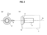
- Fig. 2 are schematic views showing the compensating part 2 of the image stabilizing device of Fig. 1 .
- Fig. 2(a) is a schematic front view of the part
- Fig. 2(b) is a schematic side view of the part.
- Fig. 3 are structural views of the compensating part of Fig. 2 .
- Fig. 3(a) is a front view.
- Fig. 3(b) is a sectional view viewed in a direction B of Fig. 2(a)
- Fig. 3(c) is a sectional view viewed in a direction A of Fig. 2(a) .
- Fig. 4 is a perspective view of the fixed prism arranged in the compensating part of Fig. 3 .
- the compensating part 2 includes the fixed prism 9 immovable in position and the movable prisms 10A, 10B rotatable about an optical axis as the rotating center.
- the fixed prism 9 includes a first face 9a perpendicular to the optical axis 1a and a second face 9b being a flat surface opposed to the first face 9a at a minute angle slant.
- the fixed prism 9 is made of acryl etc.
- the movable prisms 10A, 10B are also similar to the prism 9 in terms of shape and material.
- Fig. 5 are arrangement views of actuators and sensors that the compensating part of Fig. 2 does have.
- Fig. 5(a) is a schematic side view
- Fig. 5(b) an arrangement view of an actuator and a sensor of the movable prism 10A
- Fig. 5(c) is an arrangement view of an actuator and a sensor of the movable prism 10B.
- the actuators and the sensors are attached to the compensating part 2.
- the actuator 4A and the sensor 8A are provided for the movable prism 10A
- the actuator 4B and the sensor 8B are provided for the movable prism 10B.
- the actuators 4A, 4B rotate the movable prisms 10A, 10B in response to the control signals from the controller 6.
- the actuators 4A, 4B comprise e.g. compact pulse motors, compact linear motors, compact ultrasonic motors or the like and have small driving torques respectively.
- the sensors 8A, 8B which are formed by e.g. compact photo interrupters, MR elements, hall elements or the like, detect the rotating conditions of the movable prisms 10A, 10B and output the information about the rotating conditions to the controller 6.
- pulse motors are employed as the actuators 4A, 4B.
- the movable prisms 10A, 10B are covered, on their circumferences, with masking materials on which holes 10a, 10b are formed respectively.
- the holes 10a, 10b are positioned so as to accord with the sensors 8A, 8B when the movable prisms 10A, 10B are brought into their initial positions, respectively.
- the photo interrupter includes an infrared-emitting diode and a photo transistor.
- the photo interrupter is arranged so as to interpose the movable prism 10A or 10B between the infrared-emitting diode and the photo transistor.
- the compact photo interrupters detect their original positions since the photo transistors receive lights of the infrared-emitting diodes passing through the holes 10a, 10b. Assuming that the number of pulse is set to 0 at the original position of the prism, the information about the rotating conditions of the movable prisms 10A, 10B is obtained by counting the number of pulses at rotating,
- magnetic bodies are attached to the movable prisms 10A, 10B respectively, in lieu of the holes 10a, 10b.
- the MR elements or the hall elements detect field variances caused by the magnetic bodies rotating together with the movable prisms 10A, 10B to thereby detect the information about the rotating conditions.
- Fig. 6 are views explaining the movement of a subject image by a prism.
- Fig. 6(a) is a view explaining refraction of light by the prism
- Fig. 6(b) is a view of the prism of Fig. 6(a) viewed in its front direction (arrow a).
- the prism 11 of Fig. 6(a) is rotated by an angle " ⁇ ".
- an image of a subject "A" is shifted (of parallel translation) to a subject "A"'.
- Fig. 7 is a view showing the image shift vectors in case that the movable prisms 10A, 10B do not rotate.
- vector " ⁇ 1 ", vector “ ⁇ 2 " and vector “ ⁇ 3 " are image shift vectors by the fixed prism 9, the movable vectors 10A and 10B, respectively.
- the positions of the fixed prism 9 and the movable prisms 10A, 10B are established so that vector " ⁇ 1 " cancels a synthetic vector of vector " ⁇ 2 " and vector “ ⁇ 3 ".
- the compensating part 2 has an incident angle equal to an emitting angle, so that a subject image does not move.
- Fig. 8 are views explaining the movements of the subject image in case that the movable prisms 10A, 10B rotate.
- Fig. 8(a) is a view showing the image shift vectors when the movable prisms rotate
- Fig. 8(b) is a view where displacements of the image shift vectors of Fig. 8(a) are picked up.
- vector " ⁇ ' 2 " and vector " ⁇ ' 3 " represent image shift vectors when the movable prisms 10A, 10B rotate by angles " ⁇ 1 " and “ ⁇ 2 ", respectively.
- rotating directions shown in Fig. 8(a) are positive directions of angles " ⁇ 1 " and " ⁇ 2 ", respectively.
- vector ⁇ a vector ⁇ 2 - vector ⁇ 2
- vector ⁇ b vector ⁇ 3 - vector ⁇ 3 .
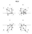
- Fig. 9 are views showing parallel translating forms of a subject image (subject).
- Fig. 9(a) is a view of the subject image moved to a second quadrant
- Fig. 9(b) a view of the subject image moved to a first quadrant
- Fig. 9(c) a view of the subject image moved to a third quadrant
- Fig. 9(d) is a view of the subject image moved to a fourth quadrant.
- the inequalities ⁇ 1 > 0 and ⁇ 2 > 0 are established because ⁇ X > 0 and ⁇ Y > 0.
- the inequalities ⁇ 1 ⁇ 0 and ⁇ 2 > 0 are established because ⁇ x ⁇ 0 and ⁇ Y > 0.
- the inequalities ⁇ 1 ⁇ 0 and ⁇ 2 ⁇ 0 are established because ⁇ x ⁇ 0 and ⁇ Y ⁇ 0.
- the inequalities ⁇ 1 > 0 and ⁇ 2 ⁇ 0 are established because ⁇ x ⁇ 0 and ⁇ Y ⁇ 0.
- the inequalities ⁇ 1 > 0 and ⁇ 2 ⁇ 0 are established because ⁇ x > 0 and ⁇ Y ⁇ 0.
- Fig. 10 are views explaining a equivalent focal distance and a shift distance.
- Fig. 10(a) is a view explaining the equivalent focal distance
- Fig. 10(b) is a view explaining the shift distance.
- Fig. 11 are views explaining the compensation of hand tremor.
- Fig. 11 (a) is a view explaining the movement of a subject image due to hand tremor
- Fig. 11 (b) is a view explaining the compensation of the movement of the subject image due to hand tremor.
- the operation of the image stabilizing device in the embodiment of the present invention will be described.
- the sensors 8A, 8B detect the rotation of the movable prisms 10A, 10B and output the information about rotation to the controller 6.
- ⁇ * ⁇ X * ⁇ ⁇ Y * .
- the controller 6 calculates a vector ⁇ based on the equations (15) to (21) and outputs control signals to the motor drive electronic circuit 7 so that the rotating angles of the movable prisms 10A, 10B become “ ⁇ 1 ", “ ⁇ 2 ", respectively.
- the motor drive electronic circuit 7 drives the actuators 4A, 4B in response to the control signals from the controller 6, while the actuators 4A, 4B rotate the movable prisms 10A, 10B so that their rotating angles become “ ⁇ 1 ", “ ⁇ 2 ", respectively.
- the image stabilizing device in the embodiment of the present invention as an unsteady image motion due to hand tremor is compensated by rotating the movable prisms 10A, 10B, it is possible to provide an image stabilizing device with its simple structure and easy fabrication.
- Fig. 12 is a view showing the lens system of Fig. 1 .
- Fig. 13(a) is a view showing the structure where the compensating part is arranged in the lens system.
- Fig. 13(b) is a view showing the structure where the compensating part is arranged behind the lens system.
- the lens system 3 comprises first to fourth lens groups 3a to 3d. Although eliminated in the Behind the lens system 3, there are an optical low-pass filter 16 for suppressing noise (false signal) and the CCD 13 for imaging a subject image although they are not shown in Fig. 1 .
- the compensating part 2 is arranged in front of the lens system 3 as shown in Fig. 12 , although the compensating part 2 may be arranged inside the lens system 3, as shown in Fig. 13(a) . Alternatively, as shown in Fig. 13(b) , the compensating part 2 may be arranged behind the lens system 3. Consequently, as it becomes possible to arrange the compensating part 2 in a narrow part of light flux passing through the lens system 3, the compensating part 2 can be small-sized.
- the compensating part 2 includes the fixed prism 9 and the movable prisms 10A, 10B, although the fixed prism 9 may be deleted from the device. Alternatively, an additional fixed prism may be subjoined to the device.
- Fig. 14 illustrates a compensating part with no fixed prism.
- Fig. 14(a) is a front view of the part
- Fig. 14(b) a plan view
- Fig. 14(c) is a side view.
- Fig. 15 illustrates a compensating part with two sheets of fixed prisms.
- Fig. 15(a) is a front view of the part
- Fig. 15(b) a plan view
- Fig. 15(c) is a side view.
- a prism angle of the fixed prism 9 so that the chromatic aberration is level with at an intermediate position between the chromatic aberration in cases of Figs. 3 and 15 and that in case of Fig. 14 .
- each prism may be in the form of a simplex prism or a compound prism.
- the prism may be formed by a parallel plate having prism effect.
- Fig. 16 illustrates the other constitution of the prism of the present invention.
- Fig. 16(a) is a view showing a simplex prism
- Fig. 16(b) a view of a compound prism
- Fig. 16(c) is a view showing a parallel plate having prism effect.
- the movable prism 10A may be in the form of a compound prism produced by bonding two sheets of prisms 10Aa, 10Ab with minute angles.
- a compound prism it is possible to greaten an angle of each prism unit, allowing a minute-angle prism, that would be made from a simplex prism with difficulty, to be manufactured with easiness.
- the prism requires a control of its inclination angle in production, while the parallel plate 17 is easy to be machined.
- the image stabilizing device of the present invention includes a pair of movable refractive elements changing a refracting direction of light incident on the optical lens to thereby detect shake produced in the imaging equipment, and further rotates the movable refractive elements perpendicularly to the optical axis and independently of each other to thereby compensate an unsteady image motion. Therefore, according to the present invention, it is possible to provide an image stabilizing device with both simple constitution and easy fabrication.
Landscapes
- Physics & Mathematics (AREA)
- Engineering & Computer Science (AREA)
- Multimedia (AREA)
- Signal Processing (AREA)
- General Physics & Mathematics (AREA)
- Optics & Photonics (AREA)
- Adjustment Of Camera Lenses (AREA)
- Studio Devices (AREA)
Abstract
An image stabilizing device is provided, in a video camera, with a compensating part 2 having movable prisms 10A, 10B rotatable independently of each other. The movable prisms 10A, 10B are rotated in response to shakes of the video camera due to hand tremor.
Description
- The present invention relates to an image stabilizing device applicable to an equipment having optical lenses, such as video camera, electronic still camera and still camera, for compensating unstable image motion due to shake of the equipment.
- There has been conventionally known a video camera equipment having a camera body equipped with an image stabilizing device for compensating hand tremor at picking up images in order to make the images easily viewable at playback. Patent Document No. 1 (Japanese Patent Publication Laid-open No.
9-51469 - An active prism used in Patent Document No. 1 has a structure in which between two sheets of glass plates connected to each other through an expandable bellows of special film, there is charged liquid having the substantially same refraction index as that of the glasses.
- This active prism is arranged between a CCD image sensor and an objective lens of a lens unit for leading a subject image to the CCD image sensor to compensate hand tremor by changing respective tilting angles of respective glass plates (referred to as "apex angles") to a video camera body in a vertical or horizontal direction.
- Therefore, the image stabilizing device adopting the active prism technique has advantages of small power consumption, easiness for miniaturization, less deterioration in resolution and relatively wide compensation area.
- With the prevention of "shake" in a playback image by compensating hand tremor in this active prism method, it becomes possible to realize a compact and lightweight "handy-type" video camera unit with high image quality.
- Further, if arranging an active prism in front of the lens unit, then the compensation is completed on the side of a subject irrespective of the lens unit. In other words, this active prism would become effective to all lens system in theory, exhibiting its expanded versatility. Further, the active prism may be attached to an exterior of the video camera unit.
- However, the active prism has the above-mentioned structure in which between two glass plates connected to each other through the expandable bellows of special film, there is charged liquid having the substantially same refraction index as that of the glasses. Thus, there is required a technique of completely enclosing the liquid in the bellows without producing air bubbles. This leads to complication in structure and difficulty in fabrication.
- Under the situation, there has been long-awaited advent of an image stabilizing device which has image stabilizing effect similar to that of the active prism, with simpler constitution and easy fabrication.
- In consideration of the above-mentioned issue, an object of the present invention is to provide an image stabilizing device with simpler constitution and easy fabrication.
- In order to attain the above object, according to a main aspect of the present invention, there is provided an image stabilizing device that optically compensates shake of images picked up by an imaging equipment having an optical lens, the device comprising: a shake detector that detects shake of the imaging equipment; a pair of movable refractive elements arranged on an incident side of the optical lens to change a refracting direction of light incident on the optical lens; two rotators that rotate the movable refractive elements perpendicularly to an optical axis, respectively and independently of each other; and a controller that rotation-controls the two rotators to cancel the shake detected by the shake detector.
-
-
Fig. 1 is a block diagram showing the constitution of an image stabilizing device in accordance with an embodiment of the present invention. -
Fig. 2 are schematic views showing a compensating part of the image stabilizing device shown inFig. 1 , in whichFig. 2(a) is a schematic front view andFig. 2(b) is a schematic side view. -
Fig. 3 are structural views of the compensating part shown inFig. 2 , in whichFig. 3(a) is a front view,Fig. 3(b) a sectional view viewed in a direction B ofFig. 2(a) , andFig. 3(c) is a sectional view viewed in a direction A ofFig. 2(a) . -
Fig. 4 is a perspective view of a fixed prism that the compensating part ofFig. 3 includes. -
Fig. 5 are arrangement views of actuators and sensors that the compensating part ofFig. 3 includes, in whichFig. 5(a) is a schematic side view,Fig. 5(b) an arrangement view of an actuator and a sensor of amovable prism 10A, andFig. 5(c) is an arrangement view of an actuator and a sensor of amovable prism 10B. -
Fig. 6 are views explaining the movement of a subject image by a prism, in whichFig. 6(a) is a view explaining refraction of light by the prism andFig. 6(b) is a view of the prism ofFig. 6(a) viewed in its front direction. -
Fig. 7 is a view showing image shift vectors when movable prisms do not rotate. -
Fig. 8 are views explaining the movement of a subject image when the movable prisms rotate, in whichFig. 8(a) is a view showing the image shift vectors when the movable prisms rotate andFig. 8(b) is a view where displacements of the image shift vectors ofFig. 8(a) are picked up. -
Fig. 9 are views showing parallel translating forms of a subject image (subject), in whichFig. 9(a) is a view of the subject image moved to a second quadrant,Fig. 9(b) a view of the subject image moved to a first quadrant,Fig. 9(c) a view of the subject image moved to a third quadrant, andFig. 9(d) is a view of the subject image moved to a fourth quadrant. -
Fig. 10 are views explaining a equivalent focal distance and a shift angle, in whichFig. 10(a) is a view explaining the equivalent focal distance andFig. 10(b) is a view explaining a shift distance. -
Fig. 11 are views explaining the compensation of hand tremor, in whichFig. 11 (a) is a view explaining the movement of a subject image due to hand tremor andFig. 11 (b) is a view explaining the compensation of the movement of the subject image due to hand tremor. -
Fig. 12 is a view showing the lens system ofFig. 1 . -
Fig. 13 are views showing the arrangement of the compensating part, the lens system and others ofFig. 1 , in whichFig. 13(a) is a view showing the compensating part arranged in the lens system andFig. 13(b) is a view showing the compensating part arranged behind the lens system. -
Fig. 14 are views showing the compensating part without a fixed prism as another constitution of the compensating part of the present invention, in whichFig. 14(a) is a front view of the compensating part,Fig. 14(b) a plan view of the part, andFig. 14(c) is a side view of the part. -
Fig. 15 are views showing the compensating part with two sheets of fixed prisms as the other constitution of the compensating part of the present invention, in whichFig. 15(a) is a front view of the compensating part,Fig. 15(b) a plan view of the part, andFig. 15(c) is a side view of the part. -
Fig. 16 are views showing the other constitution of the prism of the present invention, in whichFig. 16(a) is a view showing a simplex prism,Fig. 16(b) a view of a compound prism, andFig. 16(c) is a view showing a parallel plate having prism effect. - There will be described a preferred embodiment for embodying an image stabilizing device of the present invention with reference to drawings.
-
Fig. 1 is a block diagram showing the constitution of an image stabilizing device in accordance with an embodiment of the present invention. The image stabilizing device of the present invention is provided in, for example, a well-knownvideo camera 1. - The image stabilizing device in the embodiment of the present invention includes a compensating
part 2 having a pair ofmovable prisms Fig. 3(b) ) independently rotatable about anoptical axis 1a as a rotating center and a fixed prism 9 (Fig. 3(b) ), alens system 3 for taking pictures of a subject,actuators movable prisms shake detecting part 5 for detecting shake of thevideo camera 1 due to hand tremor etc. and generating hand-tremor signals, acontroller 6 that transmits control signals to theactuators shake detecting part 5, a motor drive electronic circuit (MDE) 7 for driving theactuators controller 6 andsensors Figs.5(b) and 5(c) ) for detecting rotations of the movable prisms in the compensatingpart 2. - The
shake detecting part 5 comprises first and second angular speed sensors having respective detecting faces opposed in vertical and horizontal directions of thevideo camera 1. The first and the second angular speed sensors are provided to respectively detect angular speeds derived from a horizontal shake direction and a vertical shake direction and also formed by well-known angular speed sensors, such as gyro sensors. -
Figs. 2 to 5 are views explaining the operation of detecting rotations or rotating conditions of the prisms, although details of a rotator and a detector are eliminated since they are well known. -
Fig. 2 are schematic views showing thecompensating part 2 of the image stabilizing device ofFig. 1 .Fig. 2(a) is a schematic front view of the part, whileFig. 2(b) is a schematic side view of the part.Fig. 3 are structural views of the compensating part ofFig. 2 .Fig. 3(a) is a front view.Fig. 3(b) is a sectional view viewed in a direction B ofFig. 2(a) , whileFig. 3(c) is a sectional view viewed in a direction A ofFig. 2(a) .Fig. 4 is a perspective view of the fixed prism arranged in the compensating part ofFig. 3 . - As shown in
Figs. 3(a) to 3(c) , the compensatingpart 2 includes thefixed prism 9 immovable in position and themovable prisms - As shown in
Fig. 4 , thefixed prism 9 includes afirst face 9a perpendicular to theoptical axis 1a and asecond face 9b being a flat surface opposed to thefirst face 9a at a minute angle slant. Thefixed prism 9 is made of acryl etc. Themovable prisms prism 9 in terms of shape and material. -
Fig. 5 are arrangement views of actuators and sensors that the compensating part ofFig. 2 does have.Fig. 5(a) is a schematic side view,Fig. 5(b) an arrangement view of an actuator and a sensor of themovable prism 10A, andFig. 5(c) is an arrangement view of an actuator and a sensor of themovable prism 10B. The actuators and the sensors are attached to thecompensating part 2. As shown inFigs. 5(b) and 5(c) , theactuator 4A and thesensor 8A are provided for themovable prism 10A, while theactuator 4B and thesensor 8B are provided for themovable prism 10B. - The
actuators movable prisms controller 6. Theactuators - The
sensors movable prisms controller 6. - If adopting the compact photo interrupters for the
sensors actuators movable prisms holes holes sensors movable prisms - The photo interrupter includes an infrared-emitting diode and a photo transistor. The photo interrupter is arranged so as to interpose the
movable prism - When the device is powered on to rotate the
movable prisms holes movable prisms - If adopting MR elements or hall elements for the
sensors movable prisms holes - The MR elements or the hall elements detect field variances caused by the magnetic bodies rotating together with the
movable prisms -
Fig. 6 are views explaining the movement of a subject image by a prism.Fig. 6(a) is a view explaining refraction of light by the prism, whileFig. 6(b) is a view of the prism ofFig. 6(a) viewed in its front direction (arrow a). InFig. 6(b) , theprism 11 ofFig. 6(a) is rotated by an angle "α". As shown inFigs. 6(a) and 6(b) , an image of a subject "A" is shifted (of parallel translation) to a subject "A"'. - In
Figs. 6(a) and 6(b) , "i" denotes a prism angle (incident angle of light) of theprism 11, "L" a prism length, "δ" a prism height, "δ1" a prism height at the thinnest part, "N" a refraction index, "i'" a refraction angle of light, "θ" an image shift angle (deflection angle), "α" a rotation angle of the prism, "Lα" a rotation length of the prism, "vector e" a unit vector in the direction of image shifting direction "θ", and "vector θ" an image shift vector. Assume here that the suffix "vector" represents a vector quantity. InFigs. 6 to 11 , these vector quantities are represented by bold faces in place of suffix "vector". Here, the following relationship is established:
-
Fig. 6(a) shows that, among the prism angle (incident angle) "i", the refraction angle "i'" and the image shift angle (deflection angle) "θ", there is established:
- In addition, Snell's law leads to

- Assuming now that the prism angle "i" is small, the equation (3) can be approximated as

- Therefore, substituting the equation (4) into the equation (2) gives

- Further,
Fig. 6(b) shows that, between the prism rotation length "Lα" and the prism rotation angle "α", there is established:
that is,
- Furthermore, the following relationship is established as well:

that is,
-
Fig. 7 is a view showing the image shift vectors in case that themovable prisms Fig. 7 , vector "θ1", vector "θ2" and vector "θ3" are image shift vectors by the fixedprism 9, themovable vectors Fig. 7 , the positions of the fixedprism 9 and themovable prisms prism 9 and themovable prisms part 2 has an incident angle equal to an emitting angle, so that a subject image does not move. -
Fig. 8 are views explaining the movements of the subject image in case that themovable prisms Fig. 8(a) is a view showing the image shift vectors when the movable prisms rotate, whileFig. 8(b) is a view where displacements of the image shift vectors ofFig. 8(a) are picked up. - Assume in
Fig. 8(a) , vector "θ'2" and vector "θ'3" represent image shift vectors when themovable prisms Fig. 8(a) are positive directions of angles "α1" and "α2", respectively. Suppose that the following relationships are established:

- Then, as shown in
Fig. 8(b) , the image of the subject "A" move to "A"' in translation. Then, as a synthetic vector of vector "θa" and vector "θb", the image shift vector is described as
Then,Figs. 8(a) and 8(b) show that the following relationships are established:

- Here, consider a vector having components "α1" and "α2", that is, vector α = (α1, α2). Resolving the equations (13) and (14) with respect to "α1", "α2" gives


where


-
Fig. 9 are views showing parallel translating forms of a subject image (subject).Fig. 9(a) is a view of the subject image moved to a second quadrant,Fig. 9(b) a view of the subject image moved to a first quadrant,Fig. 9(c) a view of the subject image moved to a third quadrant, andFig. 9(d) is a view of the subject image moved to a fourth quadrant. - When the subject image moves into the first quadrant, as shown in
Fig. 9(b) , the inequalities α1 > 0 and α2 > 0 are established because θX > 0 and θY> 0. Further, when the subject image moves into the second quadrant, as shown inFig. 9(a) , the inequalities α1 < 0 and α2 > 0 are established because θx < 0 and θY > 0. Still further, when the subject image moves into the third quadrant, as shown inFig. 9(c) , the inequalities α1 < 0 and α2 < 0 are established because θx < 0 and θY < 0. Again, when the subject image moves into the fourth quadrant, as shown inFig. 9(d) , the inequalities α1 > 0 and α2 < 0 are established because θx > 0 and θY < 0. -
Fig. 10 are views explaining a equivalent focal distance and a shift distance.Fig. 10(a) is a view explaining the equivalent focal distance, whileFig. 10(b) is a view explaining the shift distance. - In
Fig. 10(a) , "SF" denotes a distance between a subject "A" and a first principal point of thelens system 3, and "f" denotes a focal length of thelens system 3. Then, the equivalent focal distance "fm" is identical to a distance between a second principal point of thelens system 3 and aCCD 13 for imaging asubject image 14A, and is represented by
where
- Suppose that the compensating
part 2 is inserted so that thesubject image 14A is displaced to asubject image 14A' with an image shift angle "θ", as shown inFig. 10(b) . Then, a shift distance "S" is expressed by
-
Fig. 11 are views explaining the compensation of hand tremor.Fig. 11 (a) is a view explaining the movement of a subject image due to hand tremor, whileFig. 11 (b) is a view explaining the compensation of the movement of the subject image due to hand tremor. - As shown in
Fig. 11 (a) , an upward rotating of a main body such as video camera would cause the subject A to be rotated relatively downward. As a result, thesubject image 14A is shifted to thesubject image 14A' running off theCCD 13. Here, supposing a shake angle as "0*" and a unit vector in the direction of shake as "vector e*" (= - vector e), a shake-angle vector "vector θ*" is represented by
-
Fig. 11 (b) shows that a situation in which the compensatingpart 2 is inserted in front of thelens system 3. Then, if the image shift vector "θ" and the shake-angle vector "θ*" satisfy with the shake compensating condition:
thesubject image 14A' is moved to the position of thesubject image 14A, so that the shake is compensated.
Next, the operation of the image stabilizing device in the embodiment of the present invention will be described. - The
sensors movable prisms controller 6. - The
shake detecting part 5 detects shake of thevideo camera 1 due to hand tremor and outputs the shake in the form of a shake signal to thecontroller 6. Based on the shake signal, thecontroller 6 calculates a shake angle vector "θ*", representing the magnitude of the shake and its direction, by
Here, using the equation (26) gives
- The
controller 6 calculates a vector α based on the equations (15) to (21) and outputs control signals to the motor drive electronic circuit 7 so that the rotating angles of themovable prisms - Then, the motor drive electronic circuit 7 drives the
actuators controller 6, while theactuators movable prisms - According to the image stabilizing device in the embodiment of the present invention, as an unsteady image motion due to hand tremor is compensated by rotating the
movable prisms - Note, although the
lens system 3 is illustrated in the form of one block inFig. 1 , thelens system 3 is actually formed by a plurality of lenses in group.Fig. 12 is a view showing the lens system ofFig. 1 .Fig. 13(a) is a view showing the structure where the compensating part is arranged in the lens system.Fig. 13(b) is a view showing the structure where the compensating part is arranged behind the lens system. - The
lens system 3 comprises first tofourth lens groups 3a to 3d. Although eliminated in the Behind thelens system 3, there are an optical low-pass filter 16 for suppressing noise (false signal) and theCCD 13 for imaging a subject image although they are not shown inFig. 1 . - In
Fig. 1 , the compensatingpart 2 is arranged in front of thelens system 3 as shown inFig. 12 , although the compensatingpart 2 may be arranged inside thelens system 3, as shown inFig. 13(a) . Alternatively, as shown inFig. 13(b) , the compensatingpart 2 may be arranged behind thelens system 3. Consequently, as it becomes possible to arrange the compensatingpart 2 in a narrow part of light flux passing through thelens system 3, the compensatingpart 2 can be small-sized. - In the above-mentioned embodiment, the compensating
part 2 includes the fixedprism 9 and themovable prisms prism 9 may be deleted from the device. Alternatively, an additional fixed prism may be subjoined to the device. - As another constitution of the compensating part of the present invention,
Fig. 14 illustrates a compensating part with no fixed prism.Fig. 14(a) is a front view of the part,Fig. 14(b) a plan view, andFig. 14(c) is a side view. As the other constitution of the compensating part of the present invention,Fig. 15 illustrates a compensating part with two sheets of fixed prisms.Fig. 15(a) is a front view of the part,Fig. 15(b) a plan view, andFig. 15(c) is a side view. - In case of
Fig. 15 , the positions of respective prisms are adjusted so that the compensatingpart 2 in its initial state has an incident angle equal to an emitting angle. In common withFig. 14 andFig. 15 , the other operation is similar to that in the above-mentioned embodiment, accomplishing the similar effect. - As it will be understood from the equations (10) and (11), although the image is misaligned in the initial state in case of
Fig. 14 , the misalignment is not concerned with the compensation of unsteady image motion directly. Although the device is constructed that the incident angle on the compensatingpart 2 in the initial state becomes equal to the emitting angle in cases ofFigs. 3 and15 , such a formation comes from the purpose of minimizing the influence of prism effect at image stabilizing on chromatic aberration. In case ofFig. 14 , the chromatic aberration gets large in comparison with the cases ofFigs. 3 and15 . However, according to the constitution with no prism ofFig. 14 , it is possible to minimize the device by shortening a length of the compensatingpart 2 in the direction of the optical axis. - Further, in order to balance suppression of the influence on chromatic aberration and miniaturization of the compensating
part 2, it is also possible to adjust a prism angle of the fixedprism 9 so that the chromatic aberration is level with at an intermediate position between the chromatic aberration in cases ofFigs. 3 and15 and that in case ofFig. 14 . - In the above-mentioned embodiment, additionally, each prism may be in the form of a simplex prism or a compound prism. Alternatively, the prism may be formed by a parallel plate having prism effect.
Fig. 16 illustrates the other constitution of the prism of the present invention.Fig. 16(a) is a view showing a simplex prism,Fig. 16(b) a view of a compound prism, andFig. 16(c) is a view showing a parallel plate having prism effect. - For instance, as shown in
Fig. 16(b) , themovable prism 10A may be in the form of a compound prism produced by bonding two sheets of prisms 10Aa, 10Ab with minute angles. In case of a compound prism, it is possible to greaten an angle of each prism unit, allowing a minute-angle prism, that would be made from a simplex prism with difficulty, to be manufactured with easiness. - Further, as shown in
Fig. 16(c) , each prism may be replaced by aparallel plate 17 having prism effect with a refraction index N changed from N = 1.5 to N= 1.4. The prism requires a control of its inclination angle in production, while theparallel plate 17 is easy to be machined. - The image stabilizing device of the present invention includes a pair of movable refractive elements changing a refracting direction of light incident on the optical lens to thereby detect shake produced in the imaging equipment, and further rotates the movable refractive elements perpendicularly to the optical axis and independently of each other to thereby compensate an unsteady image motion. Therefore, according to the present invention, it is possible to provide an image stabilizing device with both simple constitution and easy fabrication.
Claims (4)
- An image stabilizing device that optically compensates shake of images picked up by an imaging equipment having an optical lens, the device comprising:a shake detector that detects shake of the imaging equipment;a pair of movable refractive elements arranged on an incident side of the optical lens to change a refracting direction of light incident on the optical lens;two rotators that rotate the movable refractive elements perpendicularly to an optical axis, respectively and independently of each other; anda controller that rotation-controls the two rotators to cancel the shake detected by the shake detector.
- The image stabilizing device of claim 1, wherein at least one of the pair of movable refractive elements is a compound prism formed by two or more prisms laid on each other in the direction of the optical axis.
- The image stabilizing device of claim 1 or 2, further comprising a fixed refractive element fixed in proximity to the pair of movable refractive elements, wherein
when rotating angles of the pair of movable refractive elements are constant angles, a difference between an incident angle on a refractive-element group of the pair of movable refractive elements and the fixed refractive element and an emitting angle of the refractive-element group is less than a difference between an incident angle on the pair of movable refractive elements and an emitting angle thereof. - The image stabilizing device of claim 3, wherein the fixed refractive element is a compound prism formed by two or more prisms laid on each other in the direction of the optical axis.
Applications Claiming Priority (2)
| Application Number | Priority Date | Filing Date | Title |
|---|---|---|---|
| JP2005246407 | 2005-08-26 | ||
| PCT/JP2006/316090 WO2007023718A1 (en) | 2005-08-26 | 2006-08-16 | Image shake correcting device |
Publications (1)
| Publication Number | Publication Date |
|---|---|
| EP1947507A1 true EP1947507A1 (en) | 2008-07-23 |
Family
ID=37771467
Family Applications (1)
| Application Number | Title | Priority Date | Filing Date |
|---|---|---|---|
| EP06796450A Withdrawn EP1947507A1 (en) | 2005-08-26 | 2006-08-16 | Image shake correcting device |
Country Status (5)
| Country | Link |
|---|---|
| US (1) | US20090059374A1 (en) |
| EP (1) | EP1947507A1 (en) |
| JP (1) | JPWO2007023718A1 (en) |
| CN (1) | CN101253448A (en) |
| WO (1) | WO2007023718A1 (en) |
Families Citing this family (4)
| Publication number | Priority date | Publication date | Assignee | Title |
|---|---|---|---|---|
| JP5332176B2 (en) * | 2007-09-19 | 2013-11-06 | 株式会社Jvcケンウッド | Image blur correction device |
| JP5446669B2 (en) * | 2009-09-28 | 2014-03-19 | ソニー株式会社 | Optical apparatus and imaging apparatus |
| CN112567729A (en) * | 2019-11-25 | 2021-03-26 | 深圳市大疆创新科技有限公司 | Control device, imaging system, mobile body, control method, and program |
| TWI721735B (en) * | 2019-12-25 | 2021-03-11 | 吉佳科技股份有限公司 | Optical focusing device with shake compensation |
Family Cites Families (13)
| Publication number | Priority date | Publication date | Assignee | Title |
|---|---|---|---|---|
| BE792931A (en) * | 1972-10-16 | 1973-06-18 | Optigon Res & Dev Corp | DEVICE FOR STABILIZING THE IMAGE OF AN OPTICAL INSTRUMENT SUBJECT TO ANGULAR VIBRATIONS |
| DE2353101C3 (en) * | 1972-10-25 | 1979-01-18 | Fraser-Volpe Corp., Warrington, Pa. (V.St.A.) | Telescope with image stabilization |
| US4676593A (en) * | 1983-04-18 | 1987-06-30 | Asahi Kogaku Kogyo Kabushiki Kaisha | Eyepiece and photographing device for fiberscope |
| JPS6027278A (en) * | 1983-07-25 | 1985-02-12 | Fuji Photo Optical Co Ltd | Solid-state image pickup camera |
| JPS63169614A (en) * | 1987-01-07 | 1988-07-13 | Oputo:Kk | Image stabilizing device |
| US5333076A (en) * | 1988-01-21 | 1994-07-26 | Fairchild Weston Systems, Inc. | Stabilized imaging system |
| JPH0394214A (en) * | 1989-09-06 | 1991-04-19 | Asahi Optical Co Ltd | Image stabilizing device |
| DE4028359C2 (en) * | 1989-09-06 | 1994-05-19 | Asahi Optical Co Ltd | Image stabilization device |
| JPH04352124A (en) * | 1991-05-30 | 1992-12-07 | Toshihiro Tsumura | Optical axis deflection device for optical equipment |
| JPH10254008A (en) * | 1997-03-12 | 1998-09-25 | Sony Corp | Actuator and lens driving device in optical axis angle variable device |
| JPH11146260A (en) * | 1997-11-13 | 1999-05-28 | Canon Inc | Shake correction device, shake correction method, and computer-readable storage medium |
| JP3929778B2 (en) * | 2002-01-16 | 2007-06-13 | 株式会社リコー | Imaging device |
| JP2004301939A (en) * | 2003-03-28 | 2004-10-28 | Sony Corp | Camera system, camera, and interchangeable lens |
-
2006
- 2006-08-16 US US11/990,932 patent/US20090059374A1/en not_active Abandoned
- 2006-08-16 WO PCT/JP2006/316090 patent/WO2007023718A1/en not_active Ceased
- 2006-08-16 JP JP2007532073A patent/JPWO2007023718A1/en not_active Withdrawn
- 2006-08-16 EP EP06796450A patent/EP1947507A1/en not_active Withdrawn
- 2006-08-16 CN CNA2006800312914A patent/CN101253448A/en active Pending
Non-Patent Citations (1)
| Title |
|---|
| See references of WO2007023718A1 * |
Also Published As
| Publication number | Publication date |
|---|---|
| US20090059374A1 (en) | 2009-03-05 |
| CN101253448A (en) | 2008-08-27 |
| JPWO2007023718A1 (en) | 2009-02-26 |
| WO2007023718A1 (en) | 2007-03-01 |
Similar Documents
| Publication | Publication Date | Title |
|---|---|---|
| US12153330B2 (en) | Anti-shake compensation structure for auto-focus | |
| CN111355872B (en) | Camera module, anti-shake subassembly and terminal | |
| US4780739A (en) | Anti-vibration imaging device | |
| US4788596A (en) | Image stabilizing device | |
| EP0669757B1 (en) | Image sensing apparatus | |
| US8446672B2 (en) | Vibration reduction apparatus with a center of gravity adjusting member to reduce detection errors and optical apparatus | |
| CN100523986C (en) | Anti-shake apparatus | |
| US9417458B2 (en) | Image stabilizing device and system for telescopic optical instruments | |
| US5657080A (en) | Photographing system for detecting and correcting camera shake | |
| JPH0421815A (en) | Image stabilization lens system | |
| US6243132B1 (en) | Jitter control apparatus for video camera | |
| EP2034355B1 (en) | Image blurring correction device | |
| JP4973219B2 (en) | Optical equipment | |
| US20090059374A1 (en) | Image stabilizing device | |
| JPH07104337A (en) | Anti-shake device | |
| JPS6266774A (en) | Image deflection device of imaging device | |
| JPS63169614A (en) | Image stabilizing device | |
| JP4042170B2 (en) | Anti-vibration telescope | |
| JP2009031353A (en) | Imaging apparatus | |
| EP2028540A1 (en) | Image blur correcting device | |
| JP3206075B2 (en) | Anti-sway device | |
| RU2315255C1 (en) | Object signing system | |
| JPH0777659A (en) | Multi-eye optical device | |
| JP4618004B2 (en) | Imaging device | |
| JP2007316428A (en) | Image-shake correcting attachment |
Legal Events
| Date | Code | Title | Description |
|---|---|---|---|
| PUAI | Public reference made under article 153(3) epc to a published international application that has entered the european phase |
Free format text: ORIGINAL CODE: 0009012 |
|
| 17P | Request for examination filed |
Effective date: 20080303 |
|
| AK | Designated contracting states |
Kind code of ref document: A1 Designated state(s): DE FR GB |
|
| DAX | Request for extension of the european patent (deleted) | ||
| RBV | Designated contracting states (corrected) |
Designated state(s): DE FR GB |
|
| STAA | Information on the status of an ep patent application or granted ep patent |
Free format text: STATUS: THE APPLICATION HAS BEEN WITHDRAWN |
|
| 18W | Application withdrawn |
Effective date: 20090817 |