EP1947385A1 - Vorrichtung zur Kraftstoffeinspritzung in eine Strömungsmaschine - Google Patents
Vorrichtung zur Kraftstoffeinspritzung in eine Strömungsmaschine Download PDFInfo
- Publication number
- EP1947385A1 EP1947385A1 EP20080290031 EP08290031A EP1947385A1 EP 1947385 A1 EP1947385 A1 EP 1947385A1 EP 20080290031 EP20080290031 EP 20080290031 EP 08290031 A EP08290031 A EP 08290031A EP 1947385 A1 EP1947385 A1 EP 1947385A1
- Authority
- EP
- European Patent Office
- Prior art keywords
- piston
- pressurization
- threshold
- orifice
- fuel
- Prior art date
- Legal status (The legal status is an assumption and is not a legal conclusion. Google has not performed a legal analysis and makes no representation as to the accuracy of the status listed.)
- Granted
Links
- 239000000446 fuel Substances 0.000 title claims abstract description 46
- 238000002347 injection Methods 0.000 title claims description 9
- 239000007924 injection Substances 0.000 title claims description 9
- 230000007704 transition Effects 0.000 claims description 6
- 238000006073 displacement reaction Methods 0.000 claims description 3
- 239000002828 fuel tank Substances 0.000 description 3
- 238000002485 combustion reaction Methods 0.000 description 2
- 238000010586 diagram Methods 0.000 description 2
- 239000007858 starting material Substances 0.000 description 2
- 230000000694 effects Effects 0.000 description 1
- 239000000463 material Substances 0.000 description 1
- 230000004048 modification Effects 0.000 description 1
- 238000012986 modification Methods 0.000 description 1
- 230000002093 peripheral effect Effects 0.000 description 1
- 239000000243 solution Substances 0.000 description 1
- 230000001131 transforming effect Effects 0.000 description 1
Images

Classifications
-
- F—MECHANICAL ENGINEERING; LIGHTING; HEATING; WEAPONS; BLASTING
- F23—COMBUSTION APPARATUS; COMBUSTION PROCESSES
- F23K—FEEDING FUEL TO COMBUSTION APPARATUS
- F23K5/00—Feeding or distributing other fuel to combustion apparatus
- F23K5/02—Liquid fuel
- F23K5/14—Details thereof
- F23K5/147—Valves
-
- F—MECHANICAL ENGINEERING; LIGHTING; HEATING; WEAPONS; BLASTING
- F02—COMBUSTION ENGINES; HOT-GAS OR COMBUSTION-PRODUCT ENGINE PLANTS
- F02C—GAS-TURBINE PLANTS; AIR INTAKES FOR JET-PROPULSION PLANTS; CONTROLLING FUEL SUPPLY IN AIR-BREATHING JET-PROPULSION PLANTS
- F02C7/00—Features, components parts, details or accessories, not provided for in, or of interest apart form groups F02C1/00 - F02C6/00; Air intakes for jet-propulsion plants
- F02C7/22—Fuel supply systems
- F02C7/232—Fuel valves; Draining valves or systems
-
- F—MECHANICAL ENGINEERING; LIGHTING; HEATING; WEAPONS; BLASTING
- F02—COMBUSTION ENGINES; HOT-GAS OR COMBUSTION-PRODUCT ENGINE PLANTS
- F02C—GAS-TURBINE PLANTS; AIR INTAKES FOR JET-PROPULSION PLANTS; CONTROLLING FUEL SUPPLY IN AIR-BREATHING JET-PROPULSION PLANTS
- F02C7/00—Features, components parts, details or accessories, not provided for in, or of interest apart form groups F02C1/00 - F02C6/00; Air intakes for jet-propulsion plants
- F02C7/22—Fuel supply systems
- F02C7/236—Fuel delivery systems comprising two or more pumps
-
- F—MECHANICAL ENGINEERING; LIGHTING; HEATING; WEAPONS; BLASTING
- F02—COMBUSTION ENGINES; HOT-GAS OR COMBUSTION-PRODUCT ENGINE PLANTS
- F02C—GAS-TURBINE PLANTS; AIR INTAKES FOR JET-PROPULSION PLANTS; CONTROLLING FUEL SUPPLY IN AIR-BREATHING JET-PROPULSION PLANTS
- F02C9/00—Controlling gas-turbine plants; Controlling fuel supply in air- breathing jet-propulsion plants
- F02C9/26—Control of fuel supply
- F02C9/263—Control of fuel supply by means of fuel metering valves
-
- Y—GENERAL TAGGING OF NEW TECHNOLOGICAL DEVELOPMENTS; GENERAL TAGGING OF CROSS-SECTIONAL TECHNOLOGIES SPANNING OVER SEVERAL SECTIONS OF THE IPC; TECHNICAL SUBJECTS COVERED BY FORMER USPC CROSS-REFERENCE ART COLLECTIONS [XRACs] AND DIGESTS
- Y10—TECHNICAL SUBJECTS COVERED BY FORMER USPC
- Y10T—TECHNICAL SUBJECTS COVERED BY FORMER US CLASSIFICATION
- Y10T137/00—Fluid handling
- Y10T137/2496—Self-proportioning or correlating systems
- Y10T137/2559—Self-controlled branched flow systems
- Y10T137/2562—Dividing and recombining
-
- Y—GENERAL TAGGING OF NEW TECHNOLOGICAL DEVELOPMENTS; GENERAL TAGGING OF CROSS-SECTIONAL TECHNOLOGIES SPANNING OVER SEVERAL SECTIONS OF THE IPC; TECHNICAL SUBJECTS COVERED BY FORMER USPC CROSS-REFERENCE ART COLLECTIONS [XRACs] AND DIGESTS
- Y10—TECHNICAL SUBJECTS COVERED BY FORMER USPC
- Y10T—TECHNICAL SUBJECTS COVERED BY FORMER US CLASSIFICATION
- Y10T137/00—Fluid handling
- Y10T137/2496—Self-proportioning or correlating systems
- Y10T137/2559—Self-controlled branched flow systems
- Y10T137/2574—Bypass or relief controlled by main line fluid condition
- Y10T137/2605—Pressure responsive
- Y10T137/2617—Bypass or relief valve biased open
- Y10T137/262—Increasing pressure progressively closes then reopens by-pass or relief valve
-
- Y—GENERAL TAGGING OF NEW TECHNOLOGICAL DEVELOPMENTS; GENERAL TAGGING OF CROSS-SECTIONAL TECHNOLOGIES SPANNING OVER SEVERAL SECTIONS OF THE IPC; TECHNICAL SUBJECTS COVERED BY FORMER USPC CROSS-REFERENCE ART COLLECTIONS [XRACs] AND DIGESTS
- Y10—TECHNICAL SUBJECTS COVERED BY FORMER USPC
- Y10T—TECHNICAL SUBJECTS COVERED BY FORMER US CLASSIFICATION
- Y10T137/00—Fluid handling
- Y10T137/7722—Line condition change responsive valves
- Y10T137/7723—Safety cut-off requiring reset
- Y10T137/7725—Responsive to both high and low pressure or velocity
Definitions
- the invention relates to a fuel injection device in a turbomachine such as an airplane turbojet or turboprop.
- This device comprises, in general, at least one high pressure pump driven by the turbomachine turbine and whose inlet is connected to a fuel tank and the outlet to controlled flow control means comprising a metering valve and which are themselves connected, by a pressurizing means and cut-off sometimes called stop-valve, to fuel injectors located in the combustion chamber of the turbomachine.
- the pressurizing and cutting means comprises a piston displaceable in a cylindrical body between opening and closing positions of a feed pipe of the fuel injectors, this piston being sensitive on the one hand to the fuel pressure in outlet of the metering valve and secondly at a control pressure so as to close the supply conduit of the injectors as the fuel pressure remains below a predetermined threshold.
- variable pitch vanes (these equipment being called variable geometry equipment) in the following).
- the speed of restart of the turbomachine under these conditions is much lower than the speed of rotation in flight or during a start normal operation on the ground by means of a starter.
- the high pressure pump of the fuel injection device is driven at this low rotational speed and can not supply fuel at a pressure sufficient to open the pressurizing and cutting means and to control the equipment with variable geometry.
- the present invention aims to solve this problem simply, efficiently and inexpensively, especially without transforming the metering valve.
- a fuel injection device in a turbomachine comprising at least one pump connecting a fuel tank to flow control means supplying fuel injectors via a pressurizing valve and cut, this valve comprising a piston displaceable in a cylindrical body between an open position and a closed position of a feed of the injectors, this piston being sensitive to the pressurization of fuel to close the feed of the injectors as long as this pressurization is below a predetermined threshold, the device being characterized in that the pressurizing and shut-off valve comprises means for applying to the piston, starting from the idling speed of the turbomachine, a counter-pressure tending to increase the pressurization of the fuel above a second predetermined threshold, this second threshold being greater than the first threshold and a minimum control value of equipment with variable geometry of the turbomachine.
- the means that make it possible to impose a second fuel pressurization threshold are part of the pressurization and shut-off valve and not the flow control means.
- the second pressurization threshold makes it possible, as soon as the idle speed is reached, to satisfactorily control the equipment with variable geometry, such as, for example, variable-pitch vanes.
- the first pressurization threshold allows an easy start of the engine on the ground and a restart of the engine in flight under the effect of the only rotation of the motor shaft driven by the passage of air in the turbomachine.
- the means for applying the back pressure comprise an orifice formed in the cylindrical body of the valve and fed by the pressure at the outlet of the pump, this orifice being closed off by the piston in its closing position of the feed of the injectors and being open by displacement of the piston from the idling speed of the turbomachine.
- the passage from the first threshold to the second pressurization threshold is determined by the piston stroke between its closed position of the supply of the injectors and the opening of the orifice of the cylindrical body, that is to say in fact by the position of this orifice along the axis of movement of the piston.
- the value of the second pressurization threshold is in turn determined by the diameter of this orifice.
- the transition speed between the first and the second pressurization threshold can be determined by the shape of this orifice.
- the orifice formed in the body of the valve comprises a cylindrical passage whose diameter determines the value of the second pressurization threshold, this cylindrical passage opening into an annular groove of the internal cylindrical surface of the body of the valve, this groove having a axial dimension or a dimension in the axis of displacement of the piston which is greater than the diameter of the aforementioned cylindrical passage and intended to communicate with an annular groove of the piston in which radial orifices which open into the interior of the piston are formed.
- This configuration makes it possible to greatly increase the transition speed between the first and the second pressurization threshold and thus to dispose very quickly at idle, of a sufficient fuel pressure to control the equipment with variable geometry of the turbomachine.
- the fuel injection device shown schematically in figure 1 essentially comprises a high pressure pump 10 whose input is connected by a low pressure pump 12 and by filters to a fuel tank 14 and whose output is connected to a flow control means 16 (FMV or Fuel Metering Valve) of a conventional type allowing to dose the amount of fuel sent to injectors 18 according to the operating conditions of the turbomachine.
- FMV Fuel Metering Valve
- a pressurization and shut-off valve 20 is mounted between the outlet of the flow control means 16 and a feed pipe 22 for the injectors 18, this valve 20, also called a stop valve, being sensitive to the pressure P of the fuel at the same time. output of the flow control means 16 and prohibiting the fuel supply of the injectors 18 until the pressure P does not reach a certain value, that is to say as long as the fuel pressurization is below a first threshold this pressurization corresponding to the pressure difference between the outlet and the inlet of the pump 10.
- This threshold is determined to allow the restart of the turbomachine in flight when the drive shaft is rotated only by the air flowing inside the turbomachine.
- This pressurization threshold which is relatively low (for example about 19 bars), also makes it easier to start the turbine engine on the ground by means of a starter, for example compressed air.
- the pressurization and cut-off valve 20 is designed to define a second pressurization threshold, greater than the first, and which must be reached or exceeded as soon as one has left a start-up or restart phase of the turbomachine, this second pressurization threshold having a value of about 30 bar for example and being high enough for the fuel pressurization, that is to say the pressure difference PH-PB between the output and the input of the pump 10 is sufficient to easily control a set 24 of auxiliary equipment variable geometry including variable-pitch blade actuators.
- the diagram of the figure 2 represents the variation of the pressure difference PH-PB as a function of the fuel flow rate supplied to the injectors 18, the curve I representing this variation when the pressurization and cut-off valve only defines a pressurization threshold, and the curve II representing this variation in the case of a valve 20 according to the invention, which defines two pressurization thresholds as indicated above.
- the transition between the first and the second pressurization threshold is done very rapidly for a precise injected fuel flow rate which is relatively very low and which is reached as soon as the phases start or restart are complete.
- the PH-PB difference is greater than 30 bar and is largely sufficient to control the variable geometry equipment.
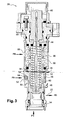
- This valve which is drawn in a vertical position in the figures 1 and 3 , essentially comprises a cylindrical body 30 whose open bottom end is connected to the outlet of the flow control means 16, and a piston 32 guided in sealed sliding inside the body 30 between a lower position, shown in FIG. figure 3 , closing the conduit 22 for supplying the injectors 18, and an upper position in which it opens the supply duct.
- the lower position of the piston 32 is defined by a seat 34 fixedly mounted in the open lower end of the body 30.
- the piston 32 is permanently returned to its lower position bearing on the seat 34 by a spring 36 mounted around the piston and bearing at its ends on an outer rim 38 of the upper part of the piston 32 and on a seat 40 mounted fixed to the upper end of the body 30.
- the seat 40 carries a central sensor 42, for example of the electromagnetic type, for detecting the axial position of a rod 44 connected to the piston 32.
- the piston 32 is of tubular cylindrical shape with a closed lower end and an open upper end, the rod 44 extending inside the piston 32 and being biased to bear against the bottom of the piston by a return spring 46 which is supported at its lower end on a flange 48 of the lower end of the rod 44 and which rests at its upper end on the seat 40 fixedly mounted to the upper end of the body 30, the spring 46 serving as the spring 36 to return the piston 32 to its lower position bearing on the seat 34.
- the first pressurization threshold is defined by applying inside the body 30 of the fuel pressure at the inlet of the pump 10, this pressure being applied by at least one orifice 50 formed in the part of the body 30 which is located above the piston 32 so that the pressure PB can act on the piston 32 regardless of the position thereof, to urge it down.
- the second pressurization threshold is defined by applying to the piston 32 the pressure of the fuel PH at the outlet of the pump 10, by means of an orifice 52 formed in the body 30 at a level lower than that of the orifice 50, so that this orifice 52 can be closed by the piston 32 when the latter is in its lower position, and open when the piston 32 is displaced upwards by the pressure P of the fuel at the outlet of the means 16 for adjusting the flow, the pressure PH of the fuel then acting on the piston 32 to urge it downwards, this pressure P being determined by the pressure in the feed pipe 22 of the injectors, by the pressure in the body 30 and by the flow rate of fuel supplied to the injectors.
- the orifice 52 comprises a cylindrical passage 54 which opens outside the body 30 and whose depth is less than the thickness of the body 30 at this point, an annular groove 56 which is formed in the internal cylindrical surface of the body 30 at the height of the passage 54, and a hole 58 of very small diameter which is formed in the thickness of material separating the passage 54 from the annular groove 56 and which makes them communicate with each other.
- the cylindrical wall of the piston 32 comprises at least one and preferably several radial openings 60 formed in the same transverse plane and distributed around the axis of the piston, which are formed in an annular groove of the outer peripheral surface of the piston and which are intended to be brought to the level of the annular groove 56 of the body 30 when the piston is displaced upwards by the pressure P of the fuel applied to the lower end of the body 30.
- the annular groove of the piston 32 in which the radial orifices 60 are formed is at a short axial distance from the annular groove 56 of the surface internal body 30.
- This axial distance defines the length of the first pressurization threshold.
- the level of the second pressurization threshold is defined by the diameter of the orifice 58 and the value of the injected fuel flow for which the transition between the two pressurization thresholds occurs is determined by the axial position of the orifice 58 in the body 30.
- the invention makes it possible to define two fuel pressurization thresholds, one for start-up and re-ignition, and the other for idling, with a simple and inexpensive modification of the pressurization and cut-off valve.
Landscapes
- Engineering & Computer Science (AREA)
- Chemical & Material Sciences (AREA)
- Combustion & Propulsion (AREA)
- Mechanical Engineering (AREA)
- General Engineering & Computer Science (AREA)
- Fuel-Injection Apparatus (AREA)
- Supercharger (AREA)
- Control Of Fluid Gearings (AREA)
- Details Of Reciprocating Pumps (AREA)
Applications Claiming Priority (1)
| Application Number | Priority Date | Filing Date | Title |
|---|---|---|---|
| FR0700386A FR2911634B1 (fr) | 2007-01-19 | 2007-01-19 | Dispositif d'injection de carburant dans une turbomachine |
Publications (2)
| Publication Number | Publication Date |
|---|---|
| EP1947385A1 true EP1947385A1 (de) | 2008-07-23 |
| EP1947385B1 EP1947385B1 (de) | 2009-02-25 |
Family
ID=38610090
Family Applications (1)
| Application Number | Title | Priority Date | Filing Date |
|---|---|---|---|
| EP20080290031 Active EP1947385B1 (de) | 2007-01-19 | 2008-01-15 | Vorrichtung zur Kraftstoffeinspritzung in eine Strömungsmaschine |
Country Status (17)
| Country | Link |
|---|---|
| US (1) | US8156742B2 (de) |
| EP (1) | EP1947385B1 (de) |
| JP (1) | JP5082158B2 (de) |
| CN (1) | CN101225966B (de) |
| AT (1) | ATE423947T1 (de) |
| BR (1) | BRPI0800041B8 (de) |
| CA (1) | CA2619352C (de) |
| DE (1) | DE602008000002D1 (de) |
| ES (1) | ES2320600T3 (de) |
| FR (1) | FR2911634B1 (de) |
| IL (1) | IL188867A (de) |
| MA (1) | MA29827B1 (de) |
| MX (1) | MX2008000917A (de) |
| RU (1) | RU2450145C2 (de) |
| SG (1) | SG144841A1 (de) |
| UA (1) | UA94413C2 (de) |
| ZA (1) | ZA200800556B (de) |
Families Citing this family (9)
| Publication number | Priority date | Publication date | Assignee | Title |
|---|---|---|---|---|
| CN102287268B (zh) * | 2011-08-05 | 2013-10-30 | 中国南方航空工业(集团)有限公司 | 状态转换活门及系统 |
| CN102493873B (zh) * | 2011-12-14 | 2014-04-23 | 中国人民解放军总参谋部第六十研究所 | 小型涡喷发动机燃油调节器 |
| FR2987429B1 (fr) * | 2012-02-24 | 2014-03-07 | Snecma | Injecteur de carburant pour une turbomachine |
| CN102980622B (zh) * | 2012-11-06 | 2015-06-17 | 中国航空工业集团公司沈阳发动机设计研究所 | 一种燃油计量装置起动流量特性设计及调整方法 |
| GB201400153D0 (en) * | 2014-01-06 | 2014-02-19 | Rolls Royce Controls & Data Services Ltd | Enfine fuel control system |
| FR3050789B1 (fr) * | 2016-05-02 | 2018-11-30 | Ge Energy Products France Snc | Vanne multi-voies |
| FR3055664B1 (fr) * | 2016-09-02 | 2020-05-01 | Safran Power Units | Unite de dosage de carburant pour turbomachine |
| CN107013339B (zh) * | 2017-05-28 | 2023-09-26 | 中国航发商用航空发动机有限责任公司 | 航空发动机燃油喷嘴用主燃级主油路活门及其使用方法 |
| FR3114617B1 (fr) | 2020-09-25 | 2022-09-30 | Safran Aircraft Engines | Clapet de surpression et circuit de carburant pour une turbomachine d’aeronef |
Citations (3)
| Publication number | Priority date | Publication date | Assignee | Title |
|---|---|---|---|---|
| FR2818690A1 (fr) * | 2000-12-22 | 2002-06-28 | Snecma Moteurs | Clapet de pressurisation a deux niveaux commande par un doseur de carburant |
| EP1557546A1 (de) * | 2004-01-21 | 2005-07-27 | Goodrich Control Systems Ltd | Kraftstoffzufuhrsystem |
| US20060021324A1 (en) * | 2004-08-02 | 2006-02-02 | Honeywell International, Inc. | System and method to reduce fuel system pumping heat input |
Family Cites Families (7)
| Publication number | Priority date | Publication date | Assignee | Title |
|---|---|---|---|---|
| US5020315A (en) * | 1989-08-08 | 1991-06-04 | United Technologies Corporation | Multiple function fuel valve and system |
| FR2711433B1 (fr) * | 1993-10-20 | 1995-12-01 | Snecma | Régulateur coaxial de débit. |
| US5636659A (en) * | 1995-10-17 | 1997-06-10 | Westinghouse Electric Corporation | Variable area compensation valve |
| US6328056B1 (en) * | 1997-12-12 | 2001-12-11 | Honeywell International Inc. | Proportional bypass valve with dual variable orifice |
| FR2817054A1 (fr) * | 2000-11-21 | 2002-05-24 | Snecma Moteurs | Dispositif doseur a reglage optimise |
| FR2825120B1 (fr) * | 2001-05-25 | 2003-12-12 | Snecma Moteurs | Doseur a 2 sorties integrees |
| RU2285140C2 (ru) * | 2004-04-20 | 2006-10-10 | ОАО "Научно-производственное предприятие "ЭГА" | Способ управления исполнительным механизмом дозатора топлива газотурбинного двигателя и система для его осуществления |
-
2007
- 2007-01-19 FR FR0700386A patent/FR2911634B1/fr not_active Expired - Fee Related
-
2008
- 2008-01-15 EP EP20080290031 patent/EP1947385B1/de active Active
- 2008-01-15 AT AT08290031T patent/ATE423947T1/de active
- 2008-01-15 DE DE200860000002 patent/DE602008000002D1/de active Active
- 2008-01-15 ES ES08290031T patent/ES2320600T3/es active Active
- 2008-01-16 CA CA2619352A patent/CA2619352C/fr active Active
- 2008-01-16 SG SG200800409-5A patent/SG144841A1/en unknown
- 2008-01-16 MA MA30575A patent/MA29827B1/fr unknown
- 2008-01-17 RU RU2008101904/06A patent/RU2450145C2/ru active
- 2008-01-17 IL IL188867A patent/IL188867A/en active IP Right Grant
- 2008-01-18 JP JP2008009075A patent/JP5082158B2/ja active Active
- 2008-01-18 MX MX2008000917A patent/MX2008000917A/es active IP Right Grant
- 2008-01-18 US US12/016,624 patent/US8156742B2/en active Active
- 2008-01-18 ZA ZA200800556A patent/ZA200800556B/xx unknown
- 2008-01-18 UA UAA200800638A patent/UA94413C2/ru unknown
- 2008-01-18 BR BRPI0800041-7 patent/BRPI0800041B8/pt active IP Right Grant
- 2008-01-21 CN CN2008100042371A patent/CN101225966B/zh active Active
Patent Citations (3)
| Publication number | Priority date | Publication date | Assignee | Title |
|---|---|---|---|---|
| FR2818690A1 (fr) * | 2000-12-22 | 2002-06-28 | Snecma Moteurs | Clapet de pressurisation a deux niveaux commande par un doseur de carburant |
| EP1557546A1 (de) * | 2004-01-21 | 2005-07-27 | Goodrich Control Systems Ltd | Kraftstoffzufuhrsystem |
| US20060021324A1 (en) * | 2004-08-02 | 2006-02-02 | Honeywell International, Inc. | System and method to reduce fuel system pumping heat input |
Also Published As
| Publication number | Publication date |
|---|---|
| RU2450145C2 (ru) | 2012-05-10 |
| MX2008000917A (es) | 2009-02-24 |
| ZA200800556B (en) | 2009-08-26 |
| CN101225966B (zh) | 2012-02-29 |
| ES2320600T3 (es) | 2009-05-25 |
| BRPI0800041B8 (pt) | 2019-12-10 |
| IL188867A (en) | 2011-10-31 |
| US8156742B2 (en) | 2012-04-17 |
| FR2911634B1 (fr) | 2009-03-06 |
| ATE423947T1 (de) | 2009-03-15 |
| CN101225966A (zh) | 2008-07-23 |
| US20080178596A1 (en) | 2008-07-31 |
| UA94413C2 (ru) | 2011-05-10 |
| BRPI0800041B1 (pt) | 2019-08-13 |
| CA2619352C (fr) | 2015-03-31 |
| RU2008101904A (ru) | 2009-07-27 |
| DE602008000002D1 (de) | 2009-04-09 |
| MA29827B1 (fr) | 2008-10-03 |
| JP2008175208A (ja) | 2008-07-31 |
| IL188867A0 (en) | 2008-11-03 |
| EP1947385B1 (de) | 2009-02-25 |
| SG144841A1 (en) | 2008-08-28 |
| BRPI0800041A (pt) | 2008-09-02 |
| CA2619352A1 (fr) | 2008-07-19 |
| FR2911634A1 (fr) | 2008-07-25 |
| JP5082158B2 (ja) | 2012-11-28 |
Similar Documents
| Publication | Publication Date | Title |
|---|---|---|
| EP1947385B1 (de) | Vorrichtung zur Kraftstoffeinspritzung in eine Strömungsmaschine | |
| EP0020249B1 (de) | Einspritzpumpe für Brennkraftmaschine | |
| EP2964933B1 (de) | Kompakte dosierungsvorrichtung für einen injektor mit zwei brennstoffkreisläufen für eine flugzeugturbomaschine | |
| EP2817498B1 (de) | Brennstoff-einspritzdüse für gasturbine | |
| FR2716936A1 (fr) | Circuit de distribution de carburant pour moteur à combustion interne. | |
| FR2824874A1 (fr) | Dispositif d'injection de carburant de moteur a combustion interne, notamment injecteur a rampe commune | |
| EP2006587B1 (de) | Dichtungsventilsystem | |
| CH641284A5 (fr) | Dispositif regulateur de la pression d'un fluide. | |
| FR3011619A1 (fr) | Injecteur de carburant pour une turbomachine | |
| EP1312864B1 (de) | Kraftstoffdosierungsvorrichtung für die Einspritzdüse einer Turbomaschine | |
| FR2463271A1 (fr) | Pompe d'injection de carburant pour moteurs a combustion interne | |
| FR2504203A1 (fr) | Pompe d'injection pour moteur a combustion interne comprenant un dispositif de reglage de l'instant de refoulement du combustible d'injection | |
| FR2718190A1 (fr) | Soupape de régulation d'injection de carburant pour une turbomachine. | |
| FR2485638A1 (fr) | Nouvel ensemble pompe-injecteur de combustible pour moteur a combustion interne | |
| FR2485637A1 (fr) | Ensemble pompe-injecteur de combustible pour moteur a combustion interne | |
| EP3025049B1 (de) | Kraftstoffeinspritzer | |
| FR2797917A1 (fr) | Dispositif d'injection pour moteur a combustion interne a injection directe | |
| FR2773593A1 (fr) | Systeme d'injection de carburant pour moteurs a combustion interne | |
| FR3122220A1 (fr) | Système d'alimentation en carburant liquide pour un moteur d’aéronef | |
| FR3115327A1 (fr) | Dispositif d’alimentation en carburant d’une turbomachine d’aeronef | |
| EP3732359A1 (de) | Verfahren zur steuerung der brennstoffzufuhr zu einer brennkammer einer turbinenmaschine, kraftstoffversorgungssystem und turbinenmotor | |
| FR2654468A1 (fr) | Soupape de pression pour installation d'injection, en particulier pour moteur a combustion interne. | |
| FR2478749A1 (fr) | Dispositif d'injection de combustible | |
| CH340092A (fr) | Pompe d'injection à piston | |
| CH343706A (fr) | Pompe à piston, notamment pour l'injection de combustible dans un moteur à combustion interne |
Legal Events
| Date | Code | Title | Description |
|---|---|---|---|
| PUAI | Public reference made under article 153(3) epc to a published international application that has entered the european phase |
Free format text: ORIGINAL CODE: 0009012 |
|
| AK | Designated contracting states |
Kind code of ref document: A1 Designated state(s): AT BE BG CH CY CZ DE DK EE ES FI FR GB GR HR HU IE IS IT LI LT LU LV MC MT NL NO PL PT RO SE SI SK TR |
|
| AX | Request for extension of the european patent |
Extension state: AL BA MK RS |
|
| 17P | Request for examination filed |
Effective date: 20080728 |
|
| GRAP | Despatch of communication of intention to grant a patent |
Free format text: ORIGINAL CODE: EPIDOSNIGR1 |
|
| GRAS | Grant fee paid |
Free format text: ORIGINAL CODE: EPIDOSNIGR3 |
|
| GRAA | (expected) grant |
Free format text: ORIGINAL CODE: 0009210 |
|
| AK | Designated contracting states |
Kind code of ref document: B1 Designated state(s): AT BE BG CH CY CZ DE DK EE ES FI FR GB GR HR HU IE IS IT LI LT LU LV MC MT NL NO PL PT RO SE SI SK TR |
|
| REG | Reference to a national code |
Ref country code: GB Ref legal event code: FG4D Free format text: NOT ENGLISH |
|
| REG | Reference to a national code |
Ref country code: CH Ref legal event code: EP Ref country code: CH Ref legal event code: NV Representative=s name: MICHELI & CIE SA |
|
| AKX | Designation fees paid |
Designated state(s): AT BE BG CH CY CZ DE DK EE ES FI FR GB GR HR HU IE IS IT LI LT LU LV MC MT NL NO PL PT RO SE SI SK TR |
|
| REG | Reference to a national code |
Ref country code: IE Ref legal event code: FG4D Free format text: LANGUAGE OF EP DOCUMENT: FRENCH |
|
| REG | Reference to a national code |
Ref country code: SE Ref legal event code: TRGR |
|
| REF | Corresponds to: |
Ref document number: 602008000002 Country of ref document: DE Date of ref document: 20090409 Kind code of ref document: P |
|
| REG | Reference to a national code |
Ref country code: ES Ref legal event code: FG2A Ref document number: 2320600 Country of ref document: ES Kind code of ref document: T3 |
|
| PG25 | Lapsed in a contracting state [announced via postgrant information from national office to epo] |
Ref country code: FI Free format text: LAPSE BECAUSE OF FAILURE TO SUBMIT A TRANSLATION OF THE DESCRIPTION OR TO PAY THE FEE WITHIN THE PRESCRIBED TIME-LIMIT Effective date: 20090225 Ref country code: LT Free format text: LAPSE BECAUSE OF FAILURE TO SUBMIT A TRANSLATION OF THE DESCRIPTION OR TO PAY THE FEE WITHIN THE PRESCRIBED TIME-LIMIT Effective date: 20090225 Ref country code: SI Free format text: LAPSE BECAUSE OF FAILURE TO SUBMIT A TRANSLATION OF THE DESCRIPTION OR TO PAY THE FEE WITHIN THE PRESCRIBED TIME-LIMIT Effective date: 20090225 |
|
| PG25 | Lapsed in a contracting state [announced via postgrant information from national office to epo] |
Ref country code: PL Free format text: LAPSE BECAUSE OF FAILURE TO SUBMIT A TRANSLATION OF THE DESCRIPTION OR TO PAY THE FEE WITHIN THE PRESCRIBED TIME-LIMIT Effective date: 20090225 Ref country code: IS Free format text: LAPSE BECAUSE OF FAILURE TO SUBMIT A TRANSLATION OF THE DESCRIPTION OR TO PAY THE FEE WITHIN THE PRESCRIBED TIME-LIMIT Effective date: 20090625 Ref country code: LV Free format text: LAPSE BECAUSE OF FAILURE TO SUBMIT A TRANSLATION OF THE DESCRIPTION OR TO PAY THE FEE WITHIN THE PRESCRIBED TIME-LIMIT Effective date: 20090225 |
|
| RAP2 | Party data changed (patent owner data changed or rights of a patent transferred) |
Owner name: SNECMA |
|
| REG | Reference to a national code |
Ref country code: IE Ref legal event code: FD4D |
|
| PG25 | Lapsed in a contracting state [announced via postgrant information from national office to epo] |
Ref country code: NO Free format text: LAPSE BECAUSE OF FAILURE TO SUBMIT A TRANSLATION OF THE DESCRIPTION OR TO PAY THE FEE WITHIN THE PRESCRIBED TIME-LIMIT Effective date: 20090525 |
|
| PG25 | Lapsed in a contracting state [announced via postgrant information from national office to epo] |
Ref country code: DK Free format text: LAPSE BECAUSE OF FAILURE TO SUBMIT A TRANSLATION OF THE DESCRIPTION OR TO PAY THE FEE WITHIN THE PRESCRIBED TIME-LIMIT Effective date: 20090225 Ref country code: CZ Free format text: LAPSE BECAUSE OF FAILURE TO SUBMIT A TRANSLATION OF THE DESCRIPTION OR TO PAY THE FEE WITHIN THE PRESCRIBED TIME-LIMIT Effective date: 20090225 Ref country code: IE Free format text: LAPSE BECAUSE OF FAILURE TO SUBMIT A TRANSLATION OF THE DESCRIPTION OR TO PAY THE FEE WITHIN THE PRESCRIBED TIME-LIMIT Effective date: 20090225 Ref country code: EE Free format text: LAPSE BECAUSE OF FAILURE TO SUBMIT A TRANSLATION OF THE DESCRIPTION OR TO PAY THE FEE WITHIN THE PRESCRIBED TIME-LIMIT Effective date: 20090225 |
|
| NLT2 | Nl: modifications (of names), taken from the european patent patent bulletin |
Owner name: SNECMA Effective date: 20090909 |
|
| PG25 | Lapsed in a contracting state [announced via postgrant information from national office to epo] |
Ref country code: SK Free format text: LAPSE BECAUSE OF FAILURE TO SUBMIT A TRANSLATION OF THE DESCRIPTION OR TO PAY THE FEE WITHIN THE PRESCRIBED TIME-LIMIT Effective date: 20090225 Ref country code: RO Free format text: LAPSE BECAUSE OF FAILURE TO SUBMIT A TRANSLATION OF THE DESCRIPTION OR TO PAY THE FEE WITHIN THE PRESCRIBED TIME-LIMIT Effective date: 20090225 |
|
| PLBE | No opposition filed within time limit |
Free format text: ORIGINAL CODE: 0009261 |
|
| STAA | Information on the status of an ep patent application or granted ep patent |
Free format text: STATUS: NO OPPOSITION FILED WITHIN TIME LIMIT |
|
| PG25 | Lapsed in a contracting state [announced via postgrant information from national office to epo] |
Ref country code: BG Free format text: LAPSE BECAUSE OF FAILURE TO SUBMIT A TRANSLATION OF THE DESCRIPTION OR TO PAY THE FEE WITHIN THE PRESCRIBED TIME-LIMIT Effective date: 20090525 |
|
| 26N | No opposition filed |
Effective date: 20091126 |
|
| PG25 | Lapsed in a contracting state [announced via postgrant information from national office to epo] |
Ref country code: HR Free format text: LAPSE BECAUSE OF FAILURE TO SUBMIT A TRANSLATION OF THE DESCRIPTION OR TO PAY THE FEE WITHIN THE PRESCRIBED TIME-LIMIT Effective date: 20090225 |
|
| PG25 | Lapsed in a contracting state [announced via postgrant information from national office to epo] |
Ref country code: MC Free format text: LAPSE BECAUSE OF NON-PAYMENT OF DUE FEES Effective date: 20100131 |
|
| PG25 | Lapsed in a contracting state [announced via postgrant information from national office to epo] |
Ref country code: GR Free format text: LAPSE BECAUSE OF FAILURE TO SUBMIT A TRANSLATION OF THE DESCRIPTION OR TO PAY THE FEE WITHIN THE PRESCRIBED TIME-LIMIT Effective date: 20090526 |
|
| REG | Reference to a national code |
Ref country code: GB Ref legal event code: 732E Free format text: REGISTERED BETWEEN 20120419 AND 20120425 |
|
| PG25 | Lapsed in a contracting state [announced via postgrant information from national office to epo] |
Ref country code: CY Free format text: LAPSE BECAUSE OF FAILURE TO SUBMIT A TRANSLATION OF THE DESCRIPTION OR TO PAY THE FEE WITHIN THE PRESCRIBED TIME-LIMIT Effective date: 20090225 |
|
| PG25 | Lapsed in a contracting state [announced via postgrant information from national office to epo] |
Ref country code: HU Free format text: LAPSE BECAUSE OF FAILURE TO SUBMIT A TRANSLATION OF THE DESCRIPTION OR TO PAY THE FEE WITHIN THE PRESCRIBED TIME-LIMIT Effective date: 20090826 Ref country code: PT Free format text: LAPSE BECAUSE OF FAILURE TO SUBMIT A TRANSLATION OF THE DESCRIPTION OR TO PAY THE FEE WITHIN THE PRESCRIBED TIME-LIMIT Effective date: 20090725 Ref country code: LU Free format text: LAPSE BECAUSE OF NON-PAYMENT OF DUE FEES Effective date: 20100115 |
|
| REG | Reference to a national code |
Ref country code: DE Ref legal event code: R082 Ref document number: 602008000002 Country of ref document: DE Representative=s name: MITSCHERLICH & PARTNER PATENT- UND RECHTSANWAE, DE |
|
| PG25 | Lapsed in a contracting state [announced via postgrant information from national office to epo] |
Ref country code: TR Free format text: LAPSE BECAUSE OF FAILURE TO SUBMIT A TRANSLATION OF THE DESCRIPTION OR TO PAY THE FEE WITHIN THE PRESCRIBED TIME-LIMIT Effective date: 20090225 |
|
| REG | Reference to a national code |
Ref country code: DE Ref legal event code: R081 Ref document number: 602008000002 Country of ref document: DE Owner name: SNECMA, FR Free format text: FORMER OWNER: HISPANO SUIZA, COLOMBES, FR Effective date: 20121005 Ref country code: DE Ref legal event code: R082 Ref document number: 602008000002 Country of ref document: DE Representative=s name: MITSCHERLICH & PARTNER PATENT- UND RECHTSANWAE, DE Effective date: 20121005 Ref country code: DE Ref legal event code: R082 Ref document number: 602008000002 Country of ref document: DE Representative=s name: MITSCHERLICH, PATENT- UND RECHTSANWAELTE PARTM, DE Effective date: 20121005 Ref country code: DE Ref legal event code: R082 Ref document number: 602008000002 Country of ref document: DE Representative=s name: MITSCHERLICH, PATENT- UND RECHTSANWAELTE, PART, DE Effective date: 20121005 |
|
| PGFP | Annual fee paid to national office [announced via postgrant information from national office to epo] |
Ref country code: ES Payment date: 20130109 Year of fee payment: 6 |
|
| REG | Reference to a national code |
Ref country code: ES Ref legal event code: FD2A Effective date: 20150701 |
|
| PG25 | Lapsed in a contracting state [announced via postgrant information from national office to epo] |
Ref country code: ES Free format text: LAPSE BECAUSE OF NON-PAYMENT OF DUE FEES Effective date: 20140116 |
|
| REG | Reference to a national code |
Ref country code: FR Ref legal event code: PLFP Year of fee payment: 9 |
|
| REG | Reference to a national code |
Ref country code: FR Ref legal event code: PLFP Year of fee payment: 10 |
|
| REG | Reference to a national code |
Ref country code: FR Ref legal event code: PLFP Year of fee payment: 11 |
|
| REG | Reference to a national code |
Ref country code: FR Ref legal event code: CD Owner name: SAFRAN AIRCRAFT ENGINES, FR Effective date: 20170717 |
|
| PGFP | Annual fee paid to national office [announced via postgrant information from national office to epo] |
Ref country code: GB Payment date: 20231219 Year of fee payment: 17 |
|
| PGFP | Annual fee paid to national office [announced via postgrant information from national office to epo] |
Ref country code: SE Payment date: 20231219 Year of fee payment: 17 Ref country code: NL Payment date: 20231219 Year of fee payment: 17 Ref country code: FR Payment date: 20231219 Year of fee payment: 17 |
|
| PGFP | Annual fee paid to national office [announced via postgrant information from national office to epo] |
Ref country code: BE Payment date: 20231219 Year of fee payment: 17 |
|
| PGFP | Annual fee paid to national office [announced via postgrant information from national office to epo] |
Ref country code: AT Payment date: 20231222 Year of fee payment: 17 |
|
| PGFP | Annual fee paid to national office [announced via postgrant information from national office to epo] |
Ref country code: DE Payment date: 20231219 Year of fee payment: 17 Ref country code: CH Payment date: 20240202 Year of fee payment: 17 |
|
| PGFP | Annual fee paid to national office [announced via postgrant information from national office to epo] |
Ref country code: IT Payment date: 20240102 Year of fee payment: 17 |