EP1947296A2 - Turbine blade with reserve cooling air film hole direction - Google Patents
Turbine blade with reserve cooling air film hole direction Download PDFInfo
- Publication number
- EP1947296A2 EP1947296A2 EP08250077A EP08250077A EP1947296A2 EP 1947296 A2 EP1947296 A2 EP 1947296A2 EP 08250077 A EP08250077 A EP 08250077A EP 08250077 A EP08250077 A EP 08250077A EP 1947296 A2 EP1947296 A2 EP 1947296A2
- Authority
- EP
- European Patent Office
- Prior art keywords
- section
- film cooling
- cooling holes
- meter
- diffused
- Prior art date
- Legal status (The legal status is an assumption and is not a legal conclusion. Google has not performed a legal analysis and makes no representation as to the accuracy of the status listed.)
- Granted
Links
Images


Classifications
-
- F—MECHANICAL ENGINEERING; LIGHTING; HEATING; WEAPONS; BLASTING
- F01—MACHINES OR ENGINES IN GENERAL; ENGINE PLANTS IN GENERAL; STEAM ENGINES
- F01D—NON-POSITIVE DISPLACEMENT MACHINES OR ENGINES, e.g. STEAM TURBINES
- F01D5/00—Blades; Blade-carrying members; Heating, heat-insulating, cooling or antivibration means on the blades or the members
- F01D5/12—Blades
- F01D5/14—Form or construction
- F01D5/18—Hollow blades, i.e. blades with cooling or heating channels or cavities; Heating, heat-insulating or cooling means on blades
- F01D5/186—Film cooling
-
- F—MECHANICAL ENGINEERING; LIGHTING; HEATING; WEAPONS; BLASTING
- F05—INDEXING SCHEMES RELATING TO ENGINES OR PUMPS IN VARIOUS SUBCLASSES OF CLASSES F01-F04
- F05D—INDEXING SCHEME FOR ASPECTS RELATING TO NON-POSITIVE-DISPLACEMENT MACHINES OR ENGINES, GAS-TURBINES OR JET-PROPULSION PLANTS
- F05D2250/00—Geometry
- F05D2250/50—Inlet or outlet
- F05D2250/52—Outlet
Definitions
- This application relates to a turbine blade, wherein the meter sections of film cooling holes extend at an angle and in a direction toward a blade root from the blade tip.
- a diffused section of a film cooling hole extends toward the blade tip from a meter section to receive air driven by centrifugal force.
- Gas turbine engines are known, and include a plurality of sections which are typically mounted in series. Typically a fan delivers air to a compressor. Air is compressed in the compressor and delivered downstream to be mixed with fuel and combusted in a combustor section. Products of combustion move downstream over turbine rotors.
- the turbine rotors include a plurality of removable blades which rotate with the rotors, and are driven by the products of combustion. The turbine rotors drive components within the gas turbine engine, including the fan and compressor.
- the turbine blades become quite hot from the products of combustion.
- air is passed outwardly through holes on an outer face of an airfoil of the turbine blade, such that the cool air passes along the outer face.
- film cooling holes are designed to maximize the coverage surface area on the blade, which receives the air and also to maximize the time cooling air is kept on a face of the blade.
- the film cooling holes have a meter section that typically extend at an angle to the outer face.
- the angle includes a major component in a direction extending from a blade root and toward a blade tip.
- a diffused section extends back from this meter section towards the blade root.
- This type of film cooling holes is known as shaped or flared holes.
- the purpose of the diffused section is to slow the speed of the cooling air down as it reaches the face of the blade, such that the air would be less likely to move away from the face, and more likely to move along the face.
- the meter section of film cooling holes in a turbine blade extends with a major component in a direction from the blade tip toward the blade root.
- a diffused section is formed to enlarge a film cooling hole at the outer face of the blade. The diffused section extends toward the blade tip from the meter section.
- a gas turbine engine 10 circumferentially disposed about an engine centerline, or axial centerline axis 12 is shown in Figure 1 .
- the engine 10 includes a fan 14, a compressor 16, a combustion section 18 and a turbine 11.
- air compressed in the compressor 16 is mixed with fuel and burned in the combustion section 18 and expanded in turbine 11.
- the turbine 11 includes rotors 22 which rotate in response to the expansion, driving the compressor 16 and fan 14.
- the turbine 11 comprises alternating rows of rotary airfoils or blades 24 and static airfoils or vanes 26. In fact, this view is quite schematic, and blades 24 and vanes 26 are actually removable. It should be understood that this view is included simply to provide a basic understanding of the sections in a gas turbine engine, and not to limit the invention. This invention extends to all types of turbine engines for all applications.
- Figure 2A shows a prior art turbine blade 24.
- a platform 32 and blade root form a base for an airfoil 34.
- the airfoil 34 includes a plurality of film cooling holes 36.
- the film cooling holes 36 have a meter section 38, and a diffused section 40.
- the meter section 38 extends along a non-parallel angle relative to a radial axis, and with a component extending from the blade root to the blade tip.
- the air from an internal cooling passage 42 passes through this meter section 38 to an outer face of the airfoil 34.
- this diffused section extends from the meter section 38 and closer to the blade root than the blade tip.
- a meter section 52 extends with a main component of its direction from the blade tip to the blade root.
- a diffused section 54 extends toward the blade tip from the meter section 52.
- the diffused section 54 may be at an angle having a lesser component in the direction from the tip towards the root.
- the enlarged portions 40 and 54 may not extend directly, or solely, towards the root and tip respectively. Still, they extend with a major component in those directions.
- the present invention ensures the cooling air is delivered to the outer face 51 across the entirety of the film cooling holes.
- the diffused sections 40 and 54 may not extend directly, or solely, towards the root and tip respectively. Still, they extend with a major component in those directions. It should be noted that the flow in the internal cooling passage 42 can flow in any direction and does not necessarily have to flow from blade root to blade tip.
- the meter section can extend in the reverse direction or any direction with the diffused section extending toward the tip. Flow momentum will still fill the meter section while centrifugal force will fill the diffused section.
Landscapes
- Engineering & Computer Science (AREA)
- Mechanical Engineering (AREA)
- General Engineering & Computer Science (AREA)
- Turbine Rotor Nozzle Sealing (AREA)
Abstract
Description
- This application relates to a turbine blade, wherein the meter sections of film cooling holes extend at an angle and in a direction toward a blade root from the blade tip. In addition, a diffused section of a film cooling hole extends toward the blade tip from a meter section to receive air driven by centrifugal force.
- Gas turbine engines are known, and include a plurality of sections which are typically mounted in series. Typically a fan delivers air to a compressor. Air is compressed in the compressor and delivered downstream to be mixed with fuel and combusted in a combustor section. Products of combustion move downstream over turbine rotors. The turbine rotors include a plurality of removable blades which rotate with the rotors, and are driven by the products of combustion. The turbine rotors drive components within the gas turbine engine, including the fan and compressor.
- The turbine blades become quite hot from the products of combustion. Thus, it is known to pass cooling air through internal cooling passages within the turbine blades. In one known cooling technique, air is passed outwardly through holes on an outer face of an airfoil of the turbine blade, such that the cool air passes along the outer face. These film cooling holes are designed to maximize the coverage surface area on the blade, which receives the air and also to maximize the time cooling air is kept on a face of the blade.
- In the prior art, the film cooling holes have a meter section that typically extend at an angle to the outer face. The angle includes a major component in a direction extending from a blade root and toward a blade tip. In addition, a diffused section extends back from this meter section towards the blade root. This type of film cooling holes is known as shaped or flared holes. The purpose of the diffused section is to slow the speed of the cooling air down as it reaches the face of the blade, such that the air would be less likely to move away from the face, and more likely to move along the face.
- However, in the prior art, a centrifugal force applied as the blade rotates, moves the cooling air radially outwardly and toward the blade tip. Thus, the diffused section tends not to be filled with air. This centrifugal force and flow momentum drives the air into the radially outer portions of the holes spaced toward the tip, and leaves the diffused section less filled. Thus, the air exits the film cooling hole at a greater velocity, and does not stay on the face of the blade as long as would be desired.
- In a disclosed embodiment of this invention, the meter section of film cooling holes in a turbine blade extends with a major component in a direction from the blade tip toward the blade root. A diffused section is formed to enlarge a film cooling hole at the outer face of the blade. The diffused section extends toward the blade tip from the meter section.
- As the blade rotates, and cooling air exits the film cooling hole, centrifugal force forces some of the cooling air into the diffused section and the diffused section is relatively full compared to the prior art. Thus, the air exits the film cooling hole at a lower velocity than in the prior art, tends to stay on the face of the turbine blade longer, and cover a greater surface area.
- These and other features of the present invention can be best understood from the following specification and drawings, the following of which is a brief description.
-
-
Figure 1 is a schematic view of a gas turbine engine. -
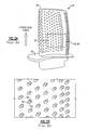
Figure 2A is a view of a prior art turbine blade. -
Figure 2B is an enlarged view of a portion of theFigure 2A turbine blade. -
Figure 2C is another view of theFigure 2A blade. -
Figure 3 is a view similar toFigure 2C , but showing the inventive blade. - A
gas turbine engine 10 circumferentially disposed about an engine centerline, oraxial centerline axis 12 is shown inFigure 1 . Theengine 10 includes afan 14, acompressor 16, acombustion section 18 and aturbine 11. As is well known in the art, air compressed in thecompressor 16 is mixed with fuel and burned in thecombustion section 18 and expanded inturbine 11. Theturbine 11 includesrotors 22 which rotate in response to the expansion, driving thecompressor 16 andfan 14. Theturbine 11 comprises alternating rows of rotary airfoils orblades 24 and static airfoils orvanes 26. In fact, this view is quite schematic, andblades 24 andvanes 26 are actually removable. It should be understood that this view is included simply to provide a basic understanding of the sections in a gas turbine engine, and not to limit the invention. This invention extends to all types of turbine engines for all applications. -
Figure 2A shows a priorart turbine blade 24. As known, aplatform 32 and blade root form a base for anairfoil 34. Theairfoil 34 includes a plurality offilm cooling holes 36. - As shown in
Figure 2B , thefilm cooling holes 36 have ameter section 38, and a diffusedsection 40. - As shown in
Figure 2C , themeter section 38 extends along a non-parallel angle relative to a radial axis, and with a component extending from the blade root to the blade tip. The air from aninternal cooling passage 42 passes through thismeter section 38 to an outer face of theairfoil 34. As can be seen inFigure 2C , this diffused section extends from themeter section 38 and closer to the blade root than the blade tip. Now, as theturbine blade 24 rotates, centrifugal forces force air from themeter section 38 radially outwardly, and away from the diffusedsection 40. Thus, the diffusedsection 40 is not always filled. - As shown in
Figure 3 , in aninventive turbine blade 50, ameter section 52 extends with a main component of its direction from the blade tip to the blade root. Adiffused section 54 extends toward the blade tip from themeter section 52. As can be seen, thediffused section 54 may be at an angle having a lesser component in the direction from the tip towards the root. As can be appreciated fromFigure 2 , the enlargedportions - When centrifugal force acts on the air in the
meter section 52, the air is driven into thediffused section 54. Flow momentum will ensure that themeter section 52 is still full. Thus, the present invention ensures the cooling air is delivered to the outer face 51 across the entirety of the film cooling holes. As can be appreciated fromFigure 2B , thediffused sections internal cooling passage 42 can flow in any direction and does not necessarily have to flow from blade root to blade tip. - In fact, the meter section can extend in the reverse direction or any direction with the diffused section extending toward the tip. Flow momentum will still fill the meter section while centrifugal force will fill the diffused section.
- Although a preferred embodiment of this invention has been disclosed, a worker of ordinary skill in this art would recognize that certain modifications would come within the scope of this invention. For that reason, the following claims should be studied to determine the true scope and content of this invention.
Claims (6)
- A turbine blade (50) comprising:a root, and an airfoil (34) extending away from the root to a tip;a plurality of film cooling holes (36) on an outer face of the airfoil (34), said airfoil (34) having at least one internal cooling passage (42) for receiving air from a source, and delivering air to said film cooling holes (36); andsaid film cooling holes receiving air from said cooling passage (42) through meter sections (52) extending with a component in a direction from the tip towards the root.
- The turbine blade as set forth in Claim 1, wherein a diffused section (54) of an outer end of said film cooling holes (36) extends towards said tip from said meter section (52).
- The turbine blade as set forth in Claim 2, wherein said diffused section (54) is formed along an angle having a lesser component in the direction from said tip toward said root than said meter section (52).
- A turbine blade (50) comprising:a root, and an airfoil (34) extending away from the root toward a tip;a plurality of film cooling holes (36) on an outer face of said airfoil (34), said airfoil (34) having at least one internal cooling passage (42) for receiving air from a source, and delivering air to said film cooling holes (36); andsaid film cooling holes (36) receiving air from said internal cooling passage (42) through meter sections (52), and an diffused section (54) of an outer end of said film cooling holes (36) communicates with said meter section (52), said diffused section (54) extending towards said tip from said meter section.
- The turbine blade as set forth in Claim 4, wherein said diffused section (54) is formed along an angle having a lesser component in the direction from said tip toward said root than said meter section (52).
- A gas turbine engine (10) comprising:a compressor section (16);a combustor section (18); anda turbine section (11), said turbine section including a rotor (22) mounting a plurality of turbine blades (50) as claimed in any preceding claim.
Applications Claiming Priority (1)
| Application Number | Priority Date | Filing Date | Title |
|---|---|---|---|
| US11/651,226 US7712316B2 (en) | 2007-01-09 | 2007-01-09 | Turbine blade with reverse cooling air film hole direction |
Publications (3)
| Publication Number | Publication Date |
|---|---|
| EP1947296A2 true EP1947296A2 (en) | 2008-07-23 |
| EP1947296A3 EP1947296A3 (en) | 2014-01-15 |
| EP1947296B1 EP1947296B1 (en) | 2015-02-25 |
Family
ID=39267819
Family Applications (1)
| Application Number | Title | Priority Date | Filing Date |
|---|---|---|---|
| EP08250077.8A Active EP1947296B1 (en) | 2007-01-09 | 2008-01-08 | Turbine blade with reserve cooling air film hole direction |
Country Status (2)
| Country | Link |
|---|---|
| US (2) | US7712316B2 (en) |
| EP (1) | EP1947296B1 (en) |
Cited By (3)
| Publication number | Priority date | Publication date | Assignee | Title |
|---|---|---|---|---|
| EP2131011A3 (en) * | 2008-06-05 | 2012-08-29 | United Technologies Corporation | Particle resistant in-wall cooling passage inlet |
| WO2013122910A1 (en) * | 2012-02-15 | 2013-08-22 | United Technologies Corporation | Multi-lobed cooling hole |
| EP3255248A1 (en) * | 2016-04-14 | 2017-12-13 | General Electric Company | Engine component for a turbine engine |
Families Citing this family (25)
| Publication number | Priority date | Publication date | Assignee | Title |
|---|---|---|---|---|
| US8210814B2 (en) * | 2008-06-18 | 2012-07-03 | General Electric Company | Crossflow turbine airfoil |
| US8079810B2 (en) * | 2008-09-16 | 2011-12-20 | Siemens Energy, Inc. | Turbine airfoil cooling system with divergent film cooling hole |
| US8245519B1 (en) * | 2008-11-25 | 2012-08-21 | Florida Turbine Technologies, Inc. | Laser shaped film cooling hole |
| US9121290B2 (en) * | 2010-05-06 | 2015-09-01 | United Technologies Corporation | Turbine airfoil with body microcircuits terminating in platform |
| US9157328B2 (en) * | 2010-12-24 | 2015-10-13 | Rolls-Royce North American Technologies, Inc. | Cooled gas turbine engine component |
| US8533949B2 (en) * | 2011-02-14 | 2013-09-17 | General Electric Company | Methods of manufacture for components with cooling channels |
| US20130156602A1 (en) * | 2011-12-16 | 2013-06-20 | United Technologies Corporation | Film cooled turbine component |
| WO2014186006A2 (en) | 2013-02-15 | 2014-11-20 | United Technologies Corporation | Cooling hole for a gas turbine engine component |
| US9371776B2 (en) | 2013-08-20 | 2016-06-21 | Darren Levine | Dual flow air injection intraturbine engine and method of operating same |
| US9416662B2 (en) * | 2013-09-03 | 2016-08-16 | General Electric Company | Method and system for providing cooling for turbine components |
| CN104281751B (en) * | 2014-10-14 | 2017-05-31 | 北京航空航天大学 | Turbine cooling blade parametrization constructing system and the method for a kind of feature based |
| US10036259B2 (en) | 2014-11-03 | 2018-07-31 | United Technologies Corporation | Turbine blade having film cooling hole arrangement |
| CN104392027B (en) * | 2014-11-10 | 2017-07-28 | 西北工业大学 | A kind of parametric modeling method of turbo blade turbulence columns |
| US10443434B2 (en) | 2014-12-08 | 2019-10-15 | United Technologies Corporation | Turbine airfoil platform segment with film cooling hole arrangement |
| US10301966B2 (en) | 2014-12-08 | 2019-05-28 | United Technologies Corporation | Turbine airfoil platform segment with film cooling hole arrangement |
| US10107140B2 (en) | 2014-12-08 | 2018-10-23 | United Technologies Corporation | Turbine airfoil segment having film cooling hole arrangement |
| US10060268B2 (en) | 2014-12-17 | 2018-08-28 | United Technologies Corporation | Turbine blade having film cooling hole arrangement |
| CN104598684B (en) * | 2015-01-19 | 2017-07-18 | 西北工业大学 | A kind of air film hole parametric modeling method |
| US20160298545A1 (en) * | 2015-04-13 | 2016-10-13 | General Electric Company | Turbine airfoil |
| US20170234142A1 (en) * | 2016-02-17 | 2017-08-17 | General Electric Company | Rotor Blade Trailing Edge Cooling |
| US10731469B2 (en) | 2016-05-16 | 2020-08-04 | Raytheon Technologies Corporation | Method and apparatus to enhance laminar flow for gas turbine engine components |
| CN111706409B (en) * | 2020-06-25 | 2022-11-01 | 中国民航大学 | A corrugated air film hole with branch holes |
| US11898460B2 (en) | 2022-06-09 | 2024-02-13 | General Electric Company | Turbine engine with a blade |
| US11927111B2 (en) | 2022-06-09 | 2024-03-12 | General Electric Company | Turbine engine with a blade |
| CN117226614B (en) * | 2023-11-14 | 2024-01-12 | 中国航发沈阳黎明航空发动机有限责任公司 | Method for polishing air film holes of double-wall turbine blade of aero-engine |
Family Cites Families (14)
| Publication number | Priority date | Publication date | Assignee | Title |
|---|---|---|---|---|
| US3819295A (en) * | 1972-09-21 | 1974-06-25 | Gen Electric | Cooling slot for airfoil blade |
| US4384823A (en) * | 1980-10-27 | 1983-05-24 | The United States Of America As Represented By The Administrator Of The National Aeronautics And Space Administration | Curved film cooling admission tube |
| US4653983A (en) | 1985-12-23 | 1987-03-31 | United Technologies Corporation | Cross-flow film cooling passages |
| GB2227965B (en) * | 1988-10-12 | 1993-02-10 | Rolls Royce Plc | Apparatus for drilling a shaped hole in a workpiece |
| US5340278A (en) * | 1992-11-24 | 1994-08-23 | United Technologies Corporation | Rotor blade with integral platform and a fillet cooling passage |
| US5419681A (en) * | 1993-01-25 | 1995-05-30 | General Electric Company | Film cooled wall |
| US5503529A (en) * | 1994-12-08 | 1996-04-02 | General Electric Company | Turbine blade having angled ejection slot |
| US5498133A (en) * | 1995-06-06 | 1996-03-12 | General Electric Company | Pressure regulated film cooling |
| US6092982A (en) * | 1996-05-28 | 2000-07-25 | Kabushiki Kaisha Toshiba | Cooling system for a main body used in a gas stream |
| US6164913A (en) * | 1999-07-26 | 2000-12-26 | General Electric Company | Dust resistant airfoil cooling |
| US6234755B1 (en) * | 1999-10-04 | 2001-05-22 | General Electric Company | Method for improving the cooling effectiveness of a gaseous coolant stream, and related articles of manufacture |
| GB2401915B (en) * | 2003-05-23 | 2006-06-14 | Rolls Royce Plc | Turbine blade |
| US20080152475A1 (en) * | 2006-12-21 | 2008-06-26 | Jack Raul Zausner | Method for preventing backflow and forming a cooling layer in an airfoil |
| US7621718B1 (en) * | 2007-03-28 | 2009-11-24 | Florida Turbine Technologies, Inc. | Turbine vane with leading edge fillet region impingement cooling |
-
2007
- 2007-01-09 US US11/651,226 patent/US7712316B2/en active Active
-
2008
- 2008-01-08 EP EP08250077.8A patent/EP1947296B1/en active Active
-
2010
- 2010-02-17 US US12/706,777 patent/US20100143132A1/en not_active Abandoned
Cited By (4)
| Publication number | Priority date | Publication date | Assignee | Title |
|---|---|---|---|---|
| EP2131011A3 (en) * | 2008-06-05 | 2012-08-29 | United Technologies Corporation | Particle resistant in-wall cooling passage inlet |
| WO2013122910A1 (en) * | 2012-02-15 | 2013-08-22 | United Technologies Corporation | Multi-lobed cooling hole |
| US8763402B2 (en) | 2012-02-15 | 2014-07-01 | United Technologies Corporation | Multi-lobed cooling hole and method of manufacture |
| EP3255248A1 (en) * | 2016-04-14 | 2017-12-13 | General Electric Company | Engine component for a turbine engine |
Also Published As
| Publication number | Publication date |
|---|---|
| EP1947296A3 (en) | 2014-01-15 |
| US20080163604A1 (en) | 2008-07-10 |
| EP1947296B1 (en) | 2015-02-25 |
| US7712316B2 (en) | 2010-05-11 |
| US20100143132A1 (en) | 2010-06-10 |
Similar Documents
| Publication | Publication Date | Title |
|---|---|---|
| EP1947296B1 (en) | Turbine blade with reserve cooling air film hole direction | |
| US7452186B2 (en) | Turbine blade including revised trailing edge cooling | |
| EP2230382B1 (en) | Gas turbine rotor stage | |
| EP3108107B1 (en) | Turbofan engine with geared architecture and lpc airfoils | |
| EP2204535A2 (en) | Turbine blade platform contours | |
| WO2014099634A2 (en) | Lightweight shrouded fan blade | |
| EP3656979B1 (en) | Aerofoil with stagnation zone cooling | |
| US20160208620A1 (en) | Gas turbine engine airfoil turbulator for airfoil creep resistance | |
| EP3094823B1 (en) | Gas turbine engine component and corresponding gas turbine engine | |
| WO2014159800A1 (en) | Obtuse angle chevron trip strip | |
| EP2960433B1 (en) | Gas turbine engine airfoil comprising angled cooling passages in the leading edge | |
| US11473434B2 (en) | Gas turbine engine airfoil | |
| EP3699406A1 (en) | Component for fastening arrangement, fastening arrangement and gas turbine engine comprising fastening arrangement | |
| US11015464B2 (en) | Conformal seal and vane bow wave cooling | |
| EP3450692B1 (en) | Seal assembly for the interface between combustor and vane | |
| EP3047102B1 (en) | Gas turbine engine with disk having periphery with protrusions | |
| EP3023596B1 (en) | Internally cooled turbine platform | |
| EP3489465B1 (en) | Seal for a vane seal system and method for managing damping in a vane seal system | |
| US11073035B2 (en) | Labyrinth sealing system and gas turbine engine with a labyrinth sealing system | |
| EP3108112B1 (en) | Turbofan engine with geared architecture and lpc airfoils | |
| US10119410B2 (en) | Vane seal system having spring positively locating seal member in axial direction | |
| EP3392472B1 (en) | Compressor section for a gas turbine engine, corresponding gas turbine engine and method of operating a compressor section in a gas turbine engine |
Legal Events
| Date | Code | Title | Description |
|---|---|---|---|
| PUAI | Public reference made under article 153(3) epc to a published international application that has entered the european phase |
Free format text: ORIGINAL CODE: 0009012 |
|
| AK | Designated contracting states |
Kind code of ref document: A2 Designated state(s): AT BE BG CH CY CZ DE DK EE ES FI FR GB GR HR HU IE IS IT LI LT LU LV MC MT NL NO PL PT RO SE SI SK TR |
|
| AX | Request for extension of the european patent |
Extension state: AL BA MK RS |
|
| PUAL | Search report despatched |
Free format text: ORIGINAL CODE: 0009013 |
|
| AK | Designated contracting states |
Kind code of ref document: A3 Designated state(s): AT BE BG CH CY CZ DE DK EE ES FI FR GB GR HR HU IE IS IT LI LT LU LV MC MT NL NO PL PT RO SE SI SK TR |
|
| AX | Request for extension of the european patent |
Extension state: AL BA MK RS |
|
| RIC1 | Information provided on ipc code assigned before grant |
Ipc: F01D 5/18 20060101AFI20131210BHEP |
|
| 17P | Request for examination filed |
Effective date: 20140715 |
|
| RBV | Designated contracting states (corrected) |
Designated state(s): AT BE BG CH CY CZ DE DK EE ES FI FR GB GR HR HU IE IS IT LI LT LU LV MC MT NL NO PL PT RO SE SI SK TR |
|
| GRAP | Despatch of communication of intention to grant a patent |
Free format text: ORIGINAL CODE: EPIDOSNIGR1 |
|
| INTG | Intention to grant announced |
Effective date: 20140822 |
|
| RBV | Designated contracting states (corrected) |
Designated state(s): DE GB |
|
| GRAS | Grant fee paid |
Free format text: ORIGINAL CODE: EPIDOSNIGR3 |
|
| GRAA | (expected) grant |
Free format text: ORIGINAL CODE: 0009210 |
|
| AK | Designated contracting states |
Kind code of ref document: B1 Designated state(s): DE GB |
|
| REG | Reference to a national code |
Ref country code: GB Ref legal event code: FG4D |
|
| REG | Reference to a national code |
Ref country code: DE Ref legal event code: R096 Ref document number: 602008036770 Country of ref document: DE Effective date: 20150409 |
|
| REG | Reference to a national code |
Ref country code: DE Ref legal event code: R097 Ref document number: 602008036770 Country of ref document: DE |
|
| PLBE | No opposition filed within time limit |
Free format text: ORIGINAL CODE: 0009261 |
|
| STAA | Information on the status of an ep patent application or granted ep patent |
Free format text: STATUS: NO OPPOSITION FILED WITHIN TIME LIMIT |
|
| 26N | No opposition filed |
Effective date: 20151126 |
|
| REG | Reference to a national code |
Ref country code: DE Ref legal event code: R082 Ref document number: 602008036770 Country of ref document: DE Representative=s name: SCHMITT-NILSON SCHRAUD WAIBEL WOHLFROM PATENTA, DE |
|
| REG | Reference to a national code |
Ref country code: DE Ref legal event code: R082 Ref document number: 602008036770 Country of ref document: DE Representative=s name: SCHMITT-NILSON SCHRAUD WAIBEL WOHLFROM PATENTA, DE Ref country code: DE Ref legal event code: R081 Ref document number: 602008036770 Country of ref document: DE Owner name: UNITED TECHNOLOGIES CORP. (N.D.GES.D. STAATES , US Free format text: FORMER OWNER: UNITED TECHNOLOGIES CORPORATION, HARTFORD, CONN., US |
|
| PGFP | Annual fee paid to national office [announced via postgrant information from national office to epo] |
Ref country code: DE Payment date: 20211215 Year of fee payment: 15 |
|
| REG | Reference to a national code |
Ref country code: DE Ref legal event code: R081 Ref document number: 602008036770 Country of ref document: DE Owner name: RAYTHEON TECHNOLOGIES CORPORATION (N.D.GES.D.S, US Free format text: FORMER OWNER: UNITED TECHNOLOGIES CORP. (N.D.GES.D. STAATES DELAWARE), FARMINGTON, CONN., US |
|
| REG | Reference to a national code |
Ref country code: DE Ref legal event code: R119 Ref document number: 602008036770 Country of ref document: DE |
|
| PG25 | Lapsed in a contracting state [announced via postgrant information from national office to epo] |
Ref country code: DE Free format text: LAPSE BECAUSE OF NON-PAYMENT OF DUE FEES Effective date: 20230801 |
|
| PGFP | Annual fee paid to national office [announced via postgrant information from national office to epo] |
Ref country code: GB Payment date: 20251219 Year of fee payment: 19 |
|
| P01 | Opt-out of the competence of the unified patent court (upc) registered |
Free format text: CASE NUMBER: UPC_APP_0018171_1947296/2025 Effective date: 20251218 |