EP2204535A2 - Turbine blade platform contours - Google Patents
Turbine blade platform contours Download PDFInfo
- Publication number
- EP2204535A2 EP2204535A2 EP09179197A EP09179197A EP2204535A2 EP 2204535 A2 EP2204535 A2 EP 2204535A2 EP 09179197 A EP09179197 A EP 09179197A EP 09179197 A EP09179197 A EP 09179197A EP 2204535 A2 EP2204535 A2 EP 2204535A2
- Authority
- EP
- European Patent Office
- Prior art keywords
- trough
- point
- termination point
- airfoils
- wall
- Prior art date
- Legal status (The legal status is an assumption and is not a legal conclusion. Google has not performed a legal analysis and makes no representation as to the accuracy of the status listed.)
- Granted
Links
- 238000011144 upstream manufacturing Methods 0.000 claims description 20
- 230000007704 transition Effects 0.000 claims description 12
- 239000007789 gas Substances 0.000 description 16
- 239000012530 fluid Substances 0.000 description 11
- 230000008901 benefit Effects 0.000 description 4
- 230000007423 decrease Effects 0.000 description 3
- 238000012986 modification Methods 0.000 description 3
- 230000004048 modification Effects 0.000 description 3
- 239000000446 fuel Substances 0.000 description 2
- 238000000034 method Methods 0.000 description 2
- 230000009467 reduction Effects 0.000 description 2
- 230000035939 shock Effects 0.000 description 2
- 230000000712 assembly Effects 0.000 description 1
- 238000000429 assembly Methods 0.000 description 1
- 238000002485 combustion reaction Methods 0.000 description 1
- 238000001816 cooling Methods 0.000 description 1
- 230000005611 electricity Effects 0.000 description 1
- 230000001131 transforming effect Effects 0.000 description 1
Images


Classifications
-
- F—MECHANICAL ENGINEERING; LIGHTING; HEATING; WEAPONS; BLASTING
- F01—MACHINES OR ENGINES IN GENERAL; ENGINE PLANTS IN GENERAL; STEAM ENGINES
- F01D—NON-POSITIVE DISPLACEMENT MACHINES OR ENGINES, e.g. STEAM TURBINES
- F01D5/00—Blades; Blade-carrying members; Heating, heat-insulating, cooling or antivibration means on the blades or the members
- F01D5/12—Blades
- F01D5/14—Form or construction
- F01D5/141—Shape, i.e. outer, aerodynamic form
- F01D5/145—Means for influencing boundary layers or secondary circulations
-
- F—MECHANICAL ENGINEERING; LIGHTING; HEATING; WEAPONS; BLASTING
- F01—MACHINES OR ENGINES IN GENERAL; ENGINE PLANTS IN GENERAL; STEAM ENGINES
- F01D—NON-POSITIVE DISPLACEMENT MACHINES OR ENGINES, e.g. STEAM TURBINES
- F01D5/00—Blades; Blade-carrying members; Heating, heat-insulating, cooling or antivibration means on the blades or the members
- F01D5/12—Blades
- F01D5/14—Form or construction
- F01D5/141—Shape, i.e. outer, aerodynamic form
- F01D5/142—Shape, i.e. outer, aerodynamic form of the blades of successive rotor or stator blade-rows
- F01D5/143—Contour of the outer or inner working fluid flow path wall, i.e. shroud or hub contour
-
- F—MECHANICAL ENGINEERING; LIGHTING; HEATING; WEAPONS; BLASTING
- F05—INDEXING SCHEMES RELATING TO ENGINES OR PUMPS IN VARIOUS SUBCLASSES OF CLASSES F01-F04
- F05D—INDEXING SCHEME FOR ASPECTS RELATING TO NON-POSITIVE-DISPLACEMENT MACHINES OR ENGINES, GAS-TURBINES OR JET-PROPULSION PLANTS
- F05D2240/00—Components
- F05D2240/80—Platforms for stationary or moving blades
-
- Y—GENERAL TAGGING OF NEW TECHNOLOGICAL DEVELOPMENTS; GENERAL TAGGING OF CROSS-SECTIONAL TECHNOLOGIES SPANNING OVER SEVERAL SECTIONS OF THE IPC; TECHNICAL SUBJECTS COVERED BY FORMER USPC CROSS-REFERENCE ART COLLECTIONS [XRACs] AND DIGESTS
- Y02—TECHNOLOGIES OR APPLICATIONS FOR MITIGATION OR ADAPTATION AGAINST CLIMATE CHANGE
- Y02T—CLIMATE CHANGE MITIGATION TECHNOLOGIES RELATED TO TRANSPORTATION
- Y02T50/00—Aeronautics or air transport
- Y02T50/60—Efficient propulsion technologies, e.g. for aircraft
Definitions
- This present application relates generally to apparatus, methods and/or systems concerning improved flow-path assemblies in turbine engines. More particularly, but not by way of limitation, the present application relates to apparatus, methods and/or systems pertaining to scalloped areas or troughs formed in turbine blade platforms that deliver enhanced engine performance.
- flow passages are defined, in part, by radially projecting airfoil surfaces and the surface from which the airfoils extend, which is generally referred to as a platform.
- a platform radially projecting airfoil surfaces and the surface from which the airfoils extend.
- the present application thus describes a flow directing assembly for use in a turbine engine comprising: a plurality of circumferentially spaced blades, each of the blades including a radial projecting airfoil with a concave pressure side and a convex suction side that extend from a platform; and a plurality of flow passages, each flow passage defined by the airfoils of neighboring blades and an inner wall formed by abutting platforms of neighboring blades, the inner wall forming the inner radial boundary of the flow passage; wherein the inner wall of one or more of the flow passages comprises means for reducing frictional losses between the flow through the turbine engine and the inner wall.
- the means for reducing frictional losses may comprise a non-axisymmetrical trough positioned between neighboring airfoils that is configured to reduce frictional losses.
- Each of the troughs is circumferentially positioned between the airfoils of neighboring blades; and each of the troughs may extend from an area between the leading edges of the airfoils to an area between the trailing edges of the airfoils.
- Figure 1 illustrates a schematic representation of a gas turbine engine 100.
- gas turbine engines operate by extracting energy from a pressurized flow of hot gas that is produced by the combustion of a fuel in a stream of compressed air.
- gas turbine engine 100 may be configured with an axial compressor 106 that is mechanically coupled by a common shaft or rotor to a downstream turbine section or turbine 110, and a combustor 112 positioned between the compressor 106 and the turbine 110.
- Note that the following invention may be used in all types of turbine engines, including gas turbine engines, steam turbine engines, aircraft engines, and others.
- the invention will be described in relation to a gas turbine engine. This description is exemplary only and not intended to be limiting in any way.
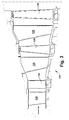
- Figure 2 illustrates a view of an exemplary multi-staged axial compressor 118 that may be used in a gas turbine engine.
- the compressor 118 may include a plurality of stages. Each stage may include a row of compressor rotor blades 120 followed by a row of compressor stator blades 122.
- a first stage may include a row of compressor rotor blades 120, which rotate about a central shaft, followed by a row of compressor stator blades 122, which remain stationary during operation.
- the compressor stator blades 122 generally are circumferentially spaced one from the other and fixed about the axis of rotation.
- the compressor rotor blades 120 are circumferentially spaced and attached to the shaft, when the shaft rotates during operation, the compressor rotor blades 120 rotates about it.
- the compressor rotor blades 120 are configured such that, when spun about the shaft, they impart kinetic energy to the air or working fluid flowing through the compressor 118.
- the compressor 118 may have many other stages beyond the stages that are illustrated in Figure 2 . Additional stages may include a plurality of circumferential spaced compressor rotor blades 120 followed by a plurality of circumferentially spaced compressor stator blades 122.
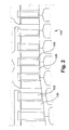
- Figure 3 illustrates a partial view of an exemplary turbine section or turbine 124 that may be used in the gas turbine engine.
- the turbine 124 also may include a plurality of stages. Three exemplary stages are illustrated, but more or less stages may present in the turbine 124.
- a first stage includes a plurality of turbine buckets or turbine rotor blades 126, which rotate about the shaft during operation, and a plurality of nozzles or turbine stator blades 128, which remain stationary during operation.
- the turbine stator blades 128 generally are circumferentially spaced one from the other and fixed about the axis of rotation.
- the turbine rotor blades 126 may be mounted on a turbine wheel (not shown) for rotation about the shaft (not shown).
- a second stage of the turbine 124 also is illustrated.
- the second stage similarly includes a plurality of circumferentially spaced turbine stator blades 128 followed by a plurality of circumferentially spaced turbine rotor blades 126, which are also mounted on a turbine wheel for rotation.
- a third stage is illustrated, and similarly includes a plurality of turbine stator blades 128 and rotor blades 126. It will be appreciated that the turbine stator blades 128 and turbine rotor blades 126 lie in the hot gas path of the turbine 124. The direction of flow of the hot gases through the hot gas path is indicated by the arrow. As one of ordinary skill in the art will appreciate, the turbine 124 may have many other stages beyond the stages that are illustrated in Figure 3 . Each additional stage may include a row of turbine stator blades 128 followed by a row of turbine rotor blades 126.
- rotor blades is a reference to the rotating blades of either the compressor 118 or the turbine 124, which include both compressor rotor blades 120 and turbine rotor blades 126.
- stator blades is a reference to the stationary blades of either the compressor 118 or the turbine 124, which include both compressor stator blades 122 and turbine stator blades 128.
- turbine blades or “blades” will be used herein to refer to either type of blade.
- turbine blades are inclusive to all type of turbine engine blades, including compressor rotor blades 120, compressor stator blades 122, turbine rotor blades 126, and turbine stator blades 128.
- the rotation of compressor rotor blades 120 within the axial compressor 118 may compress a flow of air.
- energy may be released when the compressed air is mixed with a fuel and ignited.
- the resulting flow of hot gases from the combustor 112 then may be directed over the turbine rotor blades 126, which may induce the rotation of the turbine rotor blades 126 about the shaft, thus transforming the energy of the hot flow of gases into the mechanical energy of the rotating blades and, because of the connection between the rotor blades in the shaft, the rotating shaft.
- the mechanical energy of the shaft may then be used to drive the rotation of the compressor rotor blades 120, such that the necessary supply of compressed air is produced, and also, for example, a generator to produce electricity.
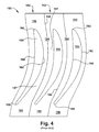
- FIG 4 illustrates a portion of a flow directing assembly 150, according to conventional design, that may be used in a rotary machine, such as in the compressor 106 or the turbine 110 illustrated in Figures 1 through 3 .
- the flow directing assembly 150 has a plurality of blades 152, each having an airfoil 154 and a platform 156.
- the platforms 156 of neighboring blades 152 abut at platform joints 158 with the abutting adjacent platforms 156, forming an inner radial boundary, or "inner wall 157", to the flow passage formed in between neighboring airfoils.
- platforms 156 are configured such that the radial height of neighboring platforms 156 are the same at the platform joint 158 such that a relatively smooth surface is maintained at the joint 158 and along the inner wall.
- each airfoil 154 has a pressure side 160, a suction side 162, a leading edge 163 and a trailing edge 166.
- adjacent airfoils 154 in the assembly 150 form fluid flow passages 164, which include the volume generally bound by the abutting platforms 156 (i.e., the inner wall 157) and, on one side, the pressure side 160 of an airfoil 154, and, on the other side, the suction side 162 of a neighboring airfoil 154.
- the platforms 156 are shaped either in an axisymmetrical way or, as one of ordinary skill in the art will appreciate, in a non-axisymmetrical manner that is aimed at the reducing shock loss that typically occurs across the span of the platform 156.
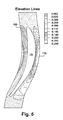
- Figure 5 illustrates a portion of a flow directing assembly 150, in accordance with an exemplary embodiment of the present application that, generally, may be used in, for example, the compressor 106 or the turbine 110 illustrated in Figures 1 through 4 or other types of turbomachinery.
- the platform 156 may include a non-axisymmetric swale or trough 170 generally positioned between neighboring airfoils 154. It has been discovered that troughs configured in accordance with the embodiments described herein offer several operational advantages to the turbine engine.
- forming a trough that, as specified herein, has a desired radial depth, circumferential positioning, contour, and/or axial positioning may decrease the viscous or frictional losses by increasing the volume of the fluid flow passage 164 between airfoils. That is, the increase of volume through the fluid flow passage 164 that the trough 170 provides causes a decrease to the velocity of the working fluid through the fluid flow passage 164, which, as one of ordinary skill in the art will appreciate, reduces frictional losses at the platform 156.
- the troughs 170 of various embodiments of the present invention are generally described in relation to their relative positioning between the airfoils 154 of the two neighboring turbine blades 152.
- the platforms 156 of neighboring turbine blades 152 meet at the joint 158 to form a substantially smooth contour or surface that extends between the pressure side 160 of one turbine blade 152 and the suction side 162 of a neighboring turbine blade 152.
- the platform joint 158 At some point along the surface of the platform 156 between the neighboring airfoils 154 is the platform joint 158 where the two turbine blades 152 abut.
- the troughs 170 are generally formed as continuing contours that extend across the abutting platforms 156 of neighboring blades 152, and, generally, across the joint 158 that marks the nexus of two neighboring blades 152 (though, depending on the configuration of the turbine blades 152 and the joint 150 between them, this is not an absolutely requirement).
- troughs 170 of aspects of the present invention in relation to their positioning on the abutting platforms 156 (which together form the inner wall 157) and, particularly, in relation to their positioning between 156 between the two airfoils 154 that circumferentially bracket them, and not in relation to the platform joint 158 that marks the division between two adjacent blades 152, which, as described, may vary depending on certain other design factors.
- the troughs 170 may comprise a smoothly shaped elongated bowl-like depression formed in the inner wall 157.
- the axis of the elongation of the trough 170 generally runs parallel to the airfoil 154.
- the trough 170 is circumferentially positioned between the airfoils 154 of adjacent turbine blades 152, extending roughly from the area between the leading edges 163 to the area between the trailing edges 166 of the airfoils 154.
- a first side of the trough 170 may be formed at or near the approximate location on the inner wall 157 where the pressure side 160 of an airfoil 154 begins.
- the trough 170 may generally conform to the shape that the pressure side 160 of the airfoil 154 makes at the platform 156 and extend approximately from the leading edge 163 of the pressure side 160 to the trailing edge 166 of the pressure side 160. From this position, the trough 170 may extend circumferentially to a position at or near the suction side 162 of a second airfoil 154 that opposes the first airfoil 154 across the fluid flow passage 164.
- the trough 170 may generally conform to the shape that the suction side 162 of the airfoil 154 makes at the inner wall 157.
- the trough 170 generally resides in the area between the leading edges 163 of neighboring turbine blades 152 and the area between the trailing edges 166 of neighboring turbine blades 152. That is, generally, the trough 170 may be disposed between the axial location of the leading edges 163 and the axial location of the trailing edges 166 within a row of turbine blades 152. Generally, in preferred embodiments, the beginning of the trough 170 is formed in the inner wall 157 at or near the axial location of the leading edges 163 of the turbine blades 152 and extends in a downstream direction to the axial location of the trailing edges 166 of the turbine blades 152.
- the trough 170 In regard to its radial profile or depth, the trough 170 generally slopes radially inward from a shallow depth at its perimeter to a maximum depth near its center.
- the perimeter of the trough 170 may be approximately defined by the pressure side 160 of the airfoil of the first turbine blade 152, a line extending between the leading edges 163 of the first turbine blade 152 and a neighboring second turbine blade 152, the suction side 162 of the second turbine blade 152, and a line extending between the trailing edges 166 of the first and second turbine blades 152.
- the maximum radial depth of the trough 170 may be varied depending on best performance and the size of the overall turbine assembly.
- the maximum radial depth of the trough 170 may be within a range of about 0.0002 and 0.05 m. More preferably, the maximum radial depth may be within a range of about 0.0004 and 0.025 m. And ideally, the maximum radial depth may be within the range of about 0.001 and 0.01 m. Alternatively, in some preferred embodiments, the maximum radial depth may be described in relation to the radial height of the airfoil 154. In such cases, the maximum radial depth of the trough 170 may be within the range of between about 0.1% to 5% of the radial height of the airfoil 154.
- the maximum radial depth of the trough 170 may be within the range of between about 0.25% to 2.5% of the radial height of the airfoil 154. And ideally, the maximum radial depth of the trough 170 may be within the range of between about 0.5% to 1% of the radial height of the airfoil 154.
- Figures 6 and 7 illustrate exemplary embodiments of the contour shape of the trough 170 in accordance with the present invention, with Figure 6 illustrating the axial location of the trough 170 and Figure 7 illustrating the circumferential location of the trough.
- Figure 6 is a side view of a turbine blade 152 that includes an airfoil 154 and a platform 156.
- Figure 6 also includes a section view of the trough 170 (note that the dotted lines illustrate the radial height of a conventional axisymmetrical platform).
- the trough 170 generally extends from about the leading edge 163 to about the trailing edge 166 of the airfoil 154.
- the trough 170 may extend in a downstream direction, through a maximum depth point 175, and terminate at a downstream termination point 176.
- the trough 170 generally forms a smooth convex curve that extends in an inward radial direction.
- the contour shape of the trough 170 may smoothly transition from a convex shape to a concave shape that continues in an inward radial direction.
- the smooth concave curve may continue, though at this point the trough extends in an outward radial direction.
- the contour shape of the trough 170 may smoothly transition from a concave shape to a convex shape that continues in an outward radial direction until it reaches the downstream termination point 176.
- the maximum depth point 175 may be located closer to the upstream termination point 174 than the downstream termination point 176.
- the value will be within the range of 0.1 and 0.9. More preferably, if the axial distance between the upstream termination point 174 and the maximum depth point 175 is divided by the axial distance between the upstream termination point 174 and the downstream termination point 176, the value will be within the range of 0.25 and 0.75.
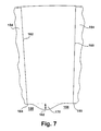
- Figure 7 is a view looking downstream of neighboring turbine blades 152 that each includes an airfoil 154 and a platform 156.
- Figure 7 also includes a section view of the trough 170 (note that the dotted lines illustrate the radial height of a conventional axisymmetrical platform).
- the trough 170 (from right to left in Figure 7 ) generally extends from about the pressure side 160 to about the suction side 162 of neighboring airfoils 154.
- the trough 170 may extend toward the neighboring airfoil 170, through a second maximum depth point 182, and terminate at a suction side termination point 184.
- the trough 170 generally forms a smooth convex curve that extends in an inward radial direction.
- the contour shape of the trough 170 may smoothly transition from a convex shape to a concave shape that continues in an inward radial direction.
- the smooth concave curve may continue, though at this point the trough extends in an outward radial direction.
- the contour shape of the trough 170 may smoothly transition from a concave shape to a convex shape that continues in an outward radial direction until it reaches the suction side termination point 184.
- the second maximum depth point 182 may be located closer to the suction side termination point 184 than the pressure side termination point 180.
- the value will be within the range of 0.1 and 0.6. More preferably, if the circumferential distance between the suction side termination point 184 and the second maximum depth point 182 is divided by the circumferential distance between the suction side termination point 184 and the pressure side termination point 180, the value will be within the range of 0.2 and 0.5.
- a bump or ridge 190 may be formed along the leading edge of the trough 170. It has been discovered that a ridge formed in this location as described herein further decreases the frictional losses between the main flow and the inner wall 157.
- the leading edge ridge 190 may comprise an elongated raised area that resides between the pressure side 160 of the airfoil 154 and the leading edge portions of the trough 170.
- the axis of elongation of the leading edge ridge 190 may form an angle of between approximately 30° and 60° with a line oriented in an axial direction.
- the maximum radial height of the leading edge ridge 190 may be within a range of about 0.00002 and 0.05 m. Alternatively, in some preferred embodiments, the maximum radial height of the leading edge ridge 190 may be described in relation to the radial height of the airfoil 154. In such cases, the maximum radial height of the leading edge ridge 190 may be within the range of between about 0.1% to 5% of the radial height of the airfoil 154.
Landscapes
- Engineering & Computer Science (AREA)
- Physics & Mathematics (AREA)
- Fluid Mechanics (AREA)
- Mechanical Engineering (AREA)
- General Engineering & Computer Science (AREA)
- Structures Of Non-Positive Displacement Pumps (AREA)
- Turbine Rotor Nozzle Sealing (AREA)
Abstract
Description
- This present application relates generally to apparatus, methods and/or systems concerning improved flow-path assemblies in turbine engines. More particularly, but not by way of limitation, the present application relates to apparatus, methods and/or systems pertaining to scalloped areas or troughs formed in turbine blade platforms that deliver enhanced engine performance.
- In rotating turbomachinery, such as the compressor and turbine sections of gas or jet turbine engines and the turbine section of steam turbine engines, flow passages are defined, in part, by radially projecting airfoil surfaces and the surface from which the airfoils extend, which is generally referred to as a platform. During operation, because of the extreme velocity of the main flow, or working fluid, through the turbine, frictional losses occur, particularly as the working fluid flows over the surface area of the platform. It is very desirable to reduce these frictional losses and, thereby, increase the efficiency of the turbine engine.
- The present application thus describes a flow directing assembly for use in a turbine engine comprising: a plurality of circumferentially spaced blades, each of the blades including a radial projecting airfoil with a concave pressure side and a convex suction side that extend from a platform; and a plurality of flow passages, each flow passage defined by the airfoils of neighboring blades and an inner wall formed by abutting platforms of neighboring blades, the inner wall forming the inner radial boundary of the flow passage; wherein the inner wall of one or more of the flow passages comprises means for reducing frictional losses between the flow through the turbine engine and the inner wall. The means for reducing frictional losses may comprise a non-axisymmetrical trough positioned between neighboring airfoils that is configured to reduce frictional losses. Each of the troughs is circumferentially positioned between the airfoils of neighboring blades; and each of the troughs may extend from an area between the leading edges of the airfoils to an area between the trailing edges of the airfoils.
- These and other features of the present application will become apparent upon review of the following detailed description of the preferred embodiments when taken in conjunction with the drawings and the appended claims.
- Various objects and advantages of this invention will be more completely understood and appreciated by careful study of the following more detailed description of exemplary embodiments of the invention taken in conjunction with the accompanying drawings, in which:
-
Figure 1 is a schematic representation of an exemplary turbine engine in which certain embodiments of the present invention may be used; -
Figure 2 is a sectional view of the compressor section of the gas turbine engine ofFigure 1 ; -
Figure 3 is a sectional view of the turbine section of the gas turbine engine ofFigure 1 ; -
Figure 4 is a view from a radially outward position of a portion of a flow directing assembly in which certain embodiments of the present invention may be used; -
Figure 5 is a view from a radially outward position of a portion of a flow directing assembly that has a platform formed with a trough in accordance with an exemplary embodiment of the present invention; -
Figure 6 is a partial sectional view of a platform and airfoil according to an exemplary embodiment of the present invention; and -
Figure 7 is a partial sectional view of a platform and airfoil according to an exemplary embodiment of the present invention. - Referring now to the figures,
Figure 1 illustrates a schematic representation of agas turbine engine 100. In general, gas turbine engines operate by extracting energy from a pressurized flow of hot gas that is produced by the combustion of a fuel in a stream of compressed air. As illustrated inFigure 1 ,gas turbine engine 100 may be configured with anaxial compressor 106 that is mechanically coupled by a common shaft or rotor to a downstream turbine section orturbine 110, and acombustor 112 positioned between thecompressor 106 and theturbine 110. Note that the following invention may be used in all types of turbine engines, including gas turbine engines, steam turbine engines, aircraft engines, and others. Hereinafter, the invention will be described in relation to a gas turbine engine. This description is exemplary only and not intended to be limiting in any way. -
Figure 2 illustrates a view of an exemplary multi-staged axial compressor 118 that may be used in a gas turbine engine. As shown, the compressor 118 may include a plurality of stages. Each stage may include a row ofcompressor rotor blades 120 followed by a row ofcompressor stator blades 122. Thus, a first stage may include a row ofcompressor rotor blades 120, which rotate about a central shaft, followed by a row ofcompressor stator blades 122, which remain stationary during operation. Thecompressor stator blades 122 generally are circumferentially spaced one from the other and fixed about the axis of rotation. Thecompressor rotor blades 120 are circumferentially spaced and attached to the shaft, when the shaft rotates during operation, thecompressor rotor blades 120 rotates about it. As one of ordinary skill in the art will appreciate, thecompressor rotor blades 120 are configured such that, when spun about the shaft, they impart kinetic energy to the air or working fluid flowing through the compressor 118. The compressor 118 may have many other stages beyond the stages that are illustrated inFigure 2 . Additional stages may include a plurality of circumferential spacedcompressor rotor blades 120 followed by a plurality of circumferentially spacedcompressor stator blades 122. -
Figure 3 illustrates a partial view of an exemplary turbine section orturbine 124 that may be used in the gas turbine engine. Theturbine 124 also may include a plurality of stages. Three exemplary stages are illustrated, but more or less stages may present in theturbine 124. A first stage includes a plurality of turbine buckets orturbine rotor blades 126, which rotate about the shaft during operation, and a plurality of nozzles orturbine stator blades 128, which remain stationary during operation. Theturbine stator blades 128 generally are circumferentially spaced one from the other and fixed about the axis of rotation. Theturbine rotor blades 126 may be mounted on a turbine wheel (not shown) for rotation about the shaft (not shown). A second stage of theturbine 124 also is illustrated. The second stage similarly includes a plurality of circumferentially spacedturbine stator blades 128 followed by a plurality of circumferentially spacedturbine rotor blades 126, which are also mounted on a turbine wheel for rotation. A third stage is illustrated, and similarly includes a plurality ofturbine stator blades 128 androtor blades 126. It will be appreciated that theturbine stator blades 128 andturbine rotor blades 126 lie in the hot gas path of theturbine 124. The direction of flow of the hot gases through the hot gas path is indicated by the arrow. As one of ordinary skill in the art will appreciate, theturbine 124 may have many other stages beyond the stages that are illustrated inFigure 3 . Each additional stage may include a row ofturbine stator blades 128 followed by a row ofturbine rotor blades 126. - Note that as used herein, reference, without further specificity, to "rotor blades" is a reference to the rotating blades of either the compressor 118 or the
turbine 124, which include bothcompressor rotor blades 120 andturbine rotor blades 126. Reference, without further specificity, to "stator blades" is a reference to the stationary blades of either the compressor 118 or theturbine 124, which include bothcompressor stator blades 122 andturbine stator blades 128. The term "turbine blades" or "blades" will be used herein to refer to either type of blade. Thus, without further specificity, the term "turbine blades" or "blades" are inclusive to all type of turbine engine blades, includingcompressor rotor blades 120,compressor stator blades 122,turbine rotor blades 126, andturbine stator blades 128. - In use, the rotation of
compressor rotor blades 120 within the axial compressor 118 may compress a flow of air. In thecombustor 112, energy may be released when the compressed air is mixed with a fuel and ignited. The resulting flow of hot gases from thecombustor 112 then may be directed over theturbine rotor blades 126, which may induce the rotation of theturbine rotor blades 126 about the shaft, thus transforming the energy of the hot flow of gases into the mechanical energy of the rotating blades and, because of the connection between the rotor blades in the shaft, the rotating shaft. The mechanical energy of the shaft may then be used to drive the rotation of thecompressor rotor blades 120, such that the necessary supply of compressed air is produced, and also, for example, a generator to produce electricity. -
Figure 4 illustrates a portion of aflow directing assembly 150, according to conventional design, that may be used in a rotary machine, such as in thecompressor 106 or theturbine 110 illustrated inFigures 1 through 3 . Generally, theflow directing assembly 150 has a plurality ofblades 152, each having anairfoil 154 and aplatform 156. Theplatforms 156 of neighboringblades 152 abut atplatform joints 158 with the abuttingadjacent platforms 156, forming an inner radial boundary, or "inner wall 157", to the flow passage formed in between neighboring airfoils. Generally,platforms 156 are configured such that the radial height of neighboringplatforms 156 are the same at theplatform joint 158 such that a relatively smooth surface is maintained at thejoint 158 and along the inner wall. As one of ordinary skill in the art will appreciate, eachairfoil 154 has apressure side 160, asuction side 162, a leadingedge 163 and atrailing edge 166. As illustrated,adjacent airfoils 154 in theassembly 150 formfluid flow passages 164, which include the volume generally bound by the abutting platforms 156 (i.e., the inner wall 157) and, on one side, thepressure side 160 of anairfoil 154, and, on the other side, thesuction side 162 of a neighboringairfoil 154. Typically, theplatforms 156 are shaped either in an axisymmetrical way or, as one of ordinary skill in the art will appreciate, in a non-axisymmetrical manner that is aimed at the reducing shock loss that typically occurs across the span of theplatform 156. -
Figure 5 illustrates a portion of aflow directing assembly 150, in accordance with an exemplary embodiment of the present application that, generally, may be used in, for example, thecompressor 106 or theturbine 110 illustrated inFigures 1 through 4 or other types of turbomachinery. As further illustrated inFigures 6 and7 , in accordance with an exemplary embodiment of the present invention, theplatform 156 may include a non-axisymmetric swale ortrough 170 generally positioned between neighboringairfoils 154. It has been discovered that troughs configured in accordance with the embodiments described herein offer several operational advantages to the turbine engine. As one of ordinary skill in the art will appreciate, during operation, because of the extreme velocity of the working fluid through the turbine, frictional losses occur, particularly as the working fluid flows over the surface area of theplatform 156. However, forming a trough that, as specified herein, has a desired radial depth, circumferential positioning, contour, and/or axial positioning, may decrease the viscous or frictional losses by increasing the volume of thefluid flow passage 164 between airfoils. That is, the increase of volume through thefluid flow passage 164 that thetrough 170 provides causes a decrease to the velocity of the working fluid through thefluid flow passage 164, which, as one of ordinary skill in the art will appreciate, reduces frictional losses at theplatform 156. The reduction of friction losses allows the turbine engine to operate more efficiently. This, of course, is highly desired and an important benefit relating to the troughs designs of the present application. However, as one of ordinary skill in the art will appreciate, other operational benefits may be realized with the troughs designs in accordance with the present application, such as, the reduction of shock loss, improved thermal characteristics, improved cooling characteristics of the turbine blades, and others. - Note that the
troughs 170 of various embodiments of the present invention are generally described in relation to their relative positioning between theairfoils 154 of the two neighboringturbine blades 152. As described, theplatforms 156 of neighboringturbine blades 152 meet at the joint 158 to form a substantially smooth contour or surface that extends between thepressure side 160 of oneturbine blade 152 and thesuction side 162 of a neighboringturbine blade 152. At some point along the surface of theplatform 156 between the neighboringairfoils 154 is the platform joint 158 where the twoturbine blades 152 abut. Thetroughs 170, in accordance with exemplary embodiments of the present application, are generally formed as continuing contours that extend across the abuttingplatforms 156 of neighboringblades 152, and, generally, across the joint 158 that marks the nexus of two neighboring blades 152 (though, depending on the configuration of theturbine blades 152 and the joint 150 between them, this is not an absolutely requirement). Accordingly, it is the intent in this application to describe thetroughs 170 of aspects of the present invention in relation to their positioning on the abutting platforms 156 (which together form the inner wall 157) and, particularly, in relation to their positioning between 156 between the twoairfoils 154 that circumferentially bracket them, and not in relation to the platform joint 158 that marks the division between twoadjacent blades 152, which, as described, may vary depending on certain other design factors. - In general terms, the
troughs 170 may comprise a smoothly shaped elongated bowl-like depression formed in theinner wall 157. The axis of the elongation of thetrough 170 generally runs parallel to theairfoil 154. Further, thetrough 170 is circumferentially positioned between theairfoils 154 ofadjacent turbine blades 152, extending roughly from the area between theleading edges 163 to the area between the trailingedges 166 of theairfoils 154. - More particularly, in relation to the circumferential position of the
troughs 170, a first side of thetrough 170 may be formed at or near the approximate location on theinner wall 157 where thepressure side 160 of anairfoil 154 begins. Thetrough 170 may generally conform to the shape that thepressure side 160 of theairfoil 154 makes at theplatform 156 and extend approximately from theleading edge 163 of thepressure side 160 to the trailingedge 166 of thepressure side 160. From this position, thetrough 170 may extend circumferentially to a position at or near thesuction side 162 of asecond airfoil 154 that opposes thefirst airfoil 154 across thefluid flow passage 164. Thetrough 170 may generally conform to the shape that thesuction side 162 of theairfoil 154 makes at theinner wall 157. - In regard to its axial positioning, the
trough 170 generally resides in the area between theleading edges 163 of neighboringturbine blades 152 and the area between the trailingedges 166 of neighboringturbine blades 152. That is, generally, thetrough 170 may be disposed between the axial location of theleading edges 163 and the axial location of the trailingedges 166 within a row ofturbine blades 152. Generally, in preferred embodiments, the beginning of thetrough 170 is formed in theinner wall 157 at or near the axial location of theleading edges 163 of theturbine blades 152 and extends in a downstream direction to the axial location of the trailingedges 166 of theturbine blades 152. - In regard to its radial profile or depth, the
trough 170 generally slopes radially inward from a shallow depth at its perimeter to a maximum depth near its center. In certain preferred embodiments, as described above, the perimeter of thetrough 170 may be approximately defined by thepressure side 160 of the airfoil of thefirst turbine blade 152, a line extending between theleading edges 163 of thefirst turbine blade 152 and a neighboringsecond turbine blade 152, thesuction side 162 of thesecond turbine blade 152, and a line extending between the trailingedges 166 of the first andsecond turbine blades 152. The maximum radial depth of thetrough 170 may be varied depending on best performance and the size of the overall turbine assembly. In some preferred embodiments, the maximum radial depth of thetrough 170 may be within a range of about 0.0002 and 0.05 m. More preferably, the maximum radial depth may be within a range of about 0.0004 and 0.025 m. And ideally, the maximum radial depth may be within the range of about 0.001 and 0.01 m. Alternatively, in some preferred embodiments, the maximum radial depth may be described in relation to the radial height of theairfoil 154. In such cases, the maximum radial depth of thetrough 170 may be within the range of between about 0.1% to 5% of the radial height of theairfoil 154. More preferably, the maximum radial depth of thetrough 170 may be within the range of between about 0.25% to 2.5% of the radial height of theairfoil 154. And ideally, the maximum radial depth of thetrough 170 may be within the range of between about 0.5% to 1% of the radial height of theairfoil 154. -
Figures 6 and7 illustrate exemplary embodiments of the contour shape of thetrough 170 in accordance with the present invention, withFigure 6 illustrating the axial location of thetrough 170 andFigure 7 illustrating the circumferential location of the trough. It will be appreciated thatFigure 6 is a side view of aturbine blade 152 that includes anairfoil 154 and aplatform 156.Figure 6 also includes a section view of the trough 170 (note that the dotted lines illustrate the radial height of a conventional axisymmetrical platform). As shown, axially, thetrough 170 generally extends from about theleading edge 163 to about the trailingedge 166 of theairfoil 154. That is, at an upstream termination point 174, which may be at about the same axial location as theleading edge 163 of theairfoil 154, thetrough 170 may extend in a downstream direction, through amaximum depth point 175, and terminate at adownstream termination point 176. As illustrated, from the upstream termination point 174 thetrough 170 generally forms a smooth convex curve that extends in an inward radial direction. At a point approximately halfway between the upstream termination point 174 and themaximum depth point 175, the contour shape of thetrough 170 may smoothly transition from a convex shape to a concave shape that continues in an inward radial direction. At themaximum depth point 175, the smooth concave curve may continue, though at this point the trough extends in an outward radial direction. At a point approximately halfway between themaximum depth point 175 and thedownstream termination point 176, the contour shape of thetrough 170 may smoothly transition from a concave shape to a convex shape that continues in an outward radial direction until it reaches thedownstream termination point 176. - As illustrated in
Figure 6 , themaximum depth point 175 may be located closer to the upstream termination point 174 than thedownstream termination point 176. In preferred embodiments, if the axial distance between the upstream termination point 174 and themaximum depth point 175 is divided by the axial distance between the upstream termination point 174 and thedownstream termination point 176, the value will be within the range of 0.1 and 0.9. More preferably, if the axial distance between the upstream termination point 174 and themaximum depth point 175 is divided by the axial distance between the upstream termination point 174 and thedownstream termination point 176, the value will be within the range of 0.25 and 0.75. -
Figure 7 is a view looking downstream of neighboringturbine blades 152 that each includes anairfoil 154 and aplatform 156.Figure 7 also includes a section view of the trough 170 (note that the dotted lines illustrate the radial height of a conventional axisymmetrical platform). As shown, circumferentially, the trough 170 (from right to left inFigure 7 ) generally extends from about thepressure side 160 to about thesuction side 162 of neighboringairfoils 154. That is, at a pressureside termination point 180, which may be at about the circumferential location as thepressure side 160 of theairfoil 154, thetrough 170 may extend toward the neighboringairfoil 170, through a secondmaximum depth point 182, and terminate at a suctionside termination point 184. As illustrated, from the pressureside termination point 180 thetrough 170 generally forms a smooth convex curve that extends in an inward radial direction. At a point approximately halfway between the pressureside termination point 180 and the secondmaximum depth point 182, the contour shape of thetrough 170 may smoothly transition from a convex shape to a concave shape that continues in an inward radial direction. At the secondmaximum depth point 182, the smooth concave curve may continue, though at this point the trough extends in an outward radial direction. At a point approximately halfway between themaximum depth point 175 and the suctionside termination point 184, the contour shape of thetrough 170 may smoothly transition from a concave shape to a convex shape that continues in an outward radial direction until it reaches the suctionside termination point 184. - As illustrated in
Figure 7 , the secondmaximum depth point 182 may be located closer to the suctionside termination point 184 than the pressureside termination point 180. In preferred embodiments, if the circumferential distance between the suctionside termination point 184 and the secondmaximum depth point 182 is divided by the circumferential distance between the suctionside termination point 184 and the pressureside termination point 180, the value will be within the range of 0.1 and 0.6. More preferably, if the circumferential distance between the suctionside termination point 184 and the secondmaximum depth point 182 is divided by the circumferential distance between the suctionside termination point 184 and the pressureside termination point 180, the value will be within the range of 0.2 and 0.5. - In some embodiments, as also illustrated in
Figure 5 , a bump orridge 190 may be formed along the leading edge of thetrough 170. It has been discovered that a ridge formed in this location as described herein further decreases the frictional losses between the main flow and theinner wall 157. Theleading edge ridge 190 may comprise an elongated raised area that resides between thepressure side 160 of theairfoil 154 and the leading edge portions of thetrough 170. In some preferred embodiments, the axis of elongation of theleading edge ridge 190 may form an angle of between approximately 30° and 60° with a line oriented in an axial direction. In some preferred embodiments, the maximum radial height of theleading edge ridge 190 may be within a range of about 0.00002 and 0.05 m. Alternatively, in some preferred embodiments, the maximum radial height of theleading edge ridge 190 may be described in relation to the radial height of theairfoil 154. In such cases, the maximum radial height of theleading edge ridge 190 may be within the range of between about 0.1% to 5% of the radial height of theairfoil 154. - From the above description of preferred embodiments of the invention, those skilled in the art will perceive improvements, changes and modifications. Such improvements, changes and modifications within the skill of the art are intended to be covered by the appended claims. Further, it should be apparent that the foregoing relates only to the described embodiments of the present application and that numerous changes and modifications may be made herein without departing from the spirit and scope of the application as defined by the following claims and the equivalents thereof.
- Various aspects and embodiments of the present invention are defined by the following numbered clauses:
- 1. A flow directing assembly for use in a turbine engine comprising:
- a plurality of circumferentially spaced blades, each of the blades including a radial projecting airfoil with a concave pressure side and a convex suction side that extend from a platform; and
- a plurality of flow passages, each flow passage defined by the airfoils of neighboring blades and an inner wall formed by abutting platforms of neighboring blades, the inner wall forming the inner radial boundary of the flow passage;
- 2. The flow directing assembly according to clause 1, wherein:
- the means for reducing frictional losses comprises a non-axisymmetrical trough positioned between neighboring airfoils that is configured to reduce frictional losses; each of the troughs is circumferentially positioned between the airfoils of neighboring blades; and
- each of the troughs extends from an area between the leading edges of the airfoils to an area between the trailing edges of the airfoils.
- 3. The flow directing assembly according to any preceding clause, wherein:
- each of the troughs comprises a smoothly shaped elongated bowl-like depression formed in the inner wall; and
- the axis of the elongation of each of the troughs extends in an approximate axial direction.
- 4. The flow directing assembly according to any preceding clause, wherein:
- a first side of the trough is formed at or near the location on the inner wall where the pressure side of an first airfoil begins, the first side of the trough generally conforming to the shape that the pressure side of the first airfoil makes at the inner wall;
- a second side of the trough is formed at or near the location on the inner wall where the suction side of a second neighboring airfoil begins, the second side of the trough generally conforming to the shape that the suction side of the second airfoil makes at the inner wall;
- a third side of the trough is formed at or near a line extending between the leading edges of the first turbine blade and the second turbine blade; and
- a fourth side of the trough is formed at or near a line extending between the trailing edges of the first turbine blade and the second turbine blade.
- 5. The flow directing assembly according to any preceding clause, wherein each of the troughs slopes radially inward from a shallow radial depth at the perimeter of the trough to a maximum radial depth at the approximate center of the trough.
- 6. The flow directing assembly according to any preceding clause, wherein each of the troughs is disposed between the axial location of the leading edges and the axial location of the trailing edges of the airfoils within a row of blades.
- 7. The flow directing assembly according to any preceding clause, wherein the maximum radial depth of the trough comprises a value within a range of about 0.0002 to 0.05 m.
- 8. The flow directing assembly according to any preceding clause, wherein the maximum radial depth of the trough comprises a value within a range of about 0.0004 to 0.025 m.
- 9. The flow directing assembly according to any preceding clause, wherein the maximum radial depth of the trough comprises a value within a range of about 0.001 to 0.01 m.
- 10. The flow directing assembly according to any preceding clause, wherein the maximum radial depth of the trough divided by the radial height of the airfoils comprises a value within a range of about 0.001 to 0.05.
- 11. The flow directing assembly according to any preceding clause, wherein the maximum radial depth of the trough divided by the radial height of the airfoils comprises a value within a range of about 0.0025 to 0.025.
- 12. The flow directing assembly according to any preceding clause, wherein the maximum radial depth of the trough divided by the radial height of the airfoils comprises a value within a range of about 0.005 to 0.01.
- 13. The flow directing assembly according to any preceding clause, wherein the trough forms the following described contour in the inner wall as it extends from an upstream termination point, which comprises approximately the same axial location as the leading edge of the airfoils, to a downstream termination point, which comprises approximately the same axial location as the trailing edges of the airfoils:
- from the upstream termination point the trough generally forms a smooth convex curve that extends in an inward radial direction;
- at a point approximately halfway between the upstream termination point and a maximum depth point, the trough smoothly transitions from a convex shape to a concave shape that continues in an inward radial direction;
- at the maximum depth point, the smooth concave curve continues, extending in an outward radial direction; and
- at a point approximately halfway between the maximum depth point and the downstream termination point, the trough smoothly transitions from a concave shape to a convex shape that continues in an outward radial direction until it reaches the downstream termination point.
- 14. The flow directing assembly according to any preceding clause, wherein the maximum depth point is located closer to the upstream termination point than the downstream termination point.
- 15. The flow directing assembly according to any preceding clause, wherein if the axial distance between the upstream termination point and the maximum depth point is divided by the axial distance between the upstream termination point and the downstream termination point, the value is within a range of about 0.1 and 0.9.
- 16. The flow directing assembly according to any preceding clause, wherein if the axial distance between the upstream termination point and the maximum depth point is divided by the axial distance between the upstream termination point and the downstream termination point, the value is within a range of about 0.25 and 0.75.
- 17. The flow directing assembly according to any preceding clause, wherein the trough forms the following described contour in the inner wall as it extends from a pressure side termination point, which comprises approximately the same circumferential location as the pressure side of the airfoils, to a suction side termination point, which comprises approximately the same circumferential location as the suction side of the neighboring airfoils:
- from the pressure side termination point the trough generally forms a smooth convex curve that extends in an inward radial direction;
- at a point approximately halfway between the pressure side termination point and a maximum depth point, the trough smoothly transitions from a convex shape to a concave shape that continues in an inward radial direction;
- at the maximum depth point, the smooth concave curve continues, extending in an outward radial direction; and
- at a point approximately halfway between the maximum depth point and the suction side termination point, the trough smoothly transitions from a concave shape to a convex shape that continues in an outward radial direction until it reaches the suction side termination point.
- 18. The flow directing assembly according to any preceding clause, wherein the maximum depth point is located closer to the suction side termination point than the pressure side termination point.
- 19. The flow directing assembly according to any preceding clause, wherein if the circumferential distance between the suction side termination point and the maximum depth point is divided by the circumferential distance between the suction side termination point and the pressure side termination point, the value is within a range of about 0.1 and 0.6.
- 20. The flow directing assembly according to any preceding clause, wherein if the circumferential distance between the suction side termination point and the maximum depth point is divided by the circumferential distance between the suction side termination point and the pressure side termination point, the value is within a range of about 0.2 and 0.5.
- 21. The flow directing assembly according to any preceding clause, further comprising a leading edge ridge, the leading edge ridge including an elongated raised area that resides approximately between the pressure side of the airfoil and the leading edge portions of the trough.
- 22. The flow directing assembly according to any preceding clause, wherein the axis of elongation of the leading edge ridge forms an angle of between approximately 30° and 60° with a line oriented in an axial direction.
- 23. The flow directing assembly according to any preceding clause, wherein the maximum radial height of the leading edge ridge is within a range of about 0.00002 and 0.05 m.
- 24. The flow directing assembly according to any preceding clause, wherein the maximum radial height of the leading edge ridge divided by the radial height of the airfoils comprises a value within the range of about 0.001 to 0.05.
Claims (10)
- A flow directing assembly (150) for use in a turbine engine (100) comprising:a plurality of circumferentially spaced blades (152), each of the blades (152) including a radial projecting airfoil (154) with a concave pressure side (160) and a convex suction side (162) that extend from a platform (156); anda plurality of flow passages (164), each flow passage (164) defined by the airfoils (154) of neighboring blades (152) and an inner wall (157) formed by abutting platforms (156) of neighboring blades (152), the inner wall (157) forming the inner radial boundary of the flow passage (164);wherein the inner wall (157) of one or more of the flow passages (164) comprises means for reducing frictional losses between the flow through the turbine engine (100) and the inner wall (157).
- The flow directing assembly (150) according to claim 1, wherein:the means for reducing frictional losses comprises a non-axisymmetrical trough (170) positioned between neighboring airfoils (154) that is configured to reduce frictional losses;each of the troughs (170) is circumferentially positioned between the airfoils (154) of neighboring blades (152); andeach of the troughs (170) extends from an area between the leading edges (163) of the airfoils (154) to an area between the trailing edges (166) of the airfoils (154).
- The flow directing assembly (150) according to any preceding claim, wherein:each of the troughs (170) comprises a smoothly shaped elongated bowl-like depression formed in the inner wall (157); andthe axis of the elongation of each of the troughs (170) extends in an approximate axial direction.
- The flow directing assembly (150) according to any preceding claim, wherein:a first side of the trough (170) is formed at or near the location on the inner wall (157) where the pressure side (160) of an first airfoil (154) begins, the first side of the trough (170) generally conforming to the shape that the pressure side (160) of the first airfoil (154) makes at the inner wall (157);a second side of the trough (170) is formed at or near the location on the inner wall (157) where the suction side (162) of a second neighboring airfoil (154) begins, the second side of the trough (170) generally conforming to the shape that the suction side (162) of the second airfoil (154) makes at the inner wall (157);a third side of the trough (170) is formed at or near a line extending between the leading edges (163) of the first turbine blade (152) and the second turbine blade (152); anda fourth side of the trough (170) is formed at or near a line extending between the trailing edges (166) of the first turbine blade (152) and the second turbine blade (152).
- The flow directing assembly (150) according to any preceding claim, wherein each of the troughs (170) is disposed between the axial location of the leading edges (163) and the axial location of the trailing edges (166) of the airfoils (154) within a row of blades (152).
- The flow directing assembly (150) according to any preceding claim, wherein the trough (170) forms the following described contour in the inner wall (157) as it extends from an upstream termination point (174), which comprises approximately the same axial location as the leading edge (163) of the airfoils (154), to a downstream termination point (176), which comprises approximately the same axial location as the trailing edges (166) of the airfoils (154):from the upstream termination point (174) the trough (170) generally forms a smooth convex curve that extends in an inward radial direction;at a point approximately halfway between the upstream termination point (174) and a maximum depth point (175), the trough (170) smoothly transitions from a convex shape to a concave shape that continues in an inward radial direction;at the maximum depth point (175), the smooth concave curve continues, extending in an outward radial direction; andat a point approximately halfway between the maximum depth point (175) and the downstream termination point (176), the trough (170) smoothly transitions from a concave shape to a convex shape that continues in an outward radial direction until it reaches the downstream termination point (176).
- The flow directing assembly (150) according to any preceding claim, wherein the maximum depth point (175) is located closer to the upstream termination point (174) than the downstream termination point (176).
- The flow directing assembly (150) according to any preceding claim, wherein the trough (170) forms the following described contour in the inner wall (157) as it extends from a pressure side termination point (180), which comprises approximately the same circumferential location as the pressure side (160) of the airfoils (154), to a suction side termination point (184), which comprises approximately the same circumferential location as the suction side (162) of the neighboring airfoils (154):from the pressure side termination point (180) the trough (170) generally forms a smooth convex curve that extends in an inward radial direction;at a point approximately halfway between the pressure side termination point (180) and a maximum depth point (175), the trough (170) smoothly transitions from a convex shape to a concave shape that continues in an inward radial direction;at the maximum depth point (175), the smooth concave curve continues, extending in an outward radial direction; andat a point approximately halfway between the maximum depth point (175) and the suction side termination point (184), the trough (170) smoothly transitions from a concave shape to a convex shape that continues in an outward radial direction until it reaches the suction side termination point (184).
- The flow directing assembly (150) according to any preceding claim, wherein the maximum depth point (175) is located closer to the suction side termination point (184) than the pressure side termination point (180).
- The flow directing assembly (150) according to any preceding claim, further comprising a leading edge ridge (190), the leading edge ridge (190) including an elongated raised area that resides approximately between the pressure side (160) of the airfoil (154) and the leading edge portions (163) of the trough (170).
Applications Claiming Priority (1)
| Application Number | Priority Date | Filing Date | Title |
|---|---|---|---|
| US12/347,341 US8231353B2 (en) | 2008-12-31 | 2008-12-31 | Methods and apparatus relating to improved turbine blade platform contours |
Publications (3)
| Publication Number | Publication Date |
|---|---|
| EP2204535A2 true EP2204535A2 (en) | 2010-07-07 |
| EP2204535A3 EP2204535A3 (en) | 2017-12-06 |
| EP2204535B1 EP2204535B1 (en) | 2021-11-10 |
Family
ID=41531571
Family Applications (1)
| Application Number | Title | Priority Date | Filing Date |
|---|---|---|---|
| EP09179197.0A Active EP2204535B1 (en) | 2008-12-31 | 2009-12-15 | Turbine blade platform contours |
Country Status (4)
| Country | Link |
|---|---|
| US (1) | US8231353B2 (en) |
| EP (1) | EP2204535B1 (en) |
| JP (1) | JP2010156335A (en) |
| CN (1) | CN101775999B (en) |
Cited By (7)
| Publication number | Priority date | Publication date | Assignee | Title |
|---|---|---|---|---|
| EP2487329A1 (en) * | 2011-02-08 | 2012-08-15 | MTU Aero Engines GmbH | Blade canal with side wall contours and corresponding fluid flow engine |
| EP2642075A3 (en) * | 2012-03-23 | 2014-03-19 | General Electric Company | Turbine stage and corresponding turbine blade having a scalloped platform |
| WO2014074190A2 (en) | 2012-09-28 | 2014-05-15 | United Technologies Corporation | Endwall contouring |
| WO2015024741A1 (en) * | 2013-08-23 | 2015-02-26 | Siemens Aktiengesellschaft | Blade or vane arrangement for a gas turbine engine |
| US9249666B2 (en) | 2011-12-22 | 2016-02-02 | General Electric Company | Airfoils for wake desensitization and method for fabricating same |
| EP3006161A1 (en) * | 2014-10-09 | 2016-04-13 | Rolls-Royce plc | Abrasive processing method for airfoils |
| EP2589752B1 (en) | 2011-11-01 | 2020-01-01 | United Technologies Corporation | Non Axis-Symmetric Stator Vane Endwall Contour |
Families Citing this family (25)
| Publication number | Priority date | Publication date | Assignee | Title |
|---|---|---|---|---|
| FR2928173B1 (en) | 2008-02-28 | 2015-06-26 | Snecma | DAWN WITH 3D PLATFORM COMPRISING A BULB INTERAUBES. |
| US8727716B2 (en) * | 2010-08-31 | 2014-05-20 | General Electric Company | Turbine nozzle with contoured band |
| US8967973B2 (en) * | 2011-10-26 | 2015-03-03 | General Electric Company | Turbine bucket platform shaping for gas temperature control and related method |
| US9267386B2 (en) | 2012-06-29 | 2016-02-23 | United Technologies Corporation | Fairing assembly |
| EP2885506B8 (en) | 2012-08-17 | 2021-03-31 | Raytheon Technologies Corporation | Contoured flowpath surface |
| CN104520536B (en) * | 2012-09-12 | 2017-03-08 | 三菱日立电力系统株式会社 | Gas turbine |
| WO2014105102A1 (en) | 2012-12-28 | 2014-07-03 | United Technologies Corporation | Platform with curved edges adjacent suction side of airfoil |
| WO2014197062A2 (en) | 2013-03-15 | 2014-12-11 | United Technologies Corporation | Fan exit guide vane platform contouring |
| EP2986823B1 (en) | 2013-04-18 | 2017-11-08 | United Technologies Corporation | Airfoil component |
| EP2818641A1 (en) | 2013-06-26 | 2014-12-31 | Siemens Aktiengesellschaft | Turbine blade with graduated and chamfered platform edge |
| US10378360B2 (en) * | 2013-09-17 | 2019-08-13 | United Technologies Corporation | Fan root endwall contouring |
| US9670781B2 (en) * | 2013-09-17 | 2017-06-06 | Honeywell International Inc. | Gas turbine engines with turbine rotor blades having improved platform edges |
| EP3090126B1 (en) | 2013-11-22 | 2022-05-11 | Raytheon Technologies Corporation | Gas turbine engine component comprising endwall countouring trench |
| CN105298923B (en) * | 2014-06-17 | 2018-01-02 | 中国科学院工程热物理研究所 | Slot type treated casing expands stabilization device after being stitched before compressor |
| EP3158167B1 (en) | 2014-06-18 | 2020-10-07 | Siemens Energy, Inc. | End wall configuration for gas turbine engine |
| US10024163B2 (en) * | 2016-03-01 | 2018-07-17 | General Electric Company | In situ tip repair of an airfoil tip in a gas turbine engine via frictional welding |
| EP3219914A1 (en) * | 2016-03-17 | 2017-09-20 | MTU Aero Engines GmbH | Flow channel, corresponding blade row and turbomachine |
| JP7230058B2 (en) * | 2018-03-30 | 2023-02-28 | シーメンス エナジー グローバル ゲゼルシャフト ミット ベシュレンクテル ハフツング ウント コンパニー コマンディートゲゼルシャフト | Endwall contouring of conical endwalls |
| US11346225B2 (en) | 2018-10-31 | 2022-05-31 | General Electric Company | Airfoil shape for turbine nozzles |
| US10808538B2 (en) | 2018-10-31 | 2020-10-20 | General Electric Company | Airfoil shape for turbine rotor blades |
| US10689993B2 (en) | 2018-11-15 | 2020-06-23 | General Electric Company | Airfoil shape for turbine nozzles |
| US11384640B2 (en) | 2018-11-26 | 2022-07-12 | General Electric Company | Airfoil shape and platform contour for turbine rotor blades |
| CN114687806A (en) * | 2020-12-31 | 2022-07-01 | 中国航发商用航空发动机有限责任公司 | Impeller mechanical blade, molding method thereof and impeller machine |
| DE102021109844A1 (en) | 2021-04-19 | 2022-10-20 | MTU Aero Engines AG | Gas Turbine Blade Assembly |
| US11415010B1 (en) * | 2021-07-05 | 2022-08-16 | Doosan Enerbility Co., Ltd. | Turbine nozzle and gas turbine including the same |
Family Cites Families (11)
| Publication number | Priority date | Publication date | Assignee | Title |
|---|---|---|---|---|
| JP3621523B2 (en) * | 1996-09-25 | 2005-02-16 | 株式会社東芝 | Gas turbine rotor blade cooling system |
| GB9823840D0 (en) * | 1998-10-30 | 1998-12-23 | Rolls Royce Plc | Bladed ducting for turbomachinery |
| US6561761B1 (en) * | 2000-02-18 | 2003-05-13 | General Electric Company | Fluted compressor flowpath |
| US6524070B1 (en) | 2000-08-21 | 2003-02-25 | General Electric Company | Method and apparatus for reducing rotor assembly circumferential rim stress |
| US6478545B2 (en) * | 2001-03-07 | 2002-11-12 | General Electric Company | Fluted blisk |
| US6669445B2 (en) | 2002-03-07 | 2003-12-30 | United Technologies Corporation | Endwall shape for use in turbomachinery |
| JP4640339B2 (en) * | 2004-09-24 | 2011-03-02 | 株式会社Ihi | Wall shape of axial flow machine and gas turbine engine |
| US7465155B2 (en) * | 2006-02-27 | 2008-12-16 | Honeywell International Inc. | Non-axisymmetric end wall contouring for a turbomachine blade row |
| JP4616781B2 (en) * | 2006-03-16 | 2011-01-19 | 三菱重工業株式会社 | Turbine cascade endwall |
| CN101324193B (en) * | 2007-06-15 | 2011-01-19 | 程建平 | Radial double-flow turbine |
| US8206115B2 (en) * | 2008-09-26 | 2012-06-26 | General Electric Company | Scalloped surface turbine stage with trailing edge ridges |
-
2008
- 2008-12-31 US US12/347,341 patent/US8231353B2/en active Active
-
2009
- 2009-12-15 EP EP09179197.0A patent/EP2204535B1/en active Active
- 2009-12-28 JP JP2009296939A patent/JP2010156335A/en active Pending
- 2009-12-31 CN CN200910266748.5A patent/CN101775999B/en active Active
Cited By (12)
| Publication number | Priority date | Publication date | Assignee | Title |
|---|---|---|---|---|
| EP2487329A1 (en) * | 2011-02-08 | 2012-08-15 | MTU Aero Engines GmbH | Blade canal with side wall contours and corresponding fluid flow engine |
| US8985957B2 (en) | 2011-02-08 | 2015-03-24 | Mtu Aero Engines Gmbh | Blade channel having an end wall contour and a turbomachine |
| EP2589752B1 (en) | 2011-11-01 | 2020-01-01 | United Technologies Corporation | Non Axis-Symmetric Stator Vane Endwall Contour |
| US9249666B2 (en) | 2011-12-22 | 2016-02-02 | General Electric Company | Airfoils for wake desensitization and method for fabricating same |
| EP2642075A3 (en) * | 2012-03-23 | 2014-03-19 | General Electric Company | Turbine stage and corresponding turbine blade having a scalloped platform |
| US9085985B2 (en) | 2012-03-23 | 2015-07-21 | General Electric Company | Scalloped surface turbine stage |
| WO2014074190A2 (en) | 2012-09-28 | 2014-05-15 | United Technologies Corporation | Endwall contouring |
| EP2900920A4 (en) * | 2012-09-28 | 2016-07-06 | United Technologies Corp | Endwall contouring |
| WO2015024741A1 (en) * | 2013-08-23 | 2015-02-26 | Siemens Aktiengesellschaft | Blade or vane arrangement for a gas turbine engine |
| US10294796B2 (en) | 2013-08-23 | 2019-05-21 | Siemens Aktiengesellschaft | Blade or vane arrangement for a gas turbine engine |
| EP3006161A1 (en) * | 2014-10-09 | 2016-04-13 | Rolls-Royce plc | Abrasive processing method for airfoils |
| US10287890B2 (en) | 2014-10-09 | 2019-05-14 | Rolls-Royce Plc | Abrasive processing method |
Also Published As
| Publication number | Publication date |
|---|---|
| US20100166558A1 (en) | 2010-07-01 |
| EP2204535A3 (en) | 2017-12-06 |
| CN101775999A (en) | 2010-07-14 |
| EP2204535B1 (en) | 2021-11-10 |
| CN101775999B (en) | 2014-09-24 |
| US8231353B2 (en) | 2012-07-31 |
| JP2010156335A (en) | 2010-07-15 |
Similar Documents
| Publication | Publication Date | Title |
|---|---|---|
| EP2204535B1 (en) | Turbine blade platform contours | |
| EP2241721B1 (en) | Airfoil assembly, corresponding gas turbine engine assembly and method of influencing flow in a gas turbine engine | |
| CN109209511B (en) | Airfoil assembly with scalloped flow surfaces | |
| US10344601B2 (en) | Contoured flowpath surface | |
| US11156099B2 (en) | Turbine engine airfoil with a modified leading edge | |
| EP3138997A1 (en) | Configurations for turbine rotor blade tips | |
| US20170183971A1 (en) | Tip shrouded turbine rotor blades | |
| US20190153873A1 (en) | Engine component with non-diffusing section | |
| US8616838B2 (en) | Systems and apparatus relating to compressor operation in turbine engines | |
| EP3392459A1 (en) | Compressor blades | |
| EP3722556A1 (en) | Turbine section having non-axisymmetric endwall contouring with aft mid-passage peak | |
| CN109891055B (en) | Airfoil for a turbine engine and corresponding method of cooling | |
| EP3329100B1 (en) | Cooling arrangements in tip shrouded turbine rotor blades | |
| EP3722555B1 (en) | Turbine section having non-axisymmetric endwall contouring with forward mid-passage peak | |
| US7534085B2 (en) | Gas turbine engine with contoured air supply slot in turbine rotor | |
| CN106968721B (en) | Internal cooling configuration in turbine rotor blades | |
| WO2019088992A1 (en) | Turbine blade with tip trench | |
| CN111828098A (en) | Turbine engine airfoil having trailing edge | |
| US10900370B2 (en) | Gas turbine engine offtake | |
| WO2018128609A1 (en) | Seal assembly between a hot gas path and a rotor disc cavity | |
| US10508548B2 (en) | Turbine engine with a platform cooling circuit | |
| US11939880B1 (en) | Airfoil assembly with flow surface | |
| US11933193B2 (en) | Turbine engine with an airfoil having a set of dimples |
Legal Events
| Date | Code | Title | Description |
|---|---|---|---|
| PUAI | Public reference made under article 153(3) epc to a published international application that has entered the european phase |
Free format text: ORIGINAL CODE: 0009012 |
|
| AK | Designated contracting states |
Kind code of ref document: A2 Designated state(s): AT BE BG CH CY CZ DE DK EE ES FI FR GB GR HR HU IE IS IT LI LT LU LV MC MK MT NL NO PL PT RO SE SI SK SM TR |
|
| AX | Request for extension of the european patent |
Extension state: AL BA RS |
|
| PUAL | Search report despatched |
Free format text: ORIGINAL CODE: 0009013 |
|
| AK | Designated contracting states |
Kind code of ref document: A3 Designated state(s): AT BE BG CH CY CZ DE DK EE ES FI FR GB GR HR HU IE IS IT LI LT LU LV MC MK MT NL NO PL PT RO SE SI SK SM TR |
|
| AX | Request for extension of the european patent |
Extension state: AL BA RS |
|
| RIC1 | Information provided on ipc code assigned before grant |
Ipc: F01D 5/14 20060101AFI20171031BHEP |
|
| STAA | Information on the status of an ep patent application or granted ep patent |
Free format text: STATUS: REQUEST FOR EXAMINATION WAS MADE |
|
| 17P | Request for examination filed |
Effective date: 20180606 |
|
| RBV | Designated contracting states (corrected) |
Designated state(s): AT BE BG CH CY CZ DE DK EE ES FI FR GB GR HR HU IE IS IT LI LT LU LV MC MK MT NL NO PL PT RO SE SI SK SM TR |
|
| GRAP | Despatch of communication of intention to grant a patent |
Free format text: ORIGINAL CODE: EPIDOSNIGR1 |
|
| STAA | Information on the status of an ep patent application or granted ep patent |
Free format text: STATUS: GRANT OF PATENT IS INTENDED |
|
| INTG | Intention to grant announced |
Effective date: 20210621 |
|
| GRAS | Grant fee paid |
Free format text: ORIGINAL CODE: EPIDOSNIGR3 |
|
| GRAA | (expected) grant |
Free format text: ORIGINAL CODE: 0009210 |
|
| STAA | Information on the status of an ep patent application or granted ep patent |
Free format text: STATUS: THE PATENT HAS BEEN GRANTED |
|
| AK | Designated contracting states |
Kind code of ref document: B1 Designated state(s): AT BE BG CH CY CZ DE DK EE ES FI FR GB GR HR HU IE IS IT LI LT LU LV MC MK MT NL NO PL PT RO SE SI SK SM TR |
|
| REG | Reference to a national code |
Ref country code: GB Ref legal event code: FG4D |
|
| REG | Reference to a national code |
Ref country code: AT Ref legal event code: REF Ref document number: 1446287 Country of ref document: AT Kind code of ref document: T Effective date: 20211115 Ref country code: CH Ref legal event code: EP |
|
| REG | Reference to a national code |
Ref country code: DE Ref legal event code: R096 Ref document number: 602009064144 Country of ref document: DE |
|
| REG | Reference to a national code |
Ref country code: IE Ref legal event code: FG4D |
|
| REG | Reference to a national code |
Ref country code: LT Ref legal event code: MG9D |
|
| REG | Reference to a national code |
Ref country code: NL Ref legal event code: MP Effective date: 20211110 |
|
| REG | Reference to a national code |
Ref country code: AT Ref legal event code: MK05 Ref document number: 1446287 Country of ref document: AT Kind code of ref document: T Effective date: 20211110 |
|
| PG25 | Lapsed in a contracting state [announced via postgrant information from national office to epo] |
Ref country code: LT Free format text: LAPSE BECAUSE OF FAILURE TO SUBMIT A TRANSLATION OF THE DESCRIPTION OR TO PAY THE FEE WITHIN THE PRESCRIBED TIME-LIMIT Effective date: 20211110 Ref country code: FI Free format text: LAPSE BECAUSE OF FAILURE TO SUBMIT A TRANSLATION OF THE DESCRIPTION OR TO PAY THE FEE WITHIN THE PRESCRIBED TIME-LIMIT Effective date: 20211110 Ref country code: BG Free format text: LAPSE BECAUSE OF FAILURE TO SUBMIT A TRANSLATION OF THE DESCRIPTION OR TO PAY THE FEE WITHIN THE PRESCRIBED TIME-LIMIT Effective date: 20220210 Ref country code: AT Free format text: LAPSE BECAUSE OF FAILURE TO SUBMIT A TRANSLATION OF THE DESCRIPTION OR TO PAY THE FEE WITHIN THE PRESCRIBED TIME-LIMIT Effective date: 20211110 |
|
| PG25 | Lapsed in a contracting state [announced via postgrant information from national office to epo] |
Ref country code: IS Free format text: LAPSE BECAUSE OF FAILURE TO SUBMIT A TRANSLATION OF THE DESCRIPTION OR TO PAY THE FEE WITHIN THE PRESCRIBED TIME-LIMIT Effective date: 20220310 Ref country code: SE Free format text: LAPSE BECAUSE OF FAILURE TO SUBMIT A TRANSLATION OF THE DESCRIPTION OR TO PAY THE FEE WITHIN THE PRESCRIBED TIME-LIMIT Effective date: 20211110 Ref country code: PT Free format text: LAPSE BECAUSE OF FAILURE TO SUBMIT A TRANSLATION OF THE DESCRIPTION OR TO PAY THE FEE WITHIN THE PRESCRIBED TIME-LIMIT Effective date: 20220310 Ref country code: PL Free format text: LAPSE BECAUSE OF FAILURE TO SUBMIT A TRANSLATION OF THE DESCRIPTION OR TO PAY THE FEE WITHIN THE PRESCRIBED TIME-LIMIT Effective date: 20211110 Ref country code: NO Free format text: LAPSE BECAUSE OF FAILURE TO SUBMIT A TRANSLATION OF THE DESCRIPTION OR TO PAY THE FEE WITHIN THE PRESCRIBED TIME-LIMIT Effective date: 20220210 Ref country code: NL Free format text: LAPSE BECAUSE OF FAILURE TO SUBMIT A TRANSLATION OF THE DESCRIPTION OR TO PAY THE FEE WITHIN THE PRESCRIBED TIME-LIMIT Effective date: 20211110 Ref country code: LV Free format text: LAPSE BECAUSE OF FAILURE TO SUBMIT A TRANSLATION OF THE DESCRIPTION OR TO PAY THE FEE WITHIN THE PRESCRIBED TIME-LIMIT Effective date: 20211110 Ref country code: HR Free format text: LAPSE BECAUSE OF FAILURE TO SUBMIT A TRANSLATION OF THE DESCRIPTION OR TO PAY THE FEE WITHIN THE PRESCRIBED TIME-LIMIT Effective date: 20211110 Ref country code: GR Free format text: LAPSE BECAUSE OF FAILURE TO SUBMIT A TRANSLATION OF THE DESCRIPTION OR TO PAY THE FEE WITHIN THE PRESCRIBED TIME-LIMIT Effective date: 20220211 Ref country code: ES Free format text: LAPSE BECAUSE OF FAILURE TO SUBMIT A TRANSLATION OF THE DESCRIPTION OR TO PAY THE FEE WITHIN THE PRESCRIBED TIME-LIMIT Effective date: 20211110 |
|
| PG25 | Lapsed in a contracting state [announced via postgrant information from national office to epo] |
Ref country code: SM Free format text: LAPSE BECAUSE OF FAILURE TO SUBMIT A TRANSLATION OF THE DESCRIPTION OR TO PAY THE FEE WITHIN THE PRESCRIBED TIME-LIMIT Effective date: 20211110 Ref country code: SK Free format text: LAPSE BECAUSE OF FAILURE TO SUBMIT A TRANSLATION OF THE DESCRIPTION OR TO PAY THE FEE WITHIN THE PRESCRIBED TIME-LIMIT Effective date: 20211110 Ref country code: RO Free format text: LAPSE BECAUSE OF FAILURE TO SUBMIT A TRANSLATION OF THE DESCRIPTION OR TO PAY THE FEE WITHIN THE PRESCRIBED TIME-LIMIT Effective date: 20211110 Ref country code: EE Free format text: LAPSE BECAUSE OF FAILURE TO SUBMIT A TRANSLATION OF THE DESCRIPTION OR TO PAY THE FEE WITHIN THE PRESCRIBED TIME-LIMIT Effective date: 20211110 Ref country code: DK Free format text: LAPSE BECAUSE OF FAILURE TO SUBMIT A TRANSLATION OF THE DESCRIPTION OR TO PAY THE FEE WITHIN THE PRESCRIBED TIME-LIMIT Effective date: 20211110 Ref country code: CZ Free format text: LAPSE BECAUSE OF FAILURE TO SUBMIT A TRANSLATION OF THE DESCRIPTION OR TO PAY THE FEE WITHIN THE PRESCRIBED TIME-LIMIT Effective date: 20211110 |
|
| REG | Reference to a national code |
Ref country code: CH Ref legal event code: PL |
|
| REG | Reference to a national code |
Ref country code: DE Ref legal event code: R097 Ref document number: 602009064144 Country of ref document: DE |
|
| PG25 | Lapsed in a contracting state [announced via postgrant information from national office to epo] |
Ref country code: MC Free format text: LAPSE BECAUSE OF FAILURE TO SUBMIT A TRANSLATION OF THE DESCRIPTION OR TO PAY THE FEE WITHIN THE PRESCRIBED TIME-LIMIT Effective date: 20211110 |
|
| PLBE | No opposition filed within time limit |
Free format text: ORIGINAL CODE: 0009261 |
|
| STAA | Information on the status of an ep patent application or granted ep patent |
Free format text: STATUS: NO OPPOSITION FILED WITHIN TIME LIMIT |
|
| REG | Reference to a national code |
Ref country code: BE Ref legal event code: MM Effective date: 20211231 |
|
| 26N | No opposition filed |
Effective date: 20220811 |
|
| GBPC | Gb: european patent ceased through non-payment of renewal fee |
Effective date: 20220210 |
|
| PG25 | Lapsed in a contracting state [announced via postgrant information from national office to epo] |
Ref country code: LU Free format text: LAPSE BECAUSE OF NON-PAYMENT OF DUE FEES Effective date: 20211215 Ref country code: IE Free format text: LAPSE BECAUSE OF NON-PAYMENT OF DUE FEES Effective date: 20211215 |
|
| PG25 | Lapsed in a contracting state [announced via postgrant information from national office to epo] |
Ref country code: SI Free format text: LAPSE BECAUSE OF FAILURE TO SUBMIT A TRANSLATION OF THE DESCRIPTION OR TO PAY THE FEE WITHIN THE PRESCRIBED TIME-LIMIT Effective date: 20211110 Ref country code: FR Free format text: LAPSE BECAUSE OF NON-PAYMENT OF DUE FEES Effective date: 20220110 Ref country code: BE Free format text: LAPSE BECAUSE OF NON-PAYMENT OF DUE FEES Effective date: 20211231 |
|
| PG25 | Lapsed in a contracting state [announced via postgrant information from national office to epo] |
Ref country code: LI Free format text: LAPSE BECAUSE OF NON-PAYMENT OF DUE FEES Effective date: 20211231 Ref country code: CH Free format text: LAPSE BECAUSE OF NON-PAYMENT OF DUE FEES Effective date: 20211231 |
|
| PG25 | Lapsed in a contracting state [announced via postgrant information from national office to epo] |
Ref country code: GB Free format text: LAPSE BECAUSE OF NON-PAYMENT OF DUE FEES Effective date: 20220210 |
|
| PGFP | Annual fee paid to national office [announced via postgrant information from national office to epo] |
Ref country code: IT Payment date: 20221122 Year of fee payment: 14 |
|
| PG25 | Lapsed in a contracting state [announced via postgrant information from national office to epo] |
Ref country code: HU Free format text: LAPSE BECAUSE OF FAILURE TO SUBMIT A TRANSLATION OF THE DESCRIPTION OR TO PAY THE FEE WITHIN THE PRESCRIBED TIME-LIMIT; INVALID AB INITIO Effective date: 20091215 Ref country code: CY Free format text: LAPSE BECAUSE OF FAILURE TO SUBMIT A TRANSLATION OF THE DESCRIPTION OR TO PAY THE FEE WITHIN THE PRESCRIBED TIME-LIMIT Effective date: 20211110 |
|
| P01 | Opt-out of the competence of the unified patent court (upc) registered |
Effective date: 20230522 |
|
| REG | Reference to a national code |
Ref country code: DE Ref legal event code: R082 Ref document number: 602009064144 Country of ref document: DE Ref country code: DE Ref legal event code: R081 Ref document number: 602009064144 Country of ref document: DE Owner name: GENERAL ELECTRIC TECHNOLOGY GMBH, CH Free format text: FORMER OWNER: GENERAL ELECTRIC COMPANY, SCHENECTADY, NY, US |
|
| PGFP | Annual fee paid to national office [announced via postgrant information from national office to epo] |
Ref country code: DE Payment date: 20231121 Year of fee payment: 15 |