EP1947228A2 - Apparatus for driving embroidery frame of embroidery machine - Google Patents
Apparatus for driving embroidery frame of embroidery machine Download PDFInfo
- Publication number
- EP1947228A2 EP1947228A2 EP07011161A EP07011161A EP1947228A2 EP 1947228 A2 EP1947228 A2 EP 1947228A2 EP 07011161 A EP07011161 A EP 07011161A EP 07011161 A EP07011161 A EP 07011161A EP 1947228 A2 EP1947228 A2 EP 1947228A2
- Authority
- EP
- European Patent Office
- Prior art keywords
- frame
- embroidery frame
- embroidery
- sewing machine
- driving unit
- Prior art date
- Legal status (The legal status is an assumption and is not a legal conclusion. Google has not performed a legal analysis and makes no representation as to the accuracy of the status listed.)
- Withdrawn
Links
Images


Classifications
-
- D—TEXTILES; PAPER
- D05—SEWING; EMBROIDERING; TUFTING
- D05C—EMBROIDERING; TUFTING
- D05C9/00—Appliances for holding or feeding the base fabric in embroidering machines
- D05C9/02—Appliances for holding or feeding the base fabric in embroidering machines in machines with vertical needles
- D05C9/04—Work holders, e.g. frames
- D05C9/06—Feeding arrangements therefor, e.g. influenced by patterns, operated by pantographs
-
- D—TEXTILES; PAPER
- D05—SEWING; EMBROIDERING; TUFTING
- D05B—SEWING
- D05B21/00—Sewing machines with devices for automatically controlling movement of work-carrier relative to stitch-forming mechanism in order to obtain particular configuration of seam, e.g. programme-controlled for sewing collars, for attaching pockets
Definitions
- the present invention relates to an apparatus for driving an embroidery frame of a sewing machine, and more particularly, to a driving apparatus of an embroidery frame of a sewing machine in which a driving unit of a sewing frame (embroidery frame) reciprocates on an X-axis fixed frame and/or a Y-axis fixed frame which is installed to a beam-body of the sewing machine so that an uniform driving force can be transmitted to overall the embroidery frame, inferior embroidery caused by vibration of the embroidery frame during the transfer can be prevented, a size of a table of the sewing machine is reduced, and a high-speed operation is enabled.
- a driving unit of a sewing frame embroidery frame
- the embroidery machine represents a machine in which a sewing needle bar moves up and down and an embroidery frame, to which a workpiece fabric is fixed, travels in the X-axis direction and the Y-axis direction to embroider as a user wishes.
- the sewing machine is usually used in home.
- the embroidery frame to hold the workpiece fabric moves in the X-axis direction and the Y-axis direction to embroider the workpiece fabric, the precise movement and a constant speed of the embroidery frame are closely connected to the quality of the embroidery.
- a servo motor or an induction motor capable of controlling speed is used as a driving unit to move the needle bar of the embroidery machine up and down
- a stepping motor which has an excellent positioning function and is easy to control is usually used as a driving unit to move the embroidery machine in the X-axis direction and the Y-axis direction.
- the embroidery machine there are several types of the embroidery machine such as a single head type automatic embroidery machine having a single head, a multi-head type automatic embroidery machine having two or more heads, and a special embroidery machine such as a computer quilting machine.
- FIG. 1 is an external appearance of a conventional multi-head type automatic embroidery machine
- FIG. 2 is a view illustrating a head and a shuttle driving unit of the embroidery machine in FIG. 1 .
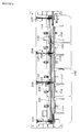
- the multi-head type automatic embroidery machine includes a beam-body 1 to support the embroidery machine, a table 2 installed on the beam-body 1, an embroidery frame (or an embroidery table) 3 installed on the table 2 to fix cloth to be embroidered, a plurality of heads 4 installed on an upper shaft 11 upper than the embroidery frame 3 to perform the embroidery, a shuttle (or a hook) 15 installed on a lower shaft 12 lower than the table 2 to face the heads 4 and to feed a lower thread, a main controller box 5 installed at the lower side of the table 2, and a manipulation panel 6 installed at a side of the table 2.
- a main shaft driving motor 13 is installed at a lower side of the table 2.
- a first belt 14a connects a rotation shaft of the main shaft driving motor 13 and the lower shaft 12, and the lower shaft 12 and the upper shaft 11 is connected to each other by a second belt 14b.
- the lower shaft 12 and the upper shaft 11 rotate. Due to the rotation of the lower shaft 12, the shuttle 15 is driven to feed the lower thread for the embroidery. Due to the rotation of the upper shaft 11, the needle bar 4a installed in the head 4 is driven to embroider the cloth.
- the embroidery machine usually includes a plurality of head 4 (for example, 10 to 24 heads).
- the plural heads 4 are connected to each other by a signal rotation shaft (upper shaft), each of the heads 4 has a plurality of needles (for example, 6 to 15 needles), and different colored various threads are connected to the respective needles.
- the heads 4 embroider the cloth using various colored threads according to a desired embroidery pattern.
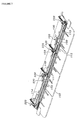
- FIG. 3 is a plan view illustrating a driving apparatus of an embroidery frame of the conventional automatic embroidery machine having two embroidery heads.
- the conventional driving apparatus of an embroidery frame of a sewing machine includes a table 6 to which an object to be embroidered is placed, an embroidery frame 26 installed at the upper side of the table 6 to fix the object to be embroidered, and an elongated frame driving unit 10 to hold the embroidery frame 26.
- the embroidery frame 26 includes a pair of elongated horizontal frames and a pair of a vertical frames, installed at the upper side of the table 6, to support the object to be embroidered, and has a rectangular shape.
- a movement mechanism 59 is installed to move the embroidery frame 26 on the sewing table 6 in the front-to-rear direction (Y-direction) and in the right-to-left direction (X-direction).
- a Y-directional movement mechanism 11 is installed to move the embroidery frame 26 in the Y-direction.
- the Y-directional movement mechanism 11 includes pulleys 67 and 68 supported to rotate at the front side and the rear side thereof, two elongated belts 69 and 70 extended between the pulleys 67 and 68, and a Y-directional driving motor 14 connected to the right and left pulleys 68, positioned at the rear side, by a connecting shaft 13.
- the two right and left belts 68 and 70 and the frame driving unit 10 are connected to each other by slits 12 formed in the Y-direction of the sewing table 6.
- the forward and backward rotation of the Y-directional driving motor 14 is controller such that the frame driving unit 10 and the embroidery frame 26 held by the frame driving unit 10 are moved in the Y-direction.
- cylindrical supports 7 are installed to correspond to the heads 5.
- an X-directional movement mechanism 21 is installed to move the embroidery frame 26 in the X-direction.
- the X-directional movement mechanism 21 includes pulleys 71 and 72 rotatably supported by the right and left ends thereof, an elongated belt 73 extended between the pulleys 71 and 72, and an X-directional driving motor directly connected to the right pulley 72.
- Connecting bodies 75 are connected to the belt 73 by a predetermined distance, the embroidery frame 26 is horizontally attached to the connecting bodies 75 to protrude toward the front side of the frame driving unit 10.
- the X-directional driving motor 74 rotates forward and backward so that the embroidery frame 26 reciprocates in the X-direction.
- the length of the timing belt is also increased in the Y-direction. If the length of the timing belt is elongated in the Y-direction, vibration may be easily generated as much as the increased length, there is generated a backlash so that it is difficult to transmit the driving force and there is a limit for a high-speed operation.
- the overall width of the sewing machine is increased.
- the present invention has been made to solve the above-mentioned problems occurring in the prior art, and it is an aspect of the present invention to provide a driving apparatus of an embroidery frame of a sewing machine in which an embroidery frame driving unit reciprocates on an X-axis fixed frame and/or a Y-axis fixed frame which is installed in a beam-body of the sewing machine so that a uniform movement driving force can be transmitted to overall the embroidery frame, the embroidery can be precisely performed according to embroidery data at a high-speed to obtain high-quality embroidered patterns, and the Y-directional width of the sewing machine is decreased to reduce overall width of the sewing machine.
- a driving apparatus of an embroidery frame of a sewing machine including: at least one X-directional movement mechanism to move the embroidery frame to support an object to be embroidered in right-to-left direction (X-direction); and at least one Y-directional movement mechanism to move the embroidery frame to support an object to be embroidered in front-to-rear direction (Y-direction); any one of the X-directional movement mechanism and the Y-directional movement mechanism including: a fixed frame installed to a beam-body of the sewing machine and having gear teeth; and an embroidery frame driving unit installed on the fixed frame to reciprocate and engaged with the gear teeth to reciprocate the embroidery frame.
- a driving apparatus of an embroidery frame of a sewing machine including: an embroidery frame driving unit having the embroidery frame to fix and hold an object to be embroidered and placed on a table of the sewing machine; and at least one Y-directional movement mechanism to move the frame driving unit in the front-to-rear direction; the Y-directional movement mechanism including: a fixed frame installed in the upper side of the frame driving unit in the Y-direction and having gear teeth; and an embroidery frame driving unit installed on the fixed frame to reciprocate and engaged with the gear teeth to reciprocate the frame driving unit in the Y-direction.
- the driving apparatus further includes an X-directional movement mechanism installed in the frame driving unit to reciprocate the embroidery frame in the X-direction, wherein the X-directional movement mechanism includes: a movable frame installed on the frame driving unit to reciprocate in the X-direction (right-to-left direction) and having gear teeth; and an embroidery frame driving unit engaged with the gear teeth of the movable frame to reciprocate the movable frame in the X-direction.
- the movable frame includes a connecting body to freely detach the embroidery frame.
- the embroidery frame driving unit includes: an engaging member engaged with the gear teeth formed in the fixed frame; a plurality of rotation members to rotatably support the engaging member; and a driving body to provide a rotational force to the engaging member.
- the engaging member includes a belt-type member.
- the belt-type member includes gear teeth engaged with the gear teeth formed in the fixed frame.
- the driving body includes gear teeth engaged with the engaging member.
- the embroidery frame driving unit includes: an engaging member engaged with the gear teeth formed in the upper side of the fixed frame; and a driving body to provide a rotational force to the engaging member.
- the engaging member includes a pinion.
- Power sources are individually installed in the embroidery frame driving units.
- the embroidery frame driving unit is driven by a single power source.
- the beam-body includes a table.
- the embroidery frame driving unit is installed in the beam-body of the sewing machine to reciprocate on the X-axis fixed frame and/or the Y-axis fixed frame so that a uniform movement driving force can be transmitted to overall embroidery frame, the deterioration of the quality of the embroidery product due to the vibration of the embroidery frame during the movement can be prevented, and the size of the table of the sewing machine can be reduced.
- FIGS. 4 and 5 are front and rear perspective views illustrating a sewing machine having a driving apparatus of an embroidery frame of a sewing machine according to an embodiment of the present invention
- FIGS. 6 and 7 are a plan view and a perspective view illustrating the driving apparatus of an embroidery frame of a sewing machine according to the embodiment of the present invention
- FIG. 8 is a side view illustrating the driving apparatus of an embroidery frame of a sewing machine according to the present invention
- FIGS. 9 and 10 are detailed views illustrating an embroidery frame driving unit of a sewing machine according to the embodiment of the present invention
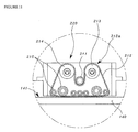
- FIG. 11 is a view illustrating an example of a movement mechanism employed in the present invention such as a Y-directional movement mechanism.
- the driving apparatus of an embroidery frame includes at least one X-directional movement mechanism 120 to move an embroidery frame 111 to support an object to be embroidered in the right-to-left direction (X-direction), and at least one Y-direction movement mechanism 220 to move the embroidery frame 111 in the front-to-rear direction (Y-direction).
- one of the X-directional movement mechanism 120 and the Y-directional movement mechanism 220 includes a fixed frame 140 installed to a beam-body of the sewing machine and having gear teeth, and embroidery frame driving units 150 installed on the fixed frame 140 to reciprocate and engaged with the gear teeth to reciprocate the embroidery frame 111.
- the driving apparatus of an embroidery frame of a sewing machine 100 includes a frame driving unit 108 having the embroidery frame 111 to fix and hold the object to be embroidered and placed on a table 102 of the sewing machine 100, and at least one Y-directional movement mechanism 220 to move the frame driving unit 108 in the forward and backward direction of the sewing machine 100.
- the Y-directional movement mechanism 220 includes a fixed frame 140 installed in the upper side of the frame driving unit 108 in the Y-direction and having gear teeth, and an embroidery frame driving unit 150 installed on the fixed frame 140 to reciprocate and engaged with the gear teeth to reciprocate the frame driving unit 108 forward and backward in the Y-direction.
- the driving apparatus of an embroidery frame of a sewing machine further includes an X-directional movement mechanism 120 installed in the frame driving unit 108 to reciprocate the embroidery frame 11 in the X-direction.
- the X-directional movement mechanism 120 includes a movable frame 112 installed on the frame driving unit 108 in the X-direction (right-to-left direction) and having gear teeth, and an embroidery frame driving unit 150 engaged with the gear teeth of the movable frame 112 to reciprocate the movable frame 112 in the X-direction.
- the embroidery frame driving unit 150 includes an engaging member 212 engaged with the gear teeth formed in the fixed frame 140, a plurality of rotation members 213 to 215 to rotatably support the engaging member 212, and a driving body 211 to provide a rotational force to the engaging member 212.
- the engaging member 212 is implemented by a belt-type member having gear teeth 212a engaged with the gear teeth 141 formed in the fixed frame 140.
- the plurality of rotation members 213 to 215 supports the engaging member 212
- the driving body 211 is positioned between rotation members among the plural rotation members 213 to 215 installed at the positions higher than rotation shafts of the rotation members positioned at the lower side and at the lower side
- the engaging member 212 has a reversed U-shape formed by the driving body 211 installed between the two rotation members.
- the plurality of rotation members 213 to 215 is implemented by idlers.
- the embroidery frame driving unit 150 of the Y-directional movement mechanism 220 has been described, the embroidery frame driving unit 150 of the X-directional movement mechanism 120 can be implemented as the configuration of the embroidery frame driving unit 150 of the Y-directional movement mechanism 220.
- the embroidery frame 111 to fix and hold the object to be embroidered can be freely attached to and detached from the movable frame 112 by the connecting body 113.
- a Y-axis driving motor 230 to driving the embroidery frame driving unit 150 is preferably provided in the embroidery frame driving unit 150 of the Y-directional movement mechanism 220 positioned at the center, among a plurality of Y-directional movement mechanisms 220 so as to provide a uniform driving force.
- a pulley (not shown), mounted to a connecting shaft 114 elongated in the X-direction to drive driving bodies 211 of the respective embroidery frame driving units, is connected to a driving shaft (not shown) of the Y-axis driving motor 230 by a timing belt (not shown) to drive and move the respective embroidery frame driving units.
- one sides (front ends) thereof are fixed to upper frames 104 by first brackets 116 and the opposite sides (rear ends) thereof are fixed to a lower frame 110 by second brackets 117 (See FIG. 8 ).
- the Y-directional movement mechanism 220 is fixed as such a front end is fixed to a supporting shaft to support the upper frame 104 and a rear end is fixed to a rear side of the lower frame 110.
- a fixing member 118 to fix the frame driving unit 108 is provided such that the fixing member 118 reciprocates together the embroidery frame driving unit 150 with respect to the fixed frame 140 to move the frame driving unit 108 in the front-to-rear direction (Y-direction) of the sewing machine.
- the fixed frame 140 of the Y-directional movement mechanism 220 may be installed in the lower side of the table 102, and the embroidery frame driving unit 150 may reciprocate on the table 102 in the front-to-rear direction (Y-direction) due to a slit formed in the table 102 in the Y-direction.
- the X-directional movement mechanism 120 is installed in the frame driving unit 108 such that the embroidery frame driving unit 150 moves the movable frame 112 in the right-to-left direction (X-direction) to move the embroidery frame 111
- the fixed frame 140 is installed in the frame driving unit 108 and the embroidery frame driving unit 150 reciprocates thereon to move the embroidery frame 11 in the right-to-left direction (X-direction).
- power sources to provide the driving force to the movement mechanisms of the embroidery frame described in the embodiments of the present invention may be individually installed to the embroidery frame driving units, or a power source may use a single common driving motor such that a single output shaft is connected to plural driving boxes to drive the movable frame.
- the engaging member installed in the embroidery frame driving unit may be a belt type power transmitting member such as a timing belt, a chain, or a driven gear directly engaged with the driving body.
- the driving body installed in the embroidery frame driving unit and connected to the power source includes all of devices and units to transmit the driving force of the power source such as a timing pulley, a sprocket, a driving gear, a driving pulley, and the like.
- the above-described driving apparatus of an embroidery frame of a sewing machine can be applied to every sewing machine to which the Y-directional movement mechanism or the X-directional movement mechanism is applied.
- the embroidery frame driving unit 150 may include an engaging member engaged with the gear teeth formed in the upper side of the fixed frame, and a driving body to provide the rotational force to the engaging member.
- a pinion may be used as the engaging member.
- the embroidery frame driving unit is installed in the beam-body of the sewing machine to reciprocate on the X-axis fixed frame and/or the Y-axis fixed frame so that a uniform movement driving force can be transmitted to overall embroidery frame, the embroidery is precisely performed according to embroidery data at a high-speed to obtain a high-quality embroidery product, and the Y-direction width of the sewing machine is reduced to decrease the overall width of the sewing machine.
- the movement mechanisms to drive the embroidery frame are installed in the upper side of the table of the sewing machine to transmit a uniform movement driving force to the embroidery frame driving unit, and the deflection and deformation of the embroidery frame driving unit are prevented to precisely drive the embroidery frame at a high-speed to obtain high-quality embroidery patterns.
- the embroidery frame driving unit of a sewing machine having a rack and pinion type power transmission to precisely transmit a driving force using a timing belt with gear teeth, engaged with the gear teeth of the fixed frame having the gear teeth and installed in the beam-body of the sewing machine, is provided, so that a uniform movement driving force can be transmitted to the overall embroidery frame, the embroidery is precisely performed according to the embroidery data at a high-speed to obtain high-quality embroidery patterns, and the Y-directional width of the sewing machine is reduced to decrease the overall width of the sewing machine.
- the precision, the high-speed operation, and the durability of the embroidery frame can be achieved, as well, it is possible to minimize the increase of the number of components, costs, and driving noise, to prevent the deflection of the embroidery frame, and to achieve the precise operation of the embroidery frame even when driving a large sized embroidery frame.
Abstract
Description
- The present invention relates to an apparatus for driving an embroidery frame of a sewing machine, and more particularly, to a driving apparatus of an embroidery frame of a sewing machine in which a driving unit of a sewing frame (embroidery frame) reciprocates on an X-axis fixed frame and/or a Y-axis fixed frame which is installed to a beam-body of the sewing machine so that an uniform driving force can be transmitted to overall the embroidery frame, inferior embroidery caused by vibration of the embroidery frame during the transfer can be prevented, a size of a table of the sewing machine is reduced, and a high-speed operation is enabled.
- As generally known in the art, there are an embroidery machine and a sewing machine as sewing machines. The embroidery machine represents a machine in which a sewing needle bar moves up and down and an embroidery frame, to which a workpiece fabric is fixed, travels in the X-axis direction and the Y-axis direction to embroider as a user wishes. The sewing machine is usually used in home.
- There is a difference between the sewing machine and the embroidery machine in view that the sewing machine moves the workpiece fabric by a saw tooth-shaped mover and sews the workpiece fabric and the embroidery machine transfers the embroidery frame to hold the workpiece fabric in the X-axis direction and the Y-axis direction to embroider the workpiece fabric.
- In the embroidery machine, since the embroidery frame to hold the workpiece fabric moves in the X-axis direction and the Y-axis direction to embroider the workpiece fabric, the precise movement and a constant speed of the embroidery frame are closely connected to the quality of the embroidery.
- Accordingly, a servo motor or an induction motor capable of controlling speed is used as a driving unit to move the needle bar of the embroidery machine up and down, a stepping motor which has an excellent positioning function and is easy to control is usually used as a driving unit to move the embroidery machine in the X-axis direction and the Y-axis direction.
- There are several types of the embroidery machine such as a single head type automatic embroidery machine having a single head, a multi-head type automatic embroidery machine having two or more heads, and a special embroidery machine such as a computer quilting machine.
- Hereinafter, configuration and operation of the conventional embroidery machine will be described with reference to the accompanying drawings.
-
FIG. 1 is an external appearance of a conventional multi-head type automatic embroidery machine, andFIG. 2 is a view illustrating a head and a shuttle driving unit of the embroidery machine inFIG. 1 . - The multi-head type automatic embroidery machine, as illustrated in
FIGS. 1 and2 , includes a beam-body 1 to support the embroidery machine, a table 2 installed on the beam-body 1, an embroidery frame (or an embroidery table) 3 installed on the table 2 to fix cloth to be embroidered, a plurality of heads 4 installed on anupper shaft 11 upper than the embroidery frame 3 to perform the embroidery, a shuttle (or a hook) 15 installed on alower shaft 12 lower than the table 2 to face the heads 4 and to feed a lower thread, a main controller box 5 installed at the lower side of the table 2, and a manipulation panel 6 installed at a side of the table 2. A mainshaft driving motor 13 is installed at a lower side of the table 2. Afirst belt 14a connects a rotation shaft of the mainshaft driving motor 13 and thelower shaft 12, and thelower shaft 12 and theupper shaft 11 is connected to each other by asecond belt 14b. - Thus, due to the rotation of the main
shaft driving motor 13, thelower shaft 12 and theupper shaft 11 rotate. Due to the rotation of thelower shaft 12, theshuttle 15 is driven to feed the lower thread for the embroidery. Due to the rotation of theupper shaft 11, theneedle bar 4a installed in the head 4 is driven to embroider the cloth. - In order to increase the productivity, the embroidery machine usually includes a plurality of head 4 (for example, 10 to 24 heads). The plural heads 4 are connected to each other by a signal rotation shaft (upper shaft), each of the heads 4 has a plurality of needles (for example, 6 to 15 needles), and different colored various threads are connected to the respective needles. Thus, the heads 4 embroider the cloth using various colored threads according to a desired embroidery pattern.
- Meanwhile, there are proposed various type movement mechanisms to control and move the embroidery frame positioned on the horizontal sewing table in the X-direction and in the Y-direction (right-to-left and front-to-rear directions) on a planar coordinate based on various embroidery data stored in a computer.
-
FIG. 3 is a plan view illustrating a driving apparatus of an embroidery frame of the conventional automatic embroidery machine having two embroidery heads. - The conventional driving apparatus of an embroidery frame of a sewing machine, as illustrated in
FIG. 3 , includes a table 6 to which an object to be embroidered is placed, anembroidery frame 26 installed at the upper side of the table 6 to fix the object to be embroidered, and an elongatedframe driving unit 10 to hold theembroidery frame 26. In this case, theembroidery frame 26 includes a pair of elongated horizontal frames and a pair of a vertical frames, installed at the upper side of the table 6, to support the object to be embroidered, and has a rectangular shape. In the lower side of the table 6, amovement mechanism 59 is installed to move theembroidery frame 26 on the sewing table 6 in the front-to-rear direction (Y-direction) and in the right-to-left direction (X-direction). - In the lower side of the sewing table 6, a Y-
directional movement mechanism 11 is installed to move theembroidery frame 26 in the Y-direction. The Y-directional movement mechanism 11 includespulleys 67 and 68 supported to rotate at the front side and the rear side thereof, two elongated belts 69 and 70 extended between thepulleys 67 and 68, and a Y-directional driving motor 14 connected to the right and leftpulleys 68, positioned at the rear side, by a connectingshaft 13. - The two right and
left belts 68 and 70 and theframe driving unit 10 are connected to each other byslits 12 formed in the Y-direction of the sewing table 6. - Thus, the forward and backward rotation of the Y-directional driving motor 14 is controller such that the
frame driving unit 10 and theembroidery frame 26 held by theframe driving unit 10 are moved in the Y-direction. - Moreover, in the lower sides of the respective sewing heads 5, cylindrical supports 7 are installed to correspond to the heads 5.
- In the
frame driving unit 10, an X-directional movement mechanism 21 is installed to move theembroidery frame 26 in the X-direction. The X-directional movement mechanism 21 includespulleys elongated belt 73 extended between thepulleys right pulley 72. - Connecting bodies 75 are connected to the
belt 73 by a predetermined distance, theembroidery frame 26 is horizontally attached to the connecting bodies 75 to protrude toward the front side of theframe driving unit 10. - Thus, the
X-directional driving motor 74 rotates forward and backward so that theembroidery frame 26 reciprocates in the X-direction. - However, in the conventional driving apparatus of an embroidery frame of a sewing machine, since the embroidery frame is moved by the elongated timing belt, slip occurs or the timing belt is loosened during the power transmission of the timing belt so that the driving force is not precisely transmitted.
- Moreover, when the movement range of the embroidery frame is increased, the length of the timing belt is also increased in the Y-direction. If the length of the timing belt is elongated in the Y-direction, vibration may be easily generated as much as the increased length, there is generated a backlash so that it is difficult to transmit the driving force and there is a limit for a high-speed operation.
- Furthermore, due to the Y-directional driving motor positioned at the rear side of the Y-directional movement mechanism, the overall width of the sewing machine is increased.
- Accordingly, the present invention has been made to solve the above-mentioned problems occurring in the prior art, and it is an aspect of the present invention to provide a driving apparatus of an embroidery frame of a sewing machine in which an embroidery frame driving unit reciprocates on an X-axis fixed frame and/or a Y-axis fixed frame which is installed in a beam-body of the sewing machine so that a uniform movement driving force can be transmitted to overall the embroidery frame, the embroidery can be precisely performed according to embroidery data at a high-speed to obtain high-quality embroidered patterns, and the Y-directional width of the sewing machine is decreased to reduce overall width of the sewing machine.
- It is another aspect of the present invention to provide a driving apparatus of an embroidery frame of a sewing machine having a rack and pinion type power transmission including gear teeth formed in a fixed frame installed in a beam-body of the sewing machine and a timing belt provided in an embroidery frame driving unit and having gear teeth engaged with the gear teeth of the fixed frame to precisely transmit a driving force.
- In accordance with an aspect of the present invention, there is provided a driving apparatus of an embroidery frame of a sewing machine including: at least one X-directional movement mechanism to move the embroidery frame to support an object to be embroidered in right-to-left direction (X-direction); and at least one Y-directional movement mechanism to move the embroidery frame to support an object to be embroidered in front-to-rear direction (Y-direction); any one of the X-directional movement mechanism and the Y-directional movement mechanism including: a fixed frame installed to a beam-body of the sewing machine and having gear teeth; and an embroidery frame driving unit installed on the fixed frame to reciprocate and engaged with the gear teeth to reciprocate the embroidery frame.
- Moreover, a driving apparatus of an embroidery frame of a sewing machine including: an embroidery frame driving unit having the embroidery frame to fix and hold an object to be embroidered and placed on a table of the sewing machine; and at least one Y-directional movement mechanism to move the frame driving unit in the front-to-rear direction; the Y-directional movement mechanism including: a fixed frame installed in the upper side of the frame driving unit in the Y-direction and having gear teeth; and an embroidery frame driving unit installed on the fixed frame to reciprocate and engaged with the gear teeth to reciprocate the frame driving unit in the Y-direction.
- The driving apparatus further includes an X-directional movement mechanism installed in the frame driving unit to reciprocate the embroidery frame in the X-direction, wherein the X-directional movement mechanism includes: a movable frame installed on the frame driving unit to reciprocate in the X-direction (right-to-left direction) and having gear teeth; and an embroidery frame driving unit engaged with the gear teeth of the movable frame to reciprocate the movable frame in the X-direction.
- The movable frame includes a connecting body to freely detach the embroidery frame.
The embroidery frame driving unit includes: an engaging member engaged with the gear teeth formed in the fixed frame; a plurality of rotation members to rotatably support the engaging member; and a driving body to provide a rotational force to the engaging member. - The engaging member includes a belt-type member.
- The belt-type member includes gear teeth engaged with the gear teeth formed in the fixed frame.
- The driving body includes gear teeth engaged with the engaging member.
- The embroidery frame driving unit includes: an engaging member engaged with the gear teeth formed in the upper side of the fixed frame; and a driving body to provide a rotational force to the engaging member.
- The engaging member includes a pinion.
- Power sources are individually installed in the embroidery frame driving units.
- The embroidery frame driving unit is driven by a single power source.
- The beam-body includes a table.
- Thus, the embroidery frame driving unit is installed in the beam-body of the sewing machine to reciprocate on the X-axis fixed frame and/or the Y-axis fixed frame so that a uniform movement driving force can be transmitted to overall embroidery frame, the deterioration of the quality of the embroidery product due to the vibration of the embroidery frame during the movement can be prevented, and the size of the table of the sewing machine can be reduced.
- The above and other objects, features and advantages of the present invention will be more apparent from the following detailed description taken in conjunction with the accompanying drawings, in which:
-
FIG. 1 is a view illustrating an overall external appearance of a conventional multi-head type automatic embroidery machine; -
FIG. 2 is a view illustrating a head and a shuttle driving unit of the automatic embroidery machine inFIG. 1 ; -
FIG. 3 is a plan view illustrating a conventional driving apparatus of an embroidery frame of a sewing machine; -
FIGS. 4 and5 are front and rear perspective views illustrating a sewing machine having a driving apparatus of an embroidery frame of a sewing machine according to an embodiment of the present invention; -
FIGS. 6 and7 are a plan view and a perspective view illustrating the driving apparatus of an embroidery frame of a sewing machine according to the embodiment of the present invention; -
FIG. 8 is a side view illustrating the driving apparatus of an embroidery frame of a sewing machine according to the present invention; -
FIGS. 9 and10 are detailed views illustrating an embroidery frame driving unit of a sewing machine according to the embodiment of the present invention; and -
FIG. 11 is a view illustrating an example of a movement mechanism employed in the present invention such as a Y-directional movement mechanism. - Hereinafter, an exemplary embodiment of the present invention will be described with reference to the accompanying drawings.
-
FIGS. 4 and5 are front and rear perspective views illustrating a sewing machine having a driving apparatus of an embroidery frame of a sewing machine according to an embodiment of the present invention,FIGS. 6 and7 are a plan view and a perspective view illustrating the driving apparatus of an embroidery frame of a sewing machine according to the embodiment of the present invention,FIG. 8 is a side view illustrating the driving apparatus of an embroidery frame of a sewing machine according to the present invention,FIGS. 9 and10 are detailed views illustrating an embroidery frame driving unit of a sewing machine according to the embodiment of the present invention, andFIG. 11 is a view illustrating an example of a movement mechanism employed in the present invention such as a Y-directional movement mechanism. - The driving apparatus of an embroidery frame according to the embodiment of the present invention, as illustrated, includes at least one
X-directional movement mechanism 120 to move anembroidery frame 111 to support an object to be embroidered in the right-to-left direction (X-direction), and at least one Y-direction movement mechanism 220 to move theembroidery frame 111 in the front-to-rear direction (Y-direction). Here, one of theX-directional movement mechanism 120 and the Y-directional movement mechanism 220 includes a fixedframe 140 installed to a beam-body of the sewing machine and having gear teeth, and embroideryframe driving units 150 installed on the fixedframe 140 to reciprocate and engaged with the gear teeth to reciprocate theembroidery frame 111. - In more detail, the driving apparatus of an embroidery frame of a
sewing machine 100 includes aframe driving unit 108 having theembroidery frame 111 to fix and hold the object to be embroidered and placed on a table 102 of thesewing machine 100, and at least one Y-directional movement mechanism 220 to move theframe driving unit 108 in the forward and backward direction of thesewing machine 100. The Y-directional movement mechanism 220 includes a fixedframe 140 installed in the upper side of theframe driving unit 108 in the Y-direction and having gear teeth, and an embroideryframe driving unit 150 installed on the fixedframe 140 to reciprocate and engaged with the gear teeth to reciprocate theframe driving unit 108 forward and backward in the Y-direction. - Moreover, the driving apparatus of an embroidery frame of a sewing machine further includes an
X-directional movement mechanism 120 installed in theframe driving unit 108 to reciprocate theembroidery frame 11 in the X-direction. In this case, theX-directional movement mechanism 120 includes amovable frame 112 installed on theframe driving unit 108 in the X-direction (right-to-left direction) and having gear teeth, and an embroideryframe driving unit 150 engaged with the gear teeth of themovable frame 112 to reciprocate themovable frame 112 in the X-direction. - On the other hand, the embroidery
frame driving unit 150, as illustrated inFIG. 11 , includes an engagingmember 212 engaged with the gear teeth formed in the fixedframe 140, a plurality ofrotation members 213 to 215 to rotatably support the engagingmember 212, and a drivingbody 211 to provide a rotational force to the engagingmember 212. - In this case, the engaging
member 212 is implemented by a belt-type member havinggear teeth 212a engaged with thegear teeth 141 formed in the fixedframe 140. - Moreover, the plurality of
rotation members 213 to 215 supports the engagingmember 212, the drivingbody 211 is positioned between rotation members among theplural rotation members 213 to 215 installed at the positions higher than rotation shafts of the rotation members positioned at the lower side and at the lower side, and the engagingmember 212 has a reversed U-shape formed by the drivingbody 211 installed between the two rotation members. - Moreover, the plurality of
rotation members 213 to 215 is implemented by idlers. - In the embodiment of the present invention, although the embroidery
frame driving unit 150 of the Y-directional movement mechanism 220 has been described, the embroideryframe driving unit 150 of theX-directional movement mechanism 120 can be implemented as the configuration of the embroideryframe driving unit 150 of the Y-directional movement mechanism 220. - The
embroidery frame 111 to fix and hold the object to be embroidered can be freely attached to and detached from themovable frame 112 by the connectingbody 113. - A Y-
axis driving motor 230 to driving the embroideryframe driving unit 150 is preferably provided in the embroideryframe driving unit 150 of the Y-directional movement mechanism 220 positioned at the center, among a plurality of Y-directional movement mechanisms 220 so as to provide a uniform driving force. - In at least one embroidery
frame driving unit 150 configured as described above, a pulley (not shown), mounted to a connectingshaft 114 elongated in the X-direction to drive drivingbodies 211 of the respective embroidery frame driving units, is connected to a driving shaft (not shown) of the Y-axis driving motor 230 by a timing belt (not shown) to drive and move the respective embroidery frame driving units. - In some of the fixed
frames 140 of the Y-directional movement mechanism 220, in order to prevent vibration and shaking, one sides (front ends) thereof are fixed toupper frames 104 byfirst brackets 116 and the opposite sides (rear ends) thereof are fixed to alower frame 110 by second brackets 117 (SeeFIG. 8 ). Moreover, the Y-directional movement mechanism 220 is fixed as such a front end is fixed to a supporting shaft to support theupper frame 104 and a rear end is fixed to a rear side of thelower frame 110. - In the lower side of the embroidery
frame driving unit 150, as illustrated inFIG. 8 , a fixingmember 118 to fix theframe driving unit 108 is provided such that the fixingmember 118 reciprocates together the embroideryframe driving unit 150 with respect to the fixedframe 140 to move theframe driving unit 108 in the front-to-rear direction (Y-direction) of the sewing machine. - In another embodiment of the present invention, the fixed
frame 140 of the Y-directional movement mechanism 220 may be installed in the lower side of the table 102, and the embroideryframe driving unit 150 may reciprocate on the table 102 in the front-to-rear direction (Y-direction) due to a slit formed in the table 102 in the Y-direction. - Moreover, although the
X-directional movement mechanism 120 is installed in theframe driving unit 108 such that the embroideryframe driving unit 150 moves themovable frame 112 in the right-to-left direction (X-direction) to move theembroidery frame 111, it is possible that the fixedframe 140 is installed in theframe driving unit 108 and the embroideryframe driving unit 150 reciprocates thereon to move theembroidery frame 11 in the right-to-left direction (X-direction). - On the other hand, power sources to provide the driving force to the movement mechanisms of the embroidery frame described in the embodiments of the present invention may be individually installed to the embroidery frame driving units, or a power source may use a single common driving motor such that a single output shaft is connected to plural driving boxes to drive the movable frame.
- Here, the engaging member installed in the embroidery frame driving unit may be a belt type power transmitting member such as a timing belt, a chain, or a driven gear directly engaged with the driving body.
- Moreover, the driving body installed in the embroidery frame driving unit and connected to the power source includes all of devices and units to transmit the driving force of the power source such as a timing pulley, a sprocket, a driving gear, a driving pulley, and the like.
- Furthermore, the above-described driving apparatus of an embroidery frame of a sewing machine can be applied to every sewing machine to which the Y-directional movement mechanism or the X-directional movement mechanism is applied.
- On the other hand, as another example, the embroidery
frame driving unit 150 may include an engaging member engaged with the gear teeth formed in the upper side of the fixed frame, and a driving body to provide the rotational force to the engaging member. In this case, preferably, a pinion may be used as the engaging member. - As described above, according to the driving apparatus of an embroidery frame of a sewing machine of the present invention, the embroidery frame driving unit is installed in the beam-body of the sewing machine to reciprocate on the X-axis fixed frame and/or the Y-axis fixed frame so that a uniform movement driving force can be transmitted to overall embroidery frame, the embroidery is precisely performed according to embroidery data at a high-speed to obtain a high-quality embroidery product, and the Y-direction width of the sewing machine is reduced to decrease the overall width of the sewing machine.
- Moreover, the movement mechanisms to drive the embroidery frame are installed in the upper side of the table of the sewing machine to transmit a uniform movement driving force to the embroidery frame driving unit, and the deflection and deformation of the embroidery frame driving unit are prevented to precisely drive the embroidery frame at a high-speed to obtain high-quality embroidery patterns.
- Furthermore, the embroidery frame driving unit of a sewing machine, having a rack and pinion type power transmission to precisely transmit a driving force using a timing belt with gear teeth, engaged with the gear teeth of the fixed frame having the gear teeth and installed in the beam-body of the sewing machine, is provided, so that a uniform movement driving force can be transmitted to the overall embroidery frame, the embroidery is precisely performed according to the embroidery data at a high-speed to obtain high-quality embroidery patterns, and the Y-directional width of the sewing machine is reduced to decrease the overall width of the sewing machine.
- Furthermore, the precision, the high-speed operation, and the durability of the embroidery frame can be achieved, as well, it is possible to minimize the increase of the number of components, costs, and driving noise, to prevent the deflection of the embroidery frame, and to achieve the precise operation of the embroidery frame even when driving a large sized embroidery frame.
- Although an exemplary embodiment of the present invention has been described for illustrative purposes, those skilled in the art will appreciate that various modifications, additions and substitutions are possible, without departing from the scope and spirit of the invention as disclosed in the accompanying claims.
Claims (13)
- A driving apparatus of an embroidery frame of a sewing machine, comprising:at least one X-directional movement mechanism to move the embroidery frame to support an object to be embroidered in right-to-left direction (X-direction); andat least one Y-directional movement mechanism to move the embroidery frame to support an object to be embroidered in front-to-rear direction (Y-direction);any one of the X-directional movement mechanism and the Y-directional movement mechanism comprising:a fixed frame installed to a beam-body of the sewing machine and having gear teeth; andan embroidery frame driving unit installed on the fixed frame to reciprocate and engaged with the gear teeth to reciprocate the embroidery frame.
- A driving apparatus of an embroidery frame of a sewing machine, comprising:an embroidery frame driving unit having the embroidery frame to fix and hold an object to be embroidered and placed on a table of the sewing machine; andat least one Y-directional movement mechanism to move the frame driving unit in the front-to-rear direction,wherein the Y-directional movement mechanism comprises:a fixed frame installed in the upper side of the frame driving unit in the Y-direction and having gear teeth; andan embroidery frame driving unit installed on the fixed frame to reciprocate and engaged with the gear teeth to reciprocate the frame driving unit in the Y-direction.
- The driving apparatus of an embroidery frame of a sewing machine as claimed in claim 2, further comprising an X-directional movement mechanism installed in the frame driving unit to reciprocate the embroidery frame in the X-direction, wherein the X-directional movement mechanism comprises:a movable frame installed on the frame driving unit to reciprocate in the X-direction (right-to-left direction) and having gear teeth; andan embroidery frame driving unit engaged with the gear teeth of the movable frame to reciprocate the movable frame in the X-direction.
- The driving apparatus of an embroidery frame of a sewing machine as claimed in claim 3, wherein the movable frame comprises a connecting body to freely detach the embroidery frame.
- The driving apparatus of an embroidery frame of a sewing machine as claimed in claims 1 or 2, wherein the embroidery frame driving unit comprises:an engaging member engaged with the gear teeth formed in the fixed frame;a plurality of rotation members to rotatably support the engaging member; anda driving body to provide a rotational force to the engaging member.
- The driving apparatus of an embroidery frame of a sewing machine as claimed in claim 5, wherein the engaging member comprises a belt-type member.
- The driving apparatus of an embroidery frame of a sewing machine as claimed in claim 6, wherein the belt-type member comprises gear teeth engaged with the gear teeth formed in the fixed frame.
- The driving apparatus of an embroidery frame of a sewing machine as claimed in claim 5, wherein the driving body comprises gear teeth engaged with the engaging member.
- The driving apparatus of an embroidery frame of a sewing machine as claimed in claims 1 or 2, wherein the embroidery frame driving unit comprises:an engaging member engaged with the gear teeth formed in the upper side of the fixed frame; anda driving body to provide a rotational force to the engaging member.
- The driving apparatus of an embroidery frame of a sewing machine as claimed in claim 9, wherein the engaging member comprises a pinion.
- The driving apparatus of an embroidery frame of a sewing machine as claimed in claims 1 or 2, wherein power sources are individually installed in the embroidery frame driving units.
- The driving apparatus of an embroidery frame of a sewing machine as claimed in claims 1 or 2, wherein the embroidery frame driving unit is driven by a single power source.
- The driving apparatus of an embroidery frame of a sewing machine as claimed in claims 1 or 2, wherein the beam-body comprises a table.
Applications Claiming Priority (2)
| Application Number | Priority Date | Filing Date | Title |
|---|---|---|---|
| KR20070005457 | 2007-01-17 | ||
| KR1020070023140A KR100718304B1 (en) | 2007-01-17 | 2007-03-08 | Apparatus of driving embroidery frame for embroidery machine |
Publications (2)
| Publication Number | Publication Date |
|---|---|
| EP1947228A2 true EP1947228A2 (en) | 2008-07-23 |
| EP1947228A3 EP1947228A3 (en) | 2015-01-21 |
Family
ID=39358136
Family Applications (1)
| Application Number | Title | Priority Date | Filing Date |
|---|---|---|---|
| EP07011161.2A Withdrawn EP1947228A3 (en) | 2007-01-17 | 2007-06-06 | Apparatus for driving embroidery frame of embroidery machine |
Country Status (1)
| Country | Link |
|---|---|
| EP (1) | EP1947228A3 (en) |
Cited By (3)
| Publication number | Priority date | Publication date | Assignee | Title |
|---|---|---|---|---|
| CN102704216A (en) * | 2012-05-22 | 2012-10-03 | 浙江越隆缝制设备有限公司 | Embroidery machine with accurately and stably driven framework |
| CN105624941A (en) * | 2014-10-29 | 2016-06-01 | 天津宝盈电脑机械有限公司 | Gantry-structured embroidery machine |
| CN106283429A (en) * | 2015-06-03 | 2017-01-04 | 天津宝盈电脑机械有限公司 | Embroider stalk machine |
Citations (5)
| Publication number | Priority date | Publication date | Assignee | Title |
|---|---|---|---|---|
| US3750186A (en) * | 1970-05-11 | 1973-07-31 | Konan Camera Lab Co Ltd | Method and apparatus for making a record carrier for automatic embroidery sewing machine |
| US4386573A (en) * | 1982-10-20 | 1983-06-07 | The Singer Company | Embroidery attachment for electronic sewing machine |
| US4602578A (en) * | 1984-09-20 | 1986-07-29 | Brother Kogyo Kabushiki Kaisha | Workpiece feed device in sewing machine |
| DE19526246A1 (en) * | 1994-07-19 | 1996-04-04 | Juki Kk | Material movement device for a sewing machine |
| JP2003020557A (en) * | 2001-07-11 | 2003-01-24 | Barudan Co Ltd | Sewing machine |
-
2007
- 2007-06-06 EP EP07011161.2A patent/EP1947228A3/en not_active Withdrawn
Patent Citations (5)
| Publication number | Priority date | Publication date | Assignee | Title |
|---|---|---|---|---|
| US3750186A (en) * | 1970-05-11 | 1973-07-31 | Konan Camera Lab Co Ltd | Method and apparatus for making a record carrier for automatic embroidery sewing machine |
| US4386573A (en) * | 1982-10-20 | 1983-06-07 | The Singer Company | Embroidery attachment for electronic sewing machine |
| US4602578A (en) * | 1984-09-20 | 1986-07-29 | Brother Kogyo Kabushiki Kaisha | Workpiece feed device in sewing machine |
| DE19526246A1 (en) * | 1994-07-19 | 1996-04-04 | Juki Kk | Material movement device for a sewing machine |
| JP2003020557A (en) * | 2001-07-11 | 2003-01-24 | Barudan Co Ltd | Sewing machine |
Cited By (4)
| Publication number | Priority date | Publication date | Assignee | Title |
|---|---|---|---|---|
| CN102704216A (en) * | 2012-05-22 | 2012-10-03 | 浙江越隆缝制设备有限公司 | Embroidery machine with accurately and stably driven framework |
| CN102704216B (en) * | 2012-05-22 | 2014-10-29 | 浙江越隆缝制设备有限公司 | Embroidery machine with accurately and stably driven framework |
| CN105624941A (en) * | 2014-10-29 | 2016-06-01 | 天津宝盈电脑机械有限公司 | Gantry-structured embroidery machine |
| CN106283429A (en) * | 2015-06-03 | 2017-01-04 | 天津宝盈电脑机械有限公司 | Embroider stalk machine |
Also Published As
| Publication number | Publication date |
|---|---|
| EP1947228A3 (en) | 2015-01-21 |
Similar Documents
| Publication | Publication Date | Title |
|---|---|---|
| US20120145060A1 (en) | Sewing machine and method of controlling operation of the same | |
| US7497178B2 (en) | Apparatus for driving embroidery frame of embroidery machine | |
| JP2017184983A (en) | sewing machine | |
| US7503272B2 (en) | Rack and pinion type power transmission and apparatus for driving embroidery frame of embroidery machine having the same | |
| JPH0824453A (en) | Moving device for material to be sewn of sewing machine | |
| KR20100018015A (en) | Apparatus of driving embroidery frame for embroidery machine using method of driving belt | |
| JP2010115359A (en) | Shuttle drive mechanism for sewing machine | |
| EP1947228A2 (en) | Apparatus for driving embroidery frame of embroidery machine | |
| JP2006094918A (en) | Multi-needle embroidery machine | |
| JP3448156B2 (en) | Cloth feeder of sewing device | |
| JP5574140B2 (en) | Sewing frame drive device for sewing machine | |
| JP2005087251A (en) | Sewing machine | |
| JP2000005468A (en) | Cloth feeding device for sewing device | |
| JP2836403B2 (en) | Multi-head sewing machine drive | |
| JP3592379B2 (en) | XY feed drive for sewing machine | |
| KR100292472B1 (en) | Device for driving embroidery frame in wide embroidery machine | |
| JP3656172B2 (en) | sewing machine | |
| JP2879271B2 (en) | Attachment drive for compound sewing machine | |
| JPH09302569A (en) | Cloth transporting device for multi-head type sewing apparatus | |
| JP3075294B2 (en) | Attachment position setting device for compound sewing machine | |
| KR100589562B1 (en) | Creation of fabric tension and maintenance apparatus of fabric transfer machine | |
| KR200333604Y1 (en) | Tambour reinforcement structure of Multi head Embroidering machine | |
| JP2001017766A (en) | Drive device of sewing machine | |
| JPH06238077A (en) | Movable frame moving device for multihead embroidering sewing machine | |
| JPH0642985U (en) | Embroidery frame reinforcement structure of multi-head embroidery machine |
Legal Events
| Date | Code | Title | Description |
|---|---|---|---|
| PUAI | Public reference made under article 153(3) epc to a published international application that has entered the european phase |
Free format text: ORIGINAL CODE: 0009012 |
|
| AK | Designated contracting states |
Kind code of ref document: A2 Designated state(s): AT BE BG CH CY CZ DE DK EE ES FI FR GB GR HU IE IS IT LI LT LU LV MC MT NL PL PT RO SE SI SK TR |
|
| AX | Request for extension of the european patent |
Extension state: AL BA HR MK RS |
|
| PUAL | Search report despatched |
Free format text: ORIGINAL CODE: 0009013 |
|
| AK | Designated contracting states |
Kind code of ref document: A3 Designated state(s): AT BE BG CH CY CZ DE DK EE ES FI FR GB GR HU IE IS IT LI LT LU LV MC MT NL PL PT RO SE SI SK TR |
|
| AX | Request for extension of the european patent |
Extension state: AL BA HR MK RS |
|
| RIC1 | Information provided on ipc code assigned before grant |
Ipc: D05B 21/00 20060101ALI20141216BHEP Ipc: D05C 9/06 20060101AFI20141216BHEP |
|
| AKY | No designation fees paid | ||
| AXX | Extension fees paid |
Extension state: AL Extension state: RS Extension state: HR Extension state: BA Extension state: MK |
|
| REG | Reference to a national code |
Ref country code: DE Ref legal event code: R108 |
|
| STAA | Information on the status of an ep patent application or granted ep patent |
Free format text: STATUS: THE APPLICATION IS DEEMED TO BE WITHDRAWN |
|
| 18D | Application deemed to be withdrawn |
Effective date: 20150722 |