EP1946865A1 - Steering rack and method of manufacturing the same - Google Patents
Steering rack and method of manufacturing the same Download PDFInfo
- Publication number
- EP1946865A1 EP1946865A1 EP06811701A EP06811701A EP1946865A1 EP 1946865 A1 EP1946865 A1 EP 1946865A1 EP 06811701 A EP06811701 A EP 06811701A EP 06811701 A EP06811701 A EP 06811701A EP 1946865 A1 EP1946865 A1 EP 1946865A1
- Authority
- EP
- European Patent Office
- Prior art keywords
- rack
- blank
- teeth
- forming
- rack teeth
- Prior art date
- Legal status (The legal status is an assumption and is not a legal conclusion. Google has not performed a legal analysis and makes no representation as to the accuracy of the status listed.)
- Granted
Links
Images

























Classifications
-
- B—PERFORMING OPERATIONS; TRANSPORTING
- B21—MECHANICAL METAL-WORKING WITHOUT ESSENTIALLY REMOVING MATERIAL; PUNCHING METAL
- B21D—WORKING OR PROCESSING OF SHEET METAL OR METAL TUBES, RODS OR PROFILES WITHOUT ESSENTIALLY REMOVING MATERIAL; PUNCHING METAL
- B21D15/00—Corrugating tubes
- B21D15/04—Corrugating tubes transversely, e.g. helically
-
- B—PERFORMING OPERATIONS; TRANSPORTING
- B21—MECHANICAL METAL-WORKING WITHOUT ESSENTIALLY REMOVING MATERIAL; PUNCHING METAL
- B21K—MAKING FORGED OR PRESSED METAL PRODUCTS, e.g. HORSE-SHOES, RIVETS, BOLTS OR WHEELS
- B21K1/00—Making machine elements
- B21K1/06—Making machine elements axles or shafts
- B21K1/063—Making machine elements axles or shafts hollow
-
- B—PERFORMING OPERATIONS; TRANSPORTING
- B21—MECHANICAL METAL-WORKING WITHOUT ESSENTIALLY REMOVING MATERIAL; PUNCHING METAL
- B21K—MAKING FORGED OR PRESSED METAL PRODUCTS, e.g. HORSE-SHOES, RIVETS, BOLTS OR WHEELS
- B21K1/00—Making machine elements
- B21K1/76—Making machine elements elements not mentioned in one of the preceding groups
- B21K1/767—Toothed racks
- B21K1/768—Toothed racks hollow
-
- B—PERFORMING OPERATIONS; TRANSPORTING
- B62—LAND VEHICLES FOR TRAVELLING OTHERWISE THAN ON RAILS
- B62D—MOTOR VEHICLES; TRAILERS
- B62D3/00—Steering gears
- B62D3/02—Steering gears mechanical
- B62D3/12—Steering gears mechanical of rack-and-pinion type
- B62D3/126—Steering gears mechanical of rack-and-pinion type characterised by the rack
-
- Y—GENERAL TAGGING OF NEW TECHNOLOGICAL DEVELOPMENTS; GENERAL TAGGING OF CROSS-SECTIONAL TECHNOLOGIES SPANNING OVER SEVERAL SECTIONS OF THE IPC; TECHNICAL SUBJECTS COVERED BY FORMER USPC CROSS-REFERENCE ART COLLECTIONS [XRACs] AND DIGESTS
- Y10—TECHNICAL SUBJECTS COVERED BY FORMER USPC
- Y10T—TECHNICAL SUBJECTS COVERED BY FORMER US CLASSIFICATION
- Y10T29/00—Metal working
- Y10T29/49—Method of mechanical manufacture
- Y10T29/49462—Gear making
- Y10T29/49467—Gear shaping
- Y10T29/49474—Die-press shaping
-
- Y—GENERAL TAGGING OF NEW TECHNOLOGICAL DEVELOPMENTS; GENERAL TAGGING OF CROSS-SECTIONAL TECHNOLOGIES SPANNING OVER SEVERAL SECTIONS OF THE IPC; TECHNICAL SUBJECTS COVERED BY FORMER USPC CROSS-REFERENCE ART COLLECTIONS [XRACs] AND DIGESTS
- Y10—TECHNICAL SUBJECTS COVERED BY FORMER USPC
- Y10T—TECHNICAL SUBJECTS COVERED BY FORMER US CLASSIFICATION
- Y10T74/00—Machine element or mechanism
- Y10T74/19—Gearing
- Y10T74/19642—Directly cooperating gears
- Y10T74/1967—Rack and pinion
Definitions
- the present invention relates to a steering rack and to a method of manufacturing the same.
- JP-A-10-58081 and JP-A-2001-79639 disclose methods of manufacturing a rack, in which a solid round bar is used as a rack blank, excess thickness parts which have been excluded while forming rack teeth are protruded toward a side of the rack as burrs, and the protruded burrs are removed by pressing or machining.
- this manufacturing method requires an extra step for eliminating the burrs so that the processing cost becomes high.
- the excess thickness parts are excluded to the side part as the burrs, a load to be applied to a die is large.
- a blank material runs to a side of the burrs, the material is liable to be insufficiently filled into the rack teeth.
- JP-B2-3442298 discloses another method of manufacturing a rack, in which a rack blank in a form of a solid round bar is finely processed by turning to have a rack teeth forming portion, and excess thickness parts, which are excluded while forming rack teeth, are received inside a run-off absorbing portion formed on a rear side of a die opposite to the rack teeth in a multistep in order to prevent burrs from being formed.
- the shape of the die is complex.
- the die is of a closing type so that a stress applied to the die is large. Thus, the lifetime of the die is short, and the manufacturing cost of the die is high.
- the rack blanks are in a form of the solid round bar.
- a portion other than the rack teeth forming portion is solid and heavy. Therefore, when drilling a hole to such a portion so as to lighten the rack, the processing cost for drilling a hole is added.
- the rack blank is heated in order to sufficiently fill the material within the rack teeth, there has been a disadvantage in that accuracy in forming the rack teeth is degraded.
- JP-B2-3-5892 , JP-B2-2928427 , US-B2-6575009 , and JP-A-2002-178095 disclose some other methods of manufacturing a rack, in which rack teeth are formed by pressing a mandrel into a bore hole of a hollow tubular rack blank.
- rack teeth are formed by pressing a mandrel into a bore hole of a hollow tubular rack blank.
- a large processing force is required for stroking the mandrel, a plurality of mandrels having sizes that are slightly different from each other are exchangingly used.
- a processing time is long, and a dedicated processing machine is needed. Accordingly, the manufacturing cost of the rack is high.
- a thickness of the bottom part of the rack teeth is thin, there has been a disadvantage in that the strength of the rack teeth is deteriorated.
- a method of manufacturing a steering rack includes providing a first rack blank in a form of a pipe having a bore hole, and a second rack blank or a mandrel having such a cross-sectional shape that a gap is provided between the second rack blank or the mandrel and an inner circumferential surface of the first rack blank, inserting the second rack blank or the mandrel into the bore hole of the first rack blank, restraining an outer circumferential surface of the first rack blank other than a rack teeth forming portion of the first rack blank by a first die, forming rack teeth on the first rack blank by pressing a punch having a rack teeth shaped portion onto the rack teeth forming portion of the first rack blank, and causing the first rack blank to contact an outer circumferential surface of the second rack blank or the mandrel facing the rack teeth forming portion of the first rack blank, and allowing a blank material, which has been excluded in the forming the rack teeth, to flow into the gap between the inner circumferential
- the providing the first rack blank and the second rack blank or the mandrel includes providing the first rack blank having a hollow cylindrical shape.
- the providing the first rack blank and the second rack blank or the mandrel includes providing the second rack blank which is solid.
- the providing the first rack blank and the second rack blank or the mandrel further includes providing the second rack blank having a cylindrical shape.
- the providing the first rack blank and the second rack blank or the mandrel includes providing the second rack blank having an axial length which is equal to or longer than a length of the rack teeth forming portion of the first rack blank.
- the providing the first rack blank and the second rack blank or the mandrel includes forming teeth on the outer circumferential surface of the second rack blank facing the rack teeth forming portion of the first rack blank at a pitch equal to a pitch of the rack teeth shaped portion of the punch.
- the method further includes, after the allowing the blank material, which has been excluded, to flow into the gap such that the blank material is accommodated in the gap, sizing the rack teeth to obtain a required rack teeth by holding and pressing the first rack blank between a second die having a required rack teeth shaped portion and a third die having an outer circumference corresponding to a required shape of the outer circumferential surface of the first rack blank other than the rack teeth forming portion.
- the sizing the rack teeth includes forming the required rack teeth while narrowing a tooth width of a root of the rack teeth to a required tooth width.
- the method further includes, after the sizing the rack teeth, extracting the mandrel from the bore hole of the first rack blank.
- the forming the rack teeth includes firstly forming the rack teeth by a first punch formed with a first rack teeth shaped portion having a pressure angle that is smaller than a pressure angle of a required rack teeth shape, and secondly forming the rack teeth by a second punch formed with a rack teeth shaped portion having a pressure angle that is closer to the pressure angle of the required rack teeth shape than the pressure angle of the first rack teeth shaped portion.
- the sizing the rack teeth includes: firstly forming the required rack teeth while narrowing the width of the root of the rack teeth formed on the first rack blank to the required width, and secondly forming the required rack teeth without restraining the tooth width of the root of the rack teeth formed on the first rack blank.
- the forming the rack teeth includes forming the rack teeth having a tooth height which is larger than a tooth height of a required rack teeth shape.
- the forming the rack teeth includes forming the rack teeth by the punch having the rack teeth shaped portion such that a pressure angle of a rack tooth shape at each end in an axial direction of the first rack blank is 0 degree to 45 degrees on a side of an adjacent rack tooth shape and such that an angle formed between the rack tooth shape and an axis of the first rack blank on a side of the respective ends is 5 degrees to 45 degrees.
- the restraining the first rack blank by the first die includes restraining the first rack blank by a pair of restraining surfaces of the first die, wherein the pair of restraining surfaces is formed in such a tapered shape that a width between the restraining surfaces continuously decreases toward a direction in which the punch is pressed.
- the providing the first rack blank and the second rack blank or the mandrel includes providing the mandrel which is solid and having a cylindrical shape, wherein the surface of the mandrel facing the rack teeth forming portion of the first rack blank is flat along a length the rack teeth forming portion.
- the method further includes, before the restraining the first rack blank by the first die, forming a tapered part on the rack teeth forming portion of the first rack blank.
- a method of manufacturing a steering rack includes providing a first rack blank, forming a tapered part ion a rack teeth forming portion of the first rack blank, and forming rack teeth by pressing a punch having a rack teeth shaped portion onto the rack teeth forming portion of the first rack blank on which the tapered part is formed.
- the method further includes, before the forming the rack teeth, inserting a second rack blank or a mandrel having a diameter that is less than an inner diameter of the first rack blank into the first rack blank at the rack teeth forming portion.
- a steering rack manufactured by one of the aforementioned manufacturing methods.
- a steering rack includes a first rack blank in a form of a pipe having a bore hole, and a second rack blank inserted into the bore hole of the first rack blank.
- Rack teeth are formed on an outer circumferential surface of the first rack blank, and an inner circumferential surface of a rack teeth forming portion of the first rack blank is attached to the second rack blank such that the first rack blank bites into the second rack blank due to plastic deformation.
- an axial length of the second rack blank is equal to or longer than a length of the rack teeth forming portion of the first rack blank.
- teeth are formed on an outer circumferential surface of the second rack blank at a pitch that is equal to a pitch of the rack teeth of the first rack blank.
- the first rack blank in a form of the pipe having the bore hole, and the second rack blank having such a cross-sectional shape that the gap is provided in the bore hole between the first rack blank and a side of the second rack blank perpendicular to the rack teeth forming portion of the first rack blank.
- the blank material excluded in the formation of the rack teeth is caused to flow in the space between the bore hole of the first rack blank and the outer circumference of the second rack blank, and to be accommodated in the space. Further, the gap remains in the bore hole. Thus, the die is not brought into a closed condition, and the forming load is small. Thus, the lifetime of the die is lengthened. Further, the small forming load enables the cold forming of the rack. Accordingly, precision in forming the rack teeth is enhanced.
- the bore hole of the first rack blank abuts against the second rack blank.
- the reaction force enables the effective use of the blank material in forming the rack teeth of the first rack blank.
- the filling degree, at which the teeth are filled with the material, is enhanced.
- the second rack blank bites into the bore hole surface of the first rack blank, so that the first rack blank and the second rack blank are joined together. Consequently, the rigidity of the entire rack teeth is enhanced.
- the blank material excluded in the formation of the rack teeth is caused to flow in the bore hole of the rack blank and to be accommodated in the bore hole.
- no burr is generated in the formed rack so that the number of processes required to remove burrs is reduced.
- the shape of the die is simple, so that the rack can be formed by a general-purpose press.
- a die manufacturing cost and a forming equipment cost can be reduced. Because the mandrel may not be used, a processing time is short.
- the axial length of the second rack blank may be equal to the length of the rack teeth forming portion of the first rack blank. Therefore, portions other than the rack teeth forming portion can be lightened so that a process of drilling a hole to lighten the rack can be omitted.
- the teeth are formed on an outer circumferential surface of the second rack blank, which faces the rack teeth forming portion of the first rack blank, at a pitch that is equal to the pitch of the rack teeth shaped portion of the punch.
- an additional gap is provided between a concave part of the teeth of the second rack blank and the bore hole of the first rack blank, so that the forming load can be further reduced.
- a convex part of the teeth of the second rack blank pushes the blank material toward the rack teeth forming side of the first rack blank.
- the blank material is caused to more effectively flow to the rack teeth. Consequently, the filling degree, at which the teeth are filled with the material, is enhanced.
- the width between respective sides of the outer circumference perpendicular to a side of the rack teeth forming portion is formed narrower than the width between the respective sides of the outer circumference of the required rack teeth shape, and in the sizing process, the rack teeth are formed to have a certain width.
- the first rack blank in the form of the pipe having the bore hole there are used the first rack blank in the form of the pipe having the bore hole, and the second rack blank which is inserted into the bore hole of the first rack blank and has such a cross-sectional shape that the gap is provided in the bore hole of the first rack blank between the first rack blank and a side of the second rack blank perpendicular to the rack teeth forming portion of the first rack blank when forming the rack teeth.
- the punch having a rough rack teeth shaped portion is pressed to the rack teeth forming portion of the outer circumference of the first rack blank.
- the bore hole surface of the firs track blank is caused to abut against the outer circumference of the second rack blank.
- the tooth width of the root of the rack teeth protrudes from the outer circumference of the first rack blank.
- the rough rack teeth are formed in the intermediate forming process.
- the first rack blank is pressed between the die having the required rack teeth shaped portion, and the die having the required outer circumference shape at the side facing the rack teeth forming side, while the outer circumference of the first rack blank is sandwiched.
- the required rack teeth are formed by the sizing process, while the tooth width of the root of each of the rack teeth is decreased to the required tooth width of the rack blank.
- the bore hole surface of the first rack blank abuts against the second rack blank.
- the reaction force enables the effective use of the blank material in forming the rack teeth in the first rack blank.
- the filling degree, at which the teeth are filled with the material, is enhanced.
- the second rack blank bites into the bore hole of the first rack blank, so that the first rack blank and the second rack blank are integrated with each other. Consequently, the rigidity of the entire formed rack blank is enhanced.
- the blank material excluded at the formation of the rack teeth is caused to flow in the bore hole of the rack blank and to be accommodated in the bore hole.
- no burr is generated in the formed rack.
- the number of processes required to remove burrs is reduced.
- the shape of the die is simple, so that the rack can be formed by a general-purpose press. Thus, a die manufacturing const and a forming equipment cost can be reduced. Because no mandrel is used, a processing time is short.
- the mandrel is extracted from the bore hole of the first rack blank after the step of sizing the rack teeth is finished.
- the rack serving as a finished product is lightened.
- the intermediate forming process includes a first forming step of forming the rough rack teeth by a punch, whose pressure angle is smaller than a pressure angle of a required rack teeth shaped portion, and a second forming step of forming the rack teeth by a punch in which a rack teeth shaped portion having a pressure angle that is closer to a pressure angle of the required rack teeth shaped portion than the pressure angle of the first rack teeth shaped portion, is formed.
- the rack teeth can be formed at a further small forming load into a shape according to which the blank can easily be led to the sizing process.
- the step of sizing the rack teeth includes a first step of forming the required rack teeth by narrowing a width of a tooth root of each of the rack teeth formed in the first rack blank to a required tooth width, and a second step of forming the required rack teeth without restraining the width of the tooth root of each of the rack teeth formed in the first rack blank.
- the forming in the direction of the tooth width and the forming in the direction of a tooth trace are performed separately from each other.
- the forming load is small.
- the profile precision of a tooth surface and the uniformity of the tooth forms are enhanced.
- a punch used in the intermediate forming process is formed so that a pressure angle of each of tooth forms respectively provided at both ends in a direction along an axis line of the first rack blank ranges from 0 to 45 degrees at an adjacent rack tooth side, and that an angle formed between the tooth form at an end side and the axis line of the first rack blank ranges from 5 degrees to 45 degrees.
- the strength and the durability of the punch are enhanced.
- the first rack blank can be suppressed from extending in the direction of an axis line at the formation of the rough rack teeth. Additionally, the pitch precision of the formed rack teeth can be enhanced.
- the manufacturing method includes a step of forming a tapered part in a rack teeth forming portion of the first rack blank, and a step of forming rack teeth by pressing a punch having a rack teeth shaped portion to the rack teeth forming portion of the first rack blank, in which the tapered part is formed.
- This can facilitate the formation of the rack teeth and can prevent an excess thickness part from being generated at the formation of the rack teeth.
- the rack teeth can fully be filled with the material. Also, the manufacturing cost can be reduced.
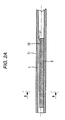
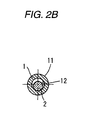
- a first tubular rack blank 1 is formed in a shape of a hollow cylinder so that each of an outer circumference 11 and a bore hole 12 has a circular cross-section.
- the first rack blank 1 is shaped so that both of the outer circumference 11 and the bore hole 12 have the circular cross-sections in the first embodiment, the shape of the cross-section of each of the outer circumference 11 and the bore hole 12 is not limited to a circle.
- a first tubular rack blank 1 having a bore hole, into which a second solid rack blank 2 is inserted, is used as a blank for forming a rack.
- the second rack blank 2 is formed in a shape of a solid cylinder.
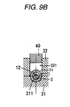
- a rack forming blank obtained by inserting the second rack blank 2 into the first rack blank 1 is put into between the lower die 31 and the upper die 32.
- a pressing surface (or restraining surface) 311 which is formed so that the width thereof is slightly narrower than the outer circumference 11 of the first rack blank 1 and which has a polygonal cross-sectional shape, is formed in the lower die 31.
- a guide hole 321 used to guide the punch 40 in an up-down direction is formed in the upper die 32.
- a rough rack teeth shaped portion 401 is formed in the bottom surface of the punch 40 substantially over the entire lateral length shown in FIG 3A .
- the rack teeth shaped portion 401 is pressed to the rack teeth forming portion of an outer circumference 11 of the first rack blank 11 to thereby form rough rack teeth (roughly processed rack teeth).
- An axial length L1 of the second rack blank 2 is set to be slightly longer than an axial length L2 of the rack teeth shaped portion 401 of the punch 40 (i.e., a length of the rack teeth formed in the first rack blank 1).
- an axial length L1 of a second rack blank 2 is at least equal to an axial length L2 of the rack teeth shaped portion 401 of the punch 40.
- a second rack blank 2 is disposed in a bore hole 12 of the first rack blank 1 to cover a rack teeth forming range formed in the first rack blank 1.
- a semicircular pressing surface (or restraining surface) 322 having the same cross-sectional shape as that of the outer circumference 11 of the first rack blank 1 on a part of the upper die 32 other than the guide hole 321.
- Four knockouts 33 are fit into the lower die 31 to be able to slide in an up-down direction. An upward pushing force is always provided to the knockouts 33 by a spring (not shown).
- the knockouts 33 press the punch 40 to the first rack blank 1 and support the first rack blank 1 from below by an upward pushing force when the rough rack teeth are formed in the first rack blank 1. Also, upon completion of performing the intermediate forming process, when the punch 40 rises, the knockouts 33 upwardly push the first rack blank 1 by the pushing force of the spring (not shown), and forcibly separate the rack teeth forming portion of the first rack blank 1 from the lower die 31.
- a thin-walled portion of the first hollow rack blank 1 has only to undergo plastic deformation.
- a forming weight can be low.
- gaps S 1, 51 are present between a side perpendicular to the rack teeth forming side of the bore hole 12 of the first rack blank 1 and the outer circumference 22 of the second rack blank 2. Consequently, the die is not put into a closed condition. Therefore, the forming load is small, so that the lifetime of the die is lengthened.
- gaps 52, 52 remain between the rack teeth forming side of the bore hole 12 of the first rack blank 1 and the outer circumference 22 of the second rack blank 2.
- the die is not put into a closed state. Therefore, the forming load is low. Consequently, the lifetime of the die is lengthened.
- the forming load is small, the cold forming of the rack is possible.
- the precision of forming the rack teeth is enhanced.
- the top surface 21 of the second rack blank 2 bites into the bore hole 12 of the first rack blank 1, so that the first rack blank 1 and the second rack blank 2 are integrated with each other.
- the rigidity of the entire formed rack teeth is increased.
- the blank material (or excess thickness material) excluded at the formation of the rack teeth 130 is caused to flow in a space between the bore hole 12 of the first rack 1 and the outer circumference 22 of the second rack blank 2.
- a dimensional relation between a gap B between the bore hole 12 of the first rack blank 1 and the top surface 21 of the second rack blank 2 and a dimension A of a bottom part of the rack teeth shaped portion 401 in the punch 40, which is pushed into the first rack blank 1 is set to be B ⁇ 0.7A.
- the rack teeth 130 can be formed at a low forming load.
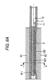
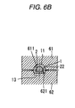
- the first rack blank 1, the intermediate forming process of which has been finished, is brought into a sizing-forming die illustrated in FIGS. 6A and 6B .
- the outer circumference of the first rack blank 1 is pressed between a semicircular pressing surface (or restraining surface) 611 formed on the bottom surface of the upper die 61 and a pressing surface 621 having a required rack teeth shaped portion, which is formed on the top surface of the lower die 62. Consequently, the required rack teeth (i.e., the finish-processed rack teeth) are formed while the width of the outer circumference at the side perpendicular to the rack teeth forming side of the first rack blank 1 is increased.
- the width between both sides of the outer circumference at the side perpendicular to the rack teeth side is set in the intermediate forming process to be narrower than the width between both sides of the outer circumference of the required rack teeth. Therefore, it is easy to input the first rack blank 1 to the sizing process. Also, even in a case where the die used in the sizing process has a simple structure including a pair of upper and lower dies, no burr protrudes to the outer circumference of the rack blank. Thus, the number of processes required to remove burrs is reduced.
- the first embodiment all the blank material (or excess thickness part) excluded at the formation of the rack teeth 130 is accommodated in the space between the bore hole 12 of the first rack blank 1 and the outer circumference 22 of the second rack blank 2.
- no burr is generated in the formed rack. Consequently, the number of processes required to remove burrs is reduced.
- the tubular rack blank is used, the part other than the rack teeth forming portion is lightened.
- the shape of the rear-side of the rack teeth is simple. Accordingly, the shape of the rack guide configured to guide the rear side of the rack teeth is simplified.
- the shape of the die is simple.
- the forming can be performed by a general purpose press.
- a die manufacturing const and a forming equipment cost can be reduced.
- a processing time is short.
- the sufficient thickness of the bottom of each of the rack teeth is assured.
- the strength of the rack teeth is enhanced.
- the second embodiment is an example which assures a gap between the bore hole 12 of the first rack blank 1 and the top surface 21 of the second rack blank 2 at the forming by forming teeth on the top surface 21 of the second rack blank 2. Consequently, the forming load is further reduced.
- the convex part of the top surface 21 enables the more efficient use of the blank material for the forming of the rack blank 130 of the first rack blank 1. Consequently, the filling degree, at which the teeth is filled with the blank material, is increased.
- the first tubular rack blank 1 of the second embodiment is formed like a hollow cylinder so that the cross-section of each of the outer circumference 11 and the bore hole 12 is circle.
- the first tubular rack blank 1 of the second embodiment has completely the same shape as that of the first rack blank 1 of the first embodiment.
- the second rack blank 2 to be inserted into the bore hole 12 is solid and cylindrical.
- each of the lower die 31, the upper die 32, the punch 40, and the knockouts 33 are the same as that of an associated component of the first embodiment.
- the axial length L1 of the second rack blank 2 is set to be slightly longer than the axial length L2 (i.e., the length of the rack teeth forming portion formed in the first rack blank 1) of the rack teeth shaped portion 401 of the punch 40.
- the second rack blank 2 is disposed in the bore hole 12 of the first rack blank 1 to cover a rack teeth forming range formed in the first rack blank 1. Also, the second rack blank 2 is disposed in the bore hole 12 of the first rack blank 1 so that the position of a concave part of the teeth 23 of the top surface 21 of the second rack blank 2 coincides with the position of a convex part of the teeth of the rack teeth shaped portion 401 of the punch 40.
- a thin-walled portion of the first hollow rack blank 1 has only to undergo plastic deformation.
- a forming weight can be low.
- gaps 51, 51 are present between a side perpendicular to the rack teeth forming side of the bore hole 12 of the first rack blank 1 and the outer circumference 22 of the second rack blank 2. Consequently, the die is not put into a closed condition. Accordingly, the forming load is small, so that the lifetime of the die is lengthened.
- a gap 24 is present between the concave part of the teeth 23 of the top surface 21 of the second rack blank 2 and the bore hole 12 of the first rack blank 1.
- the forming load is further smaller than the first embodiment.
- the inner circumference 12 of the first rack blank 1 bites into the teeth 23 of the top surface 21 of the second rack blank 2, so that the convex part of the teeth 23 serves to effectively cause the blank material to upwardly flow.
- the filling degree, at which the teeth are filled with the material is further enhanced, as compared with the first embodiment.
- gaps 52, 52 remain between the rack teeth forming side of the bore hole 12 of the first rack blank 1 and the outer circumference 22 of the second rack blank 2.
- the die is not put into a closed state. Therefore, the forming load is low. Consequently, the lifetime of the die is lengthened.
- the bore hole 12 of the first rack blank 1 bites into the top surface 21 of the second rack blank 2, so that the first rack blank 1 and the second rack blank 2 are integrated with each other.
- the rigidity of the entire formed rack teeth is increased.
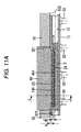
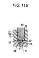
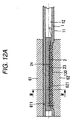
- the first rack blank 1, the intermediate forming process of which has been finished, is brought into a sizing-forming die illustrated in FIGS. 12B and 12A .
- the outer circumference of the first rack blank 1 is pressed between a semicircular pressing surface (or restraining surface) 611 formed on the bottom surface of the upper die 61 and a pressing surface 621 having a required rack teeth shaped portion, which is formed on the top surface of the lower die 62. Consequently, the required rack teeth (i.e., the finish-processed rack teeth) are formed while the width of the outer circumference at the side perpendicular to the rack teeth forming side of the first rack blank 1 is increased.
- the second rack blank 2 to be inserted into the bore hole 12 is solid and cylindrical in the second embodiment.
- the shape of the second rack blank 2 is not limited to the cylindrical shape.
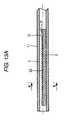
- flat surfaces 25, 25 are formed over the entire length of the second rack blank 2 on both sides of the outer circumference at the side perpendicular to the rack teeth forming side of the first rack blank 1, respectively.
- flat surfaces 25, 25 are formed over the entire length of the second rack blank 2 on both sides of the outer circumference at the side perpendicular to the rack teeth forming side of the first rack blank 1, respectively.
- the top surface 21 of the second rack 2 is also formed to be a flat surface.
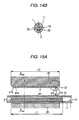
- FIGS. 15A to 22 a fifth embodiment of the invention is described with reference to FIGS. 15A to 22 .
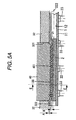
- the outer circumference 11 of the first rack blank 1 is restrained by the lower die 34.
- a punch 41 having a rough rack teeth shaped portion is pressed to a rack teeth forming portion formed on the outer circumference of the rack blank 1 to thereby form rough rack teeth (i.e., roughly processed rack teeth).
- the punch 41 is attached to a punch plate 42 of the bottom surface of an upwardly and downwardly movable ram (not shown) of a press machine.
- a rough rack teeth shaped portion 411 is formed substantially over the entire lateral length, as viewed in FIG 15A .
- first step processing is performed so that this rack teeth shaped portion 411 is pressed to the rack teeth forming portion of the outer circumference 11 of the rack blank 1 to thereby form rough rack teeth (i.e., roughly processed rack teeth).
- the axial length L1 of the second rack blank 2 is set to be slightly longer than an axial length L3 (i.e., a length of the rack teeth formed in the first rack blank 1) of the rack teeth shaped portion 411 of the punch 41.
- an axial length L1 of a second rack blank 2 is at least equal to an axial length L3 of the rack teeth shaped portion 411 of the punch 41.
- a second rack blank 2 is disposed in a bore hole 12 of the first rack blank 1 to cover a rack teeth forming range formed in the first rack blank 1.
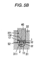
- Inclined restraining surfaces 341, 341 are formed on an upper side of the lower die 34.
- Parallel restraining surfaces 342, 342 are continuously formed by being connected to the lower sides of the inclined restraining surfaces 341, 341.
- the width W1 between the upward opening ends of the inclined restraining surfaces 341, 341 is set to be slightly larger than an outside dimension WO of the outer circumference 11 of the first rack blank 1.
- the width of the inclined restraining surface 341 linearly decreases toward a downward direction (i.e., a direction in which the punch 41 is pressed), as viewed in FIG 15B .
- the inclined restraining surface 341 is formed in parallel to a central axis of the first rack blank 1 by being tapered with respect to a perpendicular surface passing through the central axis of the first rack blank 1.
- a knockout 35 is fit between the parallel restraining surfaces 342, 342 to be able to slide in an up-down direction.
- An upward pushing force is always provided to the knockout 35 by a spring (not shown).
- the knockout 35 presses the punch 41 to the first rack blank 1 to form rough rack teeth in the first rack blank 1
- the knockout 35 supports the first rack blank 1 from below by an upward pushing force when the rough rack teeth are formed in the first rack blank 1.
- the knockout 35 upwardly pushes the first rack blank 1 by the pushing force of the spring (not shown), and forcibly separates the first rack blank 1 from the lower die 31.
- the rack teeth shaped portion 411 of the punch 41 used in the first step of the intermediate forming process is formed at a pressure angle ⁇ 2 (in the fifth embodiment of the invention, the a pressure angle ⁇ 2 is 10 degrees), which is less than the pressure angle (in the fifth embodiment of the invention, this pressure angle is 20 degrees).
- the strength and the durability of the punch 41 are enhanced by performing the rounding of the tooth bottoms 412 of the rack teeth shaped portion in the punch 41 used in the first step.
- the tooth bottoms 413, 413 at both lateral ends of the rack teeth shaped portion 411 are set so that a rounding dimension is larger than the rounding dimension of the tooth bottom 412 at the other portion. Consequently, the strength and the durability of the punch 41 are further enhanced.
- the rack teeth shaped portion 411 of the punch 41 used in the first step is set so that the pressure angle ⁇ 1 (i.e., the pressure angle at the side of the adjacent tooth 415) at the left side of a right end tooth 414, as viewed in FIG 15A , is 10 degrees.
- the inclination of the tooth form at the right side (i.e., the end-side tooth form) of the right-end tooth 414 is set so that an angle ⁇ 1 formed between a straight line (i.e., an axis line of the first rack blank 1) extending rightwardly and horizontally from the tooth edge of the tooth 414 and the right-side tooth form is 20 degrees.
- the left-end tooth 416 is formed to have the same shape as that of the right-end tooth 414, as viewed in FIG 15A .
- the strength and the durability of the punch 41 are enhanced by forming the teeth at both ends of the rack teeth shaped portion 411 into this shape. Further, the first rack blank 1 is suppressed from extending in the direction of an axis line thereof at the formation of the rough rack teeth. Consequently, the pitch precision of the formed rack teeth can be enhanced.
- the pressure angle ⁇ 1 of each of the left-end tooth 414 and the right-end tooth 415 ranges from 0 to 45 degrees. Preferably, the angle ⁇ 1 ranges from 5 degrees to 45 degrees.
- a thin-walled portion of the first hollow rack blank 1 has only to undergo plastic deformation.
- a forming weight can be low.
- a gap is present between a side perpendicular to the rack teeth forming side of the bore hole 12 of the first rack blank 1 and the outer circumference 22 of the second rack blank 2. Consequently, the die is not put into a closed condition. Therefore, the forming load is small, so that the lifetime of the die is lengthened.
- the forming load is small, the cold forming of the rack is possible.
- the precision of forming the rack teeth is enhanced.
- the top surface 21 of the second rack blank 2 bites into the bore hole 12 of the first rack blank 1, so that the first rack blank 1 and the second rack blank 2 are integrated with each other.
- the rigidity of the entire formed rack teeth is increased.
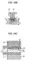
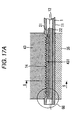
- FIGS. 17A and 17B When the first step of the intermediate forming process illustrated in FIGS. 16A and 16B is finished, as shown in FIGS. 17A and 17B , the outer circumference 11 of the first rack blank 1 is restrained by the lower die 34 having the same shape as shown in FIGS. 16A and 16B .
- Processing in a second step is performed, in which a punch 43 (which differs in rack teeth shaped portion from the punch 41 used in the first step) having a rough rack teeth shaped portion is pressed to the rack teeth forming portion formed in the outer circumference of the rack blank 1 and in which rough rack teeth (i.e., roughly processed rack teeth) are formed.
- a rack teeth shaped portion 431 is formed at a pressure angle ⁇ 3 (in the fifth embodiment of the invention, the pressure angle ⁇ 3 is 19.5 degrees), which is extremely close to the pressure angle (which is 20 degrees in the fifth embodiment of the invention) in the punch 43 used in the second step of the intermediate forming process.
- the rack teeth shaped portion 431 of the punch 43 is formed so that the tooth height thereof is slightly larger than the tooth height of the rack teeth which is a product.
- rack teeth 14 which are larger in tooth height and pressure angle than the rack teeth 13 formed in the first step (however, slightly larger in tooth height than the rack teeth of a finished product) and are formed due to this pushdown.
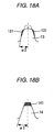
- FIG 18A illustrates the rack teeth 13 formed in the first step of the intermediate forming process.
- FIG 18B illustrates the rack teeth 14 formed in the second step of the intermediate forming process.
- excess blank materials 131, 131 are present in the rack teeth 13 formed in the first step so that addendum parts are thicker in the direction of a tooth thickness than the rack teeth to be formed as a finished product.
- the blank materials 131, 131 used in the first step are caused to flow in the direction of the tooth edge and are filled in the rack teeth 14 formed in the second step as the tooth edge blank material 141.
- the lower die 34 used in the first step and the second step of the intermediate forming process is formed so that the width W1 between the upper opening ends of the inclined restraining surfaces 341, 341 is slightly larger than the outside diameter dimension WO of the outer circumference 11 of the first rack blank 1.
- no restraining force acts in the direction of the width of the upper half of the rack blank 1.
- the upper half of the first rack blank 1 having undergone the first step and the second step of the intermediate forming process is formed so that a part having the width (i.e., the width between both sides perpendicular to the rack teeth forming side) of the tooth root of each of the rack teeth 13 and 14 outwardly protrudes in a radial direction from the outer circumference 11 of the first rack blank 1.
- the second step of the intermediate forming process processing is performed on the blank only to reduce the thickness of the rack teeth so that the pressure angle thereof is made to be closer to the pressure angle of the rack teeth serving as a product, and that the tooth height is increased.
- the forming load is small.
- the width of the tooth root of each of the rack teeth 13 and 14 is not restrained. Accordingly, the die is not put into a closed state. Therefore, the forming load is small, so that the lifetime of the die is lengthened.
- the first rack blank 1 having undergone the second step of the intermediate forming process is brought into the sizing-forming die illustrated in FIGS. 20A and 20B .
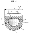
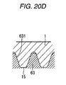
- the outer circumference of the first rack blank 1 is pressed between the semicircular pressing surface (i.e., the restraining surface) 611 formed on the bottom surface of an upper die 61 and a required rack teeth shaped portion 631 formed in the top surface of a lower die 63. Consequently, the required rack teeth (i.e., the finish-processed rack teeth) 15 are formed while the width of the tooth root of each of the rack teeth of the first rack blank 1 is reduced.
- the width of the tooth root of each of the rack teeth 14 of the first rack blank 1 is made to be larger than the width of each of the required rack teeth. Accordingly, the width of the tooth root of each of the rack teeth 14 of the first rack blank 1 is restrained by arc shaped restraining surfaces 632, 622 formed on both sides of the rack teeth shaped portion 631 of the lower die 63 to form the rack teeth 14 so that the width of the tooth root of each of the rack teeth 14 is set to be the width of each of the (circular-arc-like) required rack teeth (i.e., the finish-processed rack teeth) 15.
- FIG 22 illustrates the rack teeth 15 at the end of the forming in the first step of the sizing process. As shown in FIG 22 , slight rounding is performed on corner portions (at both of the tooth edge side and the tooth width side) of each of the rack teeth 15 in the first step of the sizing process to thereby enhance the strength of the rack teeth 15.
- the tooth height of each of the rack teeth 14 of the first rack blank 1 formed in the second step of the intermediate forming process is set to be larger than the tooth height of the required rack teeth. Therefore, a gap is assured between the tooth edges of the rack teeth shaped portion 631 of the lower die 63 and the bottoms of the rack teeth 14 of the lower die 63. Thus, the die is not put into a closed condition. Accordingly, the forming load is small, so that the lifetime of the die is lengthened.
- the first rack blank 1 having undergone the first step of the sizing process is brought into the sizing-forming die illustrated in FIGS. 21A and 21B .
- the outer circumference of the first rack blank 1 is pressed between the semicircular pressing surface (i.e., the restraining surface) 611 formed on the bottom surface of an upper die 61 and a required rack teeth shaped portion 641 formed in the top surface of a lower die 64. Consequently, the required rack teeth (i.e., the finish-processed rack teeth) 16 are formed in the first rack blank 1.
- the lower die 64 does not restrain the width of each of the rack teeth 15 of the first rack blank 1. Additionally, a gap is assured between the tooth edges of the rack teeth shaped portion 641 of the lower die 64 and the tooth bottoms of the rack teeth 15. Thus, the die is not put into a closed condition. Accordingly, the forming load is small, so that the lifetime of the die is lengthened.
- all the blank material (or excess thickness part) excluded at the formation of the rack teeth is accommodated in the space between the bore hole 12 of the first rack blank 1 and the outer circumference 22 of the second rack blank 2.
- no burr is generated in the formed rack. Consequently, the number of processes required to remove burrs is reduced.
- the tubular rack blank is used, the part other than the rack teeth forming portion is lightened.
- the shape of the rear-side of the rack teeth is simple. Accordingly, the shape of the rack guide configured to guide the rear side of the rack teeth is simplified.
- the shape of the die is simple.
- the forming can be performed by a general purpose press.
- a die manufacturing const and a forming equipment cost can be reduced.
- a processing time is short.
- the sufficient thickness of the bottom of each of the rack teeth is assured.
- the strength of the rack teeth is enhanced.
- the second rack blanks used in the first to fourth embodiments can also be used as the second rack blank of the fifth embodiment.
- the sixth embodiment is an example in which a mandrel serving as a processing jig is used instead of the second rack blank 2, and in which the mandrel is extracted from the first rack blank 1 upon completion of forming, to thereby lighten the rack.
- the first tubular rack blank of the sixth embodiment is formed like a hollow cylinder so that the shape of the cross section of each of the outer circumference 11 and the bore hole 12 is a circle.
- the first tubular rack blank of the sixth embodiment has completely the same shape of the first rack blank of the fifth embodiment.
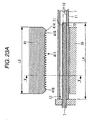
- a blank obtained by inserting a solid mandrel 7 into the bore hole 12 of the first tubular rack blank 1 is used as a rack forming blank.
- the mandrel 7 of the fifth embodiment is formed like a solid cylinder.
- the top surface 71 of the mandrel 7 is formed like a flat surface over the entire axial length.
- a rack forming blank obtained by inserting the mandrel 7 thereinto from a left-end-side opening portion 17 of the first rack blank 1 is prepared.
- the outer circumference 11 of the first rack blank 1 is restrained by the lower die 34.
- a punch 41 having a rough rack teeth shaped portion is pressed to a rack teeth forming portion in the outer circumference of the rack blank 1 to thereby form a rough rack teeth (i.e., roughly processed rack teeth).
- An axial length L4 of the mandrel 7 is set to be slightly larger than the axial length (i.e., the length of the rack teeth forming portion formed in the first rack blank 1) L3.
- the axial length L4 of the mandrel 7 is at least equal to the axial length L3 of the rack teeth shaped portion 411 of the punch 41. Then, the mandrel 7 is disposed in the bore hole 12 of the first rack blank 1 to cover a rack teeth forming range formed in the first rack blank 1.
- the shapes of the punch 41, the lower die 34, and the knockout 35 is the same as the shapes of those of the fifth embodiment, respectively.
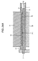
- the punch 41 When the punch 41 is downwardly pushed, the outer circumference 11 of the first rack blank 1 is downwardly pushed by the rack teeth shaped portion 411 of the punch 41.
- the rack teeth 13 are formed in the outer circumference 11 of the first rack blank 1, which is at the side of the punch 41, so that the bore hole 12 of the first rack blank 1 abuts against the flat-surface-like top surface 71 (i.e., a surface facing the rack teeth forming side of the first rack blank 1) of the mandrel 7.
- the mandrel 7 is once extracted from the left-end-side opening portion 17 of the first rack blank 1. Then, the first rack blank 1 is brought into the die to be used in the second step illustrated in FIG 24B . Subsequently, the mandrel 7 is inserted from the left-end-side opening portion 17 of the first rack blank 1.
- the outer circumference 11 of the first rack blank 1 is restrained by the lower die 34 (not shown), which has the same shape as that illustrated in FIG 24A .
- the punch 43 (which differs in the rack teeth shaped portion from the punch 41 used in the first step) is pressed to the rack teeth forming portion provided in the outer circumference of the rack blank 1. Then, processing to be performed in the second step for forming rough rack teeth (i.e., the roughly processed rack teeth) is performed.
- the shape of the punch 43 used in the second step of the intermediate forming process is the same as that of the punch used in the fifth embodiment.
- the mandrel 7 is once extracted from the left-end-side opening portion 17 of the first rack blank 1. Then, the first rack blank 1 is brought into the die used in the sizing process illustrated in FIGS. 25A and 25B . Subsequently, the mandrel 7 is again inserted thereinto from the left-end-side opening portion 17 of the first rack blank 1.
- the outer circumference 11 of the first rack blank 1 is pressed between the semicircular pressing surface (or restraining surface) 611 formed on the bottom surface of the upper die 61 of the die illustrated in FIGS. 25A and 25B for sizing, and the required rack teeth shaped portion 631 formed in the top surface of the lower die 63 thereof. Consequently, the required rack teeth (i.e., the finish-processed rack teeth) 15 are formed while the width of the tooth root of each of the rack teeth of the first rack blank 1 is narrowed.
- the shapes of the upper die 61 and the lower die 63 are the same as those of the corresponding dies according to the fifth embodiment.
- the mandrel 7 is once extracted from the left-end-side opening portion 17 of the first rack blank 1. Then, the first rack blank 1 is brought into the die used in the second step of the sizing process illustrated in FIGS. 26A and 26B . Subsequently, the mandrel 7 is again inserted thereinto from the left-end-side opening portion 17 of the first rack blank 1.
- the outer circumference 11 of the first rack blank 1 is pressed between the semicircular pressing surface (or restraining surface) 611 formed on the bottom surface of the upper die 61 of the die illustrated in FIGS. 26A and 26B for sizing-forming, and the required rack teeth shaped portion 631 formed in the top surface of the lower die 63 thereof. Consequently, the required rack teeth (i.e., the finish-processed rack teeth) 15 are formed while the width of the tooth root of each of the rack teeth of the first rack blank 1 is narrowed.
- the shapes of the upper die 61 and the lower die 64 are the same as those of the corresponding dies according to the fifth embodiment.
- the mandrel 7 is extracted form the left-end-side opening portion 17.
- the entire forming process is finished.
- the mandrel 7 may be extracted from the rack blank 1 only when the second step of the sizing process, which is the last step, is finished, without being extracted every finish of each forming step.
- the mandrel 7 is extracted from the bore hole 12 of the first rack blank 1, so that a rack, which is a finish product, is lightened.
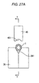
- a seventh embodiment will be described with reference to FIGS. 27A to 31 .
- the seventh embodiment uses the same first rack blank 1 as that used in the first embodiment.
- the cross-sectional shape of the first rack blank is not limited to a cylinder. Even cross-sectionally rectangular or polygonal first rack blank can be used. Alternatively, even a first rack blank, which is formed so that the shape of the outer circumferential surface thereof differs form the shape of the inner circumferential surface thereof, can be used.
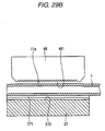
- the first rack blank 1 is set between a U-shaped groove punch 45 and a tapered die 36. Then, the first rack blank 1 is pressed by the U-shaped groove punch 45, so that the first rack blank 1 is pushed into the tapered die 36. Consequently, the tapered portion 11a is formed in the first rack blank 1 according to the shapes of the U-shaped groove punch 45 and the tapered die 36.
- a tapered surface 361 for forming the tapered portion 11a in the first rack blank 1 is formed along the longitudinal direction of the top portion of the tapered die 36 with a cross-section thereof being substantially V-shaped.
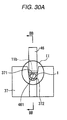
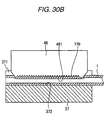
- the rack blank 1, in which the tapered portion 11a is formed is set between the teeth form punch 46 and the lower die 37 so that the tapered portion 11a is directed toward the teeth form punch 46.
- the teeth form punch 46 is pressed to the tapered portion 11a of the first rack blank 1, so that the first rack blank 1 is pushed into the lower die 37. Consequently, the rack teeth 11b are formed in the tapered portion 11a of the first rack blank 1 according to the shapes of the teeth form punch 46 and the lower die 37.
- the tapered portion 11a prevents an excess thickness part (or material) from being generated in the gap portion (see a part 54 shown in FIG 31 ) between the teeth form punch 46 and the lower die 37.
- this embodiment can deal with rack teeth having various shapes by adjusting the angle at the tapered portion 11a.
- rack teeth shaped portion 461 are formed in the bottom portion of the teeth form punch 46 along the longitudinal direction thereof.
- tapered surfaces 371, 371 upwardly extending from both lateral end portions of this U-shaped groove 372 are formed in the lower die 37.
- the steering rack manufacturing method for manufacturing the steering rack according to the seventh embodiment includes a step of using the first rack blank 1 as the rack blank, and forming the tapered shape part 10a in a portion in which the rack teeth 11b of the first rack blank 1 is formed, using the dies 45 and 36, and a step of pressing the punch 46 having the rack teeth form 461 to the portion of the first rack blank 1, in which the tapered portion 10a is formed, to thereby form the rack teeth 11b.
- the length of the portion, to which the rack teeth shaped portion 461 of the punch 46 is pressed can be increased. Consequently, the forming of the rack teeth 11b can be facilitated.
- the tapered shape part 10a of the first rack blank 1 can be prevented from generating the excess thickness material at the forming of the rack teeth 11b. Additionally, the rack teeth 11b can sufficiently be filled with the material. Moreover, the processing step of removing a burr can be eliminated. Accordingly, the manufacturing cost can be reduced.
- sealed forming is prevented from being performed in any of all the steps thereof.
- forming stress can be suppressed to low level. Consequently, the lifetime of each of the dies 45, 36, 46, and 37 can be lengthened. Accordingly, the manufacturing cost can be reduced.
- the steering rack can be formed by cold-forging, the precision in forming the rack teeth 11b can be enhanced, as compared with the case of performing warm-forging.
- the shapes of the dies 45, 36, 46, and 37 are simple.
- the steering rack can be formed by a general-purpose press. Consequently, the die manufacturing const and the forming equipment cost can be reduced. Accordingly, the manufacturing cost can be reduced.
- FIGS. 27A , 28B , 32A , and 33B The components of the eighth embodiment are the same as or equivalent to those of the seventh embodiment are designated by the same reference numerals in the drawings. The description of such components will be omitted or simplified.
- the first rack blank 1 is set between the U-shaped groove punch 45 and the tapered die 36. Then, the first rack blank 1 is pressed by the U-shaped groove punch 45, so that the first rack blank 1 is pushed into the tapered die 36. Consequently, the tapered portion 11a is formed in the first rack blank 1 according to the shapes of the U-shaped groove punch 45 and the tapered die 36.
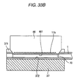
- a core member 70 whose diameter is less than the inside diameter of the first rack blank 1, is inserted into the tapered portion 11a of the first rack blank 1.
- a mandrel can be inserted, instead of the core member 70.
- the first rack blank 1 in which the tapered portion 11a is formed and into which the core member 70 is inserted, is set between a teeth form punch 46 and the lower die 37 so that the tapered portion 11a is directed toward the teeth punch 46.
- the teeth form punch 46 is pressed to the tapered portion 11a of the first rack blank 1, so that the first rack blank 1 is pushed into the lower die 37. Consequently, the rack teeth 11b is formed in the tapered portion 11a of the first rack blank 1 according to the shapes of the teeth form punch 46 and the lower die 37.
- the manufacturing method for the steering rack of the eighth embodiment includes the step of using the first tubular rack blank 1 as the rack blank according to the invention and forming the tapered shape 10a in the part of the first rack blank 1, in which the rack teeth 11b are formed using the dies 45 and 36, the step of inserting the core member 70, whose diameter is less than that of the first rack blank 1, into the part of the first rack blank 1, in which the tapered shape 10a is formed, and the step of holding the punch 46 having a rack teeth shaped portion 461 to the part of the first rack blank 1, in which the tapered shape 10a is formed, to form the rack teeth 11b.
- the strength of the rack can be enhanced.
- the strength of the rack can be adjusted by changing the material of the core member 70.
- the other composing-elements and advantages are similar to those of the seventh embodiment.
- the seventh and eighth embodiments can be configured so that a sizing process is added after the process of forming the rack teeth in the tapered part of the first rack blank, similarly to the other embodiments. Also, the second rack blank in each of the first to fourth embodiments can appropriately be used as the core member in the eighth embodiment.
- the material of the second rack blank can be the same as and differ from that of the first rack material.
- the second rack blank or the mandrel is solid in all the aforementioned embodiments, the second rack blank or the mandrel can be formed to be hollow.
- a steering rack and a manufacturing method of the steering rack in which the steering rack is lightweight, a the filling degree of a material with which teeth are filled is enhanced, and the rigidity of the entire rack teeth is improved.
Landscapes
- Engineering & Computer Science (AREA)
- Mechanical Engineering (AREA)
- Chemical & Material Sciences (AREA)
- Combustion & Propulsion (AREA)
- Transportation (AREA)
- Forging (AREA)
- Gears, Cams (AREA)
Abstract
Description
- The present invention relates to a steering rack and to a method of manufacturing the same.
- Conventionally, in a method of manufacturing a steering rack, rack teeth have been formed by cutting a blank. However, in recent years, steering racks tend to be formed by plastic working using a die for the purpose of reducing cost.
- For example,
JP-A-10-58081 JP-A-2001-79639 -
JP-B2-3442298 reference numeral 21 inFIG 12 ofJP-A-2004-34829 - Moreover, in the manufacturing methods disclosed in
JP-A-10-58081 JP-A-2001-79639 JP-B2-3442298 -
JP-B2-3-5892 JP-B2-2928427 US-B2-6575009 , andJP-A-2002-178095 - It is an object of one or more embodiments of the present invention to provide a steering rack and a method of manufacturing the same, in which the steering rack is lightweight, and a shape of an associated die is simple and has a long lifetime, a manufacturing cost is reduced, filling degree of a material within a teeth shape is improved, and a rigidity of entire rack teeth is enhanced.
- According to one or more embodiments of the invention, a method of manufacturing a steering rack includes providing a first rack blank in a form of a pipe having a bore hole, and a second rack blank or a mandrel having such a cross-sectional shape that a gap is provided between the second rack blank or the mandrel and an inner circumferential surface of the first rack blank, inserting the second rack blank or the mandrel into the bore hole of the first rack blank, restraining an outer circumferential surface of the first rack blank other than a rack teeth forming portion of the first rack blank by a first die, forming rack teeth on the first rack blank by pressing a punch having a rack teeth shaped portion onto the rack teeth forming portion of the first rack blank, and causing the first rack blank to contact an outer circumferential surface of the second rack blank or the mandrel facing the rack teeth forming portion of the first rack blank, and allowing a blank material, which has been excluded in the forming the rack teeth, to flow into the gap between the inner circumferential surface of the first rack blank and the second rack blank or the mandrel such that the blank material is accommodated in the gap.
- According to one or more embodiments of the invention, the providing the first rack blank and the second rack blank or the mandrel includes providing the first rack blank having a hollow cylindrical shape.
- According to one or more embodiments of the invention, the providing the first rack blank and the second rack blank or the mandrel includes providing the second rack blank which is solid.
- According to one or more embodiments of the invention, the providing the first rack blank and the second rack blank or the mandrel further includes providing the second rack blank having a cylindrical shape.
- According to one or more embodiments of the invention, the providing the first rack blank and the second rack blank or the mandrel includes providing the second rack blank having an axial length which is equal to or longer than a length of the rack teeth forming portion of the first rack blank.
- According to one or more embodiments of the invention, the providing the first rack blank and the second rack blank or the mandrel includes forming teeth on the outer circumferential surface of the second rack blank facing the rack teeth forming portion of the first rack blank at a pitch equal to a pitch of the rack teeth shaped portion of the punch..
- According to one or more embodiments of the invention, the method further includes, after the allowing the blank material, which has been excluded, to flow into the gap such that the blank material is accommodated in the gap, sizing the rack teeth to obtain a required rack teeth by holding and pressing the first rack blank between a second die having a required rack teeth shaped portion and a third die having an outer circumference corresponding to a required shape of the outer circumferential surface of the first rack blank other than the rack teeth forming portion.
- According to one or more embodiments of the invention, the sizing the rack teeth includes forming the required rack teeth while narrowing a tooth width of a root of the rack teeth to a required tooth width.
- According to one or more embodiments of the invention, the method further includes, after the sizing the rack teeth, extracting the mandrel from the bore hole of the first rack blank.
- According to one or more embodiments of the invention, the forming the rack teeth includes firstly forming the rack teeth by a first punch formed with a first rack teeth shaped portion having a pressure angle that is smaller than a pressure angle of a required rack teeth shape, and secondly forming the rack teeth by a second punch formed with a rack teeth shaped portion having a pressure angle that is closer to the pressure angle of the required rack teeth shape than the pressure angle of the first rack teeth shaped portion.
- According to one or more embodiments of the invention, the sizing the rack teeth includes: firstly forming the required rack teeth while narrowing the width of the root of the rack teeth formed on the first rack blank to the required width, and secondly forming the required rack teeth without restraining the tooth width of the root of the rack teeth formed on the first rack blank.
- According to one or more embodiments of the invention, the forming the rack teeth includes forming the rack teeth having a tooth height which is larger than a tooth height of a required rack teeth shape.
- According to one or more embodiments of the invention, the forming the rack teeth includes forming the rack teeth by the punch having the rack teeth shaped portion such that a pressure angle of a rack tooth shape at each end in an axial direction of the first rack blank is 0 degree to 45 degrees on a side of an adjacent rack tooth shape and such that an angle formed between the rack tooth shape and an axis of the first rack blank on a side of the respective ends is 5 degrees to 45 degrees.
- According to one or more embodiments of the invention, the restraining the first rack blank by the first die includes restraining the first rack blank by a pair of restraining surfaces of the first die, wherein the pair of restraining surfaces is formed in such a tapered shape that a width between the restraining surfaces continuously decreases toward a direction in which the punch is pressed.
- According to one or more embodiments of the invention, the providing the first rack blank and the second rack blank or the mandrel includes providing the mandrel which is solid and having a cylindrical shape, wherein the surface of the mandrel facing the rack teeth forming portion of the first rack blank is flat along a length the rack teeth forming portion.
- According to one or more embodiments of the invention, the method further includes, before the restraining the first rack blank by the first die, forming a tapered part on the rack teeth forming portion of the first rack blank.
- According to one or more embodiments of the invention, a method of manufacturing a steering rack includes providing a first rack blank, forming a tapered part ion a rack teeth forming portion of the first rack blank, and forming rack teeth by pressing a punch having a rack teeth shaped portion onto the rack teeth forming portion of the first rack blank on which the tapered part is formed.
- According to one or more embodiments of the invention, the method further includes, before the forming the rack teeth, inserting a second rack blank or a mandrel having a diameter that is less than an inner diameter of the first rack blank into the first rack blank at the rack teeth forming portion.
- According to one or more embodiments of the invention, there is provided a steering rack manufactured by one of the aforementioned manufacturing methods.
- According to one or more embodiments of the invention, a steering rack includes a first rack blank in a form of a pipe having a bore hole, and a second rack blank inserted into the bore hole of the first rack blank. Rack teeth are formed on an outer circumferential surface of the first rack blank, and an inner circumferential surface of a rack teeth forming portion of the first rack blank is attached to the second rack blank such that the first rack blank bites into the second rack blank due to plastic deformation.
- According to one or more embodiments of the invention, an axial length of the second rack blank is equal to or longer than a length of the rack teeth forming portion of the first rack blank.
- According to one or more embodiments of the invention, teeth are formed on an outer circumferential surface of the second rack blank at a pitch that is equal to a pitch of the rack teeth of the first rack blank.
- In the method of manufacturing a steering rack and the steering rack manufactured by the method according to one or more embodiments of the invention, there are used the first rack blank in a form of the pipe having the bore hole, and the second rack blank having such a cross-sectional shape that the gap is provided in the bore hole between the first rack blank and a side of the second rack blank perpendicular to the rack teeth forming portion of the first rack blank.
- Therefore, the blank material excluded in the formation of the rack teeth is caused to flow in the space between the bore hole of the first rack blank and the outer circumference of the second rack blank, and to be accommodated in the space. Further, the gap remains in the bore hole. Thus, the die is not brought into a closed condition, and the forming load is small. Thus, the lifetime of the die is lengthened. Further, the small forming load enables the cold forming of the rack. Accordingly, precision in forming the rack teeth is enhanced.
- The bore hole of the first rack blank abuts against the second rack blank. The reaction force enables the effective use of the blank material in forming the rack teeth of the first rack blank. The filling degree, at which the teeth are filled with the material, is enhanced. The second rack blank bites into the bore hole surface of the first rack blank, so that the first rack blank and the second rack blank are joined together. Consequently, the rigidity of the entire rack teeth is enhanced.
- Further, the blank material excluded in the formation of the rack teeth is caused to flow in the bore hole of the rack blank and to be accommodated in the bore hole. Thus, no burr is generated in the formed rack so that the number of processes required to remove burrs is reduced. Also, the shape of the die is simple, so that the rack can be formed by a general-purpose press. Thus, a die manufacturing cost and a forming equipment cost can be reduced. Because the mandrel may not be used, a processing time is short.
- In the method of manufacturing a steering rack and the steering rack manufactured by the method according to one or more embodiments of the invention, the axial length of the second rack blank may be equal to the length of the rack teeth forming portion of the first rack blank. Therefore, portions other than the rack teeth forming portion can be lightened so that a process of drilling a hole to lighten the rack can be omitted.
- In the method of manufacturing a steering rack and the steering rack manufactured by the method according to one or more embodiments of the invention, the teeth are formed on an outer circumferential surface of the second rack blank, which faces the rack teeth forming portion of the first rack blank, at a pitch that is equal to the pitch of the rack teeth shaped portion of the punch. Thus, an additional gap is provided between a concave part of the teeth of the second rack blank and the bore hole of the first rack blank, so that the forming load can be further reduced.
- Also, a convex part of the teeth of the second rack blank pushes the blank material toward the rack teeth forming side of the first rack blank. Thus, the blank material is caused to more effectively flow to the rack teeth. Consequently, the filling degree, at which the teeth are filled with the material, is enhanced.
- In the method of manufacturing a steering rack and the steering rack manufactured by the method according to one or more embodiments of the invention, in the intermediate forming process, the width between respective sides of the outer circumference perpendicular to a side of the rack teeth forming portion is formed narrower than the width between the respective sides of the outer circumference of the required rack teeth shape, and in the sizing process, the rack teeth are formed to have a certain width.
- Accordingly, it is easy to put the rack blank into the sizing process. Additionally, even in a case where the die used in the sizing process has a simple structure with a pair of upper and lower dies, no burr protrudes to the outer circumference of the rack blank. Thus, the number of processes required to remove burrs is reduced.
- In the method of manufacturing a steering rack and the steering rack manufactured by the method according to one or more embodiments of the invention, there are used the first rack blank in the form of the pipe having the bore hole, and the second rack blank which is inserted into the bore hole of the first rack blank and has such a cross-sectional shape that the gap is provided in the bore hole of the first rack blank between the first rack blank and a side of the second rack blank perpendicular to the rack teeth forming portion of the first rack blank when forming the rack teeth.
- Additionally, the punch having a rough rack teeth shaped portion is pressed to the rack teeth forming portion of the outer circumference of the first rack blank. Thus, the bore hole surface of the firs track blank is caused to abut against the outer circumference of the second rack blank. Also, the tooth width of the root of the rack teeth protrudes from the outer circumference of the first rack blank. Thus, the rough rack teeth are formed in the intermediate forming process. Subsequently, upon completion of performing the intermediate forming process, the first rack blank is pressed between the die having the required rack teeth shaped portion, and the die having the required outer circumference shape at the side facing the rack teeth forming side, while the outer circumference of the first rack blank is sandwiched. Thus, the required rack teeth are formed by the sizing process, while the tooth width of the root of each of the rack teeth is decreased to the required tooth width of the rack blank.
- Accordingly, all the blank material excluded at the formation of the rack teeth is accommodated in the space between the bore hole surface of the first rack blank and the outer circumference of the second rack blank. Also, the gap remains in this bore hole. Additionally, the width of the tooth root of the rack is not restrained in the intermediate forming process. Thus, the die is not put into a close condition. The forming load is small. Consequently, the lifetime of the die is lengthened. Further, the small forming load enables the cold forming of the rack.
- The bore hole surface of the first rack blank abuts against the second rack blank. The reaction force enables the effective use of the blank material in forming the rack teeth in the first rack blank. The filling degree, at which the teeth are filled with the material, is enhanced. The second rack blank bites into the bore hole of the first rack blank, so that the first rack blank and the second rack blank are integrated with each other. Consequently, the rigidity of the entire formed rack blank is enhanced.
- Further, the blank material excluded at the formation of the rack teeth is caused to flow in the bore hole of the rack blank and to be accommodated in the bore hole. Thus, no burr is generated in the formed rack. The number of processes required to remove burrs is reduced. Also, the shape of the die is simple, so that the rack can be formed by a general-purpose press. Thus, a die manufacturing const and a forming equipment cost can be reduced. Because no mandrel is used, a processing time is short.
- In the method of manufacturing a steering rack and the steering rack manufactured by the method according to one or more embodiments of the invention, the mandrel is extracted from the bore hole of the first rack blank after the step of sizing the rack teeth is finished. Thus, the rack serving as a finished product is lightened.
- Also, in the case of the steering rack manufacturing method according to one or more embodiments of the invention, and the steering rack manufactured by such a steering rack manufacturing method, the intermediate forming process includes a first forming step of forming the rough rack teeth by a punch, whose pressure angle is smaller than a pressure angle of a required rack teeth shaped portion, and a second forming step of forming the rack teeth by a punch in which a rack teeth shaped portion having a pressure angle that is closer to a pressure angle of the required rack teeth shaped portion than the pressure angle of the first rack teeth shaped portion, is formed.
- Accordingly, in the first step, an amount of blank material needed for forming the rack teeth having a finished product shape can be assured at a small forming load. In the second step, the rack teeth can be formed at a further small forming load into a shape according to which the blank can easily be led to the sizing process.
- In the method of manufacturing a steering rack and the steering rack manufactured by the method according to one or more embodiments of the invention, the step of sizing the rack teeth includes a first step of forming the required rack teeth by narrowing a width of a tooth root of each of the rack teeth formed in the first rack blank to a required tooth width, and a second step of forming the required rack teeth without restraining the width of the tooth root of each of the rack teeth formed in the first rack blank.
- Therefore, the forming in the direction of the tooth width and the forming in the direction of a tooth trace are performed separately from each other. Thus, the forming load is small. The profile precision of a tooth surface and the uniformity of the tooth forms are enhanced.
- In the method of manufacturing a steering rack and the steering rack manufactured by the method according to one or more embodiments of the invention, in the intermediate forming process, rough rack teeth having a tooth height, which is larger than a tooth height of the required rack teeth shaped portion, are formed.
- Therefore, in the sizing process, a gap is assured between the edge and the bottom of each of the rack teeth. The die is not put into a closed condition. Accordingly, a tooth flank pressure rises at a small forming load, so that the precision of a tooth flank is enhanced.
- In the method of manufacturing a steering rack and the steering rack manufactured by the method according to one or more embodiments of the invention, a punch used in the intermediate forming process is formed so that a pressure angle of each of tooth forms respectively provided at both ends in a direction along an axis line of the first rack blank ranges from 0 to 45 degrees at an adjacent rack tooth side, and that an angle formed between the tooth form at an end side and the axis line of the first rack blank ranges from 5 degrees to 45 degrees.
- Thus, the strength and the durability of the punch are enhanced. Also, the first rack blank can be suppressed from extending in the direction of an axis line at the formation of the rough rack teeth. Additionally, the pitch precision of the formed rack teeth can be enhanced.
- In the method of manufacturing a steering rack and the steering rack manufactured by the method according to one or more embodiments of the invention, the manufacturing method includes a step of forming a tapered part in a rack teeth forming portion of the first rack blank, and a step of forming rack teeth by pressing a punch having a rack teeth shaped portion to the rack teeth forming portion of the first rack blank, in which the tapered part is formed. This can facilitate the formation of the rack teeth and can prevent an excess thickness part from being generated at the formation of the rack teeth. Thus, the rack teeth can fully be filled with the material. Also, the manufacturing cost can be reduced.
-
-
FIG 1A is an explanatory view illustrating a first tubular rack blank for first embodiment of the invention. -
FIG 1B is a cross-sectional view taken along the line A-A shown inFIG. 1A . -
FIG 2A is an explanatory view of the first embodiment, and illustrates a state in which a second solid rack blank is inserted into a bore hole of the first rack blank shown inFIG 1A . -
FIG 2B is a cross-sectional view taken along the line B-B shown inFIG 2A . -
FIG 3A is a process view illustrating a manufacturing method of a rack according to the first embodiment and is an explanatory view illustrating a state in which a first tubular rack blank is attached to a die used in an intermediate forming process of forming a rough rack. -
FIG 3B is a cross-sectional view taken along the line C-C shown inFIG 3A . -
FIG 4A is an explanatory view illustrating a halfway state in forming in the intermediate forming process. -
FIG 4B is a cross-sectional view taken along the line D-D shown inFIG 4A . -
FIG 5A is an explanatory view illustrating a state at the end of the forming in the intermediate forming process. -
FIG 5B is a cross-sectional view taken along the line E-E shown inFIG 5A . -
FIG 6A is a process view illustrating a post-process after the state shown inFIG 5A and is an explanatory view illustrating a sizing process of forming required rack teeth. -
FIG 6B is a cross-sectional view taken along the line F-F shown inFIG 6A . -
FIG 7A is an explanatory view illustrating a second tubular rack blank for second embodiment of the invention. -
FIG 7B is a cross-sectional view taken along the line G-G shown inFIG 7A . -
FIG 8A is an explanatory view of the second embodiment, and illustrates a state in which a second uneven solid rack blank is inserted into a bore hole of the first rack blank shown inFIG 7A . -
FIG 8B is a cross-sectional view taken along the line H-H shown inFIG 8A . -
FIG 9A is a process view illustrating a manufacturing method of a rack according to the second embodiment and is an explanatory view illustrating a state in which the first tubular rack blank is attached to a die used in an intermediate forming process of forming a rough rack. -
FIG 9B is a cross-sectional view taken along the line J-J shown inFIG 9A . -
FIG 10A is an explanatory view illustrating a halfway state in forming in the intermediate forming process. -
FIG 10B is a cross-sectional view taken along the line K-K shown inFIG 10A . -
FIG 11A is an explanatory view illustrating a state at the end of the forming in the intermediate forming process. -
FIG 11B is a cross-sectional view taken along the line L-L shown inFIG 11A . -
FIG 12A is a process view illustrating a post-process after the state shown inFIG 11A and is an explanatory view illustrating a sizing process of forming required rack teeth. -
FIG 12B is a cross-sectional view taken along the line M-M shown inFIG 12A . -
FIG 13A is an explanatory view of a third embodiment, and illustrates a modification of the second uneven solid rack blank to be inserted into the bore hole of the first rack blank. -
FIG 13B is a cross-sectional view taken along the line N-N shown inFIG 13A . -
FIG 14A is an explanatory view of a fourth embodiment, and illustrates a modification of the second uneven solid rack blank to be inserted into the bore hole of the first rack blank. -
FIG 14B is a cross-sectional view taken along the line P-P shown inFIG 14A . -
FIG 15A is a process view illustrating a manufacturing method of a rack according to fifth embodiment and is an explanatory view illustrating a state in which a first tubular rack blank having a bore hole, into which a second solid rack blank is inserted, is attached to a die used in a first step of an intermediate forming process of forming a rough rack. -
FIG 15B is a cross-sectional view taken along the line Q-Q shown inFIG 15A . -
FIG 15C is an enlarged cross-sectional view of a part EE shown inFIG 15A . -
FIG 16A is an explanatory view illustrating a state at the end of the forming in the first step of the intermediate forming process. -
FIG 16B is a cross-sectional view taken along the line R-R shown inFIG 16A . -
FIG 16C is an enlarged cross-sectional view of a part FF shown inFIG 16A . -
FIG 17A is an explanatory view illustrating a state at the end of the forming in a second step of the intermediate forming process which is a post-process after the state shown inFIG 16A . -
FIG 17B is a cross-sectional view taken along the line S-S shown inFIG 17A . -
FIG 17C is an enlarged cross-sectional view of a part GG shown inFIG 17A . -
FIG 18A illustrates rack teeth formed in the first step of the intermediate forming process. -
FIG 18B illustrates rack teeth formed in the second step of the intermediate forming process. -
FIG 19 is an enlarged cross-sectional view of the first rack blank and the second rack blank, which illustrates a state at the end of the forming in the second step of the intermediate forming process. -
FIG 20A is a process view illustrating a post-process after the intermediate forming process illustrated inFIG 17A and is an explanatory view illustrating a state at the end of the forming in a first step of a sizing process of forming required rack teeth. -
FIG 20B is a cross-sectional view taken along the line T T shown inFIG 20A . -
FIG 20C is an enlarged cross-sectional view of a part shown inFIG 20B . -
FIG 20D is an enlarged cross-sectional view of a part HH shown inFIG 20A . -
FIG 21A is an explanatory view illustrating a state at the end of the forming in a second step of the sizing process, which is a post-process after the state illustrated inFIG 20A . -
FIG 21B is a cross-sectional view taken along the line U-U shown inFIG 21A . -
FIG 21C is an enlarged cross-sectional view of a part shown inFIG 21B . -
FIG 22 is an enlarged perspective view of the first rack blank, which illustrates a state at the end of the forming in a first step of the sizing process. -
FIG 23A is a process view illustrating a manufacturing method of a rack according to sixth embodiment and is an explanatory view illustrating a state in which a first tubular rack blank having a bore hole, into which a mandrel is inserted, is attached to a die used in a first step of an intermediate forming process of forming a rough rack. -
FIG 23B is a cross-sectional view taken along the line V-V shown inFIG 23A . -
FIG 24A is an explanatory view illustrating a state at the end of the forming in the first step of the intermediate forming process according to the sixth embodiment. -
FIG 24B is an explanatory view illustrating a state at the end of the forming in a second step of the sizing process, which is a post-process after the state illustrated inFIG 24A . -
FIG 25A is a process view illustrating a post-process after the second step of the intermediate forming process illustrated inFIG 24B and is an explanatory view illustrating a state at the end of the forming in the first step of the sizing process of forming required rack teeth. -
FIG 25B is a cross-sectional view taken along the line W-W shown inFIG 25A . -
FIG 26A is an explanatory view illustrating a state at the end of the forming in the second step of the sizing process, which is a post-process after the state illustrated inFIG 25A . -
FIG 26B is a cross-sectional view taken along the line X-X shown inFIG 26A . -
FIG 27A is an explanatory view illustrating seventh embodiment according to the invention and is a partly cutaway cross-sectional view illustrating a state in which the first rack blank is set between a U-shaped grooved punch and a tapered die. -
FIG 27B is a cross-sectional view taken along the line Y-Y shown inFIG 27A . -
FIG 28A is a partly cutaway cross-sectional view illustrating a state in which a tapered part is formed in the first rack blank. -
FIG 28B is a cross-sectional view taken along the line Z-Z shown inFIG 28A . -
FIG 29A is a partly cutaway cross-sectional view illustrating a state in which the first rack blank, in which a tapered part is formed, is set between a tooth punch and a lower die. -
FIG 29B is a cross-sectional view taken along the line Z-Z shown inFIG 29A . -
FIG. 30A is a partly cutaway cross-sectional view illustrating a state in which rack teeth are formed in the tapered part of the first rack blank. -
FIG 30B is a cross-sectional view taken along the line BB-BB shown inFIG 30A . -
FIG 31 is an enlarged view of a part II shown inFIG 30A . -
FIG 32A is an explanatory view of eighth embodiment according to the invention and is a partly cutaway cross-sectional view illustrating a state in which the first rack blank, into which a core member is inserted, is set between a tooth punch and a lower die. -
FIG 32B is a cross-sectional view taken along the line CC-CC shown inFIG 32A . -
FIG 33A is a partly cutaway cross-sectional view illustrating a state in which rack teeth are formed in the tapered part of the first rack blank into which the core member is inserted. -
FIG 33B is a cross-sectional view taken along the line DD-DD shown inFIG 33A . -
- 1
- first rack blank
- 11
- outer circumference
- 12
- bore hole
- 13, 14,
- 15, 16, 130 rack teeth
- 131
- blank material
- 141
- tooth edge part blank material
- 151, 152
- roundings
- 17
- left end surface side opening portion
- 11a
- tapered portion (a tapered shape)
- 11b
- rack teeth
- 2
- second rack blank
- 21
- top surface
- 22
- outer circumference
- 23
- teeth
- 24
- gap
- 25
- flat surface
- 31, 34, 37
- lower dies
- 311
- pressing surface (a restraining surface)
- 32
- upper die
- 321
- guide hole
- 322
- pressing surface (a restraining surface)
- 33,35
- knockouts
- 341
- inclined restraining surface
- 342
- parallel restraining surface
- 36
- tapered die
- 361, 371
- tapered surfaces
- 372
- U-shaped groove
- 40,41,43
- punches
- 401, 411, 431
- rack teeth shaped portion
- 412, 413
- tooth bottoms
- 414
- right end tooth
- 415
- adjacent tooth
- 416
- left end tooth
- 42
- punch plate
- 45
- U-shaped groove punch
- 451
- U-shaped groove
- 46
- teeth shaped punch
- 461
- rack teeth shaped portion
- 51, 52, 53
- gaps
- 61
- upper die
- 611
- pressing surface (a restraining surface)
- 62, 63, 64
- lower dies
- 621
- pressing surface (a restraining surface)
- 631, 641
- rack teeth shaped portion
- 632
- arc shaped restraining surface
- 7
- mandrel
- 71 1
- top surface
- 72
- outer circumference
- 70
- core member
- Hereinafter, embodiments of a steering rack and a manufacturing method the same according to the invention will be described in detail with reference to the drawings.
- As shown in
FIGS. 1A and1B , a first tubular rack blank 1 according to a first embodiment is formed in a shape of a hollow cylinder so that each of anouter circumference 11 and abore hole 12 has a circular cross-section. Although, thefirst rack blank 1 is shaped so that both of theouter circumference 11 and thebore hole 12 have the circular cross-sections in the first embodiment, the shape of the cross-section of each of theouter circumference 11 and thebore hole 12 is not limited to a circle. A tubular blank, which is configured so that each of theouter circumference 11 and thebore hole 12 has an optional cross-sectional shape such as a rectangle and a polygon, can be used. - As shown in
FIGS. 2A and2B , a first tubular rack blank 1 having a bore hole, into which a second solid rack blank 2 is inserted, is used as a blank for forming a rack. In the first embodiment, thesecond rack blank 2 is formed in a shape of a solid cylinder. - As shown in
FIGS. 3A and3B , a rack forming blank obtained by inserting the second rack blank 2 into thefirst rack blank 1 is put into between thelower die 31 and theupper die 32. A pressing surface (or restraining surface) 311, which is formed so that the width thereof is slightly narrower than theouter circumference 11 of thefirst rack blank 1 and which has a polygonal cross-sectional shape, is formed in thelower die 31. - A
guide hole 321 used to guide thepunch 40 in an up-down direction is formed in theupper die 32. A rough rack teeth shapedportion 401 is formed in the bottom surface of thepunch 40 substantially over the entire lateral length shown inFIG 3A . In the intermediate forming process, the rack teeth shapedportion 401 is pressed to the rack teeth forming portion of anouter circumference 11 of the first rack blank 11 to thereby form rough rack teeth (roughly processed rack teeth). - An axial length L1 of the
second rack blank 2 is set to be slightly longer than an axial length L2 of the rack teeth shapedportion 401 of the punch 40 (i.e., a length of the rack teeth formed in the first rack blank 1). Preferably, an axial length L1 of asecond rack blank 2 is at least equal to an axial length L2 of the rack teeth shapedportion 401 of thepunch 40. Also, asecond rack blank 2 is disposed in abore hole 12 of the first rack blank 1 to cover a rack teeth forming range formed in thefirst rack blank 1. - A semicircular pressing surface (or restraining surface) 322 having the same cross-sectional shape as that of the
outer circumference 11 of thefirst rack blank 1 on a part of theupper die 32 other than theguide hole 321. Fourknockouts 33 are fit into thelower die 31 to be able to slide in an up-down direction. An upward pushing force is always provided to theknockouts 33 by a spring (not shown). - The
knockouts 33 press thepunch 40 to thefirst rack blank 1 and support the first rack blank 1 from below by an upward pushing force when the rough rack teeth are formed in thefirst rack blank 1. Also, upon completion of performing the intermediate forming process, when thepunch 40 rises, theknockouts 33 upwardly push thefirst rack blank 1 by the pushing force of the spring (not shown), and forcibly separate the rack teeth forming portion of the first rack blank 1 from thelower die 31. - When the
punch 40 is downwardly pushed along theguide hole 32, as shown inFIGS. 4A and4B , theouter circumference 11 of thefirst rack blank 1 is downwardly pushed to the rack teeth shapedportion 401 of thepunch 40. This pushdown starts the forming of therack teeth 130 toward a part of the outer circumference, which is at the side of thepunch 40, so that a surface of thefirst rack blank 1, which is at the side of thebore hole 12, abuts against the top surface of the second rack blank 2 (i.e., a surface facing the rack teeth forming side of the first rack blank 1). - In a halfway state in forming in the intermediate forming process illustrated in
FIGS. 4A and4B , a thin-walled portion of the first hollow rack blank 1 has only to undergo plastic deformation. Thus, differently from the case of using a solid blank, a forming weight can be low. Additionally,gaps S bore hole 12 of thefirst rack blank 1 and theouter circumference 22 of thesecond rack blank 2. Consequently, the die is not put into a closed condition. Therefore, the forming load is small, so that the lifetime of the die is lengthened. - When the
punch 40 is further downwardly pushed along theguide hole 321, as shown inFIGS. 5A and5B , thebore hole 12 of the first rack blank 1 bites into thetop surface 21 of thesecond rack blank 2, while the plastic deformation of thetop surface 21. The reaction force causes the blank material to upwardly flow, so that the blank material is effectively used for forming therack teeth 130 in thefirst rack blank 1. Consequently, the filling degree, at which the teeth form part is filled with the material, can be increased. - Further, even when the forming of the rack teeth in the intermediate forming process is finished, as shown in
FIGS. 5A and5B ,gaps bore hole 12 of thefirst rack blank 1 and theouter circumference 22 of thesecond rack blank 2. Thus, the die is not put into a closed state. Therefore, the forming load is low. Consequently, the lifetime of the die is lengthened. - Also, because the forming load is small, the cold forming of the rack is possible. The precision of forming the rack teeth is enhanced. Moreover, the
top surface 21 of the second rack blank 2 bites into thebore hole 12 of thefirst rack blank 1, so that thefirst rack blank 1 and thesecond rack blank 2 are integrated with each other. Thus, the rigidity of the entire formed rack teeth is increased. - That is, the blank material (or excess thickness material) excluded at the formation of the
rack teeth 130 is caused to flow in a space between thebore hole 12 of thefirst rack 1 and theouter circumference 22 of thesecond rack blank 2. As shown inFIGS. 5B and5A , a dimensional relation between a gap B between thebore hole 12 of thefirst rack blank 1 and thetop surface 21 of thesecond rack blank 2 and a dimension A of a bottom part of the rack teeth shapedportion 401 in thepunch 40, which is pushed into thefirst rack blank 1 is set to be B ≥ 0.7A. - Consequently, a sufficient space between the
bore hole 12 of thefirst rack blank 1 and theouter circumference 22 of thesecond rack blank 2 is assured. Thus, therack teeth 130 can be formed at a low forming load. - The
first rack blank 1, the intermediate forming process of which has been finished, is brought into a sizing-forming die illustrated inFIGS. 6A and6B . The outer circumference of thefirst rack blank 1 is pressed between a semicircular pressing surface (or restraining surface) 611 formed on the bottom surface of theupper die 61 and apressing surface 621 having a required rack teeth shaped portion, which is formed on the top surface of thelower die 62. Consequently, the required rack teeth (i.e., the finish-processed rack teeth) are formed while the width of the outer circumference at the side perpendicular to the rack teeth forming side of thefirst rack blank 1 is increased. - The width between both sides of the outer circumference at the side perpendicular to the rack teeth side is set in the intermediate forming process to be narrower than the width between both sides of the outer circumference of the required rack teeth. Therefore, it is easy to input the first rack blank 1 to the sizing process. Also, even in a case where the die used in the sizing process has a simple structure including a pair of upper and lower dies, no burr protrudes to the outer circumference of the rack blank. Thus, the number of processes required to remove burrs is reduced.
- In the first embodiment, all the blank material (or excess thickness part) excluded at the formation of the
rack teeth 130 is accommodated in the space between thebore hole 12 of thefirst rack blank 1 and theouter circumference 22 of thesecond rack blank 2. Thus, no burr is generated in the formed rack. Consequently, the number of processes required to remove burrs is reduced. Additionally, because the tubular rack blank is used, the part other than the rack teeth forming portion is lightened. Further, the shape of the rear-side of the rack teeth is simple. Accordingly, the shape of the rack guide configured to guide the rear side of the rack teeth is simplified. - Also, the shape of the die is simple. The forming can be performed by a general purpose press. Thus, a die manufacturing const and a forming equipment cost can be reduced. Because no mandrel is used, a processing time is short. Additionally, the sufficient thickness of the bottom of each of the rack teeth is assured. Moreover, the strength of the rack teeth is enhanced.
- Next, a second embodiment of the invention will be described.
- In the following description, only a structural part differing from the first embodiment will be described, and the overlapping description will be omitted.
- The second embodiment is an example which assures a gap between the
bore hole 12 of thefirst rack blank 1 and thetop surface 21 of the second rack blank 2 at the forming by forming teeth on thetop surface 21 of thesecond rack blank 2. Consequently, the forming load is further reduced. The convex part of thetop surface 21 enables the more efficient use of the blank material for the forming of therack blank 130 of thefirst rack blank 1. Consequently, the filling degree, at which the teeth is filled with the blank material, is increased. - As shown in
FIGS. 7A and7B , the firsttubular rack blank 1 of the second embodiment is formed like a hollow cylinder so that the cross-section of each of theouter circumference 11 and thebore hole 12 is circle. The firsttubular rack blank 1 of the second embodiment has completely the same shape as that of thefirst rack blank 1 of the first embodiment. - As shown in
FIGS. 8A and8B , the second rack blank 2 to be inserted into thebore hole 12 is solid and cylindrical.Teeth 23, which are equal in the number to rack teeth 130 (corresponding to the rack teeth shapedportion 401 of the punch 40) formed in the first rack blank 1 at the same pitch, are formed on the top surface 21 (i.e., a surface facing the rack teeth forming side of the first rack blank 1) of thesecond rack blank 2. - As shown in
FIGS. 9A and9B , the shape of each of thelower die 31, theupper die 32, thepunch 40, and theknockouts 33 are the same as that of an associated component of the first embodiment. The axial length L1 of thesecond rack blank 2 is set to be slightly longer than the axial length L2 (i.e., the length of the rack teeth forming portion formed in the first rack blank 1) of the rack teeth shapedportion 401 of thepunch 40. - Further, the
second rack blank 2 is disposed in thebore hole 12 of the first rack blank 1 to cover a rack teeth forming range formed in thefirst rack blank 1. Also, thesecond rack blank 2 is disposed in thebore hole 12 of the first rack blank 1 so that the position of a concave part of theteeth 23 of thetop surface 21 of thesecond rack blank 2 coincides with the position of a convex part of the teeth of the rack teeth shapedportion 401 of thepunch 40. - When the
punch 40 is downwardly pushed along theguide hole 321 in this state, as shown inFIGS. 10A and10B , theouter circumference 11 of thefirst rack blank 1 is downwardly pushed by the rack teeth shapedportion 401 of thepunch 40. This pushdown starts the forming of therack teeth 130 toward a part of theouter circumference 11 of thefirst rack blank 1, which is at the side of thepunch 40, so that thebore hole 12 of thefirst rack blank 1 abuts against thetop surface 21 of the second rack blank 2 (i.e., a surface facing the rack teeth forming side of the first rack blank 1). - In a halfway state in forming in the intermediate forming process illustrated in
FIGS. 10A and10B , a thin-walled portion of the first hollow rack blank 1 has only to undergo plastic deformation. Thus, differently from the case of using a solid blank, a forming weight can be low. Additionally,gaps bore hole 12 of thefirst rack blank 1 and theouter circumference 22 of thesecond rack blank 2. Consequently, the die is not put into a closed condition. Accordingly, the forming load is small, so that the lifetime of the die is lengthened. - Additionally, in the second embodiment, a
gap 24 is present between the concave part of theteeth 23 of thetop surface 21 of thesecond rack blank 2 and thebore hole 12 of thefirst rack blank 1. The forming load is further smaller than the first embodiment. - When the
punch 40 is further downwardly pushed along theguide hole 321, as shown inFIGS. 11A and11B , theinner circumference 12 of the first rack blank 1 bites into theteeth 23 of thetop surface 21 of thesecond rack blank 2, so that the convex part of theteeth 23 serves to effectively cause the blank material to upwardly flow. Thus, the filling degree, at which the teeth are filled with the material, is further enhanced, as compared with the first embodiment. - Further, even when the forming of the rack teeth in the intermediate forming process is finished, as shown in
FIGS. 11A and11B ,gaps bore hole 12 of thefirst rack blank 1 and theouter circumference 22 of thesecond rack blank 2. Thus, the die is not put into a closed state. Therefore, the forming load is low. Consequently, the lifetime of the die is lengthened. - Moreover, the
bore hole 12 of the first rack blank 1 bites into thetop surface 21 of thesecond rack blank 2, so that thefirst rack blank 1 and thesecond rack blank 2 are integrated with each other. Thus, the rigidity of the entire formed rack teeth is increased. - The
first rack blank 1, the intermediate forming process of which has been finished, is brought into a sizing-forming die illustrated inFIGS. 12B and12A . The outer circumference of thefirst rack blank 1 is pressed between a semicircular pressing surface (or restraining surface) 611 formed on the bottom surface of theupper die 61 and apressing surface 621 having a required rack teeth shaped portion, which is formed on the top surface of thelower die 62. Consequently, the required rack teeth (i.e., the finish-processed rack teeth) are formed while the width of the outer circumference at the side perpendicular to the rack teeth forming side of thefirst rack blank 1 is increased. - Next, a third embodiment of the invention will be described. In the following description, only a structural part differing from the second embodiment will be described, and the overlapping description will be omitted.
- As shown in
FIGS. 8A and8B , the second rack blank 2 to be inserted into thebore hole 12 is solid and cylindrical in the second embodiment. Theteeth 23, which are equal in the number to rackteeth 130 formed in the first rack blank 1 at the same pitch, are formed on thetop surface 21 of thesecond rack blank 2. However, the shape of thesecond rack blank 2 is not limited to the cylindrical shape. - That is, according to the third embodiment illustrated in
FIGS. 13A and13B ,flat surfaces second rack blank 2 on both sides of the outer circumference at the side perpendicular to the rack teeth forming side of thefirst rack blank 1, respectively.Teeth 23, which are equal in the number to therack teeth 130 formed in the first rack blank 1 at the same pitch, are formed on thetop surface 21 of thesecond rack blank 2. However, theteeth 23 can be omitted. - Further, according to a fourth embodiment illustrated in
FIGS. 14A and14B ,flat surfaces second rack blank 2 on both sides of the outer circumference at the side perpendicular to the rack teeth forming side of thefirst rack blank 1, respectively. Thetop surface 21 of thesecond rack 2 is also formed to be a flat surface. Additionally,teeth 23, which are equal in the number to therack teeth 130 formed in the first rack blank 1 at the same pitch, are formed on thetop surface 21 formed to be flat. However, theteeth 23 can be omitted. - Hereinafter, a fifth embodiment of the invention is described with reference to
FIGS. 15A to 22 . - A rack forming blank obtained by inserting a
second rack blank 2, which is the same as that of the first embodiment, into afirst rack blank 1, which is the same as that of the first embodiment, is prepared. As shown inFIGS. 15A and15B , theouter circumference 11 of thefirst rack blank 1 is restrained by thelower die 34. Apunch 41 having a rough rack teeth shaped portion is pressed to a rack teeth forming portion formed on the outer circumference of the rack blank 1 to thereby form rough rack teeth (i.e., roughly processed rack teeth). - The
punch 41 is attached to apunch plate 42 of the bottom surface of an upwardly and downwardly movable ram (not shown) of a press machine. A rough rack teeth shapedportion 411 is formed substantially over the entire lateral length, as viewed inFIG 15A . In a first step of the intermediate forming process, first step processing is performed so that this rack teeth shapedportion 411 is pressed to the rack teeth forming portion of theouter circumference 11 of the rack blank 1 to thereby form rough rack teeth (i.e., roughly processed rack teeth). - The axial length L1 of the
second rack blank 2 is set to be slightly longer than an axial length L3 (i.e., a length of the rack teeth formed in the first rack blank 1) of the rack teeth shapedportion 411 of thepunch 41. Preferably, an axial length L1 of asecond rack blank 2 is at least equal to an axial length L3 of the rack teeth shapedportion 411 of thepunch 41. Also, asecond rack blank 2 is disposed in abore hole 12 of the first rack blank 1 to cover a rack teeth forming range formed in thefirst rack blank 1. - Inclined restraining surfaces 341, 341 are formed on an upper side of the
lower die 34. Parallel restraining surfaces 342, 342 are continuously formed by being connected to the lower sides of the inclined restraining surfaces 341, 341. The width W1 between the upward opening ends of the inclined restraining surfaces 341, 341 is set to be slightly larger than an outside dimension WO of theouter circumference 11 of thefirst rack blank 1. The width of the inclined restrainingsurface 341 linearly decreases toward a downward direction (i.e., a direction in which thepunch 41 is pressed), as viewed inFIG 15B . Theinclined restraining surface 341 is formed in parallel to a central axis of thefirst rack blank 1 by being tapered with respect to a perpendicular surface passing through the central axis of thefirst rack blank 1. - A
knockout 35 is fit between the parallel restraining surfaces 342, 342 to be able to slide in an up-down direction. An upward pushing force is always provided to theknockout 35 by a spring (not shown). When theknockout 35 presses thepunch 41 to the first rack blank 1 to form rough rack teeth in thefirst rack blank 1, theknockout 35 supports the first rack blank 1 from below by an upward pushing force when the rough rack teeth are formed in thefirst rack blank 1. Also, upon completion of performing the intermediate forming process, when thepunch 40 rises, theknockout 35 upwardly pushes thefirst rack blank 1 by the pushing force of the spring (not shown), and forcibly separates the first rack blank 1 from thelower die 31. - As shown in
FIG 15C , the rack teeth shapedportion 411 of thepunch 41 used in the first step of the intermediate forming process is formed at a pressure angle α2 (in the fifth embodiment of the invention, the a pressure angle α2 is 10 degrees), which is less than the pressure angle (in the fifth embodiment of the invention, this pressure angle is 20 degrees). An amount of blank material needed for forming the rack teeth having a shape in a finished product is assured at a small forming load in the rack teeth formed in the first step. - Also, the strength and the durability of the
punch 41 are enhanced by performing the rounding of thetooth bottoms 412 of the rack teeth shaped portion in thepunch 41 used in the first step. Thetooth bottoms portion 411 are set so that a rounding dimension is larger than the rounding dimension of thetooth bottom 412 at the other portion. Consequently, the strength and the durability of thepunch 41 are further enhanced. - Additionally, the rack teeth shaped
portion 411 of thepunch 41 used in the first step is set so that the pressure angle α1 (i.e., the pressure angle at the side of the adjacent tooth 415) at the left side of aright end tooth 414, as viewed inFIG 15A , is 10 degrees. Also, the inclination of the tooth form at the right side (i.e., the end-side tooth form) of the right-end tooth 414 is set so that an angle β1 formed between a straight line (i.e., an axis line of the first rack blank 1) extending rightwardly and horizontally from the tooth edge of thetooth 414 and the right-side tooth form is 20 degrees. The left-end tooth 416 is formed to have the same shape as that of the right-end tooth 414, as viewed inFIG 15A . - The strength and the durability of the
punch 41 are enhanced by forming the teeth at both ends of the rack teeth shapedportion 411 into this shape. Further, thefirst rack blank 1 is suppressed from extending in the direction of an axis line thereof at the formation of the rough rack teeth. Consequently, the pitch precision of the formed rack teeth can be enhanced. Preferably, the pressure angle α1 of each of the left-end tooth 414 and the right-end tooth 415 ranges from 0 to 45 degrees. Preferably, the angle β1 ranges from 5 degrees to 45 degrees. - When the
punch 41 is downwardly pushed, theouter circumference 11 of thefirst rack blank 1 is downwardly pushed to the rack teeth shapedportion 411 of thepunch 41. As shown inFIGS. 16A and16B , this pushdown causes the forming of therack teeth 13 in theouter circumference 11 of thefirst rack blank 1, which is at the side of thepunch 41, so that thebore hole 12 of thefirst rack blank 1 abuts against thetop surface 21 of the second rack blank 2 (i.e., a surface facing the rack teeth forming side of the first rack blank 1). - In a halfway state in forming in the intermediate forming process from a state illustrated in
FIGS. 15A and15B to a state illustrated inFIGS. 16A and16b , a thin-walled portion of the first hollow rack blank 1 has only to undergo plastic deformation. Thus, differently from the case of using a solid blank, a forming weight can be low. Additionally, a gap is present between a side perpendicular to the rack teeth forming side of thebore hole 12 of thefirst rack blank 1 and theouter circumference 22 of thesecond rack blank 2. Consequently, the die is not put into a closed condition. Therefore, the forming load is small, so that the lifetime of the die is lengthened. - When the
punch 41 is further downwardly pushed, as shown inFIGS. 16A and16B , thebore hole 12 of the first rack blank 1 bites into thetop surface 21, while the plastic deformation of thetop surface 21. The reaction force causes the blank material to upwardly flow, so that the blank material is effectively used for forming therack teeth 13 in thefirst rack blank 1. Consequently, the filling degree, at which the teeth form part is filled with the material, can be increased. - Further, even when the forming of the rack teeth in the intermediate forming process is finished, as shown in
FIGS. 16A and16 ,gaps bore hole 12 of thefirst rack blank 1 and theouter circumference 22 of thesecond rack blank 2. Thus, the die is not put into a closed state. Accordingly, the forming load is low. Consequently, the lifetime of the die is lengthened. Further, the blank material (or excess thickness material) excluded at the formation of therack teeth 13 is caused to flow in a space between thebore hole 12 of thefirst rack 1 and theouter circumference 22 of thesecond rack blank 2. - Also, because the forming load is small, the cold forming of the rack is possible. The precision of forming the rack teeth is enhanced. Moreover, the
top surface 21 of the second rack blank 2 bites into thebore hole 12 of thefirst rack blank 1, so that thefirst rack blank 1 and thesecond rack blank 2 are integrated with each other. Thus, the rigidity of the entire formed rack teeth is increased. - When the first step of the intermediate forming process illustrated in
FIGS. 16A and16B is finished, as shown inFIGS. 17A and17B , theouter circumference 11 of thefirst rack blank 1 is restrained by thelower die 34 having the same shape as shown inFIGS. 16A and16B . Processing in a second step is performed, in which a punch 43 (which differs in rack teeth shaped portion from thepunch 41 used in the first step) having a rough rack teeth shaped portion is pressed to the rack teeth forming portion formed in the outer circumference of therack blank 1 and in which rough rack teeth (i.e., roughly processed rack teeth) are formed. - As shown in
FIG 17C , a rack teeth shapedportion 431 is formed at a pressure angle α3 (in the fifth embodiment of the invention, the pressure angle α3 is 19.5 degrees), which is extremely close to the pressure angle (which is 20 degrees in the fifth embodiment of the invention) in thepunch 43 used in the second step of the intermediate forming process. The rack teeth shapedportion 431 of thepunch 43 is formed so that the tooth height thereof is slightly larger than the tooth height of the rack teeth which is a product. - When the
punch 43 is downwardly pushed, theouter circumference 11 of thefirst rack blank 1 is downwardly pushed by the rack teeth shapedportion 431. As shown inFIGS. 17A and17B ,rack teeth 14, which are larger in tooth height and pressure angle than therack teeth 13 formed in the first step (however, slightly larger in tooth height than the rack teeth of a finished product) and are formed due to this pushdown. - That is,
FIG 18A illustrates therack teeth 13 formed in the first step of the intermediate forming process.FIG 18B illustrates therack teeth 14 formed in the second step of the intermediate forming process. As indicated by hatching inFIG 18A , excessblank materials rack teeth 13 formed in the first step so that addendum parts are thicker in the direction of a tooth thickness than the rack teeth to be formed as a finished product. As shown inFIG 18A , in the second step of the intermediate forming process, theblank materials rack teeth 14 formed in the second step as the tooth edgeblank material 141. - As shown in
FIG 15B , thelower die 34 used in the first step and the second step of the intermediate forming process is formed so that the width W1 between the upper opening ends of the inclined restraining surfaces 341, 341 is slightly larger than the outside diameter dimension WO of theouter circumference 11 of thefirst rack blank 1. Thus, at the forming, no restraining force acts in the direction of the width of the upper half of therack blank 1. Accordingly, as shown inFIG 19 , the upper half of thefirst rack blank 1 having undergone the first step and the second step of the intermediate forming process is formed so that a part having the width (i.e., the width between both sides perpendicular to the rack teeth forming side) of the tooth root of each of therack teeth outer circumference 11 of thefirst rack blank 1. - Thus, in the second step of the intermediate forming process, processing is performed on the blank only to reduce the thickness of the rack teeth so that the pressure angle thereof is made to be closer to the pressure angle of the rack teeth serving as a product, and that the tooth height is increased. Thus, the forming load is small. Also, in the first step and the second step of the intermediate forming process, the width of the tooth root of each of the
rack teeth - The
first rack blank 1 having undergone the second step of the intermediate forming process is brought into the sizing-forming die illustrated inFIGS. 20A and20B . The outer circumference of thefirst rack blank 1 is pressed between the semicircular pressing surface (i.e., the restraining surface) 611 formed on the bottom surface of anupper die 61 and a required rack teeth shapedportion 631 formed in the top surface of alower die 63. Consequently, the required rack teeth (i.e., the finish-processed rack teeth) 15 are formed while the width of the tooth root of each of the rack teeth of thefirst rack blank 1 is reduced. - In the second step of the intermediate forming process, the width of the tooth root of each of the
rack teeth 14 of thefirst rack blank 1 is made to be larger than the width of each of the required rack teeth. Accordingly, the width of the tooth root of each of therack teeth 14 of thefirst rack blank 1 is restrained by arc shaped restrainingsurfaces 632, 622 formed on both sides of the rack teeth shapedportion 631 of thelower die 63 to form therack teeth 14 so that the width of the tooth root of each of therack teeth 14 is set to be the width of each of the (circular-arc-like) required rack teeth (i.e., the finish-processed rack teeth) 15. -
FIG 22 illustrates therack teeth 15 at the end of the forming in the first step of the sizing process. As shown inFIG 22 , slight rounding is performed on corner portions (at both of the tooth edge side and the tooth width side) of each of therack teeth 15 in the first step of the sizing process to thereby enhance the strength of therack teeth 15. - The tooth height of each of the
rack teeth 14 of the first rack blank 1 formed in the second step of the intermediate forming process is set to be larger than the tooth height of the required rack teeth. Therefore, a gap is assured between the tooth edges of the rack teeth shapedportion 631 of thelower die 63 and the bottoms of therack teeth 14 of thelower die 63. Thus, the die is not put into a closed condition. Accordingly, the forming load is small, so that the lifetime of the die is lengthened. - The
first rack blank 1 having undergone the first step of the sizing process is brought into the sizing-forming die illustrated inFIGS. 21A and21B . The outer circumference of thefirst rack blank 1 is pressed between the semicircular pressing surface (i.e., the restraining surface) 611 formed on the bottom surface of anupper die 61 and a required rack teeth shapedportion 641 formed in the top surface of alower die 64. Consequently, the required rack teeth (i.e., the finish-processed rack teeth) 16 are formed in thefirst rack blank 1. - In the second step of the sizing process, the
lower die 64 does not restrain the width of each of therack teeth 15 of thefirst rack blank 1. Additionally, a gap is assured between the tooth edges of the rack teeth shapedportion 641 of thelower die 64 and the tooth bottoms of therack teeth 15. Thus, the die is not put into a closed condition. Accordingly, the forming load is small, so that the lifetime of the die is lengthened. - In the second step of the sizing process, correction forming of tooth traces and tooth edges, which has been insufficiently performed in the first step of the sizing process, is performed again to thereby enhance the precision of the tooth flank and the uniformity of the tooth form. Consequently, the durability of the
rack teeth 16 is enhanced. Also, even in a case where theupper die 61 and thelower die 64 used in the second step of the sizing process constitute a simple structure including a pair of upper and lower dies, no burr protrudes to the outer circumference of the rack blank. Thus, the number of processes required to remove burrs is reduced. - In the fifth embodiment, all the blank material (or excess thickness part) excluded at the formation of the rack teeth is accommodated in the space between the
bore hole 12 of thefirst rack blank 1 and theouter circumference 22 of thesecond rack blank 2. Thus, no burr is generated in the formed rack. Consequently, the number of processes required to remove burrs is reduced. Additionally, because the tubular rack blank is used, the part other than the rack teeth forming portion is lightened. Further, the shape of the rear-side of the rack teeth is simple. Accordingly, the shape of the rack guide configured to guide the rear side of the rack teeth is simplified. - Also, the shape of the die is simple. The forming can be performed by a general purpose press. Thus, a die manufacturing const and a forming equipment cost can be reduced. Because no mandrel is used, a processing time is short. Additionally, the sufficient thickness of the bottom of each of the rack teeth is assured. Moreover, the strength of the rack teeth is enhanced.
- The second rack blanks used in the first to fourth embodiments can also be used as the second rack blank of the fifth embodiment.
- Next, a sixth embodiment of the invention will be described.
- In the following description, only a structural part differing from the second embodiment will described, and the overlapping description will be omitted. Further, the description is made by designating the same components with the same reference numeral.
- The sixth embodiment is an example in which a mandrel serving as a processing jig is used instead of the
second rack blank 2, and in which the mandrel is extracted from thefirst rack blank 1 upon completion of forming, to thereby lighten the rack. - As shown in
FIGS. 23A and23B , the first tubular rack blank of the sixth embodiment is formed like a hollow cylinder so that the shape of the cross section of each of theouter circumference 11 and thebore hole 12 is a circle. The first tubular rack blank of the sixth embodiment has completely the same shape of the first rack blank of the fifth embodiment. - A blank obtained by inserting a
solid mandrel 7 into thebore hole 12 of the firsttubular rack blank 1 is used as a rack forming blank. Themandrel 7 of the fifth embodiment is formed like a solid cylinder. Thetop surface 71 of themandrel 7 is formed like a flat surface over the entire axial length. - A rack forming blank obtained by inserting the
mandrel 7 thereinto from a left-end-side opening portion 17 of thefirst rack blank 1 is prepared. As shown inFIG 23B andFIG 23A , theouter circumference 11 of thefirst rack blank 1 is restrained by thelower die 34. Then, apunch 41 having a rough rack teeth shaped portion is pressed to a rack teeth forming portion in the outer circumference of the rack blank 1 to thereby form a rough rack teeth (i.e., roughly processed rack teeth). - An axial length L4 of the
mandrel 7 is set to be slightly larger than the axial length (i.e., the length of the rack teeth forming portion formed in the first rack blank 1) L3. Preferably, the axial length L4 of themandrel 7 is at least equal to the axial length L3 of the rack teeth shapedportion 411 of thepunch 41. Then, themandrel 7 is disposed in thebore hole 12 of the first rack blank 1 to cover a rack teeth forming range formed in thefirst rack blank 1. - The shapes of the
punch 41, thelower die 34, and theknockout 35 is the same as the shapes of those of the fifth embodiment, respectively. When thepunch 41 is downwardly pushed, theouter circumference 11 of thefirst rack blank 1 is downwardly pushed by the rack teeth shapedportion 411 of thepunch 41. As shown inFIG 24A , due to this pushdown, therack teeth 13 are formed in theouter circumference 11 of thefirst rack blank 1, which is at the side of thepunch 41, so that thebore hole 12 of thefirst rack blank 1 abuts against the flat-surface-like top surface 71 (i.e., a surface facing the rack teeth forming side of the first rack blank 1) of themandrel 7. - When the
punch 41 is further downwardly pushed, as shown inFIG 24A , thebore hole 12 of the first rack blank 1 presses thetop surface 71 of themandrel 7. The reaction force causes the blank material to upwardly flow, so that the blank material is effectively used for forming therack teeth 13 of thefirst rack blank 1. Consequently, the filling degree, at which the teeth are filled with the material, is enhanced. - Even at the end of the forming of the rack teeth in the first step of the intermediate process, a gap remains between the side perpendicular to the rack teeth forming side of the
bore hole 12 of thefirst rack blank 1 and theouter circumference 72 of themandrel 7. Thus, the die is not put into a closed condition. Accordingly, the blank material (or excessive thinness material) excluded at the forming of therack teeth 13 is caused to flow in a space between thebore hole 12 of thefirst rack blank 1 and theouter circumference 72 of themandrel 7. Thus, all the blank material is accommodated in this space. - When the first step of the intermediate forming process illustrated in
FIG 24A is finished, themandrel 7 is once extracted from the left-end-side opening portion 17 of thefirst rack blank 1. Then, thefirst rack blank 1 is brought into the die to be used in the second step illustrated inFIG 24B . Subsequently, themandrel 7 is inserted from the left-end-side opening portion 17 of thefirst rack blank 1. - As shown in
FIG 24B , theouter circumference 11 of thefirst rack blank 1 is restrained by the lower die 34 (not shown), which has the same shape as that illustrated inFIG 24A . The punch 43 (which differs in the rack teeth shaped portion from thepunch 41 used in the first step) is pressed to the rack teeth forming portion provided in the outer circumference of therack blank 1. Then, processing to be performed in the second step for forming rough rack teeth (i.e., the roughly processed rack teeth) is performed. The shape of thepunch 43 used in the second step of the intermediate forming process is the same as that of the punch used in the fifth embodiment. - When the
punch 43 is downwardly pushed, theouter circumference 11 of thefirst rack blank 1 is downwardly pushed by the rack teeth shapedportion 431 of thepunch 43.Rack teeth 14, which are larger in tooth height than therack teeth 13 formed in the first step and have larger pressure angles, are formed in a part of theouter circumference 11 of thefirst rack blank 1, which is at the side of thepunch 43. Additionally, the upper half of thefirst rack blank 1 having undergone the first step and the second step of the intermediate forming process is formed so that a part corresponding to the width (between both sides perpendicular to the rack teeth forming side) of each of the tooth roots outwardly protrudes from theouter circumference 11 of thefirst rack blank 1. - When the second step of the intermediate forming process illustrated in
FIG 24B is finished, themandrel 7 is once extracted from the left-end-side opening portion 17 of thefirst rack blank 1. Then, thefirst rack blank 1 is brought into the die used in the sizing process illustrated inFIGS. 25A and25B . Subsequently, themandrel 7 is again inserted thereinto from the left-end-side opening portion 17 of thefirst rack blank 1. - The
outer circumference 11 of thefirst rack blank 1 is pressed between the semicircular pressing surface (or restraining surface) 611 formed on the bottom surface of theupper die 61 of the die illustrated inFIGS. 25A and25B for sizing, and the required rack teeth shapedportion 631 formed in the top surface of thelower die 63 thereof. Consequently, the required rack teeth (i.e., the finish-processed rack teeth) 15 are formed while the width of the tooth root of each of the rack teeth of thefirst rack blank 1 is narrowed. The shapes of theupper die 61 and thelower die 63 are the same as those of the corresponding dies according to the fifth embodiment. - When the first step of the sizing process is finished, the
mandrel 7 is once extracted from the left-end-side opening portion 17 of thefirst rack blank 1. Then, thefirst rack blank 1 is brought into the die used in the second step of the sizing process illustrated inFIGS. 26A and26B . Subsequently, themandrel 7 is again inserted thereinto from the left-end-side opening portion 17 of thefirst rack blank 1. - The
outer circumference 11 of thefirst rack blank 1 is pressed between the semicircular pressing surface (or restraining surface) 611 formed on the bottom surface of theupper die 61 of the die illustrated inFIGS. 26A and26B for sizing-forming, and the required rack teeth shapedportion 631 formed in the top surface of thelower die 63 thereof. Consequently, the required rack teeth (i.e., the finish-processed rack teeth) 15 are formed while the width of the tooth root of each of the rack teeth of thefirst rack blank 1 is narrowed. The shapes of theupper die 61 and thelower die 64 are the same as those of the corresponding dies according to the fifth embodiment. - When the second step of the sizing process is finished, the
mandrel 7 is extracted form the left-end-side opening portion 17. Thus, the entire forming process is finished. Although themandrel 7 is extracted from thefirst rack blank 1 every finish of the forming process in the sixth embodiment, themandrel 7 may be extracted from the rack blank 1 only when the second step of the sizing process, which is the last step, is finished, without being extracted every finish of each forming step. - In the sixth embodiment, upon completion of the forming process, the
mandrel 7 is extracted from thebore hole 12 of thefirst rack blank 1, so that a rack, which is a finish product, is lightened. - A seventh embodiment will be described with reference to
FIGS. 27A to 31 . - The seventh embodiment uses the same first rack blank 1 as that used in the first embodiment. Similarly to the first embodiment, the cross-sectional shape of the first rack blank is not limited to a cylinder. Even cross-sectionally rectangular or polygonal first rack blank can be used. Alternatively, even a first rack blank, which is formed so that the shape of the outer circumferential surface thereof differs form the shape of the inner circumferential surface thereof, can be used.
- First, as shown in
FIGS. 27A ,27B ,FIG 28A , andFIG 28B , thefirst rack blank 1 is set between aU-shaped groove punch 45 and a tapereddie 36. Then, thefirst rack blank 1 is pressed by theU-shaped groove punch 45, so that thefirst rack blank 1 is pushed into the tapereddie 36. Consequently, the taperedportion 11a is formed in thefirst rack blank 1 according to the shapes of theU-shaped groove punch 45 and the tapereddie 36. - Also, a
U-shaped groove 451 having a cross-sectional shape, which is substantially the same as the shape of the outer circumferential surface of thefirst rack blank 1, is formed in the bottom portion of theU-shaped groove punch 45. Atapered surface 361 for forming the taperedportion 11a in thefirst rack blank 1 is formed along the longitudinal direction of the top portion of the tapered die 36 with a cross-section thereof being substantially V-shaped. - Next, as shown in
FIGS. 29A ,29B , and30 , therack blank 1, in which the taperedportion 11a is formed, is set between the teeth formpunch 46 and thelower die 37 so that the taperedportion 11a is directed toward the teeth formpunch 46. The teeth formpunch 46 is pressed to the taperedportion 11a of thefirst rack blank 1, so that thefirst rack blank 1 is pushed into thelower die 37. Consequently, therack teeth 11b are formed in the taperedportion 11a of thefirst rack blank 1 according to the shapes of the teeth formpunch 46 and thelower die 37. At that time, the taperedportion 11a prevents an excess thickness part (or material) from being generated in the gap portion (see apart 54 shown inFIG 31 ) between the teeth formpunch 46 and thelower die 37. Also, this embodiment can deal with rack teeth having various shapes by adjusting the angle at the taperedportion 11a. - Also, rack teeth shaped
portion 461 are formed in the bottom portion of the teeth formpunch 46 along the longitudinal direction thereof. AU-shaped groove 372 having a cross-sectional shape, which is substantially the same as the shape of the outer circumferential surface of thefirst rack blank 1, is formed in thelower die 37 along the longitudinal direction thereof. Also, taperedsurfaces U-shaped groove 372 are formed in thelower die 37. - As described above, the steering rack manufacturing method for manufacturing the steering rack according to the seventh embodiment includes a step of using the first rack blank 1 as the rack blank, and forming the tapered shape part 10a in a portion in which the
rack teeth 11b of thefirst rack blank 1 is formed, using the dies 45 and 36, and a step of pressing thepunch 46 having the rack teeth form 461 to the portion of thefirst rack blank 1, in which the tapered portion 10a is formed, to thereby form therack teeth 11b. Thus, the length of the portion, to which the rack teeth shapedportion 461 of thepunch 46 is pressed, can be increased. Consequently, the forming of therack teeth 11b can be facilitated. Also, the tapered shape part 10a of thefirst rack blank 1 can be prevented from generating the excess thickness material at the forming of therack teeth 11b. Additionally, therack teeth 11b can sufficiently be filled with the material. Moreover, the processing step of removing a burr can be eliminated. Accordingly, the manufacturing cost can be reduced. - Also, according to the steering rack manufacturing method according to the seventh embodiment and the steering rack according to the seventh embodiment, sealed forming is prevented from being performed in any of all the steps thereof. Thus, forming stress can be suppressed to low level. Consequently, the lifetime of each of the dies 45, 36, 46, and 37 can be lengthened. Accordingly, the manufacturing cost can be reduced. Additionally, because the steering rack can be formed by cold-forging, the precision in forming the
rack teeth 11b can be enhanced, as compared with the case of performing warm-forging. - Also, according to the steering rack manufacturing method according to the seventh embodiment and the steering rack according to the seventh embodiment, the shapes of the dies 45, 36, 46, and 37 are simple. Thus, the steering rack can be formed by a general-purpose press. Consequently, the die manufacturing const and the forming equipment cost can be reduced. Accordingly, the manufacturing cost can be reduced.
- Next, an eighth embodiment of the invention will be described with reference to
FIGS. 27A ,28B ,32A , and33B . The components of the eighth embodiment are the same as or equivalent to those of the seventh embodiment are designated by the same reference numerals in the drawings. The description of such components will be omitted or simplified. - First, as shown in
FIGS. 27A ,27B , and28A , and28B , thefirst rack blank 1 is set between theU-shaped groove punch 45 and the tapereddie 36. Then, thefirst rack blank 1 is pressed by theU-shaped groove punch 45, so that thefirst rack blank 1 is pushed into the tapereddie 36. Consequently, the taperedportion 11a is formed in thefirst rack blank 1 according to the shapes of theU-shaped groove punch 45 and the tapereddie 36. - Subsequently, a
core member 70, whose diameter is less than the inside diameter of thefirst rack blank 1, is inserted into the taperedportion 11a of thefirst rack blank 1. Although thecore member 70 is inserted into the taperedportion 11a of the first rack blank 1 as the second rack blank in the eighth embodiment, a mandrel can be inserted, instead of thecore member 70. - Then, as shown in
FIGS. 32A ,32B , and33A , and33B , thefirst rack blank 1, in which the taperedportion 11a is formed and into which thecore member 70 is inserted, is set between ateeth form punch 46 and thelower die 37 so that the taperedportion 11a is directed toward the teeth punch 46. Subsequently, the teeth formpunch 46 is pressed to the taperedportion 11a of thefirst rack blank 1, so that thefirst rack blank 1 is pushed into thelower die 37. Consequently, therack teeth 11b is formed in the taperedportion 11a of thefirst rack blank 1 according to the shapes of the teeth formpunch 46 and thelower die 37. - As described above, the manufacturing method for the steering rack of the eighth embodiment includes the step of using the first tubular rack blank 1 as the rack blank according to the invention and forming the tapered shape 10a in the part of the
first rack blank 1, in which therack teeth 11b are formed using the dies 45 and 36, the step of inserting thecore member 70, whose diameter is less than that of thefirst rack blank 1, into the part of thefirst rack blank 1, in which the tapered shape 10a is formed, and the step of holding thepunch 46 having a rack teeth shapedportion 461 to the part of thefirst rack blank 1, in which the tapered shape 10a is formed, to form therack teeth 11b. Thus, the strength of the rack can be enhanced. Also, the strength of the rack can be adjusted by changing the material of thecore member 70. The other composing-elements and advantages are similar to those of the seventh embodiment. - The seventh and eighth embodiments can be configured so that a sizing process is added after the process of forming the rack teeth in the tapered part of the first rack blank, similarly to the other embodiments. Also, the second rack blank in each of the first to fourth embodiments can appropriately be used as the core member in the eighth embodiment.
- Additionally, in all the aforementioned embodiments, the material of the second rack blank can be the same as and differ from that of the first rack material. Further, although the second rack blank or the mandrel is solid in all the aforementioned embodiments, the second rack blank or the mandrel can be formed to be hollow.
- Although the invention has been described in detail and also with reference to the specific embodiments, it is obvious to those skilled in the art that various changes and modifications can be made without departing from the spirit and scope of the invention.
- The present application claims priority from Japanese Patent Application No.
2006-298069 filed on October 12, 2005 2005-338809 filed on November 24, 2005 2006-270863 filed on October 2, 2006 - There is provided a steering rack and a manufacturing method of the steering rack, in which the steering rack is lightweight, a the filling degree of a material with which teeth are filled is enhanced, and the rigidity of the entire rack teeth is improved.
Claims (24)
- A method of manufacturing a steering rack, the method comprising:providing a first rack blank in a form of a pipe having a bore hole, and a second rack blank or a mandrel having such a cross-sectional shape that a gap is provided between the second rack blank or the mandrel and an inner circumferential surface of the first rack blank;inserting the second rack blank or the mandrel into the bore hole of the first rack blank;restraining an outer circumferential surface of the first rack blank other than a rack teeth forming portion of the first rack blank by a first die;forming rack teeth on the first rack blank by pressing a punch having a rack teeth shaped portion onto the rack teeth forming portion of the first rack blank, and causing the first rack blank to contact an outer circumferential surface of the second rack blank or the mandrel facing the rack teeth forming portion of the first rack blank; andallowing a blank material, which has been excluded in the forming the rack teeth, to flow into the gap between the inner circumferential surface of the first rack blank and the second rack blank or the mandrel such that the blank material is accommodated in the gap.
- The method according to claim 1, wherein the providing the first rack blank and the second rack blank or the mandrel comprises providing the first rack blank having a hollow cylindrical shape.
- The method according to claim 1, wherein the providing the first rack blank and the second rack blank or the mandrel comprises providing the second rack blank which is solid.
- The method according to claim 3, wherein the providing the first rack blank and the second rack blank or the mandrel further comprises providing the second rack blank having a cylindrical shape.
- The method according to claim 1, wherein the providing the first rack blank and the second rack blank or the mandrel comprises providing the second rack blank having an axial length which is equal to or longer than a length of the rack teeth forming portion of the first rack blank.
- The method according to claim 1, wherein the providing the first rack blank and the second rack blank or the mandrel comprises forming teeth on the outer circumferential surface of the second rack blank facing the rack teeth forming portion of the first rack blank at a pitch equal to a pitch of the rack teeth shaped portion of the punch.
- The method according to claim 5, wherein the providing the first rack blank and the second rack blank or the mandrel further comprises forming teeth on the outer circumferential surface of the second rack blank facing the rack teeth forming portion of the first rack blank at a pitch equal to a pitch of the rack teeth shaped portion of the punch.
- The method according to claim 1, further comprising:after the allowing the blank material, which has been excluded, to flow into the gap such that the blank material is accommodated in the gap,sizing the rack teeth to obtain a required rack teeth by holding and pressing the first rack blank between a second die having a required rack teeth shaped portion and a third die having an outer circumference corresponding to a required shape of the outer circumferential surface of the first rack blank other than the rack teeth forming portion.
- The method according to claim 8, wherein the sizing the rack teeth comprises forming the required rack teeth while narrowing a tooth width of a root of the rack teeth to a required tooth width.
- The method according to claim 8, further comprising:after the sizing the rack teeth,extracting the mandrel from the bore hole of the first rack blank.
- The method according to claim 1, wherein the forming the rack teeth comprises:firstly forming the rack teeth by a first punch formed with a first rack teeth shaped portion having a pressure angle that is smaller than a pressure angle of a required rack teeth shape; andsecondly forming the rack teeth by a second punch formed with a rack teeth shaped portion having a pressure angle that is closer to the pressure angle of the required rack teeth shape than the pressure angle of the first rack teeth shaped portion.
- The method according to claim 9, wherein the sizing the rack teeth comprises:firstly forming the required rack teeth while narrowing the width of the root of the rack teeth formed on the first rack blank to the required width; andsecondly forming the required rack teeth without restraining the tooth width of the root of the rack teeth formed on the first rack blank.
- The method according to claim 1, wherein the forming the rack teeth comprises forming the rack teeth having a tooth height which is larger than a tooth height of a required rack teeth shape.
- The method according to claim 1, wherein the forming the rack teeth comprises forming the rack teeth by the punch having the rack teeth shaped portion such that a pressure angle of a rack tooth shape at each end in an axial direction of the first rack blank is 0 degree to 45 degrees on a side of an adjacent rack tooth shape and such that an angle formed between the rack tooth shape and an axis of the first rack blank on a side of the respective ends is 5 degrees to 45 degrees.
- The method according to claim 1, wherein the restraining the first rack blank by the first die comprises restraining the first rack blank by a pair of restraining surfaces of the first die, wherein the pair of restraining surfaces is formed in such a tapered shape that a width between the restraining surfaces continuously decreases toward a direction in which the punch is pressed.
- The method according to claim 1, wherein the providing the first rack blank and the second rack blank or the mandrel comprises providing the mandrel which is solid and having a cylindrical shape, wherein the surface of the mandrel facing the rack teeth forming portion of the first rack blank is flat along a length the rack teeth forming portion.
- The method according to claim 1, further comprising:before the restraining the first rack blank by the first die,forming a tapered part on the rack teeth forming portion of the first rack blank.
- A steering rack manufactured by the method according to any one of claims 1 to 17.
- A method of manufacturing a steering rack, the method comprising:providing a first rack blank;forming a tapered part ion a rack teeth forming portion of the first rack blank; andforming rack teeth by pressing a punch having a rack teeth shaped portion onto the rack teeth forming portion of the first rack blank on which the tapered part is formed.
- The method according to claim 17, further comprising:before the forming the rack teeth,inserting a second rack blank or a mandrel having a diameter that is less than an inner diameter of the first rack blank into the first rack blank at the rack teeth forming portion.
- A steering rack manufactured by the method according to claim 19 or 20.
- A steering rack comprising:a first rack blank in a form of a pipe having a bore hole; anda second rack blank inserted into the bore hole of the first rack blank,wherein rack teeth are formed on an outer circumferential surface of the first rack blank, and
an inner circumferential surface of a rack teeth forming portion of the first rack blank is attached to the second rack blank such that the first rack blank bites into the second rack blank due to plastic deformation. - The steering rack according to claim 22, wherein an axial length of the second rack blank is equal to or longer than a length of the rack teeth forming portion of the first rack blank.
- The steering rack according to claim 22, wherein teeth are formed on an outer circumferential surface of the second rack blank at a pitch that is equal to a pitch of the rack teeth of the first rack blank.
Applications Claiming Priority (4)
| Application Number | Priority Date | Filing Date | Title |
|---|---|---|---|
| JP2005298069A JP4835097B2 (en) | 2005-10-12 | 2005-10-12 | Steering device rack and manufacturing method thereof |
| JP2005338809A JP2007144433A (en) | 2005-11-24 | 2005-11-24 | Steering device rack and manufacturing method thereof |
| JP2006270863A JP2008087025A (en) | 2006-10-02 | 2006-10-02 | Steering rack manufacturing method and steering rack |
| PCT/JP2006/320413 WO2007043625A1 (en) | 2005-10-12 | 2006-10-12 | Steering rack and method of manufacturing the same |
Publications (3)
| Publication Number | Publication Date |
|---|---|
| EP1946865A1 true EP1946865A1 (en) | 2008-07-23 |
| EP1946865A4 EP1946865A4 (en) | 2014-01-15 |
| EP1946865B1 EP1946865B1 (en) | 2018-05-23 |
Family
ID=37942850
Family Applications (1)
| Application Number | Title | Priority Date | Filing Date |
|---|---|---|---|
| EP06811701.9A Active EP1946865B1 (en) | 2005-10-12 | 2006-10-12 | Method of manufacturing a steering rack |
Country Status (3)
| Country | Link |
|---|---|
| US (1) | US8156781B2 (en) |
| EP (1) | EP1946865B1 (en) |
| WO (1) | WO2007043625A1 (en) |
Cited By (6)
| Publication number | Priority date | Publication date | Assignee | Title |
|---|---|---|---|---|
| CN102139338A (en) * | 2009-12-14 | 2011-08-03 | 株式会社捷太格特 | Hollow rack shaft and manufacturing method thereof |
| WO2018007379A1 (en) * | 2016-07-06 | 2018-01-11 | Thyssenkrupp Presta Ag | Rack and a method for producing a rack for a steering gear of a motor vehicle |
| US10919107B2 (en) | 2016-07-06 | 2021-02-16 | Thyssenkrupp Presta Ag | Rack and method for producing a rack for a steering gear of a motor vehicle |
| US10926788B2 (en) | 2016-07-06 | 2021-02-23 | Thyssenkrupp Presta Ag | Method for producing a toothed rack for a motor vehicle |
| US11072360B2 (en) | 2016-07-06 | 2021-07-27 | Thyssenkrupp Presta Ag | Gear rack and method for producing a gear rack for a steering gear of a motor vehicle |
| US11298765B2 (en) | 2016-07-06 | 2022-04-12 | Thyssenkrupp Presta Ag | Toothed rack and method for producing a toothed rack for a steering gear of a motor vehicle |
Families Citing this family (12)
| Publication number | Priority date | Publication date | Assignee | Title |
|---|---|---|---|---|
| US8365573B2 (en) * | 2007-02-23 | 2013-02-05 | Neutron Co., Ltd. | Mandrel, set of mandrels, and hollow rack bar |
| JP4477695B1 (en) * | 2009-10-21 | 2010-06-09 | 有限会社オダ技商 | Pipe material groove forming method |
| JP2012214192A (en) * | 2011-03-31 | 2012-11-08 | Honda Motor Co Ltd | Vehicle steering device |
| JP6530882B2 (en) * | 2012-12-27 | 2019-06-12 | 高周波熱錬株式会社 | Rack manufacturing apparatus and rack manufacturing method |
| JP6343431B2 (en) * | 2013-06-03 | 2018-06-13 | 高周波熱錬株式会社 | Rack manufacturing method and hollow rack bar |
| JP6202109B2 (en) * | 2014-01-22 | 2017-09-27 | 日本精工株式会社 | Steering rack, steering apparatus, automobile, steering rack manufacturing method, steering apparatus manufacturing method, and automobile manufacturing method |
| JP6444139B2 (en) * | 2014-11-06 | 2018-12-26 | 株式会社ジェイテクト | Steering device |
| EP3371034B1 (en) * | 2015-11-04 | 2020-02-26 | Neturen Co., Ltd. | Method for manufacturing rack bar |
| CN108723190B (en) * | 2018-07-21 | 2024-03-22 | 扬州广菱电子有限公司 | Tooth-shaped carrier reinforcement progressive die structure |
| CN109396003B (en) * | 2018-10-31 | 2021-10-12 | 龙图节能铝材(宣城)有限公司 | Aluminum profile production process |
| JP7654961B2 (en) * | 2020-11-17 | 2025-04-02 | 富士フイルムビジネスイノベーション株式会社 | Manufacturing method for staple-free binding |
| CN113182420B (en) * | 2021-04-14 | 2023-05-02 | 昆山凯诺精密模具有限公司 | Punching equipment for mounting seat cushion sheet of automobile motor |
Family Cites Families (18)
| Publication number | Priority date | Publication date | Assignee | Title |
|---|---|---|---|---|
| JPS5773269A (en) | 1980-10-27 | 1982-05-07 | Nippon Seiko Kk | Rack of rack and pinion steering gear |
| JPS5881535A (en) * | 1981-11-06 | 1983-05-16 | Nissan Motor Co Ltd | Manufacture of rack for rack and pinion steering device |
| JPS58218339A (en) | 1982-06-11 | 1983-12-19 | Daido Steel Co Ltd | Steering rod for vehicle and its manufacture |
| JPS5992141A (en) * | 1982-11-16 | 1984-05-28 | Fuji Heavy Ind Ltd | Manufacture of hollow rack shaft |
| JPS61228161A (en) * | 1985-04-02 | 1986-10-11 | Tokai T R W Kk | Core-filled rack bar |
| JPS62240131A (en) * | 1986-04-14 | 1987-10-20 | Jidosha Kiki Co Ltd | Manufacture of rack shaft |
| JP2928427B2 (en) | 1992-05-26 | 1999-08-03 | 株式会社チューブフォーミング | Apparatus and method for molding tubular rack bar |
| JP3715658B2 (en) * | 1992-07-13 | 2005-11-09 | 安則 中野 | Method for forming recess of cylindrical body |
| JP3658885B2 (en) | 1996-08-26 | 2005-06-08 | ユニシア ジェーケーシー ステアリングシステム株式会社 | Steering rack and manufacturing method thereof |
| JP3005892B2 (en) | 1996-11-13 | 2000-02-07 | ミクロ株式会社 | Double writing instrument |
| JP3442298B2 (en) | 1998-11-16 | 2003-09-02 | 株式会社ゴーシュー | Manufacturing method of steering rack |
| JP2000202569A (en) * | 1999-01-11 | 2000-07-25 | Trw Automotive Japan Kk | Manufacture of hollow rack shaft |
| JP3763339B2 (en) | 1999-02-19 | 2006-04-05 | 株式会社ジェイテクト | Rack shaft and manufacturing method thereof |
| JP2001079639A (en) | 1999-09-14 | 2001-03-27 | Gooshuu:Kk | Manufacturing method of steering rack |
| US6575009B2 (en) * | 2000-02-14 | 2003-06-10 | Kabushiki Gaisha Koshingiken | Mandrel insertion type metal forming of rack bar |
| US6845560B2 (en) * | 2000-03-09 | 2005-01-25 | Nsk Ltd. | Method for manufacturing a hollow rack shaft |
| JP3772090B2 (en) | 2000-12-18 | 2006-05-10 | 高周波熱錬株式会社 | Manufacturing method of tubular member with rack |
| JP2004034829A (en) | 2002-07-03 | 2004-02-05 | Nsk Ltd | Manufacturing method of steering device and rack shaft |
-
2006
- 2006-10-12 WO PCT/JP2006/320413 patent/WO2007043625A1/en not_active Ceased
- 2006-10-12 EP EP06811701.9A patent/EP1946865B1/en active Active
- 2006-10-12 US US12/090,223 patent/US8156781B2/en active Active
Cited By (9)
| Publication number | Priority date | Publication date | Assignee | Title |
|---|---|---|---|---|
| CN102139338A (en) * | 2009-12-14 | 2011-08-03 | 株式会社捷太格特 | Hollow rack shaft and manufacturing method thereof |
| WO2018007379A1 (en) * | 2016-07-06 | 2018-01-11 | Thyssenkrupp Presta Ag | Rack and a method for producing a rack for a steering gear of a motor vehicle |
| CN109415081A (en) * | 2016-07-06 | 2019-03-01 | 蒂森克虏伯普利斯坦股份公司 | The method of the rack gear of rack gear and the transfer for producing motor vehicles |
| US10919107B2 (en) | 2016-07-06 | 2021-02-16 | Thyssenkrupp Presta Ag | Rack and method for producing a rack for a steering gear of a motor vehicle |
| US10926788B2 (en) | 2016-07-06 | 2021-02-23 | Thyssenkrupp Presta Ag | Method for producing a toothed rack for a motor vehicle |
| US11072360B2 (en) | 2016-07-06 | 2021-07-27 | Thyssenkrupp Presta Ag | Gear rack and method for producing a gear rack for a steering gear of a motor vehicle |
| US11077875B2 (en) | 2016-07-06 | 2021-08-03 | Thyssenkrupp Presta Ag | Rack and a method for producing a rack for a steering gear of a motor vehicle |
| CN109415081B (en) * | 2016-07-06 | 2021-10-01 | 蒂森克虏伯普利斯坦股份公司 | Rack and method for producing a rack for a steering gear of a motor vehicle |
| US11298765B2 (en) | 2016-07-06 | 2022-04-12 | Thyssenkrupp Presta Ag | Toothed rack and method for producing a toothed rack for a steering gear of a motor vehicle |
Also Published As
| Publication number | Publication date |
|---|---|
| US8156781B2 (en) | 2012-04-17 |
| EP1946865B1 (en) | 2018-05-23 |
| US20090260467A1 (en) | 2009-10-22 |
| EP1946865A4 (en) | 2014-01-15 |
| WO2007043625A1 (en) | 2007-04-19 |
Similar Documents
| Publication | Publication Date | Title |
|---|---|---|
| EP1946865B1 (en) | Method of manufacturing a steering rack | |
| KR100815463B1 (en) | Steering rack manufacturer | |
| EP2906373B1 (en) | Hollow rack bar and method of manufacturing hollow rack bar | |
| US6763739B2 (en) | Hollow rack shaft and manufacturing method thereof | |
| JP4959388B2 (en) | Hollow rack bar and method and apparatus for reducing diameter of end of hollow rack bar | |
| JPH0337445B2 (en) | ||
| US10981206B2 (en) | Precision forming of metallic hollow extrusions | |
| EP1524044B1 (en) | Method for producing hollow rack bar | |
| US5941112A (en) | Method and apparatus for hydrotrimming and hydroshearing | |
| KR102031596B1 (en) | Method for reshaping forged parts | |
| JP5352965B2 (en) | Rack manufacturing method | |
| JP3982706B2 (en) | Manufacturing method for bushing with oil groove blind groove for chain | |
| CN100389903C (en) | Forging method and forging equipment | |
| JP5270816B2 (en) | Channel material | |
| US20160175918A1 (en) | Net shaped forging for fluid ends and other work pieces | |
| EP3694659B1 (en) | Rack bar manufacturing method | |
| JP4217913B2 (en) | Manufacturing method of stepped gear | |
| JP4881152B2 (en) | gear | |
| JP2920316B2 (en) | Manufacturing method of circular pipe with flat part | |
| JP2007218430A (en) | Manufacturing method of bush with oil reservoir blind groove for chain | |
| JP2024135501A (en) | Gear blank | |
| JP2008229655A (en) | Method for producing cylindrical plastic workpiece | |
| JP2008087025A (en) | Steering rack manufacturing method and steering rack | |
| JP2007144433A (en) | Steering device rack and manufacturing method thereof |
Legal Events
| Date | Code | Title | Description |
|---|---|---|---|
| PUAI | Public reference made under article 153(3) epc to a published international application that has entered the european phase |
Free format text: ORIGINAL CODE: 0009012 |
|
| 17P | Request for examination filed |
Effective date: 20080403 |
|
| AK | Designated contracting states |
Kind code of ref document: A1 Designated state(s): DE FR GB |
|
| DAX | Request for extension of the european patent (deleted) | ||
| RBV | Designated contracting states (corrected) |
Designated state(s): DE FR GB |
|
| A4 | Supplementary search report drawn up and despatched |
Effective date: 20131212 |
|
| RIC1 | Information provided on ipc code assigned before grant |
Ipc: B21K 1/76 20060101AFI20131206BHEP Ipc: B21D 17/02 20060101ALI20131206BHEP Ipc: B21D 53/88 20060101ALI20131206BHEP Ipc: B62D 3/12 20060101ALI20131206BHEP |
|
| GRAP | Despatch of communication of intention to grant a patent |
Free format text: ORIGINAL CODE: EPIDOSNIGR1 |
|
| INTG | Intention to grant announced |
Effective date: 20180105 |
|
| GRAS | Grant fee paid |
Free format text: ORIGINAL CODE: EPIDOSNIGR3 |
|
| GRAA | (expected) grant |
Free format text: ORIGINAL CODE: 0009210 |
|
| AK | Designated contracting states |
Kind code of ref document: B1 Designated state(s): DE FR GB |
|
| REG | Reference to a national code |
Ref country code: GB Ref legal event code: FG4D |
|
| REG | Reference to a national code |
Ref country code: DE Ref legal event code: R096 Ref document number: 602006055466 Country of ref document: DE |
|
| REG | Reference to a national code |
Ref country code: FR Ref legal event code: PLFP Year of fee payment: 13 |
|
| REG | Reference to a national code |
Ref country code: DE Ref legal event code: R097 Ref document number: 602006055466 Country of ref document: DE |
|
| PLBE | No opposition filed within time limit |
Free format text: ORIGINAL CODE: 0009261 |
|
| STAA | Information on the status of an ep patent application or granted ep patent |
Free format text: STATUS: NO OPPOSITION FILED WITHIN TIME LIMIT |
|
| 26N | No opposition filed |
Effective date: 20190226 |
|
| PGFP | Annual fee paid to national office [announced via postgrant information from national office to epo] |
Ref country code: FR Payment date: 20190913 Year of fee payment: 14 |
|
| PGFP | Annual fee paid to national office [announced via postgrant information from national office to epo] |
Ref country code: GB Payment date: 20191011 Year of fee payment: 14 |
|
| GBPC | Gb: european patent ceased through non-payment of renewal fee |
Effective date: 20201012 |
|
| PG25 | Lapsed in a contracting state [announced via postgrant information from national office to epo] |
Ref country code: FR Free format text: LAPSE BECAUSE OF NON-PAYMENT OF DUE FEES Effective date: 20201031 |
|
| PG25 | Lapsed in a contracting state [announced via postgrant information from national office to epo] |
Ref country code: GB Free format text: LAPSE BECAUSE OF NON-PAYMENT OF DUE FEES Effective date: 20201012 |
|
| PGFP | Annual fee paid to national office [announced via postgrant information from national office to epo] |
Ref country code: DE Payment date: 20250902 Year of fee payment: 20 |