EP1945944B1 - A method for prolonging and/or controlling the life of one or more heat generating and/or passive components in a wind turbine, a wind turbine, and use thereof - Google Patents
A method for prolonging and/or controlling the life of one or more heat generating and/or passive components in a wind turbine, a wind turbine, and use thereof Download PDFInfo
- Publication number
- EP1945944B1 EP1945944B1 EP05799113.5A EP05799113A EP1945944B1 EP 1945944 B1 EP1945944 B1 EP 1945944B1 EP 05799113 A EP05799113 A EP 05799113A EP 1945944 B1 EP1945944 B1 EP 1945944B1
- Authority
- EP
- European Patent Office
- Prior art keywords
- temperature
- heat generating
- passive components
- wind turbine
- controlling
- Prior art date
- Legal status (The legal status is an assumption and is not a legal conclusion. Google has not performed a legal analysis and makes no representation as to the accuracy of the status listed.)
- Not-in-force
Links
Images


Classifications
-
- F—MECHANICAL ENGINEERING; LIGHTING; HEATING; WEAPONS; BLASTING
- F03—MACHINES OR ENGINES FOR LIQUIDS; WIND, SPRING, OR WEIGHT MOTORS; PRODUCING MECHANICAL POWER OR A REACTIVE PROPULSIVE THRUST, NOT OTHERWISE PROVIDED FOR
- F03D—WIND MOTORS
- F03D80/00—Details, components or accessories not provided for in groups F03D1/00 - F03D17/00
- F03D80/60—Cooling or heating of wind motors
-
- F—MECHANICAL ENGINEERING; LIGHTING; HEATING; WEAPONS; BLASTING
- F03—MACHINES OR ENGINES FOR LIQUIDS; WIND, SPRING, OR WEIGHT MOTORS; PRODUCING MECHANICAL POWER OR A REACTIVE PROPULSIVE THRUST, NOT OTHERWISE PROVIDED FOR
- F03D—WIND MOTORS
- F03D9/00—Adaptations of wind motors for special use; Combinations of wind motors with apparatus driven thereby; Wind motors specially adapted for installation in particular locations
- F03D9/20—Wind motors characterised by the driven apparatus
- F03D9/25—Wind motors characterised by the driven apparatus the apparatus being an electrical generator
-
- F—MECHANICAL ENGINEERING; LIGHTING; HEATING; WEAPONS; BLASTING
- F05—INDEXING SCHEMES RELATING TO ENGINES OR PUMPS IN VARIOUS SUBCLASSES OF CLASSES F01-F04
- F05B—INDEXING SCHEME RELATING TO WIND, SPRING, WEIGHT, INERTIA OR LIKE MOTORS, TO MACHINES OR ENGINES FOR LIQUIDS COVERED BY SUBCLASSES F03B, F03D AND F03G
- F05B2260/00—Function
- F05B2260/80—Diagnostics
-
- F—MECHANICAL ENGINEERING; LIGHTING; HEATING; WEAPONS; BLASTING
- F05—INDEXING SCHEMES RELATING TO ENGINES OR PUMPS IN VARIOUS SUBCLASSES OF CLASSES F01-F04
- F05B—INDEXING SCHEME RELATING TO WIND, SPRING, WEIGHT, INERTIA OR LIKE MOTORS, TO MACHINES OR ENGINES FOR LIQUIDS COVERED BY SUBCLASSES F03B, F03D AND F03G
- F05B2270/00—Control
- F05B2270/10—Purpose of the control system
- F05B2270/109—Purpose of the control system to prolong engine life
- F05B2270/1091—Purpose of the control system to prolong engine life by limiting temperatures
-
- F—MECHANICAL ENGINEERING; LIGHTING; HEATING; WEAPONS; BLASTING
- F05—INDEXING SCHEMES RELATING TO ENGINES OR PUMPS IN VARIOUS SUBCLASSES OF CLASSES F01-F04
- F05B—INDEXING SCHEME RELATING TO WIND, SPRING, WEIGHT, INERTIA OR LIKE MOTORS, TO MACHINES OR ENGINES FOR LIQUIDS COVERED BY SUBCLASSES F03B, F03D AND F03G
- F05B2270/00—Control
- F05B2270/30—Control parameters, e.g. input parameters
- F05B2270/303—Temperature
-
- Y—GENERAL TAGGING OF NEW TECHNOLOGICAL DEVELOPMENTS; GENERAL TAGGING OF CROSS-SECTIONAL TECHNOLOGIES SPANNING OVER SEVERAL SECTIONS OF THE IPC; TECHNICAL SUBJECTS COVERED BY FORMER USPC CROSS-REFERENCE ART COLLECTIONS [XRACs] AND DIGESTS
- Y02—TECHNOLOGIES OR APPLICATIONS FOR MITIGATION OR ADAPTATION AGAINST CLIMATE CHANGE
- Y02E—REDUCTION OF GREENHOUSE GAS [GHG] EMISSIONS, RELATED TO ENERGY GENERATION, TRANSMISSION OR DISTRIBUTION
- Y02E10/00—Energy generation through renewable energy sources
- Y02E10/70—Wind energy
- Y02E10/72—Wind turbines with rotation axis in wind direction
Definitions
- the invention relates to a method for prolonging and/or controlling the life of one or more heat generating and/or passive components in a wind turbine, a wind turbine, and use hereof.
- a wind turbine known in the art comprises a wind turbine tower and a wind turbine nacelle positioned on top of the tower.
- a wind turbine rotor with three wind turbine blades is connected to the nacelle through a low speed shaft, which extends out of the nacelle front as illustrated on figure 1 .
- Thermal stress basically originates from two factors - High temperature and more importantly varying temperatures. Examples for controlling thermal stress are disclosed in WO 2004/085816 or US 6,212,871 .
- Varying temperatures in heat generating and/or passive components is a big problem, mainly because of the fact that different materials have different coefficients of thermal expansion, but also because e.g. lubricants and interacting mechanical components are made to work optimally at a specific temperature.
- An object of the invention is therefore to provide a temperature control system for heat generating and/or passive, components in or at a wind turbine without the mentioned disadvantages.
- the invention provides for a method for prolonging and/or controlling the life of one or more heat generating and/or passive components in a wind turbine, with the features of claim 1.
- the wind turbine was equipped with a temperature control system with a cooling capacity, making it able to control the temperature of the heat generating and/or passive components when their temperature rises, the temperature of the components would not be rising in the first place. But such a temperature control system would be big, heavy and expensive. However when the cooling capacity exceeds the overall heat output, the temperature of the components will start to drop and this process can be controlled by a wind turbine temperature control system of the same size and capacity as an ordinary temperature control system. Even though this control of the components temperature most often will maintain the components temperature at level higher that necessary during the cooling down process (which potentially reduces the components life), it is still advantageous in that, the number of temperature fluctuations is reduced in a way which most often will prolong the total life of the heat generating and/or passive components.
- heat generating ... components components, which produce heat e.g. because they conduct electrical power, because they are in motion or other. This could e.g. be an electrically active motherboard, an entire electrically active power converter or a rotating bearing.
- ... passive components components which does not produce heat themselves, but they could still be under the influence of e.g. the radiation of heat from neighbouring heat generating components and the ambient temperature in general. This could e.g. a motherboard which is turned off; meaning it does not conduct any electrical power, it could be stagnant oil in the oil sump of a gear or a hydraulic system or another component which temporarily or permanently does not generate heat.
- the heat generating and/or passive components not necessarily have to be located inside the wind turbine e.g. in the tower or in the nacelle. They could also be located in a cabinet, a shed or a house outside the wind turbine.
- An aspect of the invention provides for a method which comprises the steps of, monitoring the temperature of said one or more of said heat generating and/or passive components, detecting peaks in said one or more heat generating and/or passive components temperature, and controlling the temperature of said one or more heat generating and/or passive components by means of one or more temperature control systems including heating and cooling means, in relation to the latest temperature peak.
- peak is to be understood as the point where the temperature shifts from rising to declining.
- An aspect of the invention provides for a method wherein said temperature of said one or more heat generating and/or passive components, is controlled according to a predefined reference curve.
- the components temperature is advantageous to control according to a predefined reference curve, in that it enables the possibility of controlling the life of the components.
- the components life is among other things depending on the number of temperature fluctuations it is exposed to during its life. If e.g. the cooling curve declines fast it will potentially lead to more temperature fluctuations than if it declines slowly, whereby shortening the components life.
- An aspect of the invention provides for a method wherein said temperature of said one or more heat generating and/or passive components (8), is controlled according to a linear or substantially linear reference curve.
- An aspect of the invention provides for a method wherein said temperature of said one or more heat generating and/or passive components, is controlled by lowering said temperature of said one or more of said heat generating and/or passive components in steps.
- An aspect of the invention provides for a method wherein said temperature of said one or more heat generating and/or passive components, is controlled by lowering said temperature of said one or more heat generating and/or passive components until a predefined lowest operational temperature is reached.
- An aspect of the invention provides for a method wherein said temperature of said one or more heat generating and/or passive components, is controlled by lowering said temperature until said temperature rises and a new temperature peak occurs.
- An aspect of the invention provides for a method wherein said temperature of said one or more heat generating and/or passive components, is controlled by lowering said temperature of said one or more heat generating and/or passive components averagely 1° C between every 10 minutes to 1440 minutes, preferably 60 minutes to 720 minutes and most preferred 180 minutes to 540 minutes.
- the present ranges provides for an advantageous relation between the thermal stress produced by high temperatures and varying temperatures.
- An aspect of the invention provides for a method wherein said temperature of said one or more heat generating and/or passive components, is controlled by controlling the temperature of the air in and/or surrounding one or more of said heat generating and/or passive components and/or controlling the temperature of a fluid mean for internal temperature control of one or more of said heat generating and/or passive components.
- An aspect of the invention provides for a method wherein said temperature of said one or more heat generating and/or passive components, is controlled by means at least one refrigerant such as substantially frost-proof water, brine, ammoniac, CO2 and/or Freon gases.
- refrigerant such as substantially frost-proof water, brine, ammoniac, CO2 and/or Freon gases.
- Using a refrigerant is a simple, cost efficient and well proven way of transporting heat in a temperature control system.
- An aspect of the invention provides for a method wherein said heating and cooling means comprise means for heating or cooling said refrigerant.
- Heating or cooling the refrigerant by means of the heating and cooling means is at simple and well proven way of controlling the temperature in a temperature control system.
- An aspect of the invention provides for a method wherein said heat generating and/or passive components are power handling equipment and/or mechanical components such as power converters, generators, switches, inverters, resistors, hydraulic systems, gears, transformers and control systems.
- said heat generating and/or passive components are power handling equipment and/or mechanical components such as power converters, generators, switches, inverters, resistors, hydraulic systems, gears, transformers and control systems.
- An aspect of the invention provides for a method wherein said method further include the step of lowering said temperature of said one or more of said heat generating and/or passive components controlled from said peak temperature.
- An aspect of the invention provides for a method wherein said method further includes the step of positioning said means for controlling the temperature of the air in and/or surrounding one or more of said heat generating and/or passive components inside said heat generating and/or passive components.
- the means for controlling the temperature of the air in and/or surrounding the heat generating and/or passive components inside the heat generating and/or passive components, in that it enables the possibility of cooling/heating the air by circulating the air inside the component through the means for controlling the temperature of the air.
- air-exchange with the surroundings can be avoided, which is advantageous, in that the outside air can have varying humidity, it can contain bugs or other things potentially harmful for the component.
- An aspect of the invention provides for a method wherein said method further includes the step of controlling the temperature of said means for controlling the temperature, of the air in and/or surrounding one or more of said heat generating and/or passive components, by means of said refrigerant.
- Using the refrigerant to control the temperature of the air in or around the components is advantageous, in that it enables the possibility of using the same refrigerant to control the temperature of the air and to flow through the fluid cooled/heated components. This is advantageous in that it ensures a relatively low and constant temperature difference between the air surrounding a component and the refrigerant flowing through the component, hereby reducing the thermal stress on the component.
- An aspect of the invention provides for a method wherein said temperature of said one or more heat generating and/or passive components, is controlled by varying the output of said heating and cooling means.
- An aspect of the invention provides for a method wherein said temperature of said one or more heat generating and/or passive components, is controlled by turning said heating and cooling means on and off.
- the invention further provides for a wind turbine comprising the features of claim 19.
- Controlling the cooling down procedure of the heat generating and/or passive components in a wind turbine is advantageous, in that it enables the possibility of reducing the number of temperature fluctuations and calculating, predicting or estimating the number of temperature fluctuations rather accurately, whereby making it possible to prolong and control the life of the heat generating and/or passive components in a wind turbine.
- An aspect of the invention provides for a wind turbine, wherein said means comprise, one or more temperature control systems including heating and cooling means, means for monitoring the temperature of one or more of said heat generating and/or passive components, means for detecting peaks in said one or more heat generating and/or passive components temperature, and means for controlling the temperature of said one or more heat generating and/or passive components by means of said one or more temperature control systems in relation to the latest temperature peak.
- said means comprise, one or more temperature control systems including heating and cooling means, means for monitoring the temperature of one or more of said heat generating and/or passive components, means for detecting peaks in said one or more heat generating and/or passive components temperature, and means for controlling the temperature of said one or more heat generating and/or passive components by means of said one or more temperature control systems in relation to the latest temperature peak.
- An aspect of the invention provides for a wind turbine, wherein said means lowers the temperature of said one or more heat generating and/or passive components, according to a predefined reference curve.
- An aspect of the invention provides for a wind turbine, wherein said predefined reference curve provides for substantially linearly lowering of said temperature.
- An aspect of the invention provides for a wind turbine, wherein said predefined reference curve provides for lowering of said temperature in steps.
- An aspect of the invention provides for a wind turbine, wherein said means lowers the temperature of said one or more heat generating and/or passive components until a predefined lowest operational temperature is reached or until said temperature rises and a new temperature peak occurs.
- An aspect of the invention provides for a wind turbine, wherein said means lowers the temperature of said one or more heat generating and/or passive components averagely 1° C between every 10 minutes to 1440 minutes, preferably 60 minutes to 720 minutes and most preferred 180 minutes to 540 minutes.
- An aspect of the invention provides for a wind turbine, wherein said means further comprise at least one refrigerant such as substantially frost-proof water, brine, ammoniac, CO2 and/or Freon gases.
- refrigerant such as substantially frost-proof water, brine, ammoniac, CO2 and/or Freon gases.
- An aspect of the invention provides for a wind turbine, wherein said heating and cooling means comprise means for heating or cooling said refrigerant.
- An aspect of the invention provides for a wind turbine, wherein said heat generating and/or passive components are power handling equipment and/or mechanical components such as power converters, generators, switches, inverters, resistors, hydraulic systems, gears, transformers and control systems.
- said heat generating and/or passive components are power handling equipment and/or mechanical components such as power converters, generators, switches, inverters, resistors, hydraulic systems, gears, transformers and control systems.
- An aspect of the invention provides for a wind turbine, wherein said means lowers the temperature of said one or more heat generating and/or passive components controlled from said peak temperature.
- An aspect of the invention provides for a wind turbine, wherein means controls the temperature of said one or more heat generating and/or passive components by varying the output of said heating and cooling means.
- An aspect of the invention provides for a wind turbine, wherein said means controls the temperature of said one or more heat generating and/or passive components by turning said heating and cooling means on and off.
- An aspect of the invention provides for a wind turbine, wherein said means comprise means for controlling the temperature of the air in and/or surrounding one or more of said heat generating and/or passive components and/or fluid means for internal temperature control of one or more of said heat generating and/or passive components.
- An aspect of the invention provides for a wind turbine, wherein said means for controlling the temperature of the air in and/or surrounding one or more of said heat generating and/or passive components are positioned inside said heat generating and/or passive components.
- An aspect of the invention provides for a wind turbine, wherein said means controls the temperature of said means for controlling the temperature, of the air in and/or surrounding one or more of said heat generating and/or passive components, by means of said refrigerant.
- the invention further provides for a wind turbine according to any of claims 20 to 35, wherein said wind turbine is a variable speed pitch controlled wind turbine.
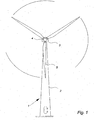
- Fig. 1 illustrates a wind turbine 1, comprising a tower 2 and a wind turbine nacelle 3 positioned on top of the tower 2.
- the wind turbine rotor 4 comprising two wind turbine blades 5, is connected to the nacelle 3 through the low speed shaft 6 which extends out of the nacelle 3 front.
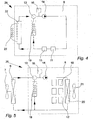
- Fig. 2 illustrates an embodiment of a traditional temperature control system 26 for controlling the temperature of heat generating and/or passive components 8 in a wind turbine 1.
- the illustrated heat generating and/or passive component 8 could be a power converter 9 comprising different kind of power handling equipment 10 such as power resistors 11, motherboards 12 and other.
- the motherboards 12 is air cooled
- the power resistors 11 is both air and fluid cooled.
- a main radiator 6 with a fan 7 is mounted outside the power converter 9 properly in a location enabling free air inlet from the outside of the wind turbine 1.
- a refrigerant flows through a bidirectional valve 13 and through a pump 14 which creates the flow of the refrigerant.
- the pump 14 the refrigerant flows through the equipment 11 in the power converter 9 which demands fluid cooling. The possibly heated refrigerant then returns to the main radiator 6 to be cooled again.
- the refrigerants temperature is measured by a refrigerant thermometer 16 and this temperature is compared with predefined maximum and minimum reference temperatures in a controller 25. If the refrigerants temperature is above the maximum reference temperature the controller 25 starts the fan 7 on the main radiator 6. When the refrigerants temperature drops below the minimum reference temperature, the controller 25 stops the fan 6 again.
- the power converter 9 also contains equipment 12 which only can or needs to be air cooled.
- the cabinet surrounding the power converter 9 is therefore provided with at least one cabinet fan 15 driven air inlets 18.
- An air thermometer 17 can measure the air temperature and compare it to maximum and minimum reference temperatures in the controller 25. If the air temperature is below the minimum reference temperature the cabinet fan 15 stops. When the air temperature inside the cabinet rise above the maximum reference temperature, the fan 15 starts again.
- the wind turbine 1 If the wind turbine 1 is placed in a cold environment and the weather is calm making the power production, and thereby most of the internal heat emission, stop, it can be necessary to heat the power handling equipment 10 in the power converter 9. This can be done by activating the bidirectional valve 13 changing the direction of the refrigerant flow and making it circulate inside the power converter 9 and pass a refrigerant heater 19.
- the equipment in the wind turbine 1 could produce so much heat, that the temperature rises above a certain level which makes some of the equipment shut down to protect them from being damaged by the high temperature. This will make most or the entire power production stop, and thereby also stop most of the internal heat production.
- Fig. 3 illustrates an embodiment of a temperature control system 26 for heat generating and/or passive components 8 in a wind turbine 1 according to the invention.
- the illustrated heat generating and/or passive component 8 could, as also illustrated in fig. 2 , be a power converter 9 comprising different kind of power handling equipment 10. Some of the equipment 10 is air cooled, and some is both air and fluid cooled.
- a main radiator 6 with a fan 7 is mounted outside the power converter 9 ensuring proper heat-exchange with the surroundings.
- the refrigerant flows through a bidirectional valve 13 and through a pump 14 which creates the flow of the refrigerant.
- the pump 14 the refrigerant flows through an internal radiator 20 provided with an internal fan 21.
- the radiator 20 and the fan 21 blows cooled air on and past the components that needs air cooling such as the motherboards 12 or it ensures a flow of air inside the cabinet.
- the refrigerant flows through the equipment 11 in the power converter 9 which demands fluid cooling.
- the possibly heated refrigerant then returns to the main radiator 6 to be cooled again.
- the temperature control system 26 is provided with a controller 25 which attempts to keep the system temperature on a constant level by maintaining the temperature of the refrigerant constant. This is mainly done by starting and stopping the main radiator fan 7, but it could also be done varying the rotation speed of the fan 7, by varying the speed of the pump 14 or even by starting and stopping the pump 14.
- the temperature can off course not be kept absolutely constant because of the systems inertia, but the fluctuation of the temperature can be kept as little as possible, such as +/- 0,3° C.
- the controller 25 After a preset time, such as 6 hours, the controller 25 lowers the system temperature by e.g. 1° C, or the controller 25 could lower the temperature e.g. 1° C over e.g. 6 hours making the temperature drop linearly. This gradual lowering of the temperature is continued until one of two things happens. The most common scenario is that the temperature is lowered until the systems heat output exceeds the temperature control systems 26 cooling capacity, making the refrigerant and thereby the component 8 temperature rise and reach a new peak level, from where the temperature is gradually lowered again. This relatively slow lowering of the temperature will then continue until the heat output exceeds the temperature control systems cooling capacity again, which creates a new temperature peak and a new controlled lowering starts.
- the controller could gradually lower the temperature until a preset lowest operating temperature, e.g. 0° C, is reached. The temperature would then be maintained constant on this level until the first scenario happens.
- the air temperature in the cabinet could be controlled in the same way as in traditional temperature control systems 26, as explained under fig. 2 , but in this embodiment of the invention, the power converter 9 is provided with an internal radiator 20 and fan 21 which functions as means for controlling the temperature of the equipment 12 in the power converter 9 which only can or needs to be air cooled.
- the air temperature is controlled by the same refrigerant that are used for fluid cooling of some of the equipment 12 in the power converter 9, which makes the temperature difference between the refrigerant and the air surrounding the equipment 12 small and relatively constant.
- the system can keep the equipment on a lowest operating temperature by heating the power handling equipment 10 in the power converter 9. Like in traditional systems this can be done by activating the bidirectional valve 13 changing the direction of the refrigerant flow and making it circulate inside the power converter 9 and passes a refrigerant heater 19.
- the order of the components in the system is not in any way limited to the illustrated order.
- the components of the temperature control system could be placed differently e.g. the refrigerant thermometer 16, the pump 14 and other could be placed after the refrigerant cooled equipment.
- the number of the different component can vary within the scoop of the invention, and some of the components such as pumps 14, refrigerant heaters 19, bidirectional valves 13 and other could be placed outside the power converter 9 or the other heat generating and/or passive components 8 of the wind turbine 1, in which the temperature control system according to the invention is applied.
- Different heat generating and/or passive components 8 of the wind turbine 1 could also share different components of the temperature control system e.g. one main radiator 6 could be attached to different or the same temperature control systems 26 in different heat generating and/or passive components 8 or a single controller 25 could control all the temperature control systems 26 in or at the wind turbine 1.
- Fig. 4 illustrates an embodiment of a temperature control system 26 for e.g. a gear, a hydraulic system or other heat generating and/or passive components 8 of a wind turbine 1.
- the heat generating and/or passive component 8 is equipped with an active cooling device 22 comprising a compressor.
- the active cooling device 8 could be of the type generally known from refrigerators and freezers.
- the cooling pipes 23 of the active cooling device 22 are placed outside the heat generating and/or passive component 8 and possibly even outside the wind turbine 1.
- the heat generating and/or passive component 8 contains no equipment that needs air cooling.
- the refrigerant flows from the active cooling device 22 through a bidirectional valve 13, a pump 12 and through the parts of the heat generating and/or passive component that need cooling or heating. If the refrigerant flows through e.g. the oil sump of a gear or a hydraulic system the thermometer 16 could be placed on the respective oil flow system making the system 26 control the temperature based on the gears or the hydraulic systems oil temperature.
- the previously described refrigerant could be the oil of e.g. a gear or a hydraulic system.
- the heated or cooled refrigerant returns to the active cooling device 22 or to the refrigerant heater 19.
- the temperature control system 26 is controlled by a controller 25 which is not shown in this figure.
- Fig. 5 illustrates an embodiment of the invention where only air cooling is needed.
- the heat generating and/or passive component could in this embodiment be a cabinet comprising controllers or other power handling equipment.
- the refrigerant flows through an internal radiator 20 which cools or heats the air.
- a controller (not shown) could start and stop both the main fan 7 and the internal fan 21 or it could vary the speed of the fans or the pump 14.
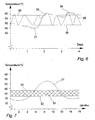
- Fig. 6 illustrates an embodiment of a heat generating and/or passive components 8 temperature curve 28 in a traditional temperature control system 26, and temperature curve 28 in a system according to the invention as seen over four days.
- the solid curve 27 illustrates, that from the start of day one the temperature of the heat generating and/or passive component 8 (as seen on the vertical axis) is lowered 1° C each six hours. This gradual lowering of the temperature goes on for one and a half day, until the ambient temperature and the internal heat production get so high that it exceeds the capacity of the cooling system. This makes the temperature of the heat generating and/or passive component rise until it reaches a peak 24 from where the temperature again is lowered 1 ° C each six hours. This lowering then continues for about a day when a new peak 24 occurs which starts a new gradual lowering of the temperature.
- the curve shown in dotted line 28 illustrates a possible temperature curve 28 for a heat generating and/or passive component 8 in a traditional temperature control system 26. Most often in traditional temperature control systems 26 the temperature will rise until an upper temperature level 29 is reached. This triggers a cooling process, which makes the temperature of the heat generating and/or passive component 8 drop, until a lower temperature level 30 is reached, where the cooling process stops, and the temperature of the heat generating and/or passive component 8 starts to rise again.
- the curves 27, 28 also indicates that the number of temperature fluctuations in a traditional temperature control system 26 is far greater, that in a system 26 according to the invention.
- a controller 25 in a temperature control system 26 could be preset in a controller 25 in a temperature control system 26 according to the invention. It could be as values (e.g. 2° C every 10 hours) or it could be as a predefined reference curve allowing for more complex lowering of the temperature (e.g. linearly or faster just after a peak 24 and then gradually slower or other). In another embodiment of the invention this controller 25 could operate with different temperature steps or different intervals for different times of the day, different times of the year, different ambient temperatures or other.
- N use N test ⁇ ⁇ T test ⁇ ⁇ T use m
- ⁇ Ttest and ⁇ Tuse are the peak-to-peak temperature excursions of the heat generating and/or passive components 8 or component parts in the laboratory and in use in the field, respectively; and Ntest and Nuse are the corresponding number of cycles to failure in the laboratory and in use in an operating wind turbine 1.
- m is a constant, typical value for a given failure mechanism or it is derived from empirical data. E.g. the m value for solder is approximately 2.
- the Coffin-Manson model can be used to define the minimum acceptable number of cycles to failure in an accelerated qualification test.
- Fig. 7 illustrates an embodiment of a heat generating and/or passive components 8 temperature curve 27 as seen over sixteen months. As the solid curve illustrates, the temperature of the heat generating and/or passive components 8 follows the general seasonal changes in the temperature. The curve 27 further illustrates that the average temperature of a heat generating and/or passive component 8 varies over time making it follow the ambient temperature and the wind load on the wind turbine 1.
- the hatched area 31 substantially illustrates the area 31 wherein the component 8 temperature in a traditional temperature control system 26 fluctuates. This fluctuation area 31 is limited by an upper temperature level 29 and a lower temperature level 30.
Description
- The invention relates to a method for prolonging and/or controlling the life of one or more heat generating and/or passive components in a wind turbine, a wind turbine, and use hereof.
- A wind turbine known in the art comprises a wind turbine tower and a wind turbine nacelle positioned on top of the tower. A wind turbine rotor with three wind turbine blades is connected to the nacelle through a low speed shaft, which extends out of the nacelle front as illustrated on
figure 1 . - Thermal stress to components containing or comprising materials of different temperature expand coefficients is a well know problem, and within the art of making wind turbines this problem is particularly pronounced.
- Thermal stress basically originates from two factors - High temperature and more importantly varying temperatures. Examples for controlling thermal stress are disclosed in
WO 2004/085816 orUS 6,212,871 . - Arrhenius' exponential "law", which is a well proven theory, suggest that the higher the temperature, the faster a given chemical reaction will proceed and e.g. regarding electrical components, a rule of thumb says that for every 10° C the temperature is raised, the risk of failures doubles. So to ensure long life of the wind turbines heat generating and/or passive components such as power converters, generators, control systems, gears and hydraulic systems it is known to provide these components with some sort of temperature control, often in form of cooling systems keeping the components operating temperature below a certain level.
- The problem with this solution is, that the ambient temperature varies a lot from site to site, from day to night and from season to season. This combined with the variation in internal heat production, due to varying wind conditions and thereby varying power production, makes the components temperature vary a lot both during the day and night and during the year. Furthermore it is very difficult to estimate the life of the components if there is no or very little control with the size and number of temperature fluctuations.
- Varying temperatures in heat generating and/or passive components is a big problem, mainly because of the fact that different materials have different coefficients of thermal expansion, but also because e.g. lubricants and interacting mechanical components are made to work optimally at a specific temperature.
- The solution to this problem would be to maintain the components temperature fixed at all times. But this would demand a cooling and heating system with a very high capacity, which would be expensive in both manufacturing, operating and maintenance costs. Furthermore such a system or systems would be both big and heavy which is particularly disadvantageous in the art of making wind turbines.
- An object of the invention is therefore to provide a temperature control system for heat generating and/or passive, components in or at a wind turbine without the mentioned disadvantages.
- Furthermore it is an object of the invention to provide for a cost efficient temperature control system that reduces the thermal stress in the heat generating and/or passive components of a wind turbine.
- Especially it is an object of the invention to provide for a cost efficient temperature control system that controls the thermal stress in the heat generating and/or passive components of a wind turbine.
- The invention provides for a method for prolonging and/or controlling the life of one or more heat generating and/or passive components in a wind turbine, with the features of
claim 1. - If the wind turbine was equipped with a temperature control system with a cooling capacity, making it able to control the temperature of the heat generating and/or passive components when their temperature rises, the temperature of the components would not be rising in the first place. But such a temperature control system would be big, heavy and expensive. However when the cooling capacity exceeds the overall heat output, the temperature of the components will start to drop and this process can be controlled by a wind turbine temperature control system of the same size and capacity as an ordinary temperature control system. Even though this control of the components temperature most often will maintain the components temperature at level higher that necessary during the cooling down process (which potentially reduces the components life), it is still advantageous in that, the number of temperature fluctuations is reduced in a way which most often will prolong the total life of the heat generating and/or passive components. And possibly more important, this makes it possible, within a reasonable margin of error, to predict the number of fluctuations and thereby predict the life of the heat generating and/or passive components. This is advantageous in that, it makes it profitable or at least more profitable to replace certain components at certain intervals e.g. in connection with ordinary maintenance of the wind turbine.
- It should be emphasised that by the term "heat generating ... components" is to be understood components, which produce heat e.g. because they conduct electrical power, because they are in motion or other. This could e.g. be an electrically active motherboard, an entire electrically active power converter or a rotating bearing. By the term "... passive components" is to be understood components which does not produce heat themselves, but they could still be under the influence of e.g. the radiation of heat from neighbouring heat generating components and the ambient temperature in general. This could e.g. a motherboard which is turned off; meaning it does not conduct any electrical power, it could be stagnant oil in the oil sump of a gear or a hydraulic system or another component which temporarily or permanently does not generate heat.
- Further, it should be emphasised that the heat generating and/or passive components not necessarily have to be located inside the wind turbine e.g. in the tower or in the nacelle. They could also be located in a cabinet, a shed or a house outside the wind turbine.
- An aspect of the invention provides for a method which comprises the steps of, monitoring the temperature of said one or more of said heat generating and/or passive components, detecting peaks in said one or more heat generating and/or passive components temperature, and controlling the temperature of said one or more heat generating and/or passive components by means of one or more temperature control systems including heating and cooling means, in relation to the latest temperature peak.
- It is advantageous to control the temperature of the heat generating and/or passive components based on the latest temperature peak, in that it ensures efficient use of the temperature control systems, it enables the possibility of controlling the number of temperature fluctuations and at the same time it enables the possibility of reducing the thermal stress on the components.
- It should be emphasised that in this context the term "peak" is to be understood as the point where the temperature shifts from rising to declining.
- An aspect of the invention provides for a method wherein said temperature of said one or more heat generating and/or passive components, is controlled according to a predefined reference curve.
- By lowering the temperature of the heat generating and/or passive components according to a predefined reference curve it is possible lower the temperature in many different more or less complex ways. This is advantageous in that different kinds of wind turbines placed in different environments might need different lowering curves of the temperature e.g. very fast in the beginning and gradually slower or other. This would be useful in attempting to control and reduce the thermal stress in the heat generating and/or passive components.
- Furthermore it is advantageous to control the components temperature according to a predefined reference curve, in that it enables the possibility of controlling the life of the components. The components life is among other things depending on the number of temperature fluctuations it is exposed to during its life. If e.g. the cooling curve declines fast it will potentially lead to more temperature fluctuations than if it declines slowly, whereby shortening the components life.
- An aspect of the invention provides for a method wherein said temperature of said one or more heat generating and/or passive components (8), is controlled according to a linear or substantially linear reference curve.
- It is advantageous to lower the temperature according to a linear reference curve in that it provides for relatively little thermal stress on the heat generating and/or passive components.
- An aspect of the invention provides for a method wherein said temperature of said one or more heat generating and/or passive components, is controlled by lowering said temperature of said one or more of said heat generating and/or passive components in steps.
- It is advantageous to lower the temperature of the heat generating and/or passive components in steps in that it provides for a relatively simple feedback control of the temperature.
- An aspect of the invention provides for a method wherein said temperature of said one or more heat generating and/or passive components, is controlled by lowering said temperature of said one or more heat generating and/or passive components until a predefined lowest operational temperature is reached.
- It is advantageous to lower the temperature of the heat generating and/or passive components until a predefined lowest operational temperature is reached in that, the lower the operational temperature is, the lower the thermal stress is, but only to a certain level where the components could be damaged by to low temperatures e.g. because of rising viscosity of lubricants, shrinkage of mechanically interacting parts and so on.
- An aspect of the invention provides for a method wherein said temperature of said one or more heat generating and/or passive components, is controlled by lowering said temperature until said temperature rises and a new temperature peak occurs.
- It is advantageous to lower the temperature of the heat generating and/or passive components until the temperature rises again and a new temperature peak occurs in that, it provides for a relatively simple closed loop control of the heat generating and/or passive components. Furthermore it is advantageous use of the temperature control system to lower the temperature until the heat produced by the heat generating and/or passive components exceeds the systems cooling capacity and at the same time reducing the thermal stress on the heat generating and/or passive components.
- An aspect of the invention provides for a method wherein said temperature of said one or more heat generating and/or passive components, is controlled by lowering said temperature of said one or more heat generating and/or passive components averagely 1° C between every 10 minutes to 1440 minutes, preferably 60 minutes to 720 minutes and most preferred 180 minutes to 540 minutes.
- The present ranges provides for an advantageous relation between the thermal stress produced by high temperatures and varying temperatures.
- An aspect of the invention provides for a method wherein said temperature of said one or more heat generating and/or passive components, is controlled by controlling the temperature of the air in and/or surrounding one or more of said heat generating and/or passive components and/or controlling the temperature of a fluid mean for internal temperature control of one or more of said heat generating and/or passive components.
- It is advantageous to control the temperature of the air surrounding the components or the air inside the components, in that it is a simple and cost efficient way of controlling the temperature of some heat generating and/or passive components. But air does not have a very high thermal conductivity, so if a component such as a power resistor produces much heat, it is advantageous to establish a refrigerant flow through or around the component.
- An aspect of the invention provides for a method wherein said temperature of said one or more heat generating and/or passive components, is controlled by means at least one refrigerant such as substantially frost-proof water, brine, ammoniac, CO2 and/or Freon gases.
- Using a refrigerant is a simple, cost efficient and well proven way of transporting heat in a temperature control system.
- An aspect of the invention provides for a method wherein said heating and cooling means comprise means for heating or cooling said refrigerant.
- Heating or cooling the refrigerant by means of the heating and cooling means is at simple and well proven way of controlling the temperature in a temperature control system.
- An aspect of the invention provides for a method wherein said heat generating and/or passive components are power handling equipment and/or mechanical components such as power converters, generators, switches, inverters, resistors, hydraulic systems, gears, transformers and control systems.
- It is advantageous to reduce and control the thermal stress on the power handling equipment and/or mechanical components, in that they are essential components of the wind turbine, which can be very expensive and/or difficult to exchange, and it can be very difficult to estimate their life, if the thermal stress is not controlled.
- An aspect of the invention provides for a method wherein said method further include the step of lowering said temperature of said one or more of said heat generating and/or passive components controlled from said peak temperature.
- It is advantageous to lower the temperature of said one or more heat generating and/or passive components controlled, in that it enables the possibility of controlling the size and the number of temperature fluctuations in the heat generating and/or passive components. This is advantageous, in that it enables the possibility of predicting the life of the heat generating and/or passive components within a narrow margin of error.
- An aspect of the invention provides for a method wherein said method further includes the step of positioning said means for controlling the temperature of the air in and/or surrounding one or more of said heat generating and/or passive components inside said heat generating and/or passive components.
- It is advantageous to place the means for controlling the temperature of the air in and/or surrounding the heat generating and/or passive components inside the heat generating and/or passive components, in that it enables the possibility of cooling/heating the air by circulating the air inside the component through the means for controlling the temperature of the air. Hereby air-exchange with the surroundings can be avoided, which is advantageous, in that the outside air can have varying humidity, it can contain bugs or other things potentially harmful for the component.
- An aspect of the invention provides for a method wherein said method further includes the step of controlling the temperature of said means for controlling the temperature, of the air in and/or surrounding one or more of said heat generating and/or passive components, by means of said refrigerant.
- Using the refrigerant to control the temperature of the air in or around the components is advantageous, in that it enables the possibility of using the same refrigerant to control the temperature of the air and to flow through the fluid cooled/heated components. This is advantageous in that it ensures a relatively low and constant temperature difference between the air surrounding a component and the refrigerant flowing through the component, hereby reducing the thermal stress on the component.
- An aspect of the invention provides for a method wherein said temperature of said one or more heat generating and/or passive components, is controlled by varying the output of said heating and cooling means.
- It is advantageous to control the temperature of the heat generating and/or passive components by varying the output of the heating and cooling means of the temperature control system in that, it is a relatively simple way of controlling the temperatures.
- An aspect of the invention provides for a method wherein said temperature of said one or more heat generating and/or passive components, is controlled by turning said heating and cooling means on and off.
- It is advantageous to control the temperature of the heat generating and/or passive components by turning said heating and cooling means on and off, in that it is a simple and cost efficient way of controlling the temperature.
- The invention further provides for a wind turbine comprising the features of
claim 19. - Controlling the cooling down procedure of the heat generating and/or passive components in a wind turbine is advantageous, in that it enables the possibility of reducing the number of temperature fluctuations and calculating, predicting or estimating the number of temperature fluctuations rather accurately, whereby making it possible to prolong and control the life of the heat generating and/or passive components in a wind turbine.
- An aspect of the invention provides for a wind turbine, wherein said means comprise, one or more temperature control systems including heating and cooling means, means for monitoring the temperature of one or more of said heat generating and/or passive components, means for detecting peaks in said one or more heat generating and/or passive components temperature, and means for controlling the temperature of said one or more heat generating and/or passive components by means of said one or more temperature control systems in relation to the latest temperature peak.
- It is advantageous to control the temperature of the heat generating and/or passive components of a wind turbine in relation to the latest temperature peak in that it enables the possibility controlling the temperature of the heat generating and/or passive components in a way that reduces the thermal stress on the components.
- An aspect of the invention provides for a wind turbine, wherein said means lowers the temperature of said one or more heat generating and/or passive components, according to a predefined reference curve.
- An aspect of the invention provides for a wind turbine, wherein said predefined reference curve provides for substantially linearly lowering of said temperature.
- An aspect of the invention provides for a wind turbine, wherein said predefined reference curve provides for lowering of said temperature in steps.
- An aspect of the invention provides for a wind turbine, wherein said means lowers the temperature of said one or more heat generating and/or passive components until a predefined lowest operational temperature is reached or until said temperature rises and a new temperature peak occurs.
- An aspect of the invention provides for a wind turbine, wherein said means lowers the temperature of said one or more heat generating and/or passive components averagely 1° C between every 10 minutes to 1440 minutes, preferably 60 minutes to 720 minutes and most preferred 180 minutes to 540 minutes.
- An aspect of the invention provides for a wind turbine, wherein said means further comprise at least one refrigerant such as substantially frost-proof water, brine, ammoniac, CO2 and/or Freon gases.
- An aspect of the invention provides for a wind turbine, wherein said heating and cooling means comprise means for heating or cooling said refrigerant.
- An aspect of the invention provides for a wind turbine, wherein said heat generating and/or passive components are power handling equipment and/or mechanical components such as power converters, generators, switches, inverters, resistors, hydraulic systems, gears, transformers and control systems.
- An aspect of the invention provides for a wind turbine, wherein said means lowers the temperature of said one or more heat generating and/or passive components controlled from said peak temperature.
- An aspect of the invention provides for a wind turbine, wherein means controls the temperature of said one or more heat generating and/or passive components by varying the output of said heating and cooling means.
- An aspect of the invention provides for a wind turbine, wherein said means controls the temperature of said one or more heat generating and/or passive components by turning said heating and cooling means on and off.
- An aspect of the invention provides for a wind turbine, wherein said means comprise means for controlling the temperature of the air in and/or surrounding one or more of said heat generating and/or passive components and/or fluid means for internal temperature control of one or more of said heat generating and/or passive components.
- An aspect of the invention provides for a wind turbine, wherein said means for controlling the temperature of the air in and/or surrounding one or more of said heat generating and/or passive components are positioned inside said heat generating and/or passive components.
- An aspect of the invention provides for a wind turbine, wherein said means controls the temperature of said means for controlling the temperature, of the air in and/or surrounding one or more of said heat generating and/or passive components, by means of said refrigerant.
- The invention further provides for a wind turbine according to any of
claims 20 to 35, wherein said wind turbine is a variable speed pitch controlled wind turbine. - Even further the invention provides for use of wind turbine according to any of
claims 19 to 35 in combination with a method according to any ofclaims 1 to 18. - The invention will be described in the following with reference to the figures in which
- fig. 1.
- illustrates a large wind turbine as seen from the front,
- fig. 2
- illustrates an embodiment of a traditional temperature control system for heat generating and/or passive components in a wind turbine,
- fig. 3
- illustrates an embodiment of a temperature control system for heat generating and/or passive components in a wind turbine according to the invention,
- fig. 4
- illustrates another embodiment of a temperature control system for heat generating and/or passive components in a wind turbine according to the invention,
- fig. 5
- illustrates third embodiment of a temperature control system for heat generating and/or passive components in a wind turbine according to the invention,
- fig. 6
- illustrates an embodiment of two curves illustrating a heat generating and/or passive components temperature as seen over four days, and
- fig. 7
- illustrates an embodiment of heat generating and/or passive components temperature curves as seen over sixteen months.
-
Fig. 1 illustrates awind turbine 1, comprising atower 2 and awind turbine nacelle 3 positioned on top of thetower 2. Thewind turbine rotor 4, comprising twowind turbine blades 5, is connected to thenacelle 3 through thelow speed shaft 6 which extends out of thenacelle 3 front. -
Fig. 2 illustrates an embodiment of a traditionaltemperature control system 26 for controlling the temperature of heat generating and/orpassive components 8 in awind turbine 1. - In this embodiment the illustrated heat generating and/or
passive component 8 could be a power converter 9 comprising different kind ofpower handling equipment 10 such aspower resistors 11,motherboards 12 and other. In this embodiment themotherboards 12 is air cooled, and thepower resistors 11 is both air and fluid cooled. - A
main radiator 6 with afan 7 is mounted outside the power converter 9 properly in a location enabling free air inlet from the outside of thewind turbine 1. From the main radiator 6 a refrigerant flows through abidirectional valve 13 and through apump 14 which creates the flow of the refrigerant. From thepump 14 the refrigerant flows through theequipment 11 in the power converter 9 which demands fluid cooling. The possibly heated refrigerant then returns to themain radiator 6 to be cooled again. - On the way out of the power converter 9 the refrigerants temperature is measured by a
refrigerant thermometer 16 and this temperature is compared with predefined maximum and minimum reference temperatures in acontroller 25. If the refrigerants temperature is above the maximum reference temperature thecontroller 25 starts thefan 7 on themain radiator 6. When the refrigerants temperature drops below the minimum reference temperature, thecontroller 25 stops thefan 6 again. - The power converter 9 also contains
equipment 12 which only can or needs to be air cooled. The cabinet surrounding the power converter 9 is therefore provided with at least onecabinet fan 15 drivenair inlets 18. Anair thermometer 17 can measure the air temperature and compare it to maximum and minimum reference temperatures in thecontroller 25. If the air temperature is below the minimum reference temperature thecabinet fan 15 stops. When the air temperature inside the cabinet rise above the maximum reference temperature, thefan 15 starts again. - If the
wind turbine 1 is placed in a cold environment and the weather is calm making the power production, and thereby most of the internal heat emission, stop, it can be necessary to heat thepower handling equipment 10 in the power converter 9. This can be done by activating thebidirectional valve 13 changing the direction of the refrigerant flow and making it circulate inside the power converter 9 and pass arefrigerant heater 19. - If the ambient temperature is high and the weather is windy, the equipment in the
wind turbine 1 could produce so much heat, that the temperature rises above a certain level which makes some of the equipment shut down to protect them from being damaged by the high temperature. This will make most or the entire power production stop, and thereby also stop most of the internal heat production. -
Fig. 3 illustrates an embodiment of atemperature control system 26 for heat generating and/orpassive components 8 in awind turbine 1 according to the invention. - In this embodiment the illustrated heat generating and/or
passive component 8 could, as also illustrated infig. 2 , be a power converter 9 comprising different kind ofpower handling equipment 10. Some of theequipment 10 is air cooled, and some is both air and fluid cooled. - Like in the traditional systems a
main radiator 6 with afan 7 is mounted outside the power converter 9 ensuring proper heat-exchange with the surroundings. From themain radiator 6 the refrigerant flows through abidirectional valve 13 and through apump 14 which creates the flow of the refrigerant. From thepump 14 the refrigerant flows through aninternal radiator 20 provided with aninternal fan 21. Theradiator 20 and thefan 21 blows cooled air on and past the components that needs air cooling such as themotherboards 12 or it ensures a flow of air inside the cabinet. - From the
radiator 20 the refrigerant flows through theequipment 11 in the power converter 9 which demands fluid cooling. The possibly heated refrigerant then returns to themain radiator 6 to be cooled again. - Somewhere inside the power converter 9, properly between the
bidirectional valve 13 and thepump 14 the temperature of the refrigerants is measured by arefrigerant thermometer 16. Thetemperature control system 26 is provided with acontroller 25 which attempts to keep the system temperature on a constant level by maintaining the temperature of the refrigerant constant. This is mainly done by starting and stopping themain radiator fan 7, but it could also be done varying the rotation speed of thefan 7, by varying the speed of thepump 14 or even by starting and stopping thepump 14. The temperature can off course not be kept absolutely constant because of the systems inertia, but the fluctuation of the temperature can be kept as little as possible, such as +/- 0,3° C. - After a preset time, such as 6 hours, the
controller 25 lowers the system temperature by e.g. 1° C, or thecontroller 25 could lower the temperature e.g. 1° C over e.g. 6 hours making the temperature drop linearly. This gradual lowering of the temperature is continued until one of two things happens. The most common scenario is that the temperature is lowered until the systems heat output exceeds thetemperature control systems 26 cooling capacity, making the refrigerant and thereby thecomponent 8 temperature rise and reach a new peak level, from where the temperature is gradually lowered again. This relatively slow lowering of the temperature will then continue until the heat output exceeds the temperature control systems cooling capacity again, which creates a new temperature peak and a new controlled lowering starts. - If the wind turbine is sited in a cold environment and the weather is calm making the power production stop, the controller could gradually lower the temperature until a preset lowest operating temperature, e.g. 0° C, is reached. The temperature would then be maintained constant on this level until the first scenario happens.
- According to the invention the air temperature in the cabinet could be controlled in the same way as in traditional
temperature control systems 26, as explained underfig. 2 , but in this embodiment of the invention, the power converter 9 is provided with aninternal radiator 20 andfan 21 which functions as means for controlling the temperature of theequipment 12 in the power converter 9 which only can or needs to be air cooled. This means that the air temperature is controlled by the same refrigerant that are used for fluid cooling of some of theequipment 12 in the power converter 9, which makes the temperature difference between the refrigerant and the air surrounding theequipment 12 small and relatively constant. - If the
wind turbine 1 is placed in a cold environment and the weather temporarily is calm, the system can keep the equipment on a lowest operating temperature by heating thepower handling equipment 10 in the power converter 9. Like in traditional systems this can be done by activating thebidirectional valve 13 changing the direction of the refrigerant flow and making it circulate inside the power converter 9 and passes arefrigerant heater 19. - It should be understood, that the order of the components in the system is not in any way limited to the illustrated order. In another embodiment of the invention the components of the temperature control system could be placed differently e.g. the
refrigerant thermometer 16, thepump 14 and other could be placed after the refrigerant cooled equipment. Likewise, the number of the different component can vary within the scoop of the invention, and some of the components such aspumps 14,refrigerant heaters 19,bidirectional valves 13 and other could be placed outside the power converter 9 or the other heat generating and/orpassive components 8 of thewind turbine 1, in which the temperature control system according to the invention is applied. Different heat generating and/orpassive components 8 of thewind turbine 1 could also share different components of the temperature control system e.g. onemain radiator 6 could be attached to different or the sametemperature control systems 26 in different heat generating and/orpassive components 8 or asingle controller 25 could control all thetemperature control systems 26 in or at thewind turbine 1. -
Fig. 4 illustrates an embodiment of atemperature control system 26 for e.g. a gear, a hydraulic system or other heat generating and/orpassive components 8 of awind turbine 1. - In this embodiment of the invention the heat generating and/or
passive component 8 is equipped with anactive cooling device 22 comprising a compressor. Theactive cooling device 8 could be of the type generally known from refrigerators and freezers. The coolingpipes 23 of theactive cooling device 22 are placed outside the heat generating and/orpassive component 8 and possibly even outside thewind turbine 1. - In this embodiment of the invention the heat generating and/or
passive component 8 contains no equipment that needs air cooling. The refrigerant flows from theactive cooling device 22 through abidirectional valve 13, apump 12 and through the parts of the heat generating and/or passive component that need cooling or heating. If the refrigerant flows through e.g. the oil sump of a gear or a hydraulic system thethermometer 16 could be placed on the respective oil flow system making thesystem 26 control the temperature based on the gears or the hydraulic systems oil temperature. In another embodiment of the invention the previously described refrigerant could be the oil of e.g. a gear or a hydraulic system. - From the equipment to which the refrigerant flows, the heated or cooled refrigerant returns to the
active cooling device 22 or to therefrigerant heater 19. - The
temperature control system 26 is controlled by acontroller 25 which is not shown in this figure. -
Fig. 5 illustrates an embodiment of the invention where only air cooling is needed. The heat generating and/or passive component could in this embodiment be a cabinet comprising controllers or other power handling equipment. - The refrigerant flows through an
internal radiator 20 which cools or heats the air. To control the air temperature, a controller (not shown) could start and stop both themain fan 7 and theinternal fan 21 or it could vary the speed of the fans or thepump 14. -
Fig. 6 illustrates an embodiment of a heat generating and/orpassive components 8temperature curve 28 in a traditionaltemperature control system 26, andtemperature curve 28 in a system according to the invention as seen over four days. - The
solid curve 27 illustrates, that from the start of day one the temperature of the heat generating and/or passive component 8 (as seen on the vertical axis) is lowered 1° C each six hours. This gradual lowering of the temperature goes on for one and a half day, until the ambient temperature and the internal heat production get so high that it exceeds the capacity of the cooling system. This makes the temperature of the heat generating and/or passive component rise until it reaches a peak 24 from where the temperature again is lowered 1 ° C each six hours. This lowering then continues for about a day when anew peak 24 occurs which starts a new gradual lowering of the temperature. - The curve shown in dotted
line 28 illustrates apossible temperature curve 28 for a heat generating and/orpassive component 8 in a traditionaltemperature control system 26. Most often in traditionaltemperature control systems 26 the temperature will rise until anupper temperature level 29 is reached. This triggers a cooling process, which makes the temperature of the heat generating and/orpassive component 8 drop, until alower temperature level 30 is reached, where the cooling process stops, and the temperature of the heat generating and/orpassive component 8 starts to rise again. - The
curves temperature control system 26 is far greater, that in asystem 26 according to the invention. - How often the temperature is lowered and how much it is lowered each time, could be preset in a
controller 25 in atemperature control system 26 according to the invention. It could be as values (e.g. 2° C every 10 hours) or it could be as a predefined reference curve allowing for more complex lowering of the temperature (e.g. linearly or faster just after apeak 24 and then gradually slower or other). In another embodiment of the invention thiscontroller 25 could operate with different temperature steps or different intervals for different times of the day, different times of the year, different ambient temperatures or other. - By lowering the temperature bit by bit in fixed intervals it is possible to estimate the heat generating and/or
passive components 8 or the different parts in the heat generating and/or passive component durability or life. - One way of doing this, is by use of the Coffin-Manson model, which was developed to predict low cycle fatigue failures in metals. The model allows the number of cycles to failure in accelerated laboratory tests to be correlated with the heat generating and/or
passive components 8 in use in awind turbine 1, so that the expected time to failure of the heat generating and/orpassive components 8 or the parts of which they consists can be estimated. - The Coffin-Manson model is as follows:

- Where ΔTtest and ΔTuse are the peak-to-peak temperature excursions of the heat generating and/or
passive components 8 or component parts in the laboratory and in use in the field, respectively; and Ntest and Nuse are the corresponding number of cycles to failure in the laboratory and in use in anoperating wind turbine 1. - m is a constant, typical value for a given failure mechanism or it is derived from empirical data. E.g. the m value for solder is approximately 2.
- If the peak-to-peak temperature excursion and cyclic frequency associated with a heat generating and/or passive component is known, and there is a target reliability during the service life, the Coffin-Manson model can be used to define the minimum acceptable number of cycles to failure in an accelerated qualification test.
- This means that if ΔTuse, Ntest and Nuse is known, it is possible, within a reasonable margin of error, to predict the life of the heat generating and/or
passive components 8 or the parts in the heat generating and/or passive components, making it possible and economically advantageous to exchange heat generating and/orpassive components 8 or parts of the heat generating and/or passive components as part of the regular service of thewind turbines 1. - An effect of this control of the lowering of the
components 8 temperature and thereby the possibility of estimating the life of thecomponents 8 is, that it is possible to foresee the consequences of a deliberate overproduction. This could e.g. be if awind turbine 1 was used for compensating for peaks in the general power consumption. This could mean that over a period of time, thewind turbine 1 was set to produce more power than it was accentually designed for, making thecomponents 8 temperature rise. This could lead to an overall reduction in some or all of thecomponents 8 life, but due to the controlled cooling down procedure it is still possible to predict thecomponents 8 life, making the system very reliable. -
Fig. 7 illustrates an embodiment of a heat generating and/orpassive components 8temperature curve 27 as seen over sixteen months. As the solid curve illustrates, the temperature of the heat generating and/orpassive components 8 follows the general seasonal changes in the temperature. Thecurve 27 further illustrates that the average temperature of a heat generating and/orpassive component 8 varies over time making it follow the ambient temperature and the wind load on thewind turbine 1. - The hatched area 31 substantially illustrates the area 31 wherein the
component 8 temperature in a traditionaltemperature control system 26 fluctuates. This fluctuation area 31 is limited by anupper temperature level 29 and alower temperature level 30. - The invention has been exemplified above with reference to specific examples of
temperature control systems 26 for heat generating and/orpassive components 8 of awind turbine 1. However, it should be understood that the invention is not limited to the particular examples described above but may be designed and altered in a multitude of varieties within the scope of the invention as specified in the claims. -
- 1.
- Wind turbine
- 2.
- Tower
- 3.
- Nacelle
- 4.
- Rotor
- 5.
- Blade
- 6.
- Main radiator
- 7.
- Main radiator fan
- 8.
- Heat generating and/or passive component
- 9.
- Power converter
- 10.
- Power handling equipment
- 11.
- Power resistor
- 12.
- Motherboard
- 13.
- Bidirectional valve
- 14.
- Pump
- 15.
- Cabinet fan
- 16.
- Refrigerant thermometer
- 17.
- Air thermometer
- 18.
- Air inlet
- 19.
- Refrigerant heater
- 20.
- Internal radiator
- 21.
- Internal fan
- 22.
- Active cooling device
- 23.
- Cooling pipes
- 24.
- Temperature peak
- 25.
- Controller
- 26.
- Temperature control system
- 27.
- Temperature curve in a system according to the invention
- 28.
- Temperature curve in a traditional system
- 29.
- Upper temperature level
- 30.
- Lower temperature level 31. Fluctuation area
Claims (36)
- Method for prolonging and/or controlling the life of one or more heat generating and/or passive components (8) in a wind turbine (1), by controlling the cooling down procedure of said one or more heat generating and/or passive components (8), by gradually lowering the temperature of said one or more heat generating and/or passive components (8) to reduce the number of temperature fluctuations of the heat generating and/or passive components (8).
- Method according to claim 1, said method comprising the steps of
monitoring the temperature of said one or more of said heat generating and/or passive components (8),
detecting peaks (24) in said one or more heat generating and/or passive components (8) temperature, and
controlling the temperature of said one or more heat generating and/or passive components (8) by means of one or more temperature control systems (26) including heating and cooling means (6, 7, 15, 19, 20, 21, 22), in relation to the latest temperature peak (24). - Method according to claim 1 or 2, wherein said temperature of said one or more heat generating and/or passive components (8), is controlled according to a predefined reference curve.
- Method according to any of the preceding claims, wherein said temperature of said one or more heat generating and/or passive components (8), is controlled according to a linear or substantially linear reference curve.
- Method according to any of the preceding claims, wherein said temperature of said one or more heat generating and/or passive components (8), is controlled by lowering said temperature of said one or more of said heat generating and/or passive components (8) in steps.
- Method according to any of the preceding claims, wherein said temperature of said one or more heat generating and/or passive components (8), is controlled by lowering said temperature of said one or more heat generating and/or passive components (8) until a predefined lowest operational temperature is reached.
- Method according to any of the preceding claims, wherein said temperature of said one or more heat generating and/or passive components (8), is controlled by lowering said temperature until said temperature rises and a new temperature peak (24) occurs.
- Method according to any of the preceding claims, wherein said temperature of said one or more heat generating and/or passive components (8), is controlled by lowering said temperature of said one or more heat generating and/or passive components (8) averagely 1° C between every 10 minutes to 1440 minutes, preferably 60 minutes to 720 minutes and most preferred 180 minutes to 540 minutes.
- Method according to any of the preceding claims, wherein said temperature of said one or more heat generating and/or passive components (8), is controlled by controlling the temperature of the air in and/or surrounding one or more of said heat generating and/or passive components (8) and/or controlling the temperature of a fluid mean for internal temperature control of one or more of said heat generating and/or passive components (8).
- Method according to any of the preceding claims, wherein said temperature of said one or more heat generating and/or passive components (8), is controlled by means at least one refrigerant such as substantially frost-proof water, brine, ammoniac, CO2 and/or Freon gases.
- Method according to any of the preceding claims, wherein said heating and cooling means comprise means for heating or cooling said refrigerant.
- Method according to any of the preceding claims, wherein said heat generating and/or passive components (8) are power handling equipment (10) and/or mechanical components such as power converters (9), generators, switches, inverters, resistors (11), hydraulic systems, gears, transformers and control systems.
- Method according to any of claims 2 to 12, wherein said method further include the step of lowering said temperature of said one or more of said heat generating and/or passive components (8) controlled from said peak (24) temperature.
- Method according to any of claims 2 to 13, wherein said method further include the step of positioning said means (20, 21) for controlling the temperature of the air in and/or surrounding one or more of said heat generating and/or passive components (8) inside said heat generating and/or passive components (8).
- Method according any of claims 2 to 14, wherein said method further include the step of controlling the temperature of said means for controlling the temperature (20, 21), of the air in and/or surrounding one or more of said heat generating and/or passive components (8), by means of said refrigerant.
- Method according any of claims 2 to 15, wherein said temperature of said one or more heat generating and/or passive components (8), is controlled by varying the output of said heating and cooling means (6, 7, 15, 19, 20, 21, 22).
- Method according any of claims 2 to 16, wherein said temperature of said one or more heat generating and/or passive components (8), is controlled by turning said heating and cooling means (6, 7, 15, 19, 20, 21, 22) on and off.
- Method according any of the preceding claims, wherein said method further comprises estimating the life of said components (8) by use of one or more fatigue life prediction models such as the Coffin-Manson model.
- A wind turbine (1) comprising means for prolonging and/or controlling the life of one or more heat generating and/or passive components (8), by controlling the
cooling down procedure of said one or more heat generating and/or passive components (8), by gradually lowering the temperature of said one or more heat generating and/or passive components (8) to reduce the number of temperature fluctuations of the heat generating and/or passive components (8). - A wind turbine (1) according to claim 19, wherein said means comprise,
one or more temperature control systems (26) including heating and cooling means (6, 7, 15, 19, 20, 21, 22),
means for monitoring the temperature (16, 17) of one or more of said heat generating and/or passive components (8),
means for detecting peaks (24) in said one or more heat generating and/or passive components (8) temperature, and
means for controlling the temperature of said one or more heat generating and/or passive components (8) by means of said one or more temperature control systems (26) in relation to the latest temperature peak (24). - A wind turbine (1) according to claim 19 or 20, wherein said means lowers the temperature of said one or more heat generating and/or passive components (8), according to a predefined reference curve.
- A wind turbine (1) according to claim 21, wherein said predefined reference curve provides for substantially linearly lowering of said temperature.
- A wind turbine (1) according to claim 21, wherein said predefined reference curve provides for lowering of said temperature in steps.
- A wind turbine (1) according to any of claims 19 to 23 , wherein said means lowers the temperature of said one or more heat generating and/or passive components until a predefined lowest operational temperature is reached or until said temperature rises and a new temperature peak (24) occurs.
- A wind turbine (1) according to any of claims 19 to 24, wherein said means lowers the temperature of said one or more heat generating and/or passive components (8) averagely 1° C between every 10 minutes to 1440 minutes, preferably 60 minutes to 720 minutes and most preferred 180 minutes to 540 minutes.
- A wind turbine (1) according to any of claims 19 to 25, wherein said means further comprise at least one refrigerant such as substantially frost-proof water, brine, ammoniac, CO2 and/or Freon gases.
- A wind turbine (1) according to any of claims 19 to 26, wherein said heating and cooling means comprise means for heating or cooling said refrigerant.
- A wind turbine (1) according to any of claims 19 to 27, wherein said heat generating and/or passive components (8) are power handling equipment (10) and/or mechanical components such as power converters (9), generators, switches, inverters, resistors (11), hydraulic systems, gears, transformers and control systems.
- A wind turbine (1) according to any of claims 20 to 28, wherein said means lowers the temperature of said one or more heat generating and/or passive components (8) controlled from said peak temperature (24).
- A wind turbine (1) according to any of claims 20 to 29, wherein means controls the temperature of said one or more heat generating and/or passive components (8) by varying the output of said heating and cooling means (6, 7, 15, 19, 20, 21, 22).
- A wind turbine (1) according to any of claims 20 to 30, wherein said means controls the temperature of said one or more heat generating and/or passive components (8) by turning said heating and cooling means (6, 7, 15, 19, 20, 21, 22) on and off.
- A wind turbine (1) according to any of claims 20 to 31, wherein said means comprise means for controlling the temperature of the air in and/or surrounding one or more of said heat generating and/or passive components (8) and/or fluid means for internal temperature control of one or more of said heat generating and/or passive components (8).
- A wind turbine (1) according to claim 32, wherein said means for controlling the temperature (20, 21) of the air in and/or surrounding one or more of said heat generating and/or passive components (8) are positioned inside said heat generating and/or passive components (8).
- A wind turbine (1) according to any of claims 20 to 33, wherein said means controls the temperature of said means for controlling the temperature (20,21), of the air in and/or surrounding one or more of said heat generating and/or passive components (8), by means of said refrigerant.
- A wind turbine (1) according to any of claims 19 to 34, wherein said wind turbine (1) is a variable speed pitch controlled wind turbine.
- Use of wind turbine (1) according to any of claims 19 to 34 in combination with a method according to any of claims 1 to 18.
Applications Claiming Priority (1)
| Application Number | Priority Date | Filing Date | Title |
|---|---|---|---|
| PCT/DK2005/000698 WO2007051464A1 (en) | 2005-11-01 | 2005-11-01 | A method for prolonging and/or controlling the life of one or more heat generating and/or passive components in a wind turbine, a wind turbine, and use thereof |
Publications (2)
| Publication Number | Publication Date |
|---|---|
| EP1945944A1 EP1945944A1 (en) | 2008-07-23 |
| EP1945944B1 true EP1945944B1 (en) | 2015-04-15 |
Family
ID=36190693
Family Applications (1)
| Application Number | Title | Priority Date | Filing Date |
|---|---|---|---|
| EP05799113.5A Not-in-force EP1945944B1 (en) | 2005-11-01 | 2005-11-01 | A method for prolonging and/or controlling the life of one or more heat generating and/or passive components in a wind turbine, a wind turbine, and use thereof |
Country Status (8)
| Country | Link |
|---|---|
| US (1) | US7955045B2 (en) |
| EP (1) | EP1945944B1 (en) |
| CN (1) | CN101300420B (en) |
| AU (1) | AU2005337986B2 (en) |
| BR (1) | BRPI0520632A2 (en) |
| CA (1) | CA2627904C (en) |
| ES (1) | ES2536740T3 (en) |
| WO (1) | WO2007051464A1 (en) |
Cited By (1)
| Publication number | Priority date | Publication date | Assignee | Title |
|---|---|---|---|---|
| DE102017120284A1 (en) * | 2017-09-04 | 2019-03-07 | Innogy Se | A method of monitoring the condition of at least one component loaded during operation of a wind turbine |
Families Citing this family (31)
| Publication number | Priority date | Publication date | Assignee | Title |
|---|---|---|---|---|
| WO2008131766A2 (en) * | 2007-04-30 | 2008-11-06 | Vestas Wind Systems A/S | A wind turbine, a method for controlling the temperature of fluid flowing in a first temperature control system of a wind turbine and use |
| JP4796009B2 (en) * | 2007-05-18 | 2011-10-19 | 三菱重工業株式会社 | Wind power generator |
| DE102007045410A1 (en) * | 2007-09-21 | 2009-04-09 | Innovative Windpower Ag | Method for starting a wind energy plant |
| DE102007049599A1 (en) * | 2007-10-15 | 2009-05-07 | Innovative Windpower Ag | Temperature control of coupled gearbox and generator in a wind turbine |
| EP2232697A1 (en) | 2007-12-14 | 2010-09-29 | Vestas Wind Systems A/S | Lifetime optimization of a wind turbine generator by controlling the generator temperature |
| ATE511605T1 (en) * | 2007-12-21 | 2011-06-15 | Vestas Wind Sys As | WIND TURBINE GENERATOR WITH HEAT EXCHANGER |
| EP2208888A3 (en) * | 2008-11-18 | 2012-02-22 | Vestas Wind Systems A/S | A wind turbine with a refrigeration system and a method of providing cooling of a heat generating component in a nacelle for a wind turbine |
| US8504213B2 (en) * | 2009-06-26 | 2013-08-06 | General Electric Company | Regulation of generating plant |
| US9058574B2 (en) * | 2009-07-01 | 2015-06-16 | European Aeronautic Defence And Space Company Eads France | Method for estimating the lifespan of a deep-sub-micron integrated electronic circuit |
| ES2381918T3 (en) | 2009-10-06 | 2012-06-01 | Siemens Aktiengesellschaft | Method to control a wind turbine at high thermal loads |
| EP2507512B1 (en) * | 2009-12-01 | 2016-06-01 | Vestas Wind Systems A/S | A wind turbine nacelle comprising a heat exchanger assembly |
| JP5072994B2 (en) * | 2010-03-17 | 2012-11-14 | 三菱重工業株式会社 | Wind power generator |
| EP2421130A1 (en) * | 2010-08-20 | 2012-02-22 | Siemens Aktiengesellschaft | Method and sensor unit for determining the current usage level indicator value of an electric and/or electronic component in a wind turbine |
| CN103124848B (en) * | 2010-08-31 | 2015-09-16 | 维斯塔斯风力系统有限公司 | There is the wind turbine of heat transfer system |
| DE102010051675A1 (en) * | 2010-11-17 | 2012-05-24 | Repower Systems Ag | Wind energy plant and method for operating a wind turbine with temperature monitoring of the transformer |
| WO2012129721A1 (en) | 2011-03-29 | 2012-10-04 | General Electric Company | Method for adjusting power output of wind turbine |
| EP2520797B1 (en) * | 2011-05-03 | 2015-10-21 | Siemens Aktiengesellschaft | Direct drive wind turbine with a thermal control system |
| US9160172B2 (en) * | 2011-10-12 | 2015-10-13 | General Electric Company | Systems and methods for adaptive possible power determinaton in power generating systems |
| US8624411B2 (en) * | 2011-10-14 | 2014-01-07 | General Electric Company | Power generation system including predictive control apparatus to reduce influences of weather-varying factors |
| JP5308547B2 (en) * | 2012-01-12 | 2013-10-09 | 三菱重工業株式会社 | Fan device for wind turbine generator and wind turbine generator |
| EP2700815B1 (en) | 2012-08-24 | 2016-04-20 | Siemens Aktiengesellschaft | Operating a wind turbine with multiple temperature sensors |
| WO2014114295A1 (en) * | 2013-01-25 | 2014-07-31 | Vestas Wind Systems A/S | Control of wind turbines |
| GB2510824B (en) * | 2013-02-13 | 2016-05-04 | Romax Tech Ltd | Lubricant heating and cooling system for a wind or water turbine |
| US9593670B2 (en) * | 2014-04-30 | 2017-03-14 | General Electric Company | System and methods for reducing wind turbine noise |
| DE102014112458B4 (en) | 2014-08-29 | 2018-10-11 | Sma Solar Technology Ag | Method for controlling a cooling device for increasing the service life of waste heat-generating components and cooling device |
| ES1149337Y (en) * | 2015-12-23 | 2016-04-12 | Zheng Ye | REFRIGERATION DEVICE FOR AEROGENERATING COMPONENTS |
| DE102015122855A1 (en) * | 2015-12-28 | 2017-06-29 | Wobben Properties Gmbh | Wind turbine and cooling device for a wind turbine |
| NL2016384B1 (en) * | 2016-03-08 | 2017-09-27 | Univ Delft Tech | Wind turbine. |
| CN106686956B (en) * | 2017-02-23 | 2019-03-01 | 阳光电源股份有限公司 | Wind energy converter heat dissipating method, radiator and cooling system |
| CN109779835B (en) * | 2017-11-14 | 2020-06-16 | 新疆金风科技股份有限公司 | Power control method and device of wind generating set |
| EP4160009A1 (en) * | 2021-10-01 | 2023-04-05 | Siemens Gamesa Renewable Energy A/S | Method of controlling a wind turbine |
Family Cites Families (8)
| Publication number | Priority date | Publication date | Assignee | Title |
|---|---|---|---|---|
| US5142860A (en) * | 1990-06-18 | 1992-09-01 | United Technologies Corporation | Constant thrust retention turbine temperature limit system |
| DE19624171C1 (en) * | 1996-06-18 | 1998-01-08 | Mtu Muenchen Gmbh | Process for controlling a turbo jet engine |
| US5732546A (en) * | 1996-07-19 | 1998-03-31 | General Electric Company | Transient turbine overtemperature control |
| JP3361053B2 (en) * | 1998-05-14 | 2003-01-07 | 株式会社日立製作所 | Power plant load control device |
| US6212871B1 (en) * | 1999-03-11 | 2001-04-10 | Alm Development, Inc. | Method of operation of a gas turbine engine and a gas turbine engine |
| KR100769949B1 (en) * | 1999-07-14 | 2007-10-25 | 알로이즈 워벤 | Wind energy facility with a closed cooling circuit |
| EP1468180A4 (en) * | 2002-01-21 | 2010-07-14 | Ebara Corp | Gas turbine apparatus |
| US7513099B2 (en) * | 2003-03-28 | 2009-04-07 | Siemens Aktiengesellschaft | Temperature measuring device and regulation of the temperature of hot gas of a gas turbine |
-
2005
- 2005-11-01 EP EP05799113.5A patent/EP1945944B1/en not_active Not-in-force
- 2005-11-01 CN CN200580051978XA patent/CN101300420B/en not_active Expired - Fee Related
- 2005-11-01 AU AU2005337986A patent/AU2005337986B2/en not_active Ceased
- 2005-11-01 BR BRPI0520632-4A patent/BRPI0520632A2/en not_active IP Right Cessation
- 2005-11-01 CA CA2627904A patent/CA2627904C/en not_active Expired - Fee Related
- 2005-11-01 WO PCT/DK2005/000698 patent/WO2007051464A1/en active Application Filing
- 2005-11-01 ES ES05799113.5T patent/ES2536740T3/en active Active
-
2008
- 2008-04-30 US US12/112,987 patent/US7955045B2/en not_active Expired - Fee Related
Cited By (1)
| Publication number | Priority date | Publication date | Assignee | Title |
|---|---|---|---|---|
| DE102017120284A1 (en) * | 2017-09-04 | 2019-03-07 | Innogy Se | A method of monitoring the condition of at least one component loaded during operation of a wind turbine |
Also Published As
| Publication number | Publication date |
|---|---|
| CA2627904C (en) | 2013-08-20 |
| AU2005337986B2 (en) | 2010-12-23 |
| WO2007051464A1 (en) | 2007-05-10 |
| CA2627904A1 (en) | 2007-05-10 |
| CN101300420A (en) | 2008-11-05 |
| AU2005337986A1 (en) | 2007-05-10 |
| EP1945944A1 (en) | 2008-07-23 |
| US20080298964A1 (en) | 2008-12-04 |
| BRPI0520632A2 (en) | 2009-05-19 |
| CN101300420B (en) | 2013-02-13 |
| US7955045B2 (en) | 2011-06-07 |
| ES2536740T3 (en) | 2015-05-28 |
Similar Documents
| Publication | Publication Date | Title |
|---|---|---|
| EP1945944B1 (en) | A method for prolonging and/or controlling the life of one or more heat generating and/or passive components in a wind turbine, a wind turbine, and use thereof | |
| US11231729B2 (en) | Direct-drive fan system with variable process control | |
| EP2153064B1 (en) | A wind turbine and a method for controlling the temperature of fluid flowing in a first temperature control system of a wind turbine | |
| US10975844B2 (en) | Methods and systems for generating wind turbine control schedules | |
| US10151301B2 (en) | Control of wind turbines | |
| US10928816B2 (en) | Methods and systems for generating wind turbine control schedules | |
| US10907611B2 (en) | Methods and systems for generating wind turbine control schedules | |
| EP2309122B1 (en) | Method for controlling a wind turbine at high thermal loads | |
| US10871146B2 (en) | Methods and systems for generating wind turbine control schedules | |
| US11428208B2 (en) | Methods and systems for generating wind turbine control schedules | |
| US10746160B2 (en) | Methods and systems for generating wind turbine control schedules | |
| US20100252643A1 (en) | Electrical Generator and Method for Operating a Cooling Circuit of an Electrical Generator | |
| US9228568B2 (en) | Methods for scheduling the replacement of wind turbine batteries and related systems | |
| WO2011147417A2 (en) | A method for thermal conditioning of a wind turbine nacelle | |
| EP3889697A1 (en) | Method for operating a wind turbine with controlled operation of sensors | |
| JP2023160199A (en) | Operation control method for cooling facility | |
| CN115942720A (en) | Adaptive thermal control of data centers and IT equipment | |
| Culver | Performance evaluation of Ormat unit at Wabuska, Nevada. Final report |
Legal Events
| Date | Code | Title | Description |
|---|---|---|---|
| PUAI | Public reference made under article 153(3) epc to a published international application that has entered the european phase |
Free format text: ORIGINAL CODE: 0009012 |
|
| 17P | Request for examination filed |
Effective date: 20080331 |
|
| AK | Designated contracting states |
Kind code of ref document: A1 Designated state(s): AT BE BG CH CY CZ DE DK EE ES FI FR GB GR HU IE IS IT LI LT LU LV MC NL PL PT RO SE SI SK TR |
|
| RAP1 | Party data changed (applicant data changed or rights of an application transferred) |
Owner name: VESTAS WIND SYSTEMS A/S |
|
| DAX | Request for extension of the european patent (deleted) | ||
| GRAP | Despatch of communication of intention to grant a patent |
Free format text: ORIGINAL CODE: EPIDOSNIGR1 |
|
| INTG | Intention to grant announced |
Effective date: 20141030 |
|
| GRAP | Despatch of communication of intention to grant a patent |
Free format text: ORIGINAL CODE: EPIDOSNIGR1 |
|
| INTG | Intention to grant announced |
Effective date: 20150123 |
|
| GRAS | Grant fee paid |
Free format text: ORIGINAL CODE: EPIDOSNIGR3 |
|
| GRAA | (expected) grant |
Free format text: ORIGINAL CODE: 0009210 |
|
| AK | Designated contracting states |
Kind code of ref document: B1 Designated state(s): AT BE BG CH CY CZ DE DK EE ES FI FR GB GR HU IE IS IT LI LT LU LV MC NL PL PT RO SE SI SK TR |
|
| REG | Reference to a national code |
Ref country code: GB Ref legal event code: FG4D Ref country code: CH Ref legal event code: EP |
|
| REG | Reference to a national code |
Ref country code: IE Ref legal event code: FG4D |
|
| REG | Reference to a national code |
Ref country code: AT Ref legal event code: REF Ref document number: 722149 Country of ref document: AT Kind code of ref document: T Effective date: 20150515 Ref country code: CH Ref legal event code: PCOW Free format text: NEW ADDRESS: HEDEAGER 42, 8200 AARHUS N (DK) |
|
| REG | Reference to a national code |
Ref country code: DE Ref legal event code: R096 Ref document number: 602005046348 Country of ref document: DE Effective date: 20150528 Ref country code: ES Ref legal event code: FG2A Ref document number: 2536740 Country of ref document: ES Kind code of ref document: T3 Effective date: 20150528 |
|
| RAP2 | Party data changed (patent owner data changed or rights of a patent transferred) |
Owner name: VESTAS WIND SYSTEMS A/S |
|
| REG | Reference to a national code |
Ref country code: NL Ref legal event code: VDEP Effective date: 20150415 |
|
| REG | Reference to a national code |
Ref country code: AT Ref legal event code: MK05 Ref document number: 722149 Country of ref document: AT Kind code of ref document: T Effective date: 20150415 |
|
| REG | Reference to a national code |
Ref country code: LT Ref legal event code: MG4D |
|
| PG25 | Lapsed in a contracting state [announced via postgrant information from national office to epo] |
Ref country code: NL Free format text: LAPSE BECAUSE OF FAILURE TO SUBMIT A TRANSLATION OF THE DESCRIPTION OR TO PAY THE FEE WITHIN THE PRESCRIBED TIME-LIMIT Effective date: 20150415 |
|
| PG25 | Lapsed in a contracting state [announced via postgrant information from national office to epo] |
Ref country code: FI Free format text: LAPSE BECAUSE OF FAILURE TO SUBMIT A TRANSLATION OF THE DESCRIPTION OR TO PAY THE FEE WITHIN THE PRESCRIBED TIME-LIMIT Effective date: 20150415 Ref country code: LT Free format text: LAPSE BECAUSE OF FAILURE TO SUBMIT A TRANSLATION OF THE DESCRIPTION OR TO PAY THE FEE WITHIN THE PRESCRIBED TIME-LIMIT Effective date: 20150415 Ref country code: PT Free format text: LAPSE BECAUSE OF FAILURE TO SUBMIT A TRANSLATION OF THE DESCRIPTION OR TO PAY THE FEE WITHIN THE PRESCRIBED TIME-LIMIT Effective date: 20150817 |
|
| PG25 | Lapsed in a contracting state [announced via postgrant information from national office to epo] |
Ref country code: GR Free format text: LAPSE BECAUSE OF FAILURE TO SUBMIT A TRANSLATION OF THE DESCRIPTION OR TO PAY THE FEE WITHIN THE PRESCRIBED TIME-LIMIT Effective date: 20150716 Ref country code: IS Free format text: LAPSE BECAUSE OF FAILURE TO SUBMIT A TRANSLATION OF THE DESCRIPTION OR TO PAY THE FEE WITHIN THE PRESCRIBED TIME-LIMIT Effective date: 20150815 Ref country code: LV Free format text: LAPSE BECAUSE OF FAILURE TO SUBMIT A TRANSLATION OF THE DESCRIPTION OR TO PAY THE FEE WITHIN THE PRESCRIBED TIME-LIMIT Effective date: 20150415 Ref country code: AT Free format text: LAPSE BECAUSE OF FAILURE TO SUBMIT A TRANSLATION OF THE DESCRIPTION OR TO PAY THE FEE WITHIN THE PRESCRIBED TIME-LIMIT Effective date: 20150415 |
|
| REG | Reference to a national code |
Ref country code: FR Ref legal event code: PLFP Year of fee payment: 11 |
|
| REG | Reference to a national code |
Ref country code: DE Ref legal event code: R097 Ref document number: 602005046348 Country of ref document: DE |
|
| PG25 | Lapsed in a contracting state [announced via postgrant information from national office to epo] |
Ref country code: EE Free format text: LAPSE BECAUSE OF FAILURE TO SUBMIT A TRANSLATION OF THE DESCRIPTION OR TO PAY THE FEE WITHIN THE PRESCRIBED TIME-LIMIT Effective date: 20150415 Ref country code: DK Free format text: LAPSE BECAUSE OF FAILURE TO SUBMIT A TRANSLATION OF THE DESCRIPTION OR TO PAY THE FEE WITHIN THE PRESCRIBED TIME-LIMIT Effective date: 20150415 |
|
| PLBE | No opposition filed within time limit |
Free format text: ORIGINAL CODE: 0009261 |
|
| STAA | Information on the status of an ep patent application or granted ep patent |
Free format text: STATUS: NO OPPOSITION FILED WITHIN TIME LIMIT |
|
| PG25 | Lapsed in a contracting state [announced via postgrant information from national office to epo] |
Ref country code: RO Free format text: LAPSE BECAUSE OF NON-PAYMENT OF DUE FEES Effective date: 20150415 Ref country code: CZ Free format text: LAPSE BECAUSE OF FAILURE TO SUBMIT A TRANSLATION OF THE DESCRIPTION OR TO PAY THE FEE WITHIN THE PRESCRIBED TIME-LIMIT Effective date: 20150415 Ref country code: SK Free format text: LAPSE BECAUSE OF FAILURE TO SUBMIT A TRANSLATION OF THE DESCRIPTION OR TO PAY THE FEE WITHIN THE PRESCRIBED TIME-LIMIT Effective date: 20150415 Ref country code: PL Free format text: LAPSE BECAUSE OF FAILURE TO SUBMIT A TRANSLATION OF THE DESCRIPTION OR TO PAY THE FEE WITHIN THE PRESCRIBED TIME-LIMIT Effective date: 20150415 |
|
| PGFP | Annual fee paid to national office [announced via postgrant information from national office to epo] |
Ref country code: FR Payment date: 20151130 Year of fee payment: 11 |
|
| 26N | No opposition filed |
Effective date: 20160118 |
|
| PG25 | Lapsed in a contracting state [announced via postgrant information from national office to epo] |
Ref country code: IT Free format text: LAPSE BECAUSE OF FAILURE TO SUBMIT A TRANSLATION OF THE DESCRIPTION OR TO PAY THE FEE WITHIN THE PRESCRIBED TIME-LIMIT Effective date: 20150415 |
|
| PG25 | Lapsed in a contracting state [announced via postgrant information from national office to epo] |
Ref country code: SI Free format text: LAPSE BECAUSE OF FAILURE TO SUBMIT A TRANSLATION OF THE DESCRIPTION OR TO PAY THE FEE WITHIN THE PRESCRIBED TIME-LIMIT Effective date: 20150415 |
|
| REG | Reference to a national code |
Ref country code: DE Ref legal event code: R119 Ref document number: 602005046348 Country of ref document: DE |
|
| PG25 | Lapsed in a contracting state [announced via postgrant information from national office to epo] |
Ref country code: LU Free format text: LAPSE BECAUSE OF FAILURE TO SUBMIT A TRANSLATION OF THE DESCRIPTION OR TO PAY THE FEE WITHIN THE PRESCRIBED TIME-LIMIT Effective date: 20151101 Ref country code: MC Free format text: LAPSE BECAUSE OF FAILURE TO SUBMIT A TRANSLATION OF THE DESCRIPTION OR TO PAY THE FEE WITHIN THE PRESCRIBED TIME-LIMIT Effective date: 20150415 |
|
| REG | Reference to a national code |
Ref country code: CH Ref legal event code: PL |
|
| GBPC | Gb: european patent ceased through non-payment of renewal fee |
Effective date: 20151101 |
|
| PG25 | Lapsed in a contracting state [announced via postgrant information from national office to epo] |
Ref country code: LI Free format text: LAPSE BECAUSE OF NON-PAYMENT OF DUE FEES Effective date: 20151130 Ref country code: CH Free format text: LAPSE BECAUSE OF NON-PAYMENT OF DUE FEES Effective date: 20151130 |
|
| REG | Reference to a national code |
Ref country code: IE Ref legal event code: MM4A |
|
| PG25 | Lapsed in a contracting state [announced via postgrant information from national office to epo] |
Ref country code: BE Free format text: LAPSE BECAUSE OF FAILURE TO SUBMIT A TRANSLATION OF THE DESCRIPTION OR TO PAY THE FEE WITHIN THE PRESCRIBED TIME-LIMIT Effective date: 20150415 |
|
| PG25 | Lapsed in a contracting state [announced via postgrant information from national office to epo] |
Ref country code: GB Free format text: LAPSE BECAUSE OF NON-PAYMENT OF DUE FEES Effective date: 20151101 Ref country code: IE Free format text: LAPSE BECAUSE OF NON-PAYMENT OF DUE FEES Effective date: 20151101 Ref country code: DE Free format text: LAPSE BECAUSE OF NON-PAYMENT OF DUE FEES Effective date: 20160601 |
|
| REG | Reference to a national code |
Ref country code: ES Ref legal event code: FD2A Effective date: 20161229 |
|
| PG25 | Lapsed in a contracting state [announced via postgrant information from national office to epo] |
Ref country code: ES Free format text: LAPSE BECAUSE OF NON-PAYMENT OF DUE FEES Effective date: 20151102 |
|
| PG25 | Lapsed in a contracting state [announced via postgrant information from national office to epo] |
Ref country code: HU Free format text: LAPSE BECAUSE OF FAILURE TO SUBMIT A TRANSLATION OF THE DESCRIPTION OR TO PAY THE FEE WITHIN THE PRESCRIBED TIME-LIMIT; INVALID AB INITIO Effective date: 20051101 Ref country code: BG Free format text: LAPSE BECAUSE OF FAILURE TO SUBMIT A TRANSLATION OF THE DESCRIPTION OR TO PAY THE FEE WITHIN THE PRESCRIBED TIME-LIMIT Effective date: 20150415 |
|
| PG25 | Lapsed in a contracting state [announced via postgrant information from national office to epo] |
Ref country code: SE Free format text: LAPSE BECAUSE OF FAILURE TO SUBMIT A TRANSLATION OF THE DESCRIPTION OR TO PAY THE FEE WITHIN THE PRESCRIBED TIME-LIMIT Effective date: 20150415 Ref country code: CY Free format text: LAPSE BECAUSE OF FAILURE TO SUBMIT A TRANSLATION OF THE DESCRIPTION OR TO PAY THE FEE WITHIN THE PRESCRIBED TIME-LIMIT Effective date: 20150415 |
|
| REG | Reference to a national code |
Ref country code: FR Ref legal event code: ST Effective date: 20170731 |
|
| PG25 | Lapsed in a contracting state [announced via postgrant information from national office to epo] |
Ref country code: TR Free format text: LAPSE BECAUSE OF FAILURE TO SUBMIT A TRANSLATION OF THE DESCRIPTION OR TO PAY THE FEE WITHIN THE PRESCRIBED TIME-LIMIT Effective date: 20150415 |
|
| PG25 | Lapsed in a contracting state [announced via postgrant information from national office to epo] |
Ref country code: FR Free format text: LAPSE BECAUSE OF NON-PAYMENT OF DUE FEES Effective date: 20161130 |