EP1945276B1 - Appareil de retraitement - Google Patents
Appareil de retraitement Download PDFInfo
- Publication number
- EP1945276B1 EP1945276B1 EP06794704A EP06794704A EP1945276B1 EP 1945276 B1 EP1945276 B1 EP 1945276B1 EP 06794704 A EP06794704 A EP 06794704A EP 06794704 A EP06794704 A EP 06794704A EP 1945276 B1 EP1945276 B1 EP 1945276B1
- Authority
- EP
- European Patent Office
- Prior art keywords
- reprocessing
- endoscope
- fluid
- chamber
- carrier
- Prior art date
- Legal status (The legal status is an assumption and is not a legal conclusion. Google has not performed a legal analysis and makes no representation as to the accuracy of the status listed.)
- Not-in-force
Links
Images


Classifications
-
- A—HUMAN NECESSITIES
- A61—MEDICAL OR VETERINARY SCIENCE; HYGIENE
- A61B—DIAGNOSIS; SURGERY; IDENTIFICATION
- A61B1/00—Instruments for performing medical examinations of the interior of cavities or tubes of the body by visual or photographical inspection, e.g. endoscopes; Illuminating arrangements therefor
- A61B1/12—Instruments for performing medical examinations of the interior of cavities or tubes of the body by visual or photographical inspection, e.g. endoscopes; Illuminating arrangements therefor with cooling or rinsing arrangements
- A61B1/121—Instruments for performing medical examinations of the interior of cavities or tubes of the body by visual or photographical inspection, e.g. endoscopes; Illuminating arrangements therefor with cooling or rinsing arrangements provided with means for cleaning post-use
- A61B1/123—Instruments for performing medical examinations of the interior of cavities or tubes of the body by visual or photographical inspection, e.g. endoscopes; Illuminating arrangements therefor with cooling or rinsing arrangements provided with means for cleaning post-use using washing machines
-
- A—HUMAN NECESSITIES
- A61—MEDICAL OR VETERINARY SCIENCE; HYGIENE
- A61B—DIAGNOSIS; SURGERY; IDENTIFICATION
- A61B90/00—Instruments, implements or accessories specially adapted for surgery or diagnosis and not covered by any of the groups A61B1/00 - A61B50/00, e.g. for luxation treatment or for protecting wound edges
- A61B90/70—Cleaning devices specially adapted for surgical instruments
-
- A—HUMAN NECESSITIES
- A61—MEDICAL OR VETERINARY SCIENCE; HYGIENE
- A61L—METHODS OR APPARATUS FOR STERILISING MATERIALS OR OBJECTS IN GENERAL; DISINFECTION, STERILISATION OR DEODORISATION OF AIR; CHEMICAL ASPECTS OF BANDAGES, DRESSINGS, ABSORBENT PADS OR SURGICAL ARTICLES; MATERIALS FOR BANDAGES, DRESSINGS, ABSORBENT PADS OR SURGICAL ARTICLES
- A61L2/00—Methods or apparatus for disinfecting or sterilising materials or objects other than foodstuffs or contact lenses; Accessories therefor
- A61L2/16—Methods or apparatus for disinfecting or sterilising materials or objects other than foodstuffs or contact lenses; Accessories therefor using chemical substances
- A61L2/18—Liquid substances or solutions comprising solids or dissolved gases
-
- A—HUMAN NECESSITIES
- A61—MEDICAL OR VETERINARY SCIENCE; HYGIENE
- A61L—METHODS OR APPARATUS FOR STERILISING MATERIALS OR OBJECTS IN GENERAL; DISINFECTION, STERILISATION OR DEODORISATION OF AIR; CHEMICAL ASPECTS OF BANDAGES, DRESSINGS, ABSORBENT PADS OR SURGICAL ARTICLES; MATERIALS FOR BANDAGES, DRESSINGS, ABSORBENT PADS OR SURGICAL ARTICLES
- A61L2/00—Methods or apparatus for disinfecting or sterilising materials or objects other than foodstuffs or contact lenses; Accessories therefor
- A61L2/16—Methods or apparatus for disinfecting or sterilising materials or objects other than foodstuffs or contact lenses; Accessories therefor using chemical substances
- A61L2/22—Phase substances, e.g. smokes, aerosols or sprayed or atomised substances
-
- A—HUMAN NECESSITIES
- A61—MEDICAL OR VETERINARY SCIENCE; HYGIENE
- A61L—METHODS OR APPARATUS FOR STERILISING MATERIALS OR OBJECTS IN GENERAL; DISINFECTION, STERILISATION OR DEODORISATION OF AIR; CHEMICAL ASPECTS OF BANDAGES, DRESSINGS, ABSORBENT PADS OR SURGICAL ARTICLES; MATERIALS FOR BANDAGES, DRESSINGS, ABSORBENT PADS OR SURGICAL ARTICLES
- A61L2/00—Methods or apparatus for disinfecting or sterilising materials or objects other than foodstuffs or contact lenses; Accessories therefor
- A61L2/24—Apparatus using programmed or automatic operation
-
- A—HUMAN NECESSITIES
- A61—MEDICAL OR VETERINARY SCIENCE; HYGIENE
- A61B—DIAGNOSIS; SURGERY; IDENTIFICATION
- A61B90/00—Instruments, implements or accessories specially adapted for surgery or diagnosis and not covered by any of the groups A61B1/00 - A61B50/00, e.g. for luxation treatment or for protecting wound edges
- A61B90/70—Cleaning devices specially adapted for surgical instruments
- A61B2090/701—Cleaning devices specially adapted for surgical instruments for flexible tubular instruments, e.g. endoscopes
Definitions
- the present application relates to apparatuses and methods for the reprocessing of devices such as medical equipment, in particular endoscopes.
- Endoscopes are devices used in medical investigations for examining and/or treating the interior of a bodily canal or hollow organ (such as the colon, bladder or stomach).
- Endoscopes typically have an external tube or casing containing a series of inner tubes, which serve various functions.
- the inner tubes may comprise flexible optical fibres which allow transmission of images to an optical system or miniature video camera.
- Other tubes may be used to transport liquids or gases, or to obtain biopsy samples.
- Examples of endoscopes include but are not limited to gastroscopes (also known as gastrointestinal endoscopes), auriscopes, bronchoscopes, nasopharygoscopes, fibroscopes, video-endoscopes and echoendoscopes.
- Endoscopes are a valuable diagnostic and therapeutic tool in modern medicine, but they are typically complicated and expensive devices and not disposed after each use. Because they are exposed both internally and externally to bodily fluids and tissues, they need to be washed thoroughly and disinfected (or "reprocessed") before re-use. Many endoscopes such as flexible endoscopes are difficult to reprocess and may be easily damaged due to their intricate design and delicate materials.
- Reprocessing can include the steps of: (1) mechanical cleaning of internal and external surfaces, for example involving brushing and flushing internal channels with water and a detergent; (2) disinfection by immersion or spraying of the endoscope in a high-level disinfectant; (3) rinsing with sterile or filtered water; and (4) drying, for example with alcohol followed by dry air.
- Endoscopes can be reprocessed by manual washing and sterilising, or using automated endoscope reprocessors (AERs, also referred to in the European standard as "washer disinfectors").
- AERs offer several advantages over manual reprocessing, including automation and standardisation of key reprocessing steps, thereby avoiding the likelihood that a step is missed, and a reduction in the exposure of personnel to contaminants, high-level disinfectants or chemical sterilants.
- Mechanical cleaning followed by further reprocessing in an AER has been used in the prior art to attempt to achieve effective reprocessing (see Alvarado & Reichelderfer, 2000, AJIC Am. J. Infect. Control 28: 138-155 ).
- AERs comprise a basin into which an endoscope is immersed. Nozzles or injectors in the basin which emit washing fluid, disinfecting fluid, rinsing fluid and/or drying air. Fluids are thereby intended to pass through the internal channels and outer surface of the endoscope.
- US5,494,637 describes an AER comprising a basin for holding an endoscope, fluid holding means coupled to the basin means for collecting reprocessing fluids, and a spray means such as nozzles coupled to the fluid holding means for simultaneously spraying an endoscope to be reprocessed, the basin means and the fluid holding means with a reprocessing fluid.
- US5,882,589 describes an AER where an endoscope to be reprocessed is immersed in a substantially tear-shaped basin where the external surface of the endoscope is washed and sterilised by cleaning fluid emitted from injectors arranged within the basin.
- the basin also contains couplings which attach to the endoscope to allow internal channels of the endoscope to be reprocessed.
- an AER is disclosed with a removable rack for receiving a container having two mating portions defining an internal pressurisable chamber into which an endoscope head can be placed for reprocessing.
- EP1253951 teaches an AER with a cabinet having spray nozzles for spraying a washing fluid and a microbial decontaminant fluid over an external surface of the endoscope.
- the AER further comprises a connector for connecting connection ports within the chamber to internal channels of the endoscope, allowing the reprocessing fluids to be passed through the endoscope.
- EP1253951 also discloses that the endoscope may be supported on a support member which can be agitated to change points of contact with the endoscope.
- US 4,064,886 is an apparatus for cleansing endoscopes in which an endoscope is suspending from a holding device into a cylindrical cleaning container.
- the holding device rotates the endoscope about its axis, whilst it is sprayed by nozzles in the cylindrical cleaning container.
- US 3,0893,843 discloses a method for decontaminating flexible articles, in which the articles are placed within a retaining basket which is rotatably mounted in a working tub.
- the retaining basket is designed to receive particular types of hollow articles and hold them in specific positions which will cause the liquid to circulate through them during agitation and empty them when the basket is spun.
- US 4,763,678 is a cleansing system in which the control portion of an endoscope is held on an external surface of the apparatus whilst the insertion portion has been inserted into an insertion tank.
- the control portion is connected by small tubes to a cleaning system to permit cleaning fluid to flow through the endoscope's internal passageways.
- the insertion tank contains a rotary mounted container which holds the main body of the endoscope.
- US 4,489,741 discloses an apparatus for washing an endoscope.
- An endoscope is inserted into a washing tank and upper and lower nozzles rotate, spraying washing liquid onto the endoscope.
- Inner passages of the endoscope are washed by supplying the washing liquid through tubes connected to the passageways.
- US 4,447,399 discloses a combination steam and unsaturated chemical vapour sterilizer.
- endoscopes should be stored in such a way as to prevent recontamination prior to re-use.
- storage may involve hanging the endoscopes in a drying chamber through which sterile air is passed.
- Major problems include inadequate reprocessing due to parts of the endoscope not be exposed to the reprocessing process because they are occluded surfaces closed off by valves or seals and/or because they are difficult to reach (for example intricate areas such as hinge joints or recessed surfaces).
- the present invention provides an improved apparatus and method suitable for endoscope reprocessing.
- an endoscope reprocessing apparatus (1) according to claim 1.
- the present invention allows rotation of an endoscope relative to the reprocessing chamber so that exposure of the endoscope to reprocessing fluids is maximised. Rotation allows more effective cleaning, disinfecting and rinsing of the endoscope, particularly parts of the endoscope which are difficult to reach and/or occluded.
- the apparatus will allow reprocessing to be fully automated, with no mechanical pre-cleaning or pre-washing required apart from normal brushing through of channels to remove tenacious debris where necessary. Rotation may also facilitate drying of the endoscope, for example in that any liquids remaining on or in the endoscope can be encouraged to drain to one or more ends of the endoscope with assistance of gravity by angling the endoscope appropriately.
- the apparatus in one aspect is suitable for reprocessing endoscopes, the apparatus may also be used for reprocessing other devices for example medical devices and/or devices more generally having a tubular member with a channel (such as a catheter).
- the first reprocessing means is arranged to allow reprocessing fluid emitted therefrom to reprocess an exterior surface of the endoscope.
- the reprocessing chamber may comprise a connector in fluid communication with the reprocessing fluid source, the connector attachable to an end of the endoscope to allow reprocessing fluid to contact an internal channel of the endoscope.
- the exterior and interior surfaces may be reprocessed by the apparatus (simultaneously or sequentially).
- Endoscopes may contain several internal channels, each of which may be contacted by the reprocessing fluid, separately or in groups.
- the connector is coterminous with the mounting. An end of the endoscope is attached to the connector directly upon attachment of the endoscope carrier to the mounting. Alternatively, the connector may be attached to an end of the endoscope following attachment of the endoscope carrier to the mounting.
- the reprocessing fluid source in fluid communication with the connector may be independent from, or operably linked with, the reprocessing fluid source in fluid communication with the first reprocessing means.
- the same reprocessing fluid contacts the exterior and interior of the endoscope.
- the first reprocessing means may comprise a spray system, for example spray nozzles or spray injectors or spray bars with nozzles and/or injectors.
- the first reprocessing means for example the spray system, may be fixed or rotatable within the reprocessing chamber. Where the first reprocessing means is rotatable within the reprocessing chamber, rotation of the endoscope carrier relative to the reprocessing chamber may be at a different angle or stage compared with rotation of the first reprocessing means.
- the endoscope carrier may in addition be rotated relative to the rotating shaft. Relative rotation may be optimised to allow reprocessing fluid to contact the endoscope positioned on or in the endoscope carrier at multiple and varying angles.
- the first reprocessing means may be reversibly detachable. This allows removal, sterilisation (for example by autoclaving) and replacement of the first reprocessing means.
- the mounting of the apparatus may engage with a rotary shaft disposed within the reprocessing chamber.
- the rotary shaft may be generally horizontally disposed within the reprocessing chamber.
- the rotary shaft may be generally vertically disposed or disposed at an angle within the reprocessing chamber.
- the rotary shaft may be operably connected to a drive means which rotates the endoscope carrier relative to the reprocessing chamber. Additionally or alternatively, the endoscope carrier may be rotated relative to the reprocessing chamber by reprocessing fluid emitted from the first reprocessing means.
- the endoscope carrier may be rotated relative to the reprocessing chamber through up to 360 degrees, for example up to 180 degrees.
- the endoscope carrier oscillates (i.e. rotates back and forth, rather than rotating in one direction).
- Rotation during one or more of the various reprocessing steps as described herein may be varied to optimise reprocessing. For example, rotation may be in one direction during one reprocessing step and oscillatory during another reprocessing step.
- the endoscope processor may have one or a plurality of openable doors and/or openable windows through which the endoscope carrier and/or the endoscope is removably attachable.
- Rotation of the endoscope carrier allows one or more endoscopes to be positioned on or in the endoscope carrier (or loaded) at one side of the apparatus and removed from the endoscope carrier at another side of the apparatus.
- rotation of the rotary shaft allows one or more endoscope carriers to be attached (or loaded) on the mounting at one side of the apparatus and removed at another side of the apparatus.
- loading of used endoscope(s) and/or endoscope carrier(s) may for example take place in a designated contaminated area while removal of the reprocessed endoscope(s) and/or endoscope carrier(s) may take place in a designated clean area.
- the endoscope carrier remains substantially stationary while the first reprocessing means is rotated relative to the carrier.
- the reprocessing fluid source may comprise one or a plurality of receptacles.
- the receptacles may be storage receptacles such as disposable containers which contain reprocessing fluids (for example, concentrated chemicals).
- the reprocessing fluid source may additionally or alternatively comprise one or a plurality of reprocessing fluid reservoirs (or tanks).
- the reprocessing fluid reservoir(s) may be used for the storage, preparation, disposal and/or transfer of reprocessing fluid.
- the reprocessing fluid reservoir(s) may be in fluid communication with the above-mentioned receptacle(s), for example such that reprocessing fluid is passed from the receptacle(s) to the reservoir(s) en route to the reprocessing chamber.
- the reprocessing fluid reservoir may receive water from a purification filter (for example an ultrafiltration filter with typically a 0.04 micron filter) or a reverse osmosis unit either or both of which may be an integral part of the apparatus.
- the reprocessing fluid source may be operably connected with a delivery system which delivers reprocessing fluid (for example from the reprocessing fluid reservoir[s]) into the reprocessing chamber.
- the delivery system comprises a pump. Where the apparatus comprises a plurality of reprocessing fluid reservoirs, the delivery system may be operably connected with a single reservoir.
- the reprocessing chamber may comprise an outlet for drainage of reprocessing fluid.
- the outlet may be in fluid communication with the reprocessing fluid source (for example the reprocessing fluid reservoir[s] and optionally also with the receptacle[s]).
- the apparatus comprises a rotating drain valve.
- the rotating drain valve may be in fluid communication with the outlet of the apparatus.
- the rotating drain valve may comprise an indexing conduit rotatable to align with one of a plurality of exit conduits in fluid communication with the reprocessing fluid source (for example, the reprocessing fluid reservoir[s] and/or the reprocessing fluid receptacle[s]) and/or a gas extractor.
- the apparatus may comprise a gas inlet in fluid communication with the reprocessing chamber, for example in which the gas inlet comprises a HEPA filter.
- the rotating drain valve may be operably linked to a drive mechanism for rotation of the indexing conduit to align with one of the plurality of exit conduits.
- the apparatus in one aspect allows the delivery and return of reprocessing fluids (for example, different grades of water and different chemicals to be sprayed onto endoscopes) using a number of reprocessing fluid reservoirs (or tanks), where each reprocessing fluid receptacle may be independently assigned to carry a different reprocessing fluid (for example, different grade of water or different chemical) in any combination.
- reprocessing fluids for example, different grades of water or different chemicals
- reprocessing fluids for example, other grades of water or chemicals
- idle reprocessing fluid reservoirs Any number of reprocessing fluids (for example, grades of water or chemicals) may be prepared in some reprocessing fluid reservoirs while other reprocessing fluid reservoirs are in service. Activities in idle reprocessing fluid reservoirs might include the preparation of detergents, disinfectants or purified water and the heating of chemicals (for which see below).
- reprocessing fluids for example, grades of water and chemicals
- different reprocessing fluids may be returned under gravity to a common outlet and then diverted either to the reprocessing fluid reservoir that was an original source or the reprocessing fluid, or other reprocessing fluid reservoirs (or receptacle[s]) or external locations, in any combination.
- An advantage of using multiple reprocessing fluid reservoirs is that while one or more of the reprocessing fluid reservoirs are in service, other reprocessing fluids (for example, water and chemicals) can be prepared in idle reprocessing fluid reservoirs without needing to stop the reprocessing (for example, spraying) operation. This means that the reprocessing process (for example, cleaning, disinfecting and rinsing operations) may progress unhindered, enabling the cycle time of the apparatus to be kept to a minimum.
- the reprocessing fluid may be delivered to the reprocessing chamber from a single reprocessing fluid reservoir (at any given time).
- the second or further reservoirs may then be used to prepare further reprocessing fluid, for example after rinsing of the reservoirs.
- the time constraints for reprocessing an endoscope is therefore determined by the required contact time between the -reprocessing fluid and the endoscope as a reprocessing cycle can continue simultaneously with the preparation of reprocessing fluid for a subsequent reprocessing cycle.
- the present invention allows the same reservoir (or tank) to be used for different reprocessing fluids.
- An advantage of this is that there are benefits during a cleaning and disinfection cycle of being able to charge the reservoirs with different grades of water.
- In the early stages of a reprocessing cycle there may be a need for using filtered water to prepare some chemicals while later in a cycle purer water may be needed.
- At different stages in a cycle there are also benefits in being able to use different grades of rinse water.
- each reservoir may be put on line (i.e. used for transmitting reprocessing fluid into the reprocessing chamber) to achieve an initial rinse and the water it contains drained away before a second reservoir with pure water is put on line. Because the system drains down completely each time a new reservoir comes on line, there is less contamination to remove following each rinse cycle and highly efficient rinsing can be achieved.
- Two common grades of water that are used include filtered tap water and reverse osmosis water.
- a further advantage of being able to swap different fluids in each reservoir is that some chemicals may need to be heated and a common reservoir or reservoirs that can be heated can be used to heat different reprocessing fluids (for example, different grades of water or different chemicals).
- the rotating drain valve of the present invention may rely on gravity to empty the reprocessing chamber until virtually no residue remains. This ensures that a single return system can be used to handle any number of reprocessing fluids with virtually no cross contamination. In addition, since all fluids are returned under gravity, in the event of any failure of the apparatus (for example, due to a power failure), reprocessing fluids can be returned to a reservoir where they can be contained safely. To ensure that the reprocessing chamber is connected only to a reservoir (or tank) which is "on line", the rotating drain valve is designed to achieve an air-tight seal between the "live" reservoir and the reprocessing chamber.
- the reprocessing chamber of the present invention may be pressurisable and/or depressurisable (i.e. able to form a vacuum or partial vacuum).
- the pressure or vacuum may be used to inhibit or remove foam that can be generated by certain reprocessing fluids (for example, certain chemicals).
- An additional feature of the rotating drain valve is that its common source may be a single outlet (leading to the indexing conduit) in the base of the sealed reprocessing chamber.
- the same valve can also be used in reverse to connect the reprocessing chamber to a gas source (for example, clean air) for fume extraction.
- a gas source for example, clean air
- fumes in the reprocessing fluid reservoir(s) and the valve may be continuously extracted by directly connecting these to the gas duct.
- Fumes in the reprocessing chamber may be removed just prior to the reprocessing chamber being opened (for example, for removal of a reprocessed endoscope or endoscope carrier) by using the valve to connect the outlet of the reprocessing chamber to the gas duct. Extract air may for example then be drawn from the top of the reprocessing chamber through a chemical filter.
- An advantage of the above embodiment is that internal air spaces in reprocessing fluid reservoir(s), the rotating drain valve and the reprocessing chamber can be ventilated using clean filtered air or other gas from a common source.
- clean air prevents introduction of microbial contamination in the air spaces of the delivery and return systems and/or endoscopes.
- Using clean air to ventilate the reprocessing chamber at the end of a reprocessing cycle also means that the chamber will contain clean air prior to being opened, for example on a clean side.
- the gas for example, single air source
- warm gas passing through the reprocessing chamber can be used to dry the exterior and optionally interior surfaces of reprocessed endoscopes.
- the reprocessing chamber comprises one or more fluid vents which are reversibly openable to allow reprocessing fluid to enter and/or exit the chamber.
- the reprocessing chamber may comprise an air vent which allows draining of reprocessing fluids from the reprocessing chamber.
- the vent may be used to pass fluid such as compressed gas or air through the reprocessing chamber. Passing compressed air or other gas through the channels of an endoscope positioned on or in the endoscope carrier improves drying of the endoscope.
- vents may be additional to the rotating drain valve described herein.
- the vent or vents may be connected to the common source in fluid communication with rotating drain valve. Fluid such as compressed gas or air may be filtered or otherwise sterilised as described above.
- the reprocessing chamber may in this way allow reprocessing to proceed in a clean air environment.
- vent(s) and/or rotating drain valve may be used to generate the pressure or vacuum under which the reprocessing chamber may operate.
- the endoscope carrier may comprise a rack.
- the endoscope carrier may be a cartridge (which term is used synonymously with "cassette”).
- the cartridge may comprise a second reprocessing means disposed on or in an internal surface of the cartridge and in fluid communication with the reprocessing fluid source.
- the reprocessing fluid source in fluid communication with the cartridge may be independent from or operably linked with the reprocessing fluid source in fluid communication with the first reprocessing means and/or the connector.
- the reprocessing fluid emitted from the first and second reprocessing means may be from the same reprocessing fluid source, so that fluid entering the cartridge is the same as fluid entering the processing chamber.
- the second reprocessing means may emit reprocessing fluid which contacts an exterior surface of an endoscope housed within the cartridge, while the reprocessing fluid emitted from the first reprocessing means contacts an exterior surface of the cartridge (rather than the endoscope itself). In this way, the exterior of the cartridge and its contents are subjected to reprocessing fluid and are thereby, for example, cleaned and disinfected.
- the cartridge may engage with the connector as defined above to allow reprocessing fluid to contact a channel of an endoscope housed within the cartridge and/or to provide means for fluid communication between the reprocessing fluid source and the second reprocessing means.
- the cartridge may have a latching device (for example a bayonet fitting) to allow connection with the connector of the apparatus.
- a latching device for example a bayonet fitting
- the endoscope carrier (including the cartridge), for example prior to insertion of an endoscope, may be autoclavable.
- the reprocessing chamber may be removably detachable and optionally also autoclavable (or treatable with chemical disinfectants).
- the cartridge and/or rack may be transferable between the reprocessing chamber and a storage chamber, for example a storage chamber into which the cartridge and/or rack is connectable to an air supply for sterile and/or dry storage of a processed endoscope within the cartridge.
- the cartridge and/or rack in this way allows the processed endoscope to be stored without separate reconnection of the endoscope ends to and air supply, limiting handling of the processed endoscope per se prior to re-use.
- the endoscope carrier may be shaped to receive one or more endoscopes.
- the cartridge and/or rack may comprise indentations to receive one or more components of the endoscope.
- the endoscopes may fit loosely within the endoscope carrier to allow contact points between the endoscope and endoscope carrier to change during rotation of the endoscope carrier, thereby allowing all points of the exterior of the endoscope to be contacted with the reprocessing fluid.
- Endoscopes of any size may be mounted in an endoscope carrier, such as a rack (or frame, for example, a portable wire holding rack) or a cartridge, that is tailored to suit the shape of different types of endoscope.
- an endoscope carrier such as a rack (or frame, for example, a portable wire holding rack) or a cartridge, that is tailored to suit the shape of different types of endoscope.
- the endoscope carrier may comprise a receptacle that attaches to a spigot located on or operably linked with the mounting or the reprocessing chamber.
- Purposes of the receptacle and spigot may include providing a means of support and a method of making multiple connections between internal channels of an endoscope and the reprocessing fluid (or irrigation system) of the apparatus.
- the spigot can also be shaped or keyed to align holding frames or cartridges in the reprocessing chamber.
- the endoscope carrier may be portable. Endoscopes may be prepared and/or positioned on or in the endoscope carrier away form the apparatus, transported to the apparatus when ready and following reprocessing, removed and transferred in their holding frame or cartridge to a storage cabinet.
- the storage cabinet can then be designed with spigots or mountings functionally identical or similar to those in the reprocessing chamber, so that on being plugged in, the internal channels of an endoscope can be connected to a clean air purge system without disturbing the endoscope.
- a similar mounting on a wall-mounted or other unit may be used to store an empty endoscope carrier or a cartridge containing contaminated endoscopes that are awaiting reprocessing.
- the spigot described above it is possible to use the spigot described above to enable additional fluid connections to the second reprocessing means (for example, an internal spray system).
- the second reprocessing means may then be housed inside and remain an integral part of the cartridge, enabling the cartridge to remain portable.
- the second reprocessing means is a spray system
- this can be fixed or rotating and in either case the spray system and cartridge may be aligned with each other using the spigot.
- part of the spigot may be used as the pivot on which a spray system can rotate while the remainder of the spigot holds the cartridge in alignment with the spray system. This will enable the spray system to rotate freely without interference from fixed parts of the cartridge.
- the spray system may be captive in the cartridge so that it travels with the cartridge on being removed to other locations. If a fixed spray system is adopted, the walls of the cartridge can wrap over the spigot to enable galleries in the walls of the cartridge to align with fluid connections in the spigot.
- spray nozzles may be located around a central cylinder and spray bars may be mounted off the internal cylinder.
- rotation can either be achieved by passing a driveshaft through the spigot so that this engages with the internal spray system or by relying on reaction forces due to spraying.
- the drive shaft can be connected to an external drive system, which may be operably linked to the drive means of the reprocessing chamber.
- An extension of the spigot may be used to connect the internal channels of an endoscope within a cartridge to an irrigation system as described above. By making the spray system an integral part of the cartridge, the cartridge remains portable. In certain countries, current codes of practice require that each channel of endoscope is independently irrigated.
- the present invention allows the cartridge to be attached to the apparatus with a single connection in fluid communication with each of the channels (for example, up to seven channels) in addition to the cartridge spray system.
- the apparatus may comprise a heater and/or cooler to heat and/or cool the reprocessing fluid and/or the reprocessing chamber.
- the reprocessing fluid may be heated in the reservoir(s) prior to entry into the processing chamber.
- the reprocessing fluid comprises any one or more of the group consisting of water (for example purified water, pure water and/or reverse osmosis water), disinfectant (or sterilant; for example peracetic acid, a peroxygen compound, chlorine dioxide and/or 2% activated glutaraldehyde) and air.
- water for example purified water, pure water and/or reverse osmosis water
- disinfectant or sterilant; for example peracetic acid, a peroxygen compound, chlorine dioxide and/or 2% activated glutaraldehyde
- air for example purified water, pure water and/or reverse osmosis water
- disinfectant or sterilant; for example peracetic acid, a peroxygen compound, chlorine dioxide and/or 2% activated glutaraldehyde
- the apparatus is an automated endoscope reprocessor (AER).
- AER automated endoscope reprocessor
- the apparatus may further comprise a control means for controlling, the supply, recirculation and/or discharge of reprocessing and/or other fluids.
- the control means may control the various reprocessing steps for example as described herein including rotation of the endoscope carrier.
- Reprocessing typically involves one or more or all of the steps of cleaning, disinfecting, rinsing and drying.
- Reprocessing may be effected by chemical and/or mechanical and/or thermal means.
- chemical means may include an initial washing of the endoscope using a detergent and decontamination (washing) solution to eliminate organic matter. This removes any potential support for germs by solubilising proteins and saponifying fatty matter.
- a rising solution for example, purified and/or sterile water
- the endoscope may be disinfected in a disinfecting solution, such as a chlorine- or peracetic acid-based solution providing bactericidal, virucidal, algaecidal, fungicidal and/or sporicidal activity.
- the washing, rinsing and/or disinfecting solutions may be hot.
- Mechanical reprocessing may be effected by the reprocessing means, for example the spray system. Due to rotation of the endoscope carrier and/or the reprocessing means, the reprocessing fluid emitted from the reprocessing means contacts the endoscope at different angles, thereby eliminating sedimentation, clogging or obstruction.
- the reprocessing fluid may be emitted at pressure (for example 0.5 bar to 4 bar).
- Thermal reprocessing may allow optimisation of the chemical and/or mechanical means, for example by maintaining the reprocessing fluid at a temperature of somewhere between about 25°C and about 60°C (or to about 55°C for thermolabile endoscopes) where this is suitable for the type of endoscope being reprocessed.
- Also provided according to the present invention is a method for reprocessing an endoscope, comprising the step of subjecting the endoscope to a reprocessing cycle within an endoscope reprocessing apparatus as described herein.
- the reprocessing cycle may comprise one or more or all of the reprocessing steps as described herein.
- a reprocessing chamber as described herein for an endoscope reprocessing apparatus
- a rotating drain valve as described herein for an endoscope reprocessing apparatus
- an endoscope cartridge as described herein for reprocessing and optionally storing one or a plurality of endoscopes.
- a method of monitoring the flow of reprocessing fluid through a channel of an endoscope connected to a reprocessing fluid source in an endoscope reprocessing apparatus comprising the steps of drawing liquid in through a distal end of an endoscope and monitoring the flow that emerges at points of connections between the endoscope and the reprocessing fluid source.
- a method of monitoring the flow of reprocessing fluid through a first channel of an endoscope connected to a reprocessing fluid source in an endoscope reprocessing apparatus comprising the step of passing fluid under pressure through the first channel using the connection between the endoscope and the apparatus to admit reprocessing fluid while leaving open any further channels in fluid communication with the first channel.
- the distal end and open channels will always be at atmosphere pressure and this means that there is always positive pressure with respect to atmospheric pressure at points where other channels meet a first channel. This means that fluid in a channel where there is positive pressure will backflow into open channels.
- a first channel is irrigated, it is possible to measure the amount of fluid flowing back through open (i.e. the second or further) channels. If the flow in open channels is correct it can be deduced that the amount flowing at the distal end is correct. If there is a leak in the first channel, the amount of fluid flowing towards the distal end will be reduced and likewise the amount of fluid that can be backfed through open channels will be reduced. This provides a clear indication of leakage and a positive way of monitoring whether or not there is an adequate fluid flow at the distal end of an endoscope. The method is not suitable for use with endoscopes that contain valves preventing a backflow.
- an endoscope reprocessing apparatus 1 comprises an external housing 2 in which the various components of the apparatus are positioned.
- a reprocessing chamber 3, also shown in Fig. 5 is located within the housing and comprises two circular openable doors (see Fig. 7 as described below), one facing the front and the other the back of the apparatus (shown as circular openings 32, 33 in the reprocessing chamber 3 in Figs 1 and 2 , respectively).
- Rotating spray bars are located on a surface of each door facing into the reprocessing chamber.
- a rotary shaft 4 is located centrally within the reprocessing chamber and comprises a first endoscope carrier mounting 5 (see Fig. 2 ), with a second endoscope carrier mounting (not visible) positioned opposite to the first endoscope carrier mounting.
- an endoscope carrier 6 comprising a hinged, openable and lockable shaped metal rack 7 is connected to a mounting of the rotary shaft via a receptacle 8.
- Endoscope heads 17A, 17B and 17C are shown in position within the endoscope carrier.
- the endoscope is loosely held by the metal rack of endoscope carrier.
- Tubing from the endoscope is connected via a receptacle on the endoscope carrier which fits into a spigot (not shown) located on each of the endoscope carrier mountings of the rotary shaft.
- the rotary shaft is operably connected to a mechanical drive means comprising a drive belt 10.
- the rotary shaft is in fluid communication with reprocessing fluid reservoirs 10A-C via transfer pipes 11A,B.
- the reservoirs are in fluid communication with dosing chambers 12, water purifiers 13A,B (for example, reverse osmosis units 13A and filtered water tanks 13B with 5, 1 and 0.2 micron filters), a break tank 14 (a special version of a reprocessing fluid reservoir) and reprocessing fluid receptacles 15 which contain chemicals in an undiluted form.
- a jump valve rather than a break tank is used.
- Tap water enters the apparatus into the break tank by means of a water pipe 16.
- An outlet pipe 18 allows waste fluid to be removed from the apparatus. Reprocessing fluid is passed between the various containers via pumps 19A,B.
- the reservoirs and the chamber are also in fluid communication with an HEPA air inlet 20. Air exiting the apparatus from the reservoirs and chamber is passed through a carbon filter (not shown).
- a first control computer (not shown) is operably linked to the mechanical and electrical components of the apparatus to control the reprocessing steps.
- a second separate and independent control computer (not shown) allows monitoring of a reprocessing cycle (for example, determining flow through an endoscope channel).
- the control computers are linked to a control panel (not shown) which allows a user of the apparatus to initiate, monitor and stop reprocessing.
- an endoscope carrier into which an endoscope has been position is connected to the first endoscope carrier mounting through the door facing the front of the apparatus, i.e. facing a dirty area.
- the rotary shaft is rotated through 180 degrees so that a second endoscope carrier can be connected to a second endoscope carrier mounting located opposite the first mounting.
- the door is closed, thereby sealing the reprocessing chamber, and a reprocessing cycle initiated to allow the endoscopes to be washed, disinfected, rinsed and dried.
- the endoscopes are rotated through 180 degrees and back, while the spray bars (for which see Fig. 6 below) are similarly rotated.
- waste fluid from the reprocessing chamber is drained via a central outlet 30 (see Fig. 5 ) into a rotating drain valve 31, and then into an allocated reservoir or a main drain.
- the rotating drain valve in one embodiment forms a fluid-tight seal between the reprocessing chamber and the allocated reservoir or main drain. The drainage process is gravity-assisted.
- the first endoscope is removed into a clean area at the rear of the apparatus through the door facing the back of the apparatus.
- the rotary shaft is turned through 180 degrees to allow removal of the second endoscope.
- the reprocessing chamber 3 has two doors, a door 40 opening at the front of the apparatus (i.e. at the dirty area side) and door 41 opening at the back of the apparatus (i.e. at the clean area side).
- Each door has a spinning shower bar 42 which is pivotally located on a shower bar pivot 43.
- Each spinning shower bar has nozzles 45 from which reprocessing fluid is sprayed.
- Two coiled endoscopes 44A, 44B are rotated on the endoscope carrier (not shown) around the rotary shaft 4 through the positions shown in Figs 6A to D , respectively, while the spinning shower bars are rotated in the direction shown by the arrows in Figs 6A-D .
- Various components of the rotary shaft 4 and mounting 5 are shown in more detail in Fig. 7 and comprises two rotation spindle irrigation connectors 51, two endoscope carrier irrigation connectors 52, a large rotation spindle 53, ten 1/8 hosetails 54 for connecting 4 mm tubing of an endoscope, a spindle adaptor 55, a short rotation spindle 56, two irrigation connector tension spigots 57, a large rotary shaft bush 58 and a small rotary shaft bush 59.
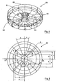
- FIG. 8 An alternative endoscope carrier 60 for use in the apparatus as described above is provided in Figs 8 to 16 .
- the endoscope carrier 60 comprises arms 61 extending radially from a central circular receptacle 62 to an outer perimeter 63.
- the endoscope carrier is connected to an endoscope carrier mounting of the rotary shaft (see Figs 1 , 2 and 5 ) via the receptacle.
- Retainer bars 64 located at various positions on the arms are designed to hold an endoscope in position.
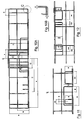
- the endoscope carrier has a fully welded construction, details of which are provided in Fig. 9 to 16 .
- the exemplar endoscope carrier shown in Fig. 10A has a radius of about 222 mm and a maximum depth of about 90 mm.
- endoscopes are positioned within the endoscope carrier (not shown).
- An endoscope carrier is connected to a rotary shaft mounting on each side of the rotary shaft, whereupon the outer perimeters of two connected and adjacent endoscope carriers form a contact seal.
Claims (15)
- Appareil de retraitement d'endoscope (1) comprenant une chambre de retraitement (3), un support (5) auquel un dispositif porteur d'endoscope (6) est fixé, un premier moyen de retraitement disposé sur ou dans une surface interne de la chambre de retraitement, et une source de fluide de retraitement (10A-C) en communication fluide avec le premier moyen de retraitement, un connecteur (52) en communication fluide avec la source de fluide de retraitement, le connecteur fixable à une extrémité de l'endoscope pour permettre au fluide de retraitement d'entrer en contact avec un canal interne de l'endoscope, caractérisé en ce que le support est situé à l'intérieur de la chambre de retraitement et le connecteur est contigu au support, et où le dispositif porteur d'endoscope est pivotable par rapport à la chambre de retraitement de telle manière à ce que le fluide de retraitement émis à partir du premier moyen de retraitement entre en contact, à des angles différents, avec un endoscope positionné sur ou dans le dispositif porteur d'endoscope.
- Appareil selon la revendication 1 dans lequel le premier moyen de retraitement est disposé pour permettre au fluide de retraitement émis à partir de celui-ci de retraiter une surface externe de l'endoscope.
- Appareil selon une quelconque revendication précédente, dans lequel le support s'engage avec un arbre rotatif (4) disposé à l'intérieur de la chambre de retraitement.
- Appareil selon une quelconque revendication précédente, dans lequel le dispositif porteur d'endoscope est pivoté par rapport à la chambre de retraitement par le fluide de retraitement émis à partir du premier moyen de retraitement.
- Appareil selon une quelconque revendication précédente, dans lequel la chambre de retraitement comprend une sortie (30) pour le drainage du fluide de retraitement et la sortie est en communication fluide avec une soupape de drainage rotative (31).
- Appareil selon la revendication 5, dans lequel la soupape de drainage rotative comprend un conduit d'indexage pivotable pour s'aligner sur l'un d'une pluralité de conduits de sortie en communication fluide avec la source de fluide de retraitement et/ou extracteur de gaz.
- Appareil selon une quelconque revendication précédente, dans lequel le dispositif porteur d'endoscope comprend une crémaillère (7).
- Appareil selon une quelconque des revendications de 1 à 6, dans lequel le dispositif porteur d'endoscope est une cartouche.
- Appareil selon la revendication 8, dans lequel la cartouche comprend un second moyen de retraitement disposé sur ou dans une surface interne de la cartouche et en communication fluide avec la source de fluide de retraitement.
- Appareil selon l'une ou l'autre de la revendication 8 ou revendication 9, dans lequel la cartouche s'engage avec le connecteur comme défini dans une quelconque des revendications de 1 à 9 pour permettre au fluide de retraitement d'entrer en contact avec un canal d'un endoscope logé à l'intérieur de la cartouche et/ou pour fournir des moyens de communication fluide entre la source de fluide de retraitement et le second moyen de retraitement.
- Appareil selon une quelconque des revendications précédentes dans lequel la source de fluide de retraitement en communication fluide avec le connecteur est indépendante ou opérationnelle et liée à la source de fluide de retraitement en communication fluide avec le premier moyen de retraitement.
- Appareil selon une quelconque des revendications précédentes dans lequel le dispositif porteur d'endoscope (6) est pivoté par rapport à la chambre de retraitement jusqu'à 360 degrés, par exemple jusqu'à 180 degrés.
- Appareil selon une quelconque des revendications précédentes où la chambre de retraitement (3) est circulaire.
- Appareil selon une quelconque des revendications précédentes où le premier moyen de retraitement est pivotable à l'intérieur de la chambre de retraitement.
- Méthode pour retraiter un endoscope comprenant l'étape consistant à soumettre l'endoscope à un cycle de retraitement à l'intérieur d'un appareil de retraitement d'endoscope comme défini dans une quelconque des revendications précédentes.
Applications Claiming Priority (2)
| Application Number | Priority Date | Filing Date | Title |
|---|---|---|---|
| GBGB0520551.3A GB0520551D0 (en) | 2005-10-10 | 2005-10-10 | Reprocessing apparatus |
| PCT/GB2006/003753 WO2007042787A2 (fr) | 2005-10-10 | 2006-10-10 | Appareil de retraitement |
Publications (2)
| Publication Number | Publication Date |
|---|---|
| EP1945276A2 EP1945276A2 (fr) | 2008-07-23 |
| EP1945276B1 true EP1945276B1 (fr) | 2010-06-23 |
Family
ID=35430094
Family Applications (1)
| Application Number | Title | Priority Date | Filing Date |
|---|---|---|---|
| EP06794704A Not-in-force EP1945276B1 (fr) | 2005-10-10 | 2006-10-10 | Appareil de retraitement |
Country Status (8)
| Country | Link |
|---|---|
| EP (1) | EP1945276B1 (fr) |
| AT (1) | ATE471726T1 (fr) |
| AU (1) | AU2006300929B2 (fr) |
| CA (1) | CA2625484A1 (fr) |
| DE (1) | DE602006015083D1 (fr) |
| GB (1) | GB0520551D0 (fr) |
| NZ (1) | NZ567949A (fr) |
| WO (1) | WO2007042787A2 (fr) |
Families Citing this family (13)
| Publication number | Priority date | Publication date | Assignee | Title |
|---|---|---|---|---|
| US20130098407A1 (en) * | 2011-10-21 | 2013-04-25 | Timothy J. Perlman | Instrument reprocessors, systems, and methods |
| DE102014119262B4 (de) * | 2014-12-19 | 2019-06-19 | Vanguard Ag | Berührungsloser Sterilisierungskatheter |
| NL1041124B1 (nl) * | 2014-12-22 | 2016-09-30 | Anne Kemkers Frederikus | Inrichting en werkwijze voor het behandelen van doorgaande holtes van gereedschappen. |
| CN104826142A (zh) * | 2015-05-09 | 2015-08-12 | 韩兆东 | 检验科设备清洁消毒装置 |
| CN109365374A (zh) * | 2018-12-11 | 2019-02-22 | 薛文霞 | 妇科工具预清洗柜 |
| CN109701129B (zh) * | 2019-01-16 | 2021-04-20 | 汕头大学医学院第一附属医院 | 一种小儿专用雾化器 |
| CN109876172B (zh) * | 2019-04-18 | 2020-07-24 | 青岛市妇女儿童医院(青岛市妇幼保健院、青岛市残疾儿童医疗康复中心、青岛市新生儿疾病筛查中心) | 一种新式妇产科器械消毒一体装置 |
| CN111001023A (zh) * | 2019-12-18 | 2020-04-14 | 南通市第一人民医院 | 一种具有烘干结构的急救护理用品消毒装置及使用方法 |
| CN111166504B (zh) * | 2019-12-31 | 2022-01-07 | 陈镇 | 一种内窥镜清洗消毒装置 |
| CN111265691A (zh) * | 2020-02-18 | 2020-06-12 | 台州市立医院 | 一种医疗器械用消毒装置 |
| CN111265695B (zh) * | 2020-03-24 | 2021-02-02 | 北菱电梯股份有限公司 | 一种电梯按钮杀菌装置 |
| CN111686272A (zh) * | 2020-05-19 | 2020-09-22 | 黄平平 | 一种医疗器具用的消毒沥干装置 |
| CN113952492A (zh) * | 2021-10-09 | 2022-01-21 | 山东第一医科大学附属省立医院(山东省立医院) | 一种智能雾化护理抑菌装置 |
Family Cites Families (6)
| Publication number | Priority date | Publication date | Assignee | Title |
|---|---|---|---|---|
| US3893843A (en) * | 1970-06-24 | 1975-07-08 | Arbrook Inc | Method for washing and disinfecting hollow, flexible articles |
| DE2552011C3 (de) * | 1975-11-20 | 1980-08-07 | Riwoplan Medizin-Technische Einrichtungsgesellschaft Mbh, 7134 Knittlingen | Reinigungsgerät für medizinische Instrumente * |
| US4447399A (en) * | 1981-05-07 | 1984-05-08 | Mdt Chemical Company | Combination steam and unsaturated chemical vapor sterilizer |
| JPS58155833A (ja) | 1982-03-11 | 1983-09-16 | オリンパス光学工業株式会社 | 内視鏡用洗浄装置 |
| US4763678A (en) * | 1986-12-30 | 1988-08-16 | Mayo Medical Resources | Cleaning apparatus for elongated enclosed channel devices |
| ATE279218T1 (de) | 2000-02-07 | 2004-10-15 | Steris Inc | Verfahren und vorrichtung zum flüssig-reinigen und -sterilisieren |
-
2005
- 2005-10-10 GB GBGB0520551.3A patent/GB0520551D0/en not_active Ceased
-
2006
- 2006-10-10 AU AU2006300929A patent/AU2006300929B2/en not_active Ceased
- 2006-10-10 DE DE602006015083T patent/DE602006015083D1/de active Active
- 2006-10-10 WO PCT/GB2006/003753 patent/WO2007042787A2/fr active Application Filing
- 2006-10-10 EP EP06794704A patent/EP1945276B1/fr not_active Not-in-force
- 2006-10-10 NZ NZ567949A patent/NZ567949A/en not_active IP Right Cessation
- 2006-10-10 AT AT06794704T patent/ATE471726T1/de not_active IP Right Cessation
- 2006-10-10 CA CA002625484A patent/CA2625484A1/fr not_active Abandoned
Also Published As
| Publication number | Publication date |
|---|---|
| EP1945276A2 (fr) | 2008-07-23 |
| WO2007042787A3 (fr) | 2007-11-15 |
| WO2007042787A2 (fr) | 2007-04-19 |
| AU2006300929B2 (en) | 2012-05-03 |
| NZ567949A (en) | 2010-09-30 |
| GB0520551D0 (en) | 2005-11-16 |
| DE602006015083D1 (de) | 2010-08-05 |
| ATE471726T1 (de) | 2010-07-15 |
| AU2006300929A1 (en) | 2007-04-19 |
| CA2625484A1 (fr) | 2007-04-19 |
Similar Documents
| Publication | Publication Date | Title |
|---|---|---|
| EP1945276B1 (fr) | Appareil de retraitement | |
| CN107398456B (zh) | 用于再处理医疗装置的设备和方法 | |
| US5882589A (en) | Sealed endoscope decontamination, disinfection and drying device | |
| JP4184980B2 (ja) | 自動化内視鏡再処理機 | |
| JP5064020B2 (ja) | キャビネット型内視鏡プロセッサ | |
| US5795404A (en) | Method and apparatus for cleaning channels of an endoscope | |
| US6286527B1 (en) | Reverse flow cleaning and sterilizing device and method | |
| KR101907353B1 (ko) | 의료용 자동세척장치 | |
| JP2002507905A (ja) | 医療用具を滅菌する装置および方法 | |
| EP0549674A1 (fr) | Nettoyage et desinfection d'instruments medicaux. | |
| EP1803470B1 (fr) | Récipient de stockage pour nettoyer/stériliser des endoscopes | |
| AU2011308621B2 (en) | Device for disinfecting and/or rinsing endoscopes with limited escape of fumes | |
| EP0835665A2 (fr) | Appareil de désinfection, nettoyage, neutralisation et séchage automatique d'articles médicaux | |
| JP4757178B2 (ja) | 内視鏡洗浄消毒装置、及び内視鏡洗浄消毒装置の装置内管路の消毒方法。 | |
| Babb et al. | Comparison of automated systems for the cleaning and disinfection of flexible fibreoptic endoscopes |
Legal Events
| Date | Code | Title | Description |
|---|---|---|---|
| PUAI | Public reference made under article 153(3) epc to a published international application that has entered the european phase |
Free format text: ORIGINAL CODE: 0009012 |
|
| 17P | Request for examination filed |
Effective date: 20080508 |
|
| AK | Designated contracting states |
Kind code of ref document: A2 Designated state(s): AT BE BG CH CY CZ DE DK EE ES FI FR GB GR HU IE IS IT LI LT LU LV MC NL PL PT RO SE SI SK TR |
|
| 17Q | First examination report despatched |
Effective date: 20080806 |
|
| GRAP | Despatch of communication of intention to grant a patent |
Free format text: ORIGINAL CODE: EPIDOSNIGR1 |
|
| DAX | Request for extension of the european patent (deleted) | ||
| GRAS | Grant fee paid |
Free format text: ORIGINAL CODE: EPIDOSNIGR3 |
|
| RAP1 | Party data changed (applicant data changed or rights of an application transferred) |
Owner name: PURICORE INC. |
|
| RAP1 | Party data changed (applicant data changed or rights of an application transferred) |
Owner name: PURICORE, INC. |
|
| GRAA | (expected) grant |
Free format text: ORIGINAL CODE: 0009210 |
|
| AK | Designated contracting states |
Kind code of ref document: B1 Designated state(s): AT BE BG CH CY CZ DE DK EE ES FI FR GB GR HU IE IS IT LI LT LU LV MC NL PL PT RO SE SI SK TR |
|
| REG | Reference to a national code |
Ref country code: CH Ref legal event code: EP |
|
| REG | Reference to a national code |
Ref country code: IE Ref legal event code: FG4D |
|
| REF | Corresponds to: |
Ref document number: 602006015083 Country of ref document: DE Date of ref document: 20100805 Kind code of ref document: P |
|
| REG | Reference to a national code |
Ref country code: NL Ref legal event code: T3 |
|
| REG | Reference to a national code |
Ref country code: SE Ref legal event code: TRGR |
|
| PG25 | Lapsed in a contracting state [announced via postgrant information from national office to epo] |
Ref country code: LT Free format text: LAPSE BECAUSE OF FAILURE TO SUBMIT A TRANSLATION OF THE DESCRIPTION OR TO PAY THE FEE WITHIN THE PRESCRIBED TIME-LIMIT Effective date: 20100623 |
|
| LTIE | Lt: invalidation of european patent or patent extension |
Effective date: 20100623 |
|
| PG25 | Lapsed in a contracting state [announced via postgrant information from national office to epo] |
Ref country code: AT Free format text: LAPSE BECAUSE OF FAILURE TO SUBMIT A TRANSLATION OF THE DESCRIPTION OR TO PAY THE FEE WITHIN THE PRESCRIBED TIME-LIMIT Effective date: 20100623 Ref country code: SI Free format text: LAPSE BECAUSE OF FAILURE TO SUBMIT A TRANSLATION OF THE DESCRIPTION OR TO PAY THE FEE WITHIN THE PRESCRIBED TIME-LIMIT Effective date: 20100623 Ref country code: LV Free format text: LAPSE BECAUSE OF FAILURE TO SUBMIT A TRANSLATION OF THE DESCRIPTION OR TO PAY THE FEE WITHIN THE PRESCRIBED TIME-LIMIT Effective date: 20100623 Ref country code: FI Free format text: LAPSE BECAUSE OF FAILURE TO SUBMIT A TRANSLATION OF THE DESCRIPTION OR TO PAY THE FEE WITHIN THE PRESCRIBED TIME-LIMIT Effective date: 20100623 |
|
| PG25 | Lapsed in a contracting state [announced via postgrant information from national office to epo] |
Ref country code: PL Free format text: LAPSE BECAUSE OF FAILURE TO SUBMIT A TRANSLATION OF THE DESCRIPTION OR TO PAY THE FEE WITHIN THE PRESCRIBED TIME-LIMIT Effective date: 20100623 Ref country code: GR Free format text: LAPSE BECAUSE OF FAILURE TO SUBMIT A TRANSLATION OF THE DESCRIPTION OR TO PAY THE FEE WITHIN THE PRESCRIBED TIME-LIMIT Effective date: 20100924 |
|
| PG25 | Lapsed in a contracting state [announced via postgrant information from national office to epo] |
Ref country code: EE Free format text: LAPSE BECAUSE OF FAILURE TO SUBMIT A TRANSLATION OF THE DESCRIPTION OR TO PAY THE FEE WITHIN THE PRESCRIBED TIME-LIMIT Effective date: 20100623 |
|
| PG25 | Lapsed in a contracting state [announced via postgrant information from national office to epo] |
Ref country code: SK Free format text: LAPSE BECAUSE OF FAILURE TO SUBMIT A TRANSLATION OF THE DESCRIPTION OR TO PAY THE FEE WITHIN THE PRESCRIBED TIME-LIMIT Effective date: 20100623 Ref country code: RO Free format text: LAPSE BECAUSE OF FAILURE TO SUBMIT A TRANSLATION OF THE DESCRIPTION OR TO PAY THE FEE WITHIN THE PRESCRIBED TIME-LIMIT Effective date: 20100623 Ref country code: IS Free format text: LAPSE BECAUSE OF FAILURE TO SUBMIT A TRANSLATION OF THE DESCRIPTION OR TO PAY THE FEE WITHIN THE PRESCRIBED TIME-LIMIT Effective date: 20101023 Ref country code: CZ Free format text: LAPSE BECAUSE OF FAILURE TO SUBMIT A TRANSLATION OF THE DESCRIPTION OR TO PAY THE FEE WITHIN THE PRESCRIBED TIME-LIMIT Effective date: 20100623 Ref country code: CY Free format text: LAPSE BECAUSE OF FAILURE TO SUBMIT A TRANSLATION OF THE DESCRIPTION OR TO PAY THE FEE WITHIN THE PRESCRIBED TIME-LIMIT Effective date: 20100623 Ref country code: BE Free format text: LAPSE BECAUSE OF FAILURE TO SUBMIT A TRANSLATION OF THE DESCRIPTION OR TO PAY THE FEE WITHIN THE PRESCRIBED TIME-LIMIT Effective date: 20100623 |
|
| PG25 | Lapsed in a contracting state [announced via postgrant information from national office to epo] |
Ref country code: IT Free format text: LAPSE BECAUSE OF FAILURE TO SUBMIT A TRANSLATION OF THE DESCRIPTION OR TO PAY THE FEE WITHIN THE PRESCRIBED TIME-LIMIT Effective date: 20100623 |
|
| PG25 | Lapsed in a contracting state [announced via postgrant information from national office to epo] |
Ref country code: DK Free format text: LAPSE BECAUSE OF FAILURE TO SUBMIT A TRANSLATION OF THE DESCRIPTION OR TO PAY THE FEE WITHIN THE PRESCRIBED TIME-LIMIT Effective date: 20100623 |
|
| PLBE | No opposition filed within time limit |
Free format text: ORIGINAL CODE: 0009261 |
|
| STAA | Information on the status of an ep patent application or granted ep patent |
Free format text: STATUS: NO OPPOSITION FILED WITHIN TIME LIMIT |
|
| PG25 | Lapsed in a contracting state [announced via postgrant information from national office to epo] |
Ref country code: MC Free format text: LAPSE BECAUSE OF NON-PAYMENT OF DUE FEES Effective date: 20101031 |
|
| REG | Reference to a national code |
Ref country code: CH Ref legal event code: PL |
|
| 26N | No opposition filed |
Effective date: 20110324 |
|
| REG | Reference to a national code |
Ref country code: NL Ref legal event code: SD Effective date: 20110601 |
|
| REG | Reference to a national code |
Ref country code: DE Ref legal event code: R097 Ref document number: 602006015083 Country of ref document: DE Effective date: 20110323 |
|
| REG | Reference to a national code |
Ref country code: DE Ref legal event code: R082 Ref document number: 602006015083 Country of ref document: DE Representative=s name: MEISSNER, BOLTE & PARTNER GBR, DE Effective date: 20110608 Ref country code: DE Ref legal event code: R081 Ref document number: 602006015083 Country of ref document: DE Owner name: PURICORE INTERNATIONAL LTD., GB Free format text: FORMER OWNER: PURICORE, INC., MALVERN, US Effective date: 20110608 Ref country code: DE Ref legal event code: R081 Ref document number: 602006015083 Country of ref document: DE Owner name: PURICORE INTERNATIONAL LTD., GB Free format text: FORMER OWNER: PURICORE, INC., MALVERN, PA., US Effective date: 20110608 Ref country code: DE Ref legal event code: R082 Ref document number: 602006015083 Country of ref document: DE Representative=s name: MEISSNER BOLTE PATENTANWAELTE RECHTSANWAELTE P, DE Effective date: 20110608 Ref country code: DE Ref legal event code: R081 Ref document number: 602006015083 Country of ref document: DE Owner name: CANTEL (UK) LIMITED, SOUTHEND-ON-SEA, GB Free format text: FORMER OWNER: PURICORE, INC., MALVERN, PA., US Effective date: 20110608 |
|
| PG25 | Lapsed in a contracting state [announced via postgrant information from national office to epo] |
Ref country code: CH Free format text: LAPSE BECAUSE OF NON-PAYMENT OF DUE FEES Effective date: 20101031 Ref country code: LI Free format text: LAPSE BECAUSE OF NON-PAYMENT OF DUE FEES Effective date: 20101031 |
|
| REG | Reference to a national code |
Ref country code: GB Ref legal event code: 732E Free format text: REGISTERED BETWEEN 20110707 AND 20110713 |
|
| PG25 | Lapsed in a contracting state [announced via postgrant information from national office to epo] |
Ref country code: IE Free format text: LAPSE BECAUSE OF NON-PAYMENT OF DUE FEES Effective date: 20101010 |
|
| PG25 | Lapsed in a contracting state [announced via postgrant information from national office to epo] |
Ref country code: LU Free format text: LAPSE BECAUSE OF NON-PAYMENT OF DUE FEES Effective date: 20101010 Ref country code: BG Free format text: LAPSE BECAUSE OF FAILURE TO SUBMIT A TRANSLATION OF THE DESCRIPTION OR TO PAY THE FEE WITHIN THE PRESCRIBED TIME-LIMIT Effective date: 20100623 Ref country code: HU Free format text: LAPSE BECAUSE OF FAILURE TO SUBMIT A TRANSLATION OF THE DESCRIPTION OR TO PAY THE FEE WITHIN THE PRESCRIBED TIME-LIMIT Effective date: 20101224 |
|
| PG25 | Lapsed in a contracting state [announced via postgrant information from national office to epo] |
Ref country code: TR Free format text: LAPSE BECAUSE OF FAILURE TO SUBMIT A TRANSLATION OF THE DESCRIPTION OR TO PAY THE FEE WITHIN THE PRESCRIBED TIME-LIMIT Effective date: 20100623 |
|
| PG25 | Lapsed in a contracting state [announced via postgrant information from national office to epo] |
Ref country code: PT Free format text: LAPSE BECAUSE OF NON-PAYMENT OF DUE FEES Effective date: 20100623 |
|
| PG25 | Lapsed in a contracting state [announced via postgrant information from national office to epo] |
Ref country code: BG Free format text: LAPSE BECAUSE OF FAILURE TO SUBMIT A TRANSLATION OF THE DESCRIPTION OR TO PAY THE FEE WITHIN THE PRESCRIBED TIME-LIMIT Effective date: 20100923 |
|
| PG25 | Lapsed in a contracting state [announced via postgrant information from national office to epo] |
Ref country code: ES Free format text: LAPSE BECAUSE OF FAILURE TO SUBMIT A TRANSLATION OF THE DESCRIPTION OR TO PAY THE FEE WITHIN THE PRESCRIBED TIME-LIMIT Effective date: 20101004 |
|
| REG | Reference to a national code |
Ref country code: DE Ref legal event code: R082 Ref document number: 602006015083 Country of ref document: DE Representative=s name: MEISSNER BOLTE PATENTANWAELTE RECHTSANWAELTE P, DE Ref country code: DE Ref legal event code: R082 Ref document number: 602006015083 Country of ref document: DE Representative=s name: MEISSNER, BOLTE & PARTNER GBR, DE |
|
| REG | Reference to a national code |
Ref country code: DE Ref legal event code: R082 Ref document number: 602006015083 Country of ref document: DE Representative=s name: MEISSNER, BOLTE & PARTNER GBR, DE |
|
| REG | Reference to a national code |
Ref country code: GB Ref legal event code: 732E Free format text: REGISTERED BETWEEN 20140123 AND 20140129 |
|
| REG | Reference to a national code |
Ref country code: FR Ref legal event code: PLFP Year of fee payment: 10 |
|
| REG | Reference to a national code |
Ref country code: FR Ref legal event code: PLFP Year of fee payment: 11 |
|
| REG | Reference to a national code |
Ref country code: FR Ref legal event code: PLFP Year of fee payment: 12 |
|
| REG | Reference to a national code |
Ref country code: DE Ref legal event code: R082 Ref document number: 602006015083 Country of ref document: DE Representative=s name: MEISSNER BOLTE PATENTANWAELTE RECHTSANWAELTE P, DE Ref country code: DE Ref legal event code: R081 Ref document number: 602006015083 Country of ref document: DE Owner name: CANTEL (UK) LIMITED, SOUTHEND-ON-SEA, GB Free format text: FORMER OWNER: PURICORE INTERNATIONAL LTD., STAFFORD, GB |
|
| REG | Reference to a national code |
Ref country code: GB Ref legal event code: 732E Free format text: REGISTERED BETWEEN 20180104 AND 20180110 |
|
| REG | Reference to a national code |
Ref country code: NL Ref legal event code: HC Owner name: CANTEL MEDICAL (UK) LIMITED; GB Free format text: DETAILS ASSIGNMENT: CHANGE OF OWNER(S), CHANGE OF OWNER(S) NAME; FORMER OWNER NAME: PURICORE INTERNATIONAL LIMITED Effective date: 20180117 Ref country code: NL Ref legal event code: PD Owner name: CANTEL (UK) LIMITED; GB Free format text: DETAILS ASSIGNMENT: CHANGE OF OWNER(S), ASSIGNMENT; FORMER OWNER NAME: CANTEL MEDICAL (UK) LIMITED Effective date: 20180117 |
|
| REG | Reference to a national code |
Ref country code: FR Ref legal event code: CD Owner name: CANTEL (UK) LIMITED, GB Effective date: 20180330 Ref country code: FR Ref legal event code: TP Owner name: CANTEL (UK) LIMITED, GB Effective date: 20180330 |
|
| REG | Reference to a national code |
Ref country code: FR Ref legal event code: PLFP Year of fee payment: 13 |
|
| PGFP | Annual fee paid to national office [announced via postgrant information from national office to epo] |
Ref country code: NL Payment date: 20181026 Year of fee payment: 13 |
|
| PGFP | Annual fee paid to national office [announced via postgrant information from national office to epo] |
Ref country code: DE Payment date: 20181029 Year of fee payment: 13 Ref country code: SE Payment date: 20181029 Year of fee payment: 13 |
|
| PGFP | Annual fee paid to national office [announced via postgrant information from national office to epo] |
Ref country code: GB Payment date: 20181029 Year of fee payment: 13 Ref country code: FR Payment date: 20181025 Year of fee payment: 13 |
|
| REG | Reference to a national code |
Ref country code: DE Ref legal event code: R119 Ref document number: 602006015083 Country of ref document: DE |
|
| REG | Reference to a national code |
Ref country code: NL Ref legal event code: MM Effective date: 20191101 |
|
| PG25 | Lapsed in a contracting state [announced via postgrant information from national office to epo] |
Ref country code: DE Free format text: LAPSE BECAUSE OF NON-PAYMENT OF DUE FEES Effective date: 20200501 |
|
| PG25 | Lapsed in a contracting state [announced via postgrant information from national office to epo] |
Ref country code: SE Free format text: LAPSE BECAUSE OF NON-PAYMENT OF DUE FEES Effective date: 20191011 Ref country code: NL Free format text: LAPSE BECAUSE OF NON-PAYMENT OF DUE FEES Effective date: 20191101 |
|
| GBPC | Gb: european patent ceased through non-payment of renewal fee |
Effective date: 20191010 |
|
| PG25 | Lapsed in a contracting state [announced via postgrant information from national office to epo] |
Ref country code: GB Free format text: LAPSE BECAUSE OF NON-PAYMENT OF DUE FEES Effective date: 20191010 Ref country code: FR Free format text: LAPSE BECAUSE OF NON-PAYMENT OF DUE FEES Effective date: 20191031 |