EP1944893A1 - Radio transmitter, radio communication system, and radio transmission method - Google Patents
Radio transmitter, radio communication system, and radio transmission method Download PDFInfo
- Publication number
- EP1944893A1 EP1944893A1 EP06822663A EP06822663A EP1944893A1 EP 1944893 A1 EP1944893 A1 EP 1944893A1 EP 06822663 A EP06822663 A EP 06822663A EP 06822663 A EP06822663 A EP 06822663A EP 1944893 A1 EP1944893 A1 EP 1944893A1
- Authority
- EP
- European Patent Office
- Prior art keywords
- frequency
- transmission
- radio
- diversity region
- chunks
- Prior art date
- Legal status (The legal status is an assumption and is not a legal conclusion. Google has not performed a legal analysis and makes no representation as to the accuracy of the status listed.)
- Granted
Links
Images









Classifications
-
- H—ELECTRICITY
- H04—ELECTRIC COMMUNICATION TECHNIQUE
- H04W—WIRELESS COMMUNICATION NETWORKS
- H04W72/00—Local resource management
- H04W72/04—Wireless resource allocation
-
- H—ELECTRICITY
- H04—ELECTRIC COMMUNICATION TECHNIQUE
- H04B—TRANSMISSION
- H04B7/00—Radio transmission systems, i.e. using radiation field
- H04B7/02—Diversity systems; Multi-antenna system, i.e. transmission or reception using multiple antennas
- H04B7/04—Diversity systems; Multi-antenna system, i.e. transmission or reception using multiple antennas using two or more spaced independent antennas
-
- H—ELECTRICITY
- H04—ELECTRIC COMMUNICATION TECHNIQUE
- H04B—TRANSMISSION
- H04B7/00—Radio transmission systems, i.e. using radiation field
- H04B7/02—Diversity systems; Multi-antenna system, i.e. transmission or reception using multiple antennas
- H04B7/04—Diversity systems; Multi-antenna system, i.e. transmission or reception using multiple antennas using two or more spaced independent antennas
- H04B7/0413—MIMO systems
- H04B7/0452—Multi-user MIMO systems
-
- H—ELECTRICITY
- H04—ELECTRIC COMMUNICATION TECHNIQUE
- H04B—TRANSMISSION
- H04B7/00—Radio transmission systems, i.e. using radiation field
- H04B7/02—Diversity systems; Multi-antenna system, i.e. transmission or reception using multiple antennas
- H04B7/04—Diversity systems; Multi-antenna system, i.e. transmission or reception using multiple antennas using two or more spaced independent antennas
- H04B7/06—Diversity systems; Multi-antenna system, i.e. transmission or reception using multiple antennas using two or more spaced independent antennas at the transmitting station
- H04B7/0686—Hybrid systems, i.e. switching and simultaneous transmission
- H04B7/0689—Hybrid systems, i.e. switching and simultaneous transmission using different transmission schemes, at least one of them being a diversity transmission scheme
-
- H—ELECTRICITY
- H04—ELECTRIC COMMUNICATION TECHNIQUE
- H04B—TRANSMISSION
- H04B7/00—Radio transmission systems, i.e. using radiation field
- H04B7/02—Diversity systems; Multi-antenna system, i.e. transmission or reception using multiple antennas
- H04B7/12—Frequency diversity
-
- H—ELECTRICITY
- H04—ELECTRIC COMMUNICATION TECHNIQUE
- H04L—TRANSMISSION OF DIGITAL INFORMATION, e.g. TELEGRAPHIC COMMUNICATION
- H04L27/00—Modulated-carrier systems
- H04L27/26—Systems using multi-frequency codes
- H04L27/2601—Multicarrier modulation systems
-
- H—ELECTRICITY
- H04—ELECTRIC COMMUNICATION TECHNIQUE
- H04L—TRANSMISSION OF DIGITAL INFORMATION, e.g. TELEGRAPHIC COMMUNICATION
- H04L5/00—Arrangements affording multiple use of the transmission path
- H04L5/003—Arrangements for allocating sub-channels of the transmission path
- H04L5/0053—Allocation of signalling, i.e. of overhead other than pilot signals
- H04L5/0057—Physical resource allocation for CQI
-
- H—ELECTRICITY
- H04—ELECTRIC COMMUNICATION TECHNIQUE
- H04B—TRANSMISSION
- H04B7/00—Radio transmission systems, i.e. using radiation field
- H04B7/02—Diversity systems; Multi-antenna system, i.e. transmission or reception using multiple antennas
- H04B7/04—Diversity systems; Multi-antenna system, i.e. transmission or reception using multiple antennas using two or more spaced independent antennas
- H04B7/0413—MIMO systems
-
- H—ELECTRICITY
- H04—ELECTRIC COMMUNICATION TECHNIQUE
- H04B—TRANSMISSION
- H04B7/00—Radio transmission systems, i.e. using radiation field
- H04B7/02—Diversity systems; Multi-antenna system, i.e. transmission or reception using multiple antennas
- H04B7/04—Diversity systems; Multi-antenna system, i.e. transmission or reception using multiple antennas using two or more spaced independent antennas
- H04B7/06—Diversity systems; Multi-antenna system, i.e. transmission or reception using multiple antennas using two or more spaced independent antennas at the transmitting station
- H04B7/0602—Diversity systems; Multi-antenna system, i.e. transmission or reception using multiple antennas using two or more spaced independent antennas at the transmitting station using antenna switching
-
- H—ELECTRICITY
- H04—ELECTRIC COMMUNICATION TECHNIQUE
- H04B—TRANSMISSION
- H04B7/00—Radio transmission systems, i.e. using radiation field
- H04B7/02—Diversity systems; Multi-antenna system, i.e. transmission or reception using multiple antennas
- H04B7/04—Diversity systems; Multi-antenna system, i.e. transmission or reception using multiple antennas using two or more spaced independent antennas
- H04B7/06—Diversity systems; Multi-antenna system, i.e. transmission or reception using multiple antennas using two or more spaced independent antennas at the transmitting station
- H04B7/0602—Diversity systems; Multi-antenna system, i.e. transmission or reception using multiple antennas using two or more spaced independent antennas at the transmitting station using antenna switching
- H04B7/0608—Antenna selection according to transmission parameters
-
- H—ELECTRICITY
- H04—ELECTRIC COMMUNICATION TECHNIQUE
- H04B—TRANSMISSION
- H04B7/00—Radio transmission systems, i.e. using radiation field
- H04B7/02—Diversity systems; Multi-antenna system, i.e. transmission or reception using multiple antennas
- H04B7/04—Diversity systems; Multi-antenna system, i.e. transmission or reception using multiple antennas using two or more spaced independent antennas
- H04B7/06—Diversity systems; Multi-antenna system, i.e. transmission or reception using multiple antennas using two or more spaced independent antennas at the transmitting station
- H04B7/0613—Diversity systems; Multi-antenna system, i.e. transmission or reception using multiple antennas using two or more spaced independent antennas at the transmitting station using simultaneous transmission
- H04B7/0667—Diversity systems; Multi-antenna system, i.e. transmission or reception using multiple antennas using two or more spaced independent antennas at the transmitting station using simultaneous transmission of delayed versions of same signal
- H04B7/0671—Diversity systems; Multi-antenna system, i.e. transmission or reception using multiple antennas using two or more spaced independent antennas at the transmitting station using simultaneous transmission of delayed versions of same signal using different delays between antennas
-
- H—ELECTRICITY
- H04—ELECTRIC COMMUNICATION TECHNIQUE
- H04L—TRANSMISSION OF DIGITAL INFORMATION, e.g. TELEGRAPHIC COMMUNICATION
- H04L25/00—Baseband systems
- H04L25/02—Details ; arrangements for supplying electrical power along data transmission lines
- H04L25/03—Shaping networks in transmitter or receiver, e.g. adaptive shaping networks
- H04L25/03006—Arrangements for removing intersymbol interference
- H04L2025/0335—Arrangements for removing intersymbol interference characterised by the type of transmission
- H04L2025/03375—Passband transmission
- H04L2025/03414—Multicarrier
-
- H—ELECTRICITY
- H04—ELECTRIC COMMUNICATION TECHNIQUE
- H04L—TRANSMISSION OF DIGITAL INFORMATION, e.g. TELEGRAPHIC COMMUNICATION
- H04L25/00—Baseband systems
- H04L25/02—Details ; arrangements for supplying electrical power along data transmission lines
- H04L25/03—Shaping networks in transmitter or receiver, e.g. adaptive shaping networks
- H04L25/03006—Arrangements for removing intersymbol interference
- H04L2025/0335—Arrangements for removing intersymbol interference characterised by the type of transmission
- H04L2025/03426—Arrangements for removing intersymbol interference characterised by the type of transmission transmission using multiple-input and multiple-output channels
-
- H—ELECTRICITY
- H04—ELECTRIC COMMUNICATION TECHNIQUE
- H04L—TRANSMISSION OF DIGITAL INFORMATION, e.g. TELEGRAPHIC COMMUNICATION
- H04L5/00—Arrangements affording multiple use of the transmission path
- H04L5/0001—Arrangements for dividing the transmission path
- H04L5/0014—Three-dimensional division
- H04L5/0023—Time-frequency-space
-
- H—ELECTRICITY
- H04—ELECTRIC COMMUNICATION TECHNIQUE
- H04L—TRANSMISSION OF DIGITAL INFORMATION, e.g. TELEGRAPHIC COMMUNICATION
- H04L5/00—Arrangements affording multiple use of the transmission path
- H04L5/0091—Signalling for the administration of the divided path, e.g. signalling of configuration information
- H04L5/0094—Indication of how sub-channels of the path are allocated
Definitions
- the present invention relates to radio transmitters, radio communication systems, and radio transmission methods and in particular to transmitters and transmission methods for transmitting signals to radio receivers via multiple transmission antennas.
- the present application claims priority on Japanese Patent Application No. 2005-317266 filed in Japan on October 31, 2005 , the content of which is incorporated herein by reference.
- blocks that are broadened in frequency axes are assigned so as to get frequency diversity effects, thus making it difficult to cause errors in received signals even when received power is low; and in transmission of unicast signals via one-to-one communications between radio transmitters and radio receivers, blocks that are broadened in frequency axes are assigned so as to get multiuser diversity effects.
- FIGS. 31 and 32 are drawings showing the relationships of signals, which are transmitted from radio transmitters to radio receivers, with reference to time (vertical axis) and frequency (horizontal axis).
- Transmission times t1 to t5 are set to the time axis.
- the transmission times t1 to t5 are identical to each other in time length.
- transmission frequencies f1 to f4 are set to the frequency axis. All the transmission frequencies f1 to f4 have the same frequency band of Fc.
- twenty chunks K1 to K20 are set by way of the transmission times t1 to t5 and the transmission frequencies f1 to f4.
- the chunk K5 is assigned to a fourth user as an assignment slot S4.
- the chunks K6 and K7 are coupled to form an assignment slot S5, which is assigned to a fifth user.
- the chunk K8 is assigned to a sixth user as a slot S6.
- the chunks K9 and K11 are coupled to form an assignment slot S7, which is assigned to a seventh user.
- the chunks K10 and K12 are coupled and then equally divided into three regions so as to set communication slots S8 to S10, each of which has a time length of t3/3 and a frequency band of 2 ⁇ f2.
- the assignment slot S8 is assigned to an eighth user; the assignment slot S9 is assigned to a ninth user; and the assignment slot S 10 is assigned to a tenth user.
- the seventh to tenth users to obtain frequency diversity effects.
- the chunk K13 is assigned to an eleventh user as an assignment slot S11.
- the chunk K14 is assigned to a twelfth user as an assignment slot S12.
- the chunks K15 and K16 are coupled so as to form an assignment slot S13, which is assigned to a thirteenth user.
- the chunks K17 and K19 are coupled so as to form an assignment slot S14, which is assigned to a fourteenth user.
- the chunks K18 and K20 are coupled and then equally divided into three regions so as to form communication slots S15 to S 17, each of which has a time length of t5/3 and a frequency band of 2 ⁇ f2.
- the assignment slot S15 is assigned to a fifteenth user;
- the assignment slot S16 is assigned to a sixteenth user;
- the assignment slot S17 is assigned to a seventeenth user.
- the conventionally-known technology simply performs frequency diversity and multiuser diversity on signals transmitted via a single transmission antenna, thus transmitting signals to a radio receiver. That is, it cannot further improve communication quality by combining the diversities with a transmission diversity using multiple antennas.
- the present invention is made in consideration of the aforementioned circumstances; and it is an object of the present invention to provide a radio transmitter, a radio communication system, and a radio transmission method, which can further improve communication quality with a radio transmitter by use of multiple transmission antennas.
- a radio transmitter of the present invention is provided to solve the aforementioned problem, wherein it has a scheduler for assigning a communication time and a communication frequency to each radio receiver based on quality information of received signals communicated by a radio receiver, a transmission circuit controller for transmitting whether a frequency diversity region or a multiuser diversity region is selected in each chunk, and a transmission circuit for applying different delay times to signals of multiple transmission antennas based on a transmission result of the transmission control circuit.
- the transmission circuit of the radio transmitter of the present invention sets different maximum delay times for transmission antennas in connection with the frequency diversity region and the multiuser diversity region.
- the transmission circuit of the radio transmitter of the present invention set the maximum delay times of the multiple transmission antennas to be larger than 1/Fc in the frequency diversity region and to be smaller than 1/Fc in the multiuser diversity region.
- the transmission circuit of the radio transmitter of the present invention applies the same delay time to each transmission antenna with respect to at least a common pilot signal included in the common chunk via a downlink common data channel.
- the transmission circuit controller of the radio transmitter of the present invention divides the frequency diversity region and the multiuser diversity region on the frequency axis.
- the transmission circuit controller of the radio transmitter of the present invention divides the frequency diversity region and the multiuser diversity region on the time axis.
- the transmission circuit controller of the radio transmitter of the present invention divides the frequency diversity region and the multiuser diversity region on both the frequency axis and the time axis.
- the scheduler of the radio transmitter of the present invention compares received signals of radio receivers in terms of quality information so as to determine the priority order, thus assigning chunks to radio receivers based on the determination result.
- the transmission circuit controller of the radio transmitter of the present invention controls the transmission circuit such that a chunk included in the frequency diversity region matches a chunk included in the multiuser diversity region when the priority order is determined by comparing received signals of radio receivers in terms of quality information, and a chunk included in the frequency diversity region matches a chunk included in the multiuser diversity region when chunks are assigned to radio receivers based on the priority order.
- the transmission circuit controller of the radio transmitter of the present invention controls the transmission circuit such that a chunk included in the frequency diversity region differs from a chunk included in the multiuser diversity region when the priority order is determined by comparing received signals of radio receivers in terms of quality information, and a chunk included in the frequency diversity region differs from a chunk included in the multiuser diversity region when chunks are assigned to radio receivers based on the priority order.
- the radio transmitter of the present invention applies different delay times to regions defined by time and frequency.
- the radio transmitter of the present invention applies different delay times to signals transmitted via multiple transmission antennas.
- the radio transmitter of the present invention is a radio transmitter that assigns transmission signals to regions defined by time and frequency, wherein the same delay time is periodically applied to regions along the time axis.
- the radio transmitter of the present invention is a radio transmitter that assigns transmission signals to regions defined by time and frequency, wherein the same delay time is periodically applied to regions along the frequency axis.
- the radio transmitter of the present invention has a scheduler for assigning regions defined by time and frequency to radio receivers based on quality information regarding received signals of radio receivers.
- the radio communication system of the present invention is constituted of a base station having the radio transmitter and a terminal that receives transmission signals transmitted from the base station so as to transmit the quality information of received signals to the base station.
- the radio transmission method of the present invention assigns communication times and communication frequencies to radio receivers based on quality information regarding received signals of radio receivers; it transmits whether each chunk is set to the frequency diversity region or the multiuser diversity region; and it applies different delay times to signals of multiple transmission antennas based on the transmission result.
- the scheduler based on the quality information regarding received signals of radio receivers, assigns communication times or communication frequencies to radio receivers; the transmission circuit controller transmits whether each chunk is set to the frequency diversity region or the multiuser diversity region; and the transmission circuit applies different delay times to signals of multiple transmission antennas based on the transmission result of the transmission circuit controller.
- the scheduler assigns communication times or communication frequencies to radio receivers based on quality information regarding received signals of radio receivers, it is possible to get very high multiuser diversity effects, thus improving communication quality.
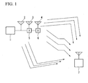
- FIG.1 is an illustration for explaining the method for transmitting signals from a radio transmitter of a first embodiment of the present invention to a radio receiver.
- Signals transmitted by the radio transmitter 1 reach the radio receiver 7 via multiple propagation paths.
- the radio transmitter 1 has a plurality of transmission antennas 2 to 4.
- a delay section 5 imparts a delay time T to signals transmitted by the transmission antenna 3 in comparison with signals transmitted by the transmission antenna 2.
- delay sections 5 and 6 impart a delay time 2T to signals transmitted by the transmission antenna 4.
- the radio receiver 7 receives signals transmitted from the radio transmitter 1.
- FIG. 1 an example in which the transmitter 1 has three transmission antennas 2 to 4 is described; but the number of transmission antenna is not necessarily limited to this number.
- the transmission antennas described above are transmission antennas, which are installed in a radio transmitter facilitated in a base station for cellular phones; hence, they can be realized using transmission antennas adapted for the same sector, different sectors of the same base station, and different base stations respectively.
- the following description is given with respect to transmission antennas adapted for the same sector, for example.
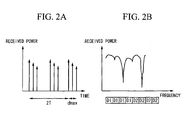
- FIGS. 2A and 2B are graphs showing a delay profile and a transfer function with respect to signals that reach a radio receiver via multiple (three) propagation paths having different delay times.
- FIG. 2A shows the delay profile representing that transmission signals reach the radio receiver via multiple propagation paths having different delay times with respect to time (horizontal axis) and received power (vertical axis). It shows that an instantaneous maximum delay time for the delay profile is 2T+dmax; hence, maximum delay waves are very high in comparison with ones that occur when each transmission antenna transmits the same signal.
- 2T represents a delay time difference between a signal, which reaches a reception antenna first, and a signal, which reaches the reception antenna lately, within radio waves generated by multiple transmission antennas.
- dmax represents an incoming time difference between a very fast propagation path, via which radio waves of the same transmission reach the reception antenna, and a very slow propagation path.
- FIG. 2B shows the transfer function that is produced by performing frequency conversion of the delay profile of FIG. 2A with respect to frequency (horizontal axis) and received power (vertical axis).
- an event in which the maximum delay time 2T+dmax is long indicates that frequency variations are rapid in the transfer function. Therefore, as shown in FIG. 2B , data D1 and D2 spread with a spreading factor 4 and are assigned with sub-carriers.
- the radio transmitter 1 it is preferable for the radio transmitter 1 to control the spreading factor or the coding rate of error correction coding in response to frequency variations of the transfer function.
- the delay time 2T is known in the radio transmitter 1, it is possible to determine the spreading factor or the coding rate of error correction coding irrespective of frequency variations of propagation paths.
- the instantaneous maximum delay time 2T+dmax of the delay profile be not overly long.
- FIGS. 3A, 3B, and 3C are graphs showing the delay profile and transfer functions with respect to signals that reach the radio receiver via multiple propagation paths having different delay times.
- FIG. 3A shows the delay profile in which transmission signals reach radio receivers via multiple (three) propagation paths having different delay times with respect to time (horizontal axis) and received power (vertical axis).
- FIG. 3B shows the transfer function regarding the radio receiver used by a user u1.
- FIG. 3C shows the transfer function regarding the radio receiver used by a user u2. Since the radio receivers of the users u1 and u2 are located at different positions, the transfer functions thereof differ instantaneously.
- the radio transmitter transmits data D1 to D4 via the frequency channel b2 with respect to the user u1.
- the radio transmitter transmits data D1 to D4 via the frequency channel b1 with respect to the user u2.
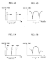
- FIGS. 4A and 4B and FIGS. 5A and 5B are graphs showing the relationship between a maximum delay time (n-1)T and frequency variations.
- n-1T a maximum delay time
- the maximum delay time (n-1)T between transmission antennas is set in a range of (n-1)T>1/Fc where Fc denotes the frequency bandwidth of a chunk, which is a basic region that is defined with respect to the frequency axis and time axis and that is secured when the user perform communication; thus, it is possible to create an environment easily achieving frequency diversity effects.
- the maximum delay time (n-1)T between transmission antennas is set in a range of (n-1)T ⁇ 1/Fc where Fc denotes the frequency bandwidth of a chunk; thus it is possible to create an environment easily achieving multiuser diversity effects.
- the delay time imparted to each transmission antenna is expressed as n-1 times longer than the delay time T, wherein T remains constant, whereas T can be varied in connection with each transmission antenna.
- (n-1)T ⁇ 1/Fc it is possible to reduce the number of transmission antennas for use in transmission of signals, thus reducing the maximum delay time.
- FIGS. 6A to 6C are illustrations for explaining that a radio transmitter 8 transmits the same signal to radio receivers via multiple transmission antennas without imparting delay times thereto.
- the radio transmitter 8 is equipped with multiple (three) transmission antennas, which are disposed in parallel with each other and which do not have directivity in a horizontal direction, wherein lobes e11 and e12 encompassed by ellipses occur as shown in FIG. 6A ; this causes a direction (see FIG. 6B ), in which a radio receiver 9 receives signals at a high received power over all frequency bands, and a direction (see FIG. 6C ), in which a radio receiver 10 receives signals at a low received power over all frequency bands.
- FIGS. 7A to 7C are illustrations for explaining that the radio transmitter 8 transmits the same signal to radio receivers via multiple transmission antennas with different delay times.
- the radio transmitter 8 is equipped with multiple (three) transmission antennas, which are disposed in parallel with each other and which do not have directivity in the horizontal direction, wherein lobes e21 to e26 encompassed by ellipses occur in a narrow band as shown in FIG. 7A .
- FIG. 8 is a graph showing the configuration of a chunk K used in the present embodiment. It shows that the chunk K is composed of nineteen sub-carriers, which are disposed in a frequency axis direction (a horizontal axis direction), and four OFDM (Orthogonal Frequency Division Multiplexing) symbols, which are disposed in a time axis direction (a vertical axis).
- a common pilot channel lies in regions r1 to r10 as shown in the figure, wherein it is used for estimating a propagation path and for measuring quality of received signals in decoding of a radio receiver.
- FIG. 9 is a plan view showing an example of the positioning relationship between a base station 11 and multiple terminals.
- Terminals 12, 13, and 14 serving as radio receivers are positioned in the periphery of the base station 11 serving as a radio transmitter, wherein they perform communications with the base station 11.
- the base station 11 is composed of three sectors SC1 to SC3, each of which is equipped with multiple (e.g., three) transmission antennas. That is, the three terminals 12 to 14 perform communications with the prescribed single sector SC1 in accordance with the method explained with FIG. 1 .
- Multiple transmission antennas can be realized using transmission antennas adapted to the same sector, different sectors of the same base station, different base stations; hence, multiple transmission antennas can be installed in different sectors of the same base station or in different base stations as described below.
- a graph of FIG. 10(a) shows a transfer function C11 monitored in the multiuser diversity region.
- a graph of FIG. 10(b) shows a transfer function C12 monitored in the frequency diversity region.
- the horizontal axis represents frequency
- the vertical axis represents received power.
- the graphs of FIG. 10(a) and (b) show the transfer functions C11 and C12 monitored by the terminal 12 of FIG. 9 .
- the frequency axis f crosses the received power axis at prescribed values of the received power.
- 10(c) is an illustration for explaining the method for performing communications by assigning the chunks K1 to K20, which are divided by way of the frequency axis (horizontal axis) direction and the time axis (vertical axis), to users.
- the chunks K1, K5, K9, K13, and K17 form a group L11.
- the chunks K2, K6, K10, K14, and K18 form a group L12.
- the chunks K3, K7, K11, K15, and K19 form a group L13.
- the chunks K4, K8, K12, K16, and 20 form a group L14.
- the groups L11 and L13 are set to the multiuser diversity region in advance, and the groups L12 and L14 are set to the frequency diversity region in advance. Therefore, the terminal calculates the transfer function of a propagation path by use of a common pilot channel of the chunks included in the group L11, thus monitoring a frequency band f1 with regard to the transfer function C11. Similarly, it calculates the transfer function of a propagation path by use of a common pilot channel of the chunks included in the group L 12, thus monitoring a frequency band f2 with regard to the transfer function C12. It calculates the transfer function of a propagation path by use of a common pilot channel of the chunks included in the group L 13.
- the situation in which the chunks K1 to K20 are divided into the groups L11 to L14 and are also assigned to the multiuser diversity region and the frequency diversity region respectively, is fixed and unchanged in the system design or can be dynamically changed in response to conditions of terminals (the number of terminals, the number of high-speed moving terminals, and the amount of information subjected to transmission).
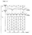
- a graph of FIG. 11(a) shows a transfer function C21 monitored in the multiuser diversity region.
- a graph of FIG. 11(b) shows a transfer function C22 monitored in the frequency diversity region.
- the horizontal axis represents frequency
- the vertical axis represents received power.
- the graphs of FIG. 10(a) and (b) show the transfer functions C21 and C22 monitored by the terminal 14 of FIG. 9 . They differ from the graphs of FIG. 10(a) and (b) with respect to the position of the terminal for monitoring propagation paths; hence, the transfer functions C21 and C22 are monitored differently than the transfer functions C11 and C 12 shown in the graphs of FIG. 10(a) and (b) .
- FIG. 11(c) is an illustration for explaining the method for performing communications by assigning the chunks K1 to K20, which are divided along the frequency axis (horizontal axis) direction and time axis (vertical axis), to users.
- the assignment of the chunks K1 to K20 into the groups L11 to L14 is similar to that shown in the graph of FIG 10(c) ; hence, the description thereof will be omitted.
- the terminal 14 calculates the transfer function of a propagation path by use of a common pilot channel of the chunks included in the group L1, thus monitoring the frequency band f1 with regard to the transfer function C21. It calculates the transfer function of a propagation path by use of a common pilot channel of the chunks included in the group L12, thus monitoring the frequency band f2 with regard to the transfer function C22. It calculates the transfer function of a propagation path by use of a common pilot channel of the chunks included in the group L 13, thus monitoring the frequency band f3 with regard to the transfer function C21.
- the terminal 12 calculates the transfer function of a propagation path by use of a common pilot channel of the chunks included in the group L14, thus monitoring the frequency band f4 with regard to the transfer function C22.
- CQI Channel Quality Indicator
- the terminal 12 performs comparison between the groups L11 and L13, i.e., it compares the frequency band f1 of the transfer function C11 and the frequency band f3 of the transfer function C11 in the quality of received signals in the base station, which thus assigns the group L11 (or the frequency band f1) to the terminal 12 so as to transmit signals.
- the terminal 14 performs comparison between the groups L11 and L13, i.e. it compares the frequency band f1 of the transfer function C21 and the frequency band f3 of the transfer function C21 in the quality of received signals in the base station, which thus assigns the group L13 (or the frequency band f3) to the terminal 14 so as to transmit signals.
- the frequency diversity region and the multiuser diversity region are determined in advance so as to apply different delay times to common pilot channels included therein, wherein scheduling is performed in accordance with the CQI information from the terminal, so that chunks are appropriately assigned to each terminal, thus producing adequate multiuser diversity effects.
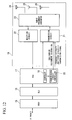
- FIG. 12 is a block diagram showing the constitution of a base station in accordance with a second embodiment of the present invention.
- the base station receives IP (Internet Protocol) packets and compresses their headers so as to transfer them to an RLC (Radio Link Control) section 16, wherein it has a PDCP (Packet Data Convergence Protocol) section 15 that restores headers so as to convert received data from the RLC section 16 into IP packets.
- IP Internet Protocol
- PDCP Packet Data Convergence Protocol
- MAC Media Access Control
- the MAC section 17 performs ARQ (Automatic Repeat Request) processing, scheduling processing, connection/disconnection of data, and control of a physical layer 18, wherein it transfers received data from the RLC section 16 to the physical layer 18, while it transfers transferred data from the physical layer 18 to the RLC section 16.
- the physical layer 18 converts transmission data from the MAC section 18 into radio transmission signals and transfers radio transmission signals to the MAC section 17 under the control of the MAC section 17.
- the MAC 17 has a scheduler 19 that determines assignment slots for performing communications with respect to each of terminals that perform communications with the base station. Specifically, the scheduler 19 assigns chunks, dependent upon communication times and communication frequencies, to radio receivers based on quality information (received power, received SINR, etc.) of received signals transmitted by radio receivers.
- a transmission circuit 21 of the physical layer 18 is controlled using sub-carrier assignment information based on chunk assignment information transmitted by the scheduler 19, wherein the MAC 17 has a transmission circuit controller 20 that controls the maximum delay time between transmission antennas in response to the frequency diversity region and the multiuser diversity region, which are described with reference to FIGS. 2 and 3 and FIGS. 10 and 11 , by use of frequency diversity/ multiuser diversity transmission signals.
- the frequency diversity region and the multiuser diversity region are divided on the frequency axis; but it is not necessarily limited to such a constitution.
- the transmission circuit controller 20 it is possible for the transmission circuit controller 20 to divide the frequency diversity region and the multiuser diversity region on the time axis.
- the physical layer 18 includes a reception circuit 22 that demodulates the output of a radio frequency converter 23 so as to transfer it to the MAC 17.
- the radio frequency converter 23 converts transmission signals from the transmission circuit 21 to suit radio frequencies, and it also converts received signals received by transmission antennas 24 to 26 to suit frequency bands executing processing of the reception circuit 22.
- it includes the transmission antennas 24 to 26 that transmit transmission signals from the radio frequency converter 23 to the radio space and that receives signals in the radio space.
- FIG. 13 is a flowchart showing the processing of the scheduler 19 ( FIG. 12 ).
- the scheduler 19 collects pieces of MCS (Modulation and Coding Scheme) information included in CQI from each terminal (step T2). Then, assignment of frequency channels is performed in order from a terminal having a high transfer speed of MCS in units of frequencies (step T3). Then, assignment of chunks is performed in order from a terminal having a high transfer speed of MCS in units of frequencies in response to its information value (step T4). Then, chunk assignment information obtained in the step T4 is supplied to the transmission circuit controller 20 (step T5).
- MCS Modulation and Coding Scheme
- step T7 When a transmission schedule is set to transmit the next transmission frame, the flow returns to the step T2, whereas when such a transmission schedule is not set, the flow proceeds to step T7 so as to end the processing (step T6). Thereafter, the processing of the scheduler 19 is ended (step T7).
- the terminal transmits the MCS information to the base station.
- the MCS information is quality information of received signals received by the terminal from the base station; hence, it is possible to use other information, which can define the quality of received signals such as average SINR (Signal to Interference and Noise Ratio), other than the MCS information representing the quality information of received signals.
- the transmission control circuit 20 which receives the chunk assignment information from the scheduler 19 in the step T5, controls the transmission circuit 20 in accordance with the chunk assignment information by use of the sub-carrier assignment information when transmitting the next transmission frame.
- FIG. 14 is a table showing an example of the MCS information used in the present embodiment.
- the MCS information (numbers 1 to 10) matches modulation systems (QPSK (Quadrature Phase Shift Keying) etc.) and error correction coding rates (1/8 etc.). That is, in connection with transfer speeds (1.942 Mbps etc.) shown in FIG. 14 , the MCS information indicates that the terminal requests communication whose transfer speed becomes higher as the number of the MCS information becomes large.
- QPSK Quadrature Phase Shift Keying
- FIG. 15 is a block diagram showing the constitution of the transmission circuit 21( FIG. 12 ) according to the present embodiment.
- the transmission circuit 21 includes user-dependent signal processors 31 a and 31 b for performing signal processing dependent upon users. It also includes a pilot signal generator 43 that generates pilot signals, which are used for estimation of propagation paths at terminals, so as to supply them to a sub-carrier assignment section 34.
- the sub-carrier assignment section 34 assigns the outputs of the user-dependent signal processors 31 a and 31b and the output of the pilot signal generator 43 to sub-carriers.
- antenna-dependent signal processors 41-1, 41-2, and 41-3 for performing signal processing dependent upon transmission antennas.
- the user-dependent signal processor 31 a includes an error correction coding section 32 for performing error correction coding on transmission data. It also includes a modulator 33 for performing modulation processing such as QPSK and 16QAM (Quadrature Amplitude Modulation) on the output of the error correction coding section.
- the outputs of the user-dependent signal processors 31a and 31 b are assigned with appropriate sub-carriers by the sub-carrier assignment section 34 based on the sub-carrier assignment information transmitted from the transmission circuit controller 20 ( FIG. 12 ); then, they are supplied to the antenna-dependent signal processors 41-1 to 41-3.
- the sub-carrier assignment section 34 assigns the output of the pilot signal generator 43 to the position of a common pilot signal (sub-carrier) shown in FIG. 8 .
- the antenna-dependent signal processor 41-1 includes a weighted multiplier 35 that inputs the output of the sub-carrier assignment section 34 and performs phase rotation ⁇ m or multiplication of a weight wm with respect to each sub-carrier so as to output it to an IFFT (Inverse Fast Fourier Transform) section 36. It also includes a parallel-to-serial converter 37 for performing parallel-to-serial conversion on the output of the IFFT section 36. In addition, it includes a GI addition section 38 for imparting a guard interval to the output of the parallel-to-serial converter 37. It further includes a filter 39 for extracting signals of a desired frequency band only from the output of the GI addition section 38.
- IFFT Inverse Fast Fourier Transform
- the antenna-dependent signal processors 41-2 and 41-3 have the same constitution as the antenna-dependent signal processor 41-1, wherein the outputs of the antenna-dependent signal processors 41-1, 41-2, and 41-3 are supplied to the transmission antennas 24, 25, and 26 ( FIG. 12 ) via the radio frequency converter 23 ( FIG. 12 ) for performing frequency conversion into radio frequencies, thus being transmitted as radio signals.
- Ts denotes a symbol length (time) of an OFDM symbol.
- (n-1)T denotes a circulating delay time applied to No. n transmission antenna in connection with No. 1 transmission antenna 1.
- a specific sub-carrier is used in a certain chunk. That is, it is used in either the frequency diversity region or the multiuser diversity region, wherein the transmission circuit controller 20 ( FIG. 20 ) for controlling the transmission circuit 20 transmits whether it is used in either the frequency diversity region or the multiuser diversity region by way of the frequency diversity/ multiuser diversity transmission signal, based on which the delay time T is changed.
- the weighted multiplier 35 multiplies the weight wm
- the weight is set as described below, thus making it possible to perform directivity control.
- an example of the weight wm is given by the following equation (1).
- wm is calculated in the form of vectors indicating weights used in the weighted multiplier 35, wherein the first term indicates a weight used by the first transmission antenna, the second term indicates a weight used by the second transmission antenna, ..., and the nth term indicates a weight used by the nth transmission antenna.
- ⁇ indicates a main beam direction
- k indicates a ratio between the frequency for transmitting signals and the frequency detected by way of the measurement of ⁇ .
- FIG. 15 is designed based on a design choice in which the number of users is two, and the number of transmission antennas is three; but a similar constitution can be realized based on other design choices.
- specific scramble codes which depend upon transmission antennas, sectors, and base stations, are applied to signals subjected to transmission via transmission antennas, there is a situation in which one transmission antenna may not simply delay signals of another transmission antenna; however, it is possible to apply the first and second embodiments to such a situation.
- specific codes are assigned to different transmission antennas in connection with the antenna-dependent signal processors 41-1, 41-2, and 41-3, specific codes are multiplied by sub-carriers by means of the sub-carrier assignment section 34 and the weighted multiplier 35 shown in FIG.
- FIG. 16 is an illustration for explaining the method for assigning chunks to terminals based on the information included in CQI from terminals.
- the following description is given with respect to the foregoing example shown in FIG. 9 in which the base station 11 performs communications with the terminals 12, 13, and 14.
- the terminal 12 transmits the MCS information (modulation methods requested by terminals and values representing coding rates ( FIG. 14 )) to the base station as the quality information of received signals representative of chunks included in the multiuser diversity region.
- a graph of FIG. 16(a) shows the transfer function C11 monitored in the multiuser diversity region.
- a graph of FIG. 16(b) shows the transfer function C12 monitored in the frequency diversity region. In the graphs of FIG.
- the horizontal axis represents frequency
- the vertical axis represents received power.
- the graphs of FIG. 16(a) and (b) show the transfer functions C11 and C12 monitored by the terminal 12 shown in FIG. 9 .
- the frequency axis f crosses the received power axis at prescribed values of received power.
- FIG. 16(c) shows the method for assigning the chunks K1 to K20, which are divided in the frequency axis (horizontal axis) direction and the time axis (vertical axis) direction, to users.
- the chunks K1, K5, K9, K13, and K17 form the group L11.
- the chunks K2, K6, K10, K14, and K18 form the group L12.
- the chunks K3, K7, K11, K15, and K19 form the group L13.
- the chunks K4, K8, K12, K16, and K20 form the group L 14.
- the groups L11 and L13 are set to the multiuser diversity region in advance, and the groups L12 and L14 are set to the frequency diversity region in advance.
- the terminal calculates the transfer function of a propagation path by use of a common pilot channel of a chunk included in the group L11, thus monitoring the frequency band f1 in the transfer function C 11.
- it calculates the transfer function of a propagation path by use of a common pilot signal of a chunk included in the group L12 so as to monitor the frequency band f2 in C12; and it calculates the transfer function of a propagation path by use of a common pilot channel of a chunk included in L 13 so as to monitor the frequency band f3 in the transfer function C11.
- it calculates the transfer function of a propagation path by use of a common pilot channel of a chunk included in the group L14 so as to monitor the frequency band f4 in the transfer function C12.
- the situation in which the chunks K1 to K20 are divided into the groups L11 to 114 and are assigned to the multiuser diversity region and the frequency diversity region respectively may be fixed without being changed in the system design; but it can be dynamically changed in response to the conditions of terminals (the number of terminals, the number of high-speed moving terminals, and the amount of information subjected to transmission).
- the present embodiment is designed such that the terminal 12 receives signals from the base station by use of the multiuser diversity region; hence, it transmits to the base station the quality information of received signals in the multiuser diversity region only by use of CQI.
- the MCS information modulation methods requested by terminals, and values of coding rates ( FIG.
- DCCCH Downlink Common Control Channel
- FIGS. 17 and 18 are illustrations for explaining that, in the situation shown in FIG. 9 , the terminals 13 and 14 sends the MCS information to the base station as the quality information of received signals of chunks included in the multiuser diversity region.
- the frequency axis f crosses the received power axis at prescribed values of received power.
- transfer functions C31 and C32 are shaped substantially similar to the transfer functions C11 and C12 shown in FIG.
- the base station 11 collects pieces of MCS information shown in FIGS. 16 , 17 , and 18 from the terminals 12, 13, and 14.
- FIG. 19 is a table explaining that, in the step T3 shown in FIG. 13 , the base station 11 assigns frequency channels to terminals in order from a terminal having a high transmission speed regarding the MCS information in units of frequencies (f1, f2, f3, and f4).
- the following description will be given with respect to the situation in which, in connection with the frequency band f1, the terminal 12 requests an average transmission speed of 8.2, the terminal 13 requests an average transmission speed of 4, and the terminal 14 requests an average transmission speed of 4.4.
- the frequency band f1 is assigned to the terminal 12 at priority 1, the terminal 14 at priority 2, and the terminal 13 at priority 3.
- the terminal requests an average transmission speed of 4.2
- the terminal 13 requests an average transmission speed of 1.8
- the terminal 14 requests an average transmission speed of 8.2 in connection with the frequency band f3.
- the frequency band f1 is assigned to the terminal 14 at priority 1, the terminal 12 at priority 2, and the terminal 13 at priority 3.
- FIG. 20 is a table for explaining that, in the step T4 shown in FIG. 13 , the base station 1 assigns chunks to terminals in a priority order shown in FIG. 19 from a terminal having a high priority and a large amount of MCS information.
- the chunk K1 dependent upon the frequency band f1 and the time domain t1 and the chunk K3 dependent upon the frequency band f3 and the time domain t1 are assigned to the terminals 12 and 14 both having priority 1 respectively.
- the terminal 13 whose MCS value is low and whose transmission speed is low is assigned with the chunk K5 dependent upon the frequency band f1 and the time domain t2, the chunk K7 dependent upon the frequency band f3 and the time domain t2, the chunk K9 dependent upon the frequency band f1 and the time domain t3, and the chunk K11 dependent upon the frequency band f3 and the time domain t3.
- the following description is given such that the same transmission speed is assigned to each terminal with respect to each single transmission frame; but this constitution is not a restriction.
- the following description is given such that the grouping in the steps T2 and T3, i.e. the grouping of terminals dependent upon the MCS information (see FIGS. 16 , 17 , and 18 ), is identical to the grouping in the step T4, i.e. the grouping, which is established when communication is performed in accordance with assignment of chunks determined in the step T4 (see FIG. 20 ); but this constitution is not a restriction.
- the base station 11 determines and assigns chunks to terminals in the step T4 shown in FIG. 13
- assignment of chunks to terminals is sent to the transmission circuit controller 20 in the step T5; hence, the transmission circuit controller 20 controls the transmission circuit 21 to realize this.
- the frequency diversity region and the multiuser diversity region are determined in advance, and different delay times are applied to common pilot channels included therein.
- the present embodiment is designed such that the terminals 12 and 14 select chunks having good reception qualities so as to perform communication; hence, it is possible to get high multiuser diversity effects.
- the terminal which performs communication using the frequency diversity region, sends the MCS information using the CQI information to the base station; hence, it is possible to use it for the basis of determination of the scheduling, modulation method, and coding rate of the terminal in downlink communication.
- the present invention will be described with respect to different grouping of chunks as shown in FIGS. 16 , 17 , and 18 .
- the constitution of the base station is shown in FIGS. 12 , 13 , and 15 in the second embodiment; hence, the description thereof is omitted in the present embodiment.
- chunks are assigned to terminals based on the information included in CQI from terminals.
- FIG. 9 the following description is given with respect to the situation in which communications are performed between the base station 11 and the terminals 12, 13, and 14.
- FIG. 21(a) shows the transfer function C11 monitored in the multiuser diversity region.
- FIG. 21(b) shows the transfer function C12 monitored in the frequency diversity region.
- the horizontal axis represents frequency
- the vertical axis represents received power.
- the frequency axis f crosses the received power axis at values of the received power.
- a table of FIG. 21(c) shows the method for performing communication by assigning the chunks K1 to K20 to users, wherein the horizontal axis represents frequency, and the vertical axis represents time.
- the chunks K1, K2, K3, and K4 form a group L21.
- the chunks K5, K6, K7, and K8 form a group L22.
- the chunks K9, K10, K11, and K12 form a group L23.
- the chunks K13, K14, K15, and K16 form a group L24.
- the chunks K17, K18, K19, and K20 form a group L25.
- the groups L21 and L23 are set to the multiuser diversity region in advance, and the groups L22, L24, and L25 are set to the frequency diversity region in advance. Therefore, when the terminal calculates the transfer function of a propagation path by use of a common pilot channel of the chunks included in the group L21, it is possible to monitor the frequency bands f1, f2, f3, and f4 with respect to the transfer function C11. In addition, when the terminal calculates the transfer function of a propagation path by use of a common pilot channel of the chunks included in the group L22, it is possible to monitor the frequency bands f1, f2, f3, and f4 with respect to the transfer function C 12.
- the situation in which the chunks K1 to K20 are divided into the groups L21 to L25 and are assigned to the multiuser diversity region and the frequency diversity region respectively is fixed without being changed in the system design or can be dynamically varied in response to conditions of terminals (the number of terminals, the number of high-speed moving terminals, and the amount of transferred information).
- FIG. 22 is an illustration explaining that the terminal 12 sends the MCS information to the base station as the quality information of received signals of chunks included in the multiuser diversity region in the situation shown in FIGS. 9 ad 21.
- a graph of FIG. 22(a) shows the transfer function C11 monitored in the multiuser diversity region.
- a graph of FIG. 22(b) shows the transfer function C 12 monitored in the frequency diversity region.
- the horizontal axis represents frequency
- the vertical axis represents received power.
- the graphs of FIG. 22(a) and (b) show the transfer functions C11 and C 12 that are monitored by the terminal 12 of FIG. 9 .
- FIG. 22(a) and (b) show the transfer functions C11 and C 12 that are monitored by the terminal 12 of FIG. 9 .
- FIG. 22(c) is table for explaining the method for performing communication by assigning the chunks K1 to K20 to users, wherein the horizontal axis represents frequency, and the vertical axis represents time.
- the chunks K1 to K20 are assigned to the groups L21 to L25, wherein the groups L21 and L23 are set to the multiuser diversity region in advance, and the groups L22, L24, and L25 are assigned to the frequency diversity region in advance.
- the terminal 12 serving as a radio receiver receives signals from the base station serving as a radio transmitter by use of the multiuser diversity region, so that it transmits to the base station only the quality information of received signals in the multiuser diversity region by use of CQI.
- the MCS information modulation methods requested by terminals, and values of coding rates ( FIG.
- Grouping of the groups L21 and L23 and the groups L22, L24, and L25 in connection with the frequency diversity region and the multiuser diversity region is included in a common control channel that is transmitted using the header of a transmission frame.
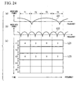
- FIGS. 23 and 24 are illustrations explaining the situation shown in FIG. 9 , in which the terminals 13 and 14 transmits to the base station the MCS information as the quality information of received signals of chunks included in the multiuser diversity region.
- the frequency axis f crosses the received power axis at prescribed values of the received power.
- transfer functions C31 and C32 are shaped substantially identical to the transfer functions C11 and C12 shown in FIG. 22 ; hence, compared to the group L23, the group L21 presents a larger amount of the MCS information so as to demonstrate good quality of received signals.
- the base station 11 collects pieces of the MCS information from the terminals 12, 13, and 14 as shown in FIGS. 22 , 23 , and 24 .
- FIG. 25 is a table explaining the method where the base station assigns frequency channels to terminals in order from a terminal having a high transfer speed of the MCS information in units of frequencies (f1, f2, f3, and f4) in the process of step T3 shown in FIG. 13 .
- the following description is given with respect to the situation in which the terminal 12 requests an average transmission speed of 8.5, the terminal 13 requests an average transmission speed of 4.5, and the terminal 14 requests an average transmission speed of 4 in the frequency band f1.
- priority 1 is assigned to the terminal 12
- priority 2 is assigned to the terminal 13
- priority 3 is assigned to the terminal 14.
- the terminal 12 requests an average transmission speed of 4
- the terminal 13 requests an average transmission speed of 1.5
- the terminal 14 requests an average transmission speed of 3 in the frequency band f2.
- priority 1 is assigned to the terminal 12
- priority 2 is assigned to the terminal 14, and priority 3 is assigned to the terminal 13.
- priority 1 is assigned to the terminal 14
- priority 2 is assigned to the terminal 12
- priority 3 is assigned to the terminal 13 in the frequency band f3.
- priority 1 is assigned to the terminal 12
- priority 2 is assigned to the terminal 13, and priority 3 is assigned to the terminal 14 in the frequency band f4.
- FIG. 26 is a table explaining that the base station assign chunks to terminals in order from a terminal whose priority is high and whose MCS information is large in accordance with the priorities shown in FIG. 25 .
- the terminal 12 and the terminal 14 both having priority 1 are assigned with the chunk K1 dependent upon the frequency band f1 and the time domain t1, the chunk K3 dependent upon the frequency band f3 and the time domain t1.
- the terminal 13 whose MCS value is low and whose transmission speed is low is assigned with the chunk K4 dependent upon the frequency band f4 and the time domain t1, the chunk K9 dependent upon the frequency band f1 and the time domain t3, and the chunk K12 dependent upon the frequency band f4 and the time domain t3.
- the aforementioned description is given with respect to the case in which the same data transmission speed is assigned to each terminal per each single transmission frame; but this case is not a restriction.
- Grouping is described with respect to the grouping in the step T2 and T3, i.e. the grouping dependent upon the MCS information determined by the terminal (see FIGS. 22 , 23 , and 24 ), and to the grouping in the step T4, i.e., the grouping that is established when performing communication in accordance with the chunk assignment determined by the step T4 (see FIG. 26 ); but this is not a restriction.
- the base station 11 selects chunks assigned to terminals in the step T4 of FIG. 13
- the assigned chunks of terminals are transmitted to the transmission circuit controller 20 in the step T5; hence, in order to achieve this, the transmission circuit controller 20 controls the transmission circuit 21.
- the present embodiment is designed such that the terminals 12 and 14 select chunks having good reception qualities so as to perform communication, thus achieving high multiuser diversity effects.
- the terminal which performs communication by use of the frequency diversity region, transmits to the base station the MCS information by use of CQI, which can be used for the determination of the scheduling and modulation method of the terminal and the coding rate in downlink communication.
- the present embodiment is described with respect to different groupings of chunks as shown in FIGS. 16 , 17 , and 18 .
- the constitution of the base station is already described in the second embodiment as shown in FIGS. 12 , 13 , and 15 ; hence, the description thereof is omitted in the present embodiment. Similar to the second embodiment, the following description is given with respect to the situation as shown in FIG. 9 in which communications are performed between the base station 11 serving as a radio transmitter and the terminals 12, 13, and 14 serving as radio receivers.
- a graph of FIG. 27(a) shows the transfer function C11 monitored in the multiuser diversity region.
- a graph of FIG. 27(b) shows the transfer function C12 monitored in the frequency diversity region.
- the horizontal axis represents frequency
- the vertical axis represents received power.
- the graphs of FIG. 27(a) and (b) show the transfer functions C11 and C 12 that are monitored by the terminal 12.
- the frequency axis f crosses the received power axis at prescribed values of the received power.
- 27(c) is a table for explaining the method for performing communication by assigning the chunks K1 to K20 to users, wherein the horizontal axis represents frequency, and the vertical axis represents time. It differs from FIG. 10 in terms of the grouping of the chunks K1 to K20. That is, the chunks K1, K2, K3, and K4 form the group L31. The chunks K5, K6, K9, and K10 form the group L32. The chunks K7, K8, K11, and K12 form the group L33. The chunks K13, K14, K17, and K18 form the group L34. The chunks K15, K16, K19, and K20 form the group L35.
- the groups L32 and L35 are set to the multiuser diversity region in advance, and the groups L31, L33, and L34 are set to the frequency diversity region in advance. Therefore, when the terminal calculates the transfer function of a propagation path by use of a common pilot channel of the chunks included in the group L31, it is possible to monitor the frequency bands f1, f2, f3, and f4 with respect to the transfer function C 12. When it calculates the transfer function of a propagation path by use of a common pilot channel of the chunks included in the group L32, it is possible to monitor the frequency bands f1 and f2 with respect to the transfer function C11.
- the situation in which the chunks K1 to K20 are divided into the groups L31 to L35 and are assigned to the multiuser diversity region and the frequency diversity region respectively is fixed without being changed in the system design or can be dynamically changed in response to conditions of terminals (the number of terminals, the number of high-speed moving terminals, and the amount of transferred information).
- the present embodiment employs different grouping of chunks as shown in FIG. 27 , wherein as similar to the second and third embodiments, the chunks K1 to K20 are divided into groups in advance and are assigned to the multiuser diversity region and the frequency diversity region respectively so that the transfer functions are monitored using common pilot channels included in groups so as to monitor qualities of received signals, based on which the base station performs scheduling so as to assign appropriate chunks to terminals, thus achieving adequate multiuser diversity effects.
- the first to fourth embodiments are described such that the groups included in the frequency diversity region and the multiuser diversity region are not changed, and the same grouping is applied to the next transmission frame (see FIG. 20 or FIG. 26 ) based on the information obtained by the steps T2 and T3 of FIG. 13 (see FIGS. 16 , 17 , and 18 or FIGS. 22 , 23 , and 24 ), then, the chunk assignment is performed in the step T4, whereas it is possible to change the grouping of chunks in the step T4 such that a different grouping is assigned to the next transmission frame. For example, it is possible to assign chunks to terminals in the step T4 in accordance with the grouping shown in FIG. 21 based on assignment results of terminals.
- FIG. 28 is a table for explaining chunks in the fourth embodiment.
- the terminals 12 and the terminal 14 both having priority 1 are assigned with the chunk K1 dependent upon the frequency band f1 and the time domain t 1 and the chunk K3 dependent upon the frequency band f3 and the time domain t1 respectively.
- the terminal 13 whose MCS value is low and whose transmission speed is low is assigned with the chunk K9 dependent upon the frequency band f1 and the time domain t3 and the chunk K11 dependent upon the frequency band f3 and the time domain t3.
- the base station applies different delay times to transmission antennas in connection with the frequency diversity region and the multiuser diversity region, scheduling is performed in accordance with the CQI information from terminals so that appropriate chunks are assigned to terminals so as to achieve adequate multiuser diversity effects since the frequency diversity region and the multiuser diversity region are determined in advance, and different delay times are applied to common pilot channels included therein.
- the terminal measures the quality of received signals so as to obtain the CQI information
- the base station performs scheduling so as to perform transmission
- the frequency diversity region and the multiuser diversity region can be composed of different chunks.
- the present embodiment is designed such that the terminals 12 and 14 select chunks having good reception qualities so as to perform communication, thus achieving high multiuser diversity effects.
- Common pilot channels DCPCH correspond to common pilot channels in the W-CDMA (Wideband Code Division Multiple Access) system, wherein they are used for estimation of conditions of downlink propagation paths, cell searches, and measurement of losses of propagation paths in uplink transmission power control.
- W-CDMA Wideband Code Division Multiple Access
- Dedicated pilot channels DDCH are transmitted to individual mobile stations via transmission antennas whose propagation paths (directivities) differ from those of cell shared antennas such as adaptive array antennas, wherein they can be used for the purpose of reinforcing downlink common pilot channels DCPCH in mobile stations having low reception qualities.
- Downlink synchronization channels DSCH correspond to synchronization channels SCH of the W-CDMA system, wherein they are used for cell searches of mobile stations, radio frames of OFDM signals, time slots, transmission timing intervals TTI (Transmission Timing Interval), and synchronization of OFDM symbol timing.
- Common control channels DCCCH include pieces of common control information such as broadcast information (corresponding to broadcast channels) corresponding to first common control physical channels P-CCPCH, second common control physical channels S-CCPCH, and paging indicator channels PICH in the W-CDMA system, packet paging indicator PI information (corresponding to paging indicator channels PICH) indicating existence of packet calls, packet paging information corresponding to packet calls (corresponding to paging channels PCH), and downlink access information (corresponding to downlink access channels FACH).
- broadcast information corresponding to broadcast channels
- P-CCPCH second common control physical channels S-CCPCH
- paging indicator channels PICH in the W-CDMA system
- packet paging indicator PI information corresponding to paging indicator channels PICH
- packet paging information corresponding to packet calls corresponding to paging channels PCH
- downlink access information corresponding to downlink access channels FACH.
- Shared control signaling channels DSCSCH correspond to shared control channels HS-SCCH regarding HS-DSCH included in high-speed physical downlink shared channels HS-PDSCH of the HSDPA (High Speed Downlink Packet Access) system, downlink dedicated control channels DPCCH, and acquired indicators AICH, wherein they are shared by multiple mobile stations and are used for transmission of information (modulation methods, spread coding, etc.) required for demodulation of high-speed downlink shared channels HS-DSCH in each mobile station, information required for error connection decoding and HARQ process, and scheduling information of radio resource (frequency, time).
- HSDPA High Speed Downlink Packet Access
- Downlink shared data channels DSDCH correspond to high-speed downlink shared channels HS-DSCH included in high-speed physical downlink shared channels HS-PDSCH of the HSDPA system and downlink dedicated data channels DPDCH, wherein they are used for transmission of packet data from the upper layer to the mobile station.
- Multicast/broadcast channels are used for transmission of information signals.
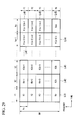
- FIG. 29 is an illustration showing the configuration of a transmission frame equivalent to that of FIG. 10 in consideration of each physical channel and the configuration of a transmission frame.
- the vertical axis represents frequency
- the horizontal axis represents time
- “a" transmission times t1 to ta are set to the horizontal axis
- "b" transmission frequencies are set to the vertical axis.
- the transmission frame is configured by axb chunks K1 to Kab.
- BW denotes a transmission frequency bandwidth used for the transmission of a transmission frame
- Fc denotes a frequency bandwidth of a chunk.
- FIG. 30 is an illustration showing an example of assignment for assigning each physical channel to each chunk in the configuration of a transmission frame shown in FIG. 29 .
- a common pilot channel is assigned to the headers of the chunks K1 to Kab (first OFDM symbols in time).
- Common control channels and downlink synchronization channels are transmitted using a part of the chunks included in the transmission time t1 and using the transmission frequency bandwidth BW.
- a common control channel is assigned to each chunk, wherein three terminals UE1 to UE3 are assigned as the common data channel, wherein, for example, the terminal UE1 is assigned to the chunks K1 and Kb+2, and wherein it shows that the chunks K2b+1 to K3b are coupled and transmitted using a single assignment slot S101 within three slots dividing the transmission time t3; it shows that the chunks K(a-2)b+1 to K(a-2)b+2 are coupled and transmitted using a single assignment slot S102 within three slots dividing the transmission time ta-1; and it shows that the chunks K(a-1)b+1, K(a-1)b+3, ..., and Kab lying in the frequency axis are alternately coupled and transmitted using a single assignment slot S 103 within three slots dividing the transmission time ta.
- the chunks K1 to Kb forming the group L41 are used in the frequency diversity region, it is possible to get frequency diversity effects as shown in FIG. 30 with respect to common control channels included in the group L41, common control signaling channels, downlink synchronization channels, and common data channels addressing the terminals UE1, UE2, and UE3 assigned to the chunks K1, K2, and K3.
- the chunks Kb+1 to K2b forming the group L42 are used in the multiuser diversity region, it is possible to get multiuser diversity effects in common control signaling channels and common data channels addressing the terminals UE3 and UE1 assigned to the chunks Kb+1 and Kb+2 by use of the methods described in the first to third embodiments.
- Computer-readable storage media mention flexible disks, magneto-optical disks, ROM, portable media such as CD-ROM, and storage devices such as hard disks incorporated in the computer system.
- computer-readable storage media embrace communication lines, which dynamically retain programs in short time periods when programs are transmitted via networks such as the Internet and via communication lines such as telephone lines, as well as volatile memories of the computer system serving as the server and client, which retain programs at certain times.
- the aforementioned programs can be realized using a part of the aforementioned functions, or they can be realized by combining the aforementioned functions with programs pre-stored in the computer system.
- the present invention is applicable to radio transmitters, radio communication systems, and radio transmission systems for transmitting signals to radio receivers via multiple transmission antennas, wherein by assigning communication times or communication frequencies to radio receivers based on the quality information of received signals transmitted by the radio receivers, it is possible to get very high multiuser diversity effects and to improve communication quality.
Landscapes
- Engineering & Computer Science (AREA)
- Signal Processing (AREA)
- Computer Networks & Wireless Communication (AREA)
- Mobile Radio Communication Systems (AREA)
- Radio Transmission System (AREA)
- Time-Division Multiplex Systems (AREA)
Abstract
Description
- The present invention relates to radio transmitters, radio communication systems, and radio transmission methods and in particular to transmitters and transmission methods for transmitting signals to radio receivers via multiple transmission antennas.
The present application claims priority on Japanese Patent Application No.2005-317266 filed in Japan on October 31, 2005 - Recently, in multicarrier transmission systems, user scheduling methods for arranging multiple blocks along frequency axes and time axes have been provided. Regions that are secured when users perform communications and that are defined by frequency axes and time axes are referred to as assignment slots, and blocks forming the basis of assignment blocks, i.e. regions defined by prescribed frequency bands and prescribed time domains, are referred to as chunks.
In this connection, in transmission via broadcast/multicast channels and control channels, blocks that are broadened in frequency axes are assigned so as to get frequency diversity effects, thus making it difficult to cause errors in received signals even when received power is low; and in transmission of unicast signals via one-to-one communications between radio transmitters and radio receivers, blocks that are broadened in frequency axes are assigned so as to get multiuser diversity effects. -
FIGS. 31 and 32 are drawings showing the relationships of signals, which are transmitted from radio transmitters to radio receivers, with reference to time (vertical axis) and frequency (horizontal axis). Transmission times t1 to t5 are set to the time axis. The transmission times t1 to t5 are identical to each other in time length. In addition, transmission frequencies f1 to f4 are set to the frequency axis. All the transmission frequencies f1 to f4 have the same frequency band of Fc. Thus, twenty chunks K1 to K20 are set by way of the transmission times t1 to t5 and the transmission frequencies f1 to f4.
By use of the chunks K1 to K20 shown inFIG. 31 , as shown inFIG. 31 , for example, four chunks K1 to K4 are coupled in the frequency axis and are equally divided into three regions along the time axis, thus setting communication slots S1 to S3, each of which has a time length of t1/3 and a frequency band of 4×f1 The assignment slot S1 is assigned to a first user; the assignment slot S2 is assigned to a second user; and the assignment slot S3 is assigned to a third user. Thus, it is possible for the first to third users to obtain frequency diversity effects. - The chunk K5 is assigned to a fourth user as an assignment slot S4. The chunks K6 and K7 are coupled to form an assignment slot S5, which is assigned to a fifth user. The chunk K8 is assigned to a sixth user as a slot S6. Thus, it is possible for the fourth to sixth users to obtain multiuser diversity effects.
The chunks K9 and K11 are coupled to form an assignment slot S7, which is assigned to a seventh user. The chunks K10 and K12 are coupled and then equally divided into three regions so as to set communication slots S8 to S10, each of which has a time length of t3/3 and a frequency band of 2×f2. The assignment slot S8 is assigned to an eighth user; the assignment slot S9 is assigned to a ninth user; and theassignment slot S 10 is assigned to a tenth user. Thus, it is possible for the seventh to tenth users to obtain frequency diversity effects. - The chunk K13 is assigned to an eleventh user as an assignment slot S11. The chunk K14 is assigned to a twelfth user as an assignment slot S12. The chunks K15 and K16 are coupled so as to form an assignment slot S13, which is assigned to a thirteenth user. Thus, it is possible for the eleventh to thirteenth users to obtain multiuser diversity effects.
In addition, the chunks K17 and K19 are coupled so as to form an assignment slot S14, which is assigned to a fourteenth user. The chunks K18 and K20 are coupled and then equally divided into three regions so as to form communication slots S15 toS 17, each of which has a time length of t5/3 and a frequency band of 2×f2.
The assignment slot S15 is assigned to a fifteenth user; the assignment slot S16 is assigned to a sixteenth user; and the assignment slot S17 is assigned to a seventeenth user. Thus, it is possible for the fourteenth to seventeenth users to obtain frequency diversity effects. - Non-Patent Document 1: 3GPP document, R1-050249, "Downlink Multiple Access Scheme for Evolved UTRA", [retrieved on August 17, 2005], Internet (URL: fip://fip.3gpp.org/TSG_RAN/WG1_RL1/TSGR1_40bis/Docs/R1-050249.zip)
- Non-Patent Document 2: 3GPP document, R1-050590, "Physical Channel and Multiplexing in Evolved UTRA Downlink", [retrieved on August 17, 2005], Internet (URL: ftp://ftp.3gpp.org/TSG_RAN/WG1_RL1/R1_Ad_Hocs/LTE_AH_June-05/Docs/R1-050590.zip)
- The conventionally-known technology simply performs frequency diversity and multiuser diversity on signals transmitted via a single transmission antenna, thus transmitting signals to a radio receiver. That is, it cannot further improve communication quality by combining the diversities with a transmission diversity using multiple antennas.
- The present invention is made in consideration of the aforementioned circumstances; and it is an object of the present invention to provide a radio transmitter, a radio communication system, and a radio transmission method, which can further improve communication quality with a radio transmitter by use of multiple transmission antennas.
- A radio transmitter of the present invention is provided to solve the aforementioned problem, wherein it has a scheduler for assigning a communication time and a communication frequency to each radio receiver based on quality information of received signals communicated by a radio receiver, a transmission circuit controller for transmitting whether a frequency diversity region or a multiuser diversity region is selected in each chunk, and a transmission circuit for applying different delay times to signals of multiple transmission antennas based on a transmission result of the transmission control circuit.
- The transmission circuit of the radio transmitter of the present invention sets different maximum delay times for transmission antennas in connection with the frequency diversity region and the multiuser diversity region.
- The transmission circuit of the radio transmitter of the present invention set the maximum delay times of the multiple transmission antennas to be larger than 1/Fc in the frequency diversity region and to be smaller than 1/Fc in the multiuser diversity region.
- The transmission circuit of the radio transmitter of the present invention applies the same delay time to each transmission antenna with respect to at least a common pilot signal included in the common chunk via a downlink common data channel.
- The transmission circuit controller of the radio transmitter of the present invention divides the frequency diversity region and the multiuser diversity region on the frequency axis.
- The transmission circuit controller of the radio transmitter of the present invention divides the frequency diversity region and the multiuser diversity region on the time axis.
- The transmission circuit controller of the radio transmitter of the present invention divides the frequency diversity region and the multiuser diversity region on both the frequency axis and the time axis.
- The scheduler of the radio transmitter of the present invention compares received signals of radio receivers in terms of quality information so as to determine the priority order, thus assigning chunks to radio receivers based on the determination result.
- The transmission circuit controller of the radio transmitter of the present invention controls the transmission circuit such that a chunk included in the frequency diversity region matches a chunk included in the multiuser diversity region when the priority order is determined by comparing received signals of radio receivers in terms of quality information, and a chunk included in the frequency diversity region matches a chunk included in the multiuser diversity region when chunks are assigned to radio receivers based on the priority order.
- In addition, the transmission circuit controller of the radio transmitter of the present invention controls the transmission circuit such that a chunk included in the frequency diversity region differs from a chunk included in the multiuser diversity region when the priority order is determined by comparing received signals of radio receivers in terms of quality information, and a chunk included in the frequency diversity region differs from a chunk included in the multiuser diversity region when chunks are assigned to radio receivers based on the priority order.
- The radio transmitter of the present invention applies different delay times to regions defined by time and frequency.
- The radio transmitter of the present invention applies different delay times to signals transmitted via multiple transmission antennas.
- The radio transmitter of the present invention is a radio transmitter that assigns transmission signals to regions defined by time and frequency, wherein the same delay time is periodically applied to regions along the time axis.
- The radio transmitter of the present invention is a radio transmitter that assigns transmission signals to regions defined by time and frequency, wherein the same delay time is periodically applied to regions along the frequency axis.
- The radio transmitter of the present invention has a scheduler for assigning regions defined by time and frequency to radio receivers based on quality information regarding received signals of radio receivers.
- The radio communication system of the present invention is constituted of a base station having the radio transmitter and a terminal that receives transmission signals transmitted from the base station so as to transmit the quality information of received signals to the base station.
- The radio transmission method of the present invention assigns communication times and communication frequencies to radio receivers based on quality information regarding received signals of radio receivers; it transmits whether each chunk is set to the frequency diversity region or the multiuser diversity region; and it applies different delay times to signals of multiple transmission antennas based on the transmission result.
- In the present invention, based on the quality information regarding received signals of radio receivers, the scheduler assigns communication times or communication frequencies to radio receivers; the transmission circuit controller transmits whether each chunk is set to the frequency diversity region or the multiuser diversity region; and the transmission circuit applies different delay times to signals of multiple transmission antennas based on the transmission result of the transmission circuit controller.
Thus, by assigning communication times or communication frequencies to radio receivers based on quality information regarding received signals of radio receivers, it is possible to get very high multiuser diversity effects, thus improving communication quality. -
- [
FIG. 1 ] An illustration showing that signals are transmitted from a radio transmitter of a first embodiment to a radio receiver. - [
FIG. 2A ] A delay profile showing that transmission signals are transmitted to a radio receiver via multiple propagation paths having different delay times in terms of time (horizontal axis) and received power (vertical axis). - [
FIG. 2B ] A graph showing a transfer function, which is produced by performing frequency conversion on the delay profile ofFIG. 2A , in terms of frequency (horizontal axis) and received power (vertical axis). - [
FIG. 3A ] A graph showing a delay profile, which indicates that transmission signals are transmitted to a radio receiver via multiple (three) propagation paths having different delay times, in terms of time (horizontal axis) and received power (vertical axis). - [
FIG. 3B ] A graph showing a transfer function of a radio receiver used by a user u1. - [
FIG. 3C ] A graph showing a transfer function of a radio receiver used by a user u2. - [
FIG. 4A ] A graph showing the relationship between time and received power. - [
FIG. 4B ] A graph showing the relationship between frequency and received power. - [
FIG. 5A ] A graph showing the relationship between time and received power. - [
FIG. 5B ] A graph showing the relationship between frequency and received power. - [
FIG. 6A ] An explanatory illustration showing that the same signal is transmitted without being applied with delays from multiple antennas of the first embodiment. - [
FIG. 6B ] A graph showing the relationship between frequency and received power with respect to received signals of aradio receiver 9. - [
FIG. 6C ] A graph showing the relationship between frequency and received power with respect to received signals of aradio receiver 10. - [
FIG. 7A ] An explanatory illustration showing that the same signal applied with different delays is transmitted via multiple antennas of the first embodiment. - [
FIG. 7B ] A graph showing the relationship between frequency and received power with respect to received signals of theradio receiver 9. - [
FIG. 7C ] A graph showing the relationship between frequency and received power with respect to received signals of theradio receiver 10. - [
FIG. 8 ] An illustration showing signal configurations of chunks in the first embodiment. - [
FIG. 9 ] An illustration showing the arrangement of a base station and a terminal in the first embodiment. - [
FIG. 10 ] An illustration for explaining grouping of chunks and propagation paths monitored by a terminal 12 in the first embodiment. - [
FIG. 11 ] An illustration for explaining grouping of chunks and propagation paths monitored by a terminal 14 in the first embodiment. - [
FIG. 12 ] A diagram showing the constitution of a base station in a second embodiment. - [
FIG. 13 ] A flowchart showing the operation of ascheduler 19 in the second embodiment. - [
FIG. 14 ] A table for explaining MCS information in the second embodiment. - [
FIG. 15 ] A diagram for explaining atransmission circuit 21 in the second embodiment. - [
FIG. 16 ] An illustration for explaining propagation paths monitored by a terminal 12 in the second embodiment and MCS information that is sent to the base station from the terminal 12. - [
FIG. 17 ] An illustration for explaining propagation paths monitored by a terminal 13 in the second embodiment and MCS information that is sent to the base station from the terminal 13. - [
FIG. 18 ] An illustration for explaining propagation paths monitored by a terminal 14 in the second embodiment and MCS information that is sent to the base station from the terminal 14. - [
FIG. 19 ] A table for explaining the operation of ascheduler 19 in the second embodiment. - [
FIG. 20 ] A table for explaining the operation of thescheduler 19 in the second embodiment. - [
FIG. 21 ] An illustration for explaining propagation paths monitored by a terminal 12 in a third embodiment and MCS information that is sent to the base station from the terminal 12. - [
FIG. 22 ] An illustration for explaining the propagation paths monitored by a terminal 13 in the third embodiment and MCS information that is transmitted from the terminal 13 to the base station. - [
FIG. 23 ] An illustration for explaining the propagation paths monitored by a terminal 14 in the third embodiment and MCS information that is transmitted from the terminal 14 to the base station. - [
FIG 24 ] An illustration for explaining the operation of thescheduler 19 in the third embodiment. - [
FIG. 25 ] A table for explaining the operation of thescheduler 19 in the third embodiment. - [
FIG. 26 ] A table for explaining the operation of thescheduler 19 in the third embodiment. - [
FIG. 27 ] An illustration for explaining grouping of chunks and propagation paths monitored by the terminal 12 in a fourth embodiment. - [
FIG. 28 ] A table for explaining the operation of thescheduler 19 in the fourth embodiment. - [
FIG. 29 ] An illustration for explaining chunks in the fourth embodiment. - [
FIG. 30 ] An illustration for explaining the arrangements of assignment slots and physical channels in the fourth embodiment. - [
FIG. 31 ] An illustration showing chunks regarding signals that are transmitted from a conventionally-known radio transmitter to a radio receiver. - [
FIG. 32 ] An illustration showing assignment slots regarding signals that are transmitted from the conventionally-known radio transmitter to the radio receiver. -
- 1
- radio receiver
- 2-4
- transmission antenna
- 5, 6
- delay
- 7
- radio receiver
- 8
- radio transmitter
- 9, 10
- radio receiver
- 11
- base station
- 12-14
- terminal
- 15
- PDCP
- 16
- RLC
- 17
- MAC
- 18
- physical layer
- 19
- scheduler
- 20
- transmission circuit controller
- 21
- transmission circuit
- 22
- reception circuit
- 23
- radio frequency converter
- 24-26
- transmission antenna
- 31 a, 31 b
- user-dependent signal processor
- 32
- error correction coding
- 33
- modulator
- 34
- sub-carrier assignment
- 35
- weighted multiplication
- 36
- IFFT
- 37
- parallel-to-series converter
- 38
- GI addition section
- 39
- filter
- 40
- D/A converter
- 41-1, 41-2, 41-3
- antenna-dependent signal processor
- 42
- weight calculation
- 43
- pilot signal generation
-
FIG.1 is an illustration for explaining the method for transmitting signals from a radio transmitter of a first embodiment of the present invention to a radio receiver. Signals transmitted by theradio transmitter 1 reach theradio receiver 7 via multiple propagation paths. Theradio transmitter 1 has a plurality oftransmission antennas 2 to 4.
Adelay section 5 imparts a delay time T to signals transmitted by thetransmission antenna 3 in comparison with signals transmitted by thetransmission antenna 2. In addition,delay sections delay time 2T to signals transmitted by thetransmission antenna 4.
Theradio receiver 7 receives signals transmitted from theradio transmitter 1. InFIG. 1 , an example in which thetransmitter 1 has threetransmission antennas 2 to 4 is described; but the number of transmission antenna is not necessarily limited to this number.
The transmission antennas described above are transmission antennas, which are installed in a radio transmitter facilitated in a base station for cellular phones; hence, they can be realized using transmission antennas adapted for the same sector, different sectors of the same base station, and different base stations respectively.
The following description is given with respect to transmission antennas adapted for the same sector, for example. -
FIGS. 2A and 2B are graphs showing a delay profile and a transfer function with respect to signals that reach a radio receiver via multiple (three) propagation paths having different delay times.FIG. 2A shows the delay profile representing that transmission signals reach the radio receiver via multiple propagation paths having different delay times with respect to time (horizontal axis) and received power (vertical axis). It shows that an instantaneous maximum delay time for the delay profile is 2T+dmax; hence, maximum delay waves are very high in comparison with ones that occur when each transmission antenna transmits the same signal. Herein, 2T represents a delay time difference between a signal, which reaches a reception antenna first, and a signal, which reaches the reception antenna lately, within radio waves generated by multiple transmission antennas. In addition, dmax represents an incoming time difference between a very fast propagation path, via which radio waves of the same transmission reach the reception antenna, and a very slow propagation path. -
FIG. 2B shows the transfer function that is produced by performing frequency conversion of the delay profile ofFIG. 2A with respect to frequency (horizontal axis) and received power (vertical axis). In the delay profile described above, an event in which themaximum delay time 2T+dmax is long indicates that frequency variations are rapid in the transfer function. Therefore, as shown inFIG. 2B , data D1 and D2 spread with a spreadingfactor 4 and are assigned with sub-carriers. In this connection, it is preferable for theradio transmitter 1 to control the spreading factor or the coding rate of error correction coding in response to frequency variations of the transfer function. In the aforementioned method, since thedelay time 2T is known in theradio transmitter 1, it is possible to determine the spreading factor or the coding rate of error correction coding irrespective of frequency variations of propagation paths.
On the other hand, in order to get multiuser diversity effects, it is preferable that the instantaneousmaximum delay time 2T+dmax of the delay profile be not overly long. -
FIGS. 3A, 3B, and 3C are graphs showing the delay profile and transfer functions with respect to signals that reach the radio receiver via multiple propagation paths having different delay times.FIG. 3A shows the delay profile in which transmission signals reach radio receivers via multiple (three) propagation paths having different delay times with respect to time (horizontal axis) and received power (vertical axis).
FIG. 3B shows the transfer function regarding the radio receiver used by a user u1.FIG. 3C shows the transfer function regarding the radio receiver used by a user u2. Since the radio receivers of the users u1 and u2 are located at different positions, the transfer functions thereof differ instantaneously.
When a low frequency range is connected to a frequency channel b1 and a high frequency range is connected to a frequency channel b2 in the frequencies shown inFIGS. 3B and 3C , the user u1 obtains a good quality in the frequency channel b2 but the user u2 obtains a good quality in the frequency channel b1. Therefore, the radio transmitter transmits data D1 to D4 via the frequency channel b2 with respect to the user u1. In addition, the radio transmitter transmits data D1 to D4 via the frequency channel b1 with respect to the user u2. - By use of instantaneous difference of qualities between frequency channels, it is possible to get multiuser diversity effects for improving the transmission efficiency by performing communications via different frequency channels by users.
However, when themaximum delay time 2T+dmax becomes very long, frequency variations of the transfer function become rapid so that the difference of qualities between the frequency channels b1 and b2 becomes small. Therefore, in order to get adequate multiuser diversity effects, it is important to reduce themaximum delay time 2T+dmax as shown inFIG. 3A . -
FIGS. 4A and 4B and FIGS. 5A and 5B are graphs showing the relationship between a maximum delay time (n-1)T and frequency variations. When an incoming time difference between two incoming waves w31 and w32 is (n-1)T as shown inFIG. 4A , the transfer function of this propagation path is as shown inFIG. 4B . That is, an interval of amplitude drops regarding the received power (vertical axis) is F=1/(n-1)T. - It is described above how frequency diversity effects and multiuser diversity effects differ in terms of frequency variations of transfer functions; hence, in order to get frequency diversity effects, the maximum delay time (n-1)T between transmission antennas is set in a range of (n-1)T>1/Fc where Fc denotes the frequency bandwidth of a chunk, which is a basic region that is defined with respect to the frequency axis and time axis and that is secured when the user perform communication; thus, it is possible to create an environment easily achieving frequency diversity effects.
On the other hand, in order to get multiuser diversity effects, the maximum delay time (n-1)T between transmission antennas is set in a range of (n-1)T<1/Fc
where Fc denotes the frequency bandwidth of a chunk; thus it is possible to create an environment easily achieving multiuser diversity effects. In the following description, the inequality of (n-1)T<1/Fc may embrace (n-1)T=0. In the following description, the delay time imparted to each transmission antenna is expressed as n-1 times longer than the delay time T, wherein T remains constant, whereas T can be varied in connection with each transmission antenna.
In order to get multiuser diversity effects, instead of setting (n-1)T<1/Fc, it is possible to reduce the number of transmission antennas for use in transmission of signals, thus reducing the maximum delay time. - As described above, in respect of transmission signals via the frequency diversity or the multiuser diversity ((n-1)T>1/Fc or (n-1)T<1/Fc), it is possible to get frequency diversity effects and multiuser diversity effects without being influenced by conditions of propagation paths.
In this connection, it is possible to switch over transmission of signals from the radio transmitter by way of the frequency diversity or the multiuser diversity in response to types of transmission signals (pilot signals, control signals, broadcast/multicast signals, etc.) and moving speeds of radio receivers (wherein the frequency diversity is selected in a high moving speed, while the multiuser diversity is selected in a low moving speed). -
FIGS. 6A to 6C are illustrations for explaining that aradio transmitter 8 transmits the same signal to radio receivers via multiple transmission antennas without imparting delay times thereto. As shown inFIG. 6A , theradio transmitter 8 is equipped with multiple (three) transmission antennas, which are disposed in parallel with each other and which do not have directivity in a horizontal direction, wherein lobes e11 and e12 encompassed by ellipses occur as shown inFIG. 6A ; this causes a direction (seeFIG. 6B ), in which aradio receiver 9 receives signals at a high received power over all frequency bands, and a direction (seeFIG. 6C ), in which aradio receiver 10 receives signals at a low received power over all frequency bands. -
FIGS. 7A to 7C are illustrations for explaining that theradio transmitter 8 transmits the same signal to radio receivers via multiple transmission antennas with different delay times. As shown inFIG. 7A , theradio transmitter 8 is equipped with multiple (three) transmission antennas, which are disposed in parallel with each other and which do not have directivity in the horizontal direction, wherein lobes e21 to e26 encompassed by ellipses occur in a narrow band as shown inFIG. 7A . This causes a frequency band achieving a high received power and a frequency band achieving a low received power with respect to received signals, and it is possible to maintain the average received power substantially constant irrespective of directions; hence, it is possible to achieve substantially the same quality with respect to both of the received power of signals in the radio receiver 9 (seeFIG. 7B ) and the received power of signals in the radio receiver 10 (seeFIG. 7C ). Therefore, the method, in which theradio transmitter 8 transmits signals via transmission antennas with different delay times, can compensate for the drawback explained withFIG. 6 , in which the same signal is transmitted via multiple transmission antennas. -
FIG. 8 is a graph showing the configuration of a chunk K used in the present embodiment. It shows that the chunk K is composed of nineteen sub-carriers, which are disposed in a frequency axis direction (a horizontal axis direction), and four OFDM (Orthogonal Frequency Division Multiplexing) symbols, which are disposed in a time axis direction (a vertical axis). A common pilot channel lies in regions r1 to r10 as shown in the figure, wherein it is used for estimating a propagation path and for measuring quality of received signals in decoding of a radio receiver. -
FIG. 9 is a plan view showing an example of the positioning relationship between abase station 11 and multiple terminals.Terminals base station 11 serving as a radio transmitter, wherein they perform communications with thebase station 11. Thebase station 11 is composed of three sectors SC1 to SC3, each of which is equipped with multiple (e.g., three) transmission antennas. That is, the threeterminals 12 to 14 perform communications with the prescribed single sector SC1 in accordance with the method explained withFIG. 1 .
Multiple transmission antennas can be realized using transmission antennas adapted to the same sector, different sectors of the same base station, different base stations; hence, multiple transmission antennas can be installed in different sectors of the same base station or in different base stations as described below. - A graph of
FIG. 10(a) shows a transfer function C11 monitored in the multiuser diversity region. A graph ofFIG. 10(b) shows a transfer function C12 monitored in the frequency diversity region. In graphs ofFIG. 10(a) and (b) , the horizontal axis represents frequency, and the vertical axis represents received power. The graphs ofFIG. 10(a) and (b) show the transfer functions C11 and C12 monitored by theterminal 12 ofFIG. 9 . In the graphs ofFIG. 10(a) and (b) , the frequency axis f crosses the received power axis at prescribed values of the received power.
FIG. 10(c) is an illustration for explaining the method for performing communications by assigning the chunks K1 to K20, which are divided by way of the frequency axis (horizontal axis) direction and the time axis (vertical axis), to users. In the illustration ofFIG. 10(c) , the chunks K1, K5, K9, K13, and K17 form a group L11. The chunks K2, K6, K10, K14, and K18 form a group L12. The chunks K3, K7, K11, K15, and K19 form a group L13. The chunks K4, K8, K12, K16, and 20 form a group L14. - The groups L11 and L13 are set to the multiuser diversity region in advance, and the groups L12 and L14 are set to the frequency diversity region in advance.
Therefore, the terminal calculates the transfer function of a propagation path by use of a common pilot channel of the chunks included in the group L11, thus monitoring a frequency band f1 with regard to the transfer function C11. Similarly, it calculates the transfer function of a propagation path by use of a common pilot channel of the chunks included in thegroup L 12, thus monitoring a frequency band f2 with regard to the transfer function C12. It calculates the transfer function of a propagation path by use of a common pilot channel of the chunks included in thegroup L 13. It calculates the transfer function of a propagation path by use of a common pilot channel of the chunks included in the group L14, thus monitoring a frequency band f4 with regard to the transfer function C12.
The situation, in which the chunks K1 to K20 are divided into the groups L11 to L14 and are also assigned to the multiuser diversity region and the frequency diversity region respectively, is fixed and unchanged in the system design or can be dynamically changed in response to conditions of terminals (the number of terminals, the number of high-speed moving terminals, and the amount of information subjected to transmission). - A graph of
FIG. 11(a) shows a transfer function C21 monitored in the multiuser diversity region. A graph ofFIG. 11(b) shows a transfer function C22 monitored in the frequency diversity region. In the graphs ofFIG. 11(a) and (b) , the horizontal axis represents frequency, and the vertical axis represents received power. The graphs ofFIG. 10(a) and (b) show the transfer functions C21 and C22 monitored by theterminal 14 ofFIG. 9 . They differ from the graphs ofFIG. 10(a) and (b) with respect to the position of the terminal for monitoring propagation paths; hence, the transfer functions C21 and C22 are monitored differently than the transfer functions C11 andC 12 shown in the graphs ofFIG. 10(a) and (b) . In the graphs ofFIG. 11(a) and (b) , the frequency axis f crosses the received power axis at prescribed values of the received power.
FIG. 11(c) is an illustration for explaining the method for performing communications by assigning the chunks K1 to K20, which are divided along the frequency axis (horizontal axis) direction and time axis (vertical axis), to users. The assignment of the chunks K1 to K20 into the groups L11 to L14 is similar to that shown in the graph ofFIG 10(c) ; hence, the description thereof will be omitted. - The terminal 14 (
FIG. 9 ) calculates the transfer function of a propagation path by use of a common pilot channel of the chunks included in the group L1, thus monitoring the frequency band f1 with regard to the transfer function C21. It calculates the transfer function of a propagation path by use of a common pilot channel of the chunks included in the group L12, thus monitoring the frequency band f2 with regard to the transfer function C22. It calculates the transfer function of a propagation path by use of a common pilot channel of the chunks included in thegroup L 13, thus monitoring the frequency band f3 with regard to the transfer function C21. It calculates the transfer function of a propagation path by use of a common pilot channel of the chunks included in the group L14, thus monitoring the frequency band f4 with regard to the transfer function C22.
When the quality of received signals of each chunk is transmitted as the information included in CQI (Channel Quality Indicator) that is transmitted to the base station via each channel, the terminal 12 (FIG. 9 ) performs comparison between the groups L11 and L13, i.e., it compares the frequency band f1 of the transfer function C11 and the frequency band f3 of the transfer function C11 in the quality of received signals in the base station, which thus assigns the group L11 (or the frequency band f1) to the terminal 12 so as to transmit signals. - Similarly, the terminal 14 (
FIG. 9 ) performs comparison between the groups L11 and L13, i.e. it compares the frequency band f1 of the transfer function C21 and the frequency band f3 of the transfer function C21 in the quality of received signals in the base station, which thus assigns the group L13 (or the frequency band f3) to the terminal 14 so as to transmit signals.
Thus, when the base station applies different delay times to transmission antennas in connection with the frequency diversity region and the multiuser diversity region, the frequency diversity region and the multiuser diversity region are determined in advance so as to apply different delay times to common pilot channels included therein, wherein scheduling is performed in accordance with the CQI information from the terminal, so that chunks are appropriately assigned to each terminal, thus producing adequate multiuser diversity effects. -
FIG. 12 is a block diagram showing the constitution of a base station in accordance with a second embodiment of the present invention.
The base station receives IP (Internet Protocol) packets and compresses their headers so as to transfer them to an RLC (Radio Link Control)section 16, wherein it has a PDCP (Packet Data Convergence Protocol)section 15 that restores headers so as to convert received data from theRLC section 16 into IP packets. In addition, it transfers received data from thePDCP section 15 to an MAC (Media Access Control)section 17, while it transfers data from theMAC section 17 to thePDCP section 15 by way of theRLC section 16.
TheMAC section 17 performs ARQ (Automatic Repeat Request) processing, scheduling processing, connection/disconnection of data, and control of aphysical layer 18, wherein it transfers received data from theRLC section 16 to thephysical layer 18, while it transfers transferred data from thephysical layer 18 to theRLC section 16. Thephysical layer 18 converts transmission data from theMAC section 18 into radio transmission signals and transfers radio transmission signals to theMAC section 17 under the control of theMAC section 17. - The
MAC 17 has ascheduler 19 that determines assignment slots for performing communications with respect to each of terminals that perform communications with the base station. Specifically, thescheduler 19 assigns chunks, dependent upon communication times and communication frequencies, to radio receivers based on quality information (received power, received SINR, etc.) of received signals transmitted by radio receivers.
Atransmission circuit 21 of thephysical layer 18 is controlled using sub-carrier assignment information based on chunk assignment information transmitted by thescheduler 19, wherein theMAC 17 has atransmission circuit controller 20 that controls the maximum delay time between transmission antennas in response to the frequency diversity region and the multiuser diversity region, which are described with reference toFIGS. 2 and3 andFIGS. 10 and11 , by use of frequency diversity/ multiuser diversity transmission signals.
The following description is given in such a way that the frequency diversity region and the multiuser diversity region are divided on the frequency axis; but it is not necessarily limited to such a constitution. For example, it is possible for thetransmission circuit controller 20 to divide the frequency diversity region and the multiuser diversity region on the time axis. - The
physical layer 18 includes areception circuit 22 that demodulates the output of aradio frequency converter 23 so as to transfer it to theMAC 17. Theradio frequency converter 23 converts transmission signals from thetransmission circuit 21 to suit radio frequencies, and it also converts received signals received bytransmission antennas 24 to 26 to suit frequency bands executing processing of thereception circuit 22. In addition, it includes thetransmission antennas 24 to 26 that transmit transmission signals from theradio frequency converter 23 to the radio space and that receives signals in the radio space. -
FIG. 13 is a flowchart showing the processing of the scheduler 19 (FIG. 12 ). First, thescheduler 19 collects pieces of MCS (Modulation and Coding Scheme) information included in CQI from each terminal (step T2). Then, assignment of frequency channels is performed in order from a terminal having a high transfer speed of MCS in units of frequencies (step T3). Then, assignment of chunks is performed in order from a terminal having a high transfer speed of MCS in units of frequencies in response to its information value (step T4). Then, chunk assignment information obtained in the step T4 is supplied to the transmission circuit controller 20 (step T5). When a transmission schedule is set to transmit the next transmission frame, the flow returns to the step T2, whereas when such a transmission schedule is not set, the flow proceeds to step T7 so as to end the processing (step T6). Thereafter, the processing of thescheduler 19 is ended (step T7). - The aforementioned description is given in such a way that the terminal transmits the MCS information to the base station. However, the MCS information is quality information of received signals received by the terminal from the base station; hence, it is possible to use other information, which can define the quality of received signals such as average SINR (Signal to Interference and Noise Ratio), other than the MCS information representing the quality information of received signals.
In addition, thetransmission control circuit 20, which receives the chunk assignment information from thescheduler 19 in the step T5, controls thetransmission circuit 20 in accordance with the chunk assignment information by use of the sub-carrier assignment information when transmitting the next transmission frame. -
FIG. 14 is a table showing an example of the MCS information used in the present embodiment. The MCS information (numbers 1 to 10) matches modulation systems (QPSK (Quadrature Phase Shift Keying) etc.) and error correction coding rates (1/8 etc.). That is, in connection with transfer speeds (1.942 Mbps etc.) shown inFIG. 14 , the MCS information indicates that the terminal requests communication whose transfer speed becomes higher as the number of the MCS information becomes large. -
FIG. 15 is a block diagram showing the constitution of the transmission circuit 21(FIG. 12 ) according to the present embodiment. Thetransmission circuit 21 includes user-dependent signal processors pilot signal generator 43 that generates pilot signals, which are used for estimation of propagation paths at terminals, so as to supply them to asub-carrier assignment section 34. Thesub-carrier assignment section 34 assigns the outputs of the user-dependent signal processors pilot signal generator 43 to sub-carriers. Furthermore, it includes antenna-dependent signal processors 41-1, 41-2, and 41-3 for performing signal processing dependent upon transmission antennas.
The user-dependent signal processor 31 a includes an errorcorrection coding section 32 for performing error correction coding on transmission data. It also includes amodulator 33 for performing modulation processing such as QPSK and 16QAM (Quadrature Amplitude Modulation) on the output of the error correction coding section.
The outputs of the user-dependent signal processors sub-carrier assignment section 34 based on the sub-carrier assignment information transmitted from the transmission circuit controller 20 (FIG. 12 ); then, they are supplied to the antenna-dependent signal processors 41-1 to 41-3. Thesub-carrier assignment section 34 assigns the output of thepilot signal generator 43 to the position of a common pilot signal (sub-carrier) shown inFIG. 8 . - The antenna-dependent signal processor 41-1 includes a
weighted multiplier 35 that inputs the output of thesub-carrier assignment section 34 and performs phase rotation θm or multiplication of a weight wm with respect to each sub-carrier so as to output it to an IFFT (Inverse Fast Fourier Transform)section 36. It also includes a parallel-to-serial converter 37 for performing parallel-to-serial conversion on the output of theIFFT section 36. In addition, it includes aGI addition section 38 for imparting a guard interval to the output of the parallel-to-serial converter 37. It further includes afilter 39 for extracting signals of a desired frequency band only from the output of theGI addition section 38. It further includes a D/A converter 40 for performing digital-to-analog conversion on the output of thefilter 39.
The antenna-dependent signal processors 41-2 and 41-3 have the same constitution as the antenna-dependent signal processor 41-1, wherein the outputs of the antenna-dependent signal processors 41-1, 41-2, and 41-3 are supplied to thetransmission antennas FIG. 12 ) via the radio frequency converter 23 (FIG. 12 ) for performing frequency conversion into radio frequencies, thus being transmitted as radio signals. - The phase rotation that is imparted by the
weighted multiplier 35 is represented as θm=2πfm·(n-1)T. Herein, fm denotes a frequency interval between No. 0 sub-carrier and No. m sub-carrier, wherein it is represented as fm=m/Ts. Ts denotes a symbol length (time) of an OFDM symbol. (n-1)T denotes a circulating delay time applied to No. n transmission antenna in connection with No. 1transmission antenna 1. A specific sub-carrier is used in a certain chunk. That is, it is used in either the frequency diversity region or the multiuser diversity region, wherein the transmission circuit controller 20 (FIG. 20 ) for controlling thetransmission circuit 20 transmits whether it is used in either the frequency diversity region or the multiuser diversity region by way of the frequency diversity/ multiuser diversity transmission signal, based on which the delay time T is changed. - When the
weighted multiplier 35 multiplies the weight wm, the weight is set as described below, thus making it possible to perform directivity control. Assuming a linear array of No. n transmission antenna in which a distance between components matches a half the wavelength of a carrier frequency, an example of the weight wm is given by the following equation (1). -

- In the above, wm is calculated in the form of vectors indicating weights used in the
weighted multiplier 35, wherein the first term indicates a weight used by the first transmission antenna, the second term indicates a weight used by the second transmission antenna, ..., and the nth term indicates a weight used by the nth transmission antenna.
In the aforementioned wm, n denotes the number of transmission antennas, where n=3 in the present embodiment, wherein θ indicates a main beam direction, and k indicates a ratio between the frequency for transmitting signals and the frequency detected by way of the measurement of θ.
As the main beam direction θ, a value, which is measured by a radio receiver or a counterpart terminal in communication, is transmitted to a weight calculation section 310 and is used in calculation of the weight wm. -
FIG. 15 is designed based on a design choice in which the number of users is two, and the number of transmission antennas is three; but a similar constitution can be realized based on other design choices. When specific scramble codes, which depend upon transmission antennas, sectors, and base stations, are applied to signals subjected to transmission via transmission antennas, there is a situation in which one transmission antenna may not simply delay signals of another transmission antenna; however, it is possible to apply the first and second embodiments to such a situation.
Specifically, when specific codes are assigned to different transmission antennas in connection with the antenna-dependent signal processors 41-1, 41-2, and 41-3, specific codes are multiplied by sub-carriers by means of thesub-carrier assignment section 34 and theweighted multiplier 35 shown inFIG. 15 and are then subjected to transmission in connection with different transmission antennas. When the antenna-dependent signal processors 41-1, 41-2, and 41-3 are assigned to different sectors, specific codes are multiplied by sub-carriers by means of thesub-carrier assignment section 34 and theweighted multiplier 35 shown inFIG. 15 and are then subjected to transmission in connection with different sectors. When the antenna-dependent signal processors 41-1, 41-2, and 41-3 are assigned to different base stations, specific codes are multiplied by sub-carriers by means of thesub-carrier assignment section 34 and theweighted multiplier 35 shown inFIG. 15 and are then subjected to transmission in connection with different base stations. -
FIG. 16 is an illustration for explaining the method for assigning chunks to terminals based on the information included in CQI from terminals. The following description is given with respect to the foregoing example shown inFIG. 9 in which thebase station 11 performs communications with theterminals FIG. 14 )) to the base station as the quality information of received signals representative of chunks included in the multiuser diversity region.
A graph ofFIG. 16(a) shows the transfer function C11 monitored in the multiuser diversity region. A graph ofFIG. 16(b) shows the transfer function C12 monitored in the frequency diversity region. In the graphs ofFIG. 16(a) and (b) , the horizontal axis represents frequency, and the vertical axis represents received power. The graphs ofFIG. 16(a) and (b) show the transfer functions C11 and C12 monitored by the terminal 12 shown inFIG. 9 . In the graphs ofFIG. 16(a) and (b) , the frequency axis f crosses the received power axis at prescribed values of received power. - An illustration of
FIG. 16(c) shows the method for assigning the chunks K1 to K20, which are divided in the frequency axis (horizontal axis) direction and the time axis (vertical axis) direction, to users. Herein, the chunks K1, K5, K9, K13, and K17 form the group L11. The chunks K2, K6, K10, K14, and K18 form the group L12. The chunks K3, K7, K11, K15, and K19 form the group L13. The chunks K4, K8, K12, K16, and K20 form thegroup L 14.
The groups L11 and L13 are set to the multiuser diversity region in advance, and the groups L12 and L14 are set to the frequency diversity region in advance.
The terminal calculates the transfer function of a propagation path by use of a common pilot channel of a chunk included in the group L11, thus monitoring the frequency band f1 in thetransfer function C 11. In addition, it calculates the transfer function of a propagation path by use of a common pilot signal of a chunk included in the group L12 so as to monitor the frequency band f2 in C12; and it calculates the transfer function of a propagation path by use of a common pilot channel of a chunk included inL 13 so as to monitor the frequency band f3 in the transfer function C11. Furthermore, it calculates the transfer function of a propagation path by use of a common pilot channel of a chunk included in the group L14 so as to monitor the frequency band f4 in the transfer function C12. - The situation in which the chunks K1 to K20 are divided into the groups L11 to 114 and are assigned to the multiuser diversity region and the frequency diversity region respectively may be fixed without being changed in the system design; but it can be dynamically changed in response to the conditions of terminals (the number of terminals, the number of high-speed moving terminals, and the amount of information subjected to transmission).
The present embodiment is designed such that the terminal 12 receives signals from the base station by use of the multiuser diversity region; hence, it transmits to the base station the quality information of received signals in the multiuser diversity region only by use of CQI. As shown inFIG. 16(c) , the MCS information (modulation methods requested by terminals, and values of coding rates (FIG. 14 )) is sent to the base station as the quality information of received signals of chunks included in the groups L11 and L13.
Grouping of the groups L11 and L13 and the groups L12 and L14 in connection with the frequency diversity region and the multiuser diversity region is included in a common control channel (DCCCH: Downlink Common Control Channel), which is transmitted using the header of a transmission frame. -
FIGS. 17 and18 are illustrations for explaining that, in the situation shown inFIG. 9 , theterminals FIG. 17(a) and (b) and graphs ofFIG. 18(a) and (b) , the frequency axis f crosses the received power axis at prescribed values of received power.
In the terminal 13, transfer functions C31 and C32 are shaped substantially similar to the transfer functions C11 and C12 shown inFIG. 16 ; hence, the amount of MCS information becomes larger in the group L11 compared to the group L13 so as to provide a good quality of received signals, but due to the long distance to thebase station 11, the distance-dependent attenuation becomes high so that the MCS information has a small value (the graph ofFIG. 17(a) ).
In the terminal 14, the transfer functions C21 and C22 are shaped differently than the transfer functions C11 and C12 shown inFIG. 16 ; hence, the amount of MCS information becomes high in the group L13 compared to the group L11 so as to maintain a good quality of received signals (the graph ofFIG. 18(a) ).
In the step T2 shown inFIG. 13 , thebase station 11 collects pieces of MCS information shown inFIGS. 16 ,17 , and18 from theterminals -
FIG. 19 is a table explaining that, in the step T3 shown inFIG. 13 , thebase station 11 assigns frequency channels to terminals in order from a terminal having a high transmission speed regarding the MCS information in units of frequencies (f1, f2, f3, and f4).
The following description will be given with respect to the situation in which, in connection with the frequency band f1, the terminal 12 requests an average transmission speed of 8.2, the terminal 13 requests an average transmission speed of 4, and the terminal 14 requests an average transmission speed of 4.4. As shown inFIG. 19 , the frequency band f1 is assigned to the terminal 12 atpriority 1, the terminal 14 atpriority 2, and the terminal 13 atpriority 3.
The following description is given such that the terminal requests an average transmission speed of 4.2, the terminal 13 requests an average transmission speed of 1.8, and the terminal 14 requests an average transmission speed of 8.2 in connection with the frequency band f3. As shown inFIG. 19 , the frequency band f1 is assigned to the terminal 14 atpriority 1, the terminal 12 atpriority 2, and the terminal 13 atpriority 3. -
FIG. 20 is a table for explaining that, in the step T4 shown inFIG. 13 , thebase station 1 assigns chunks to terminals in a priority order shown inFIG. 19 from a terminal having a high priority and a large amount of MCS information.
The chunk K1 dependent upon the frequency band f1 and the time domain t1 and the chunk K3 dependent upon the frequency band f3 and the time domain t1 are assigned to theterminals priority 1 respectively. In addition, the terminal 13 whose MCS value is low and whose transmission speed is low is assigned with the chunk K5 dependent upon the frequency band f1 and the time domain t2, the chunk K7 dependent upon the frequency band f3 and the time domain t2, the chunk K9 dependent upon the frequency band f1 and the time domain t3, and the chunk K11 dependent upon the frequency band f3 and the time domain t3. - The following description is given such that the same transmission speed is assigned to each terminal with respect to each single transmission frame; but this constitution is not a restriction.
In addition, the following description is given such that the grouping in the steps T2 and T3, i.e. the grouping of terminals dependent upon the MCS information (seeFIGS. 16 ,17 , and18 ), is identical to the grouping in the step T4, i.e. the grouping, which is established when communication is performed in accordance with assignment of chunks determined in the step T4 (seeFIG. 20 ); but this constitution is not a restriction.
As described above, after thebase station 11 determines and assigns chunks to terminals in the step T4 shown inFIG. 13 , assignment of chunks to terminals is sent to thetransmission circuit controller 20 in the step T5; hence, thetransmission circuit controller 20 controls thetransmission circuit 21 to realize this. - Thus, even when the base station applies different delay times to transmission antennas in connection with the frequency diversity region and the multiuser diversity region, the frequency diversity region and the multiuser diversity region are determined in advance, and different delay times are applied to common pilot channels included therein. Afterwards, by performing scheduling in accordance with the CQI information from terminals, it is possible to assign appropriate chunks to terminals and to get adequate multiuser diversity effects.
In particular, the present embodiment is designed such that theterminals
In addition, the terminal, which performs communication using the frequency diversity region, sends the MCS information using the CQI information to the base station; hence, it is possible to use it for the basis of determination of the scheduling, modulation method, and coding rate of the terminal in downlink communication. - The present invention will be described with respect to different grouping of chunks as shown in
FIGS. 16 ,17 , and18 .
The constitution of the base station is shown inFIGS. 12 ,13 , and15 in the second embodiment; hence, the description thereof is omitted in the present embodiment. Similarly to the second embodiment, chunks are assigned to terminals based on the information included in CQI from terminals.
Similarly to the second embodiment, as shown inFIG. 9 , the following description is given with respect to the situation in which communications are performed between thebase station 11 and theterminals -
FIG. 21(a) shows the transfer function C11 monitored in the multiuser diversity region.FIG. 21(b) shows the transfer function C12 monitored in the frequency diversity region. InFIG. 21(a) and (b) , the horizontal axis represents frequency, and the vertical axis represents received power. In the graphs ofFIG. 21(a) and (b) , the frequency axis f crosses the received power axis at values of the received power.
A table ofFIG. 21(c) shows the method for performing communication by assigning the chunks K1 to K20 to users, wherein the horizontal axis represents frequency, and the vertical axis represents time. Herein, the chunks K1, K2, K3, and K4 form a group L21. The chunks K5, K6, K7, and K8 form a group L22. The chunks K9, K10, K11, and K12 form a group L23. The chunks K13, K14, K15, and K16 form a group L24. The chunks K17, K18, K19, and K20 form a group L25. - The groups L21 and L23 are set to the multiuser diversity region in advance, and the groups L22, L24, and L25 are set to the frequency diversity region in advance.
Therefore, when the terminal calculates the transfer function of a propagation path by use of a common pilot channel of the chunks included in the group L21, it is possible to monitor the frequency bands f1, f2, f3, and f4 with respect to the transfer function C11. In addition, when the terminal calculates the transfer function of a propagation path by use of a common pilot channel of the chunks included in the group L22, it is possible to monitor the frequency bands f1, f2, f3, and f4 with respect to thetransfer function C 12.
The situation in which the chunks K1 to K20 are divided into the groups L21 to L25 and are assigned to the multiuser diversity region and the frequency diversity region respectively is fixed without being changed in the system design or can be dynamically varied in response to conditions of terminals (the number of terminals, the number of high-speed moving terminals, and the amount of transferred information). -
FIG. 22 is an illustration explaining that the terminal 12 sends the MCS information to the base station as the quality information of received signals of chunks included in the multiuser diversity region in the situation shown inFIGS. 9 ad 21.
A graph ofFIG. 22(a) shows the transfer function C11 monitored in the multiuser diversity region. A graph ofFIG. 22(b) shows thetransfer function C 12 monitored in the frequency diversity region. In the graphs ofFIG. 22(a) and (b) , the horizontal axis represents frequency, and the vertical axis represents received power. The graphs ofFIG. 22(a) and (b) show the transfer functions C11 andC 12 that are monitored by theterminal 12 ofFIG. 9 . In the graphs ofFIG. 22(a) and (b) , the frequency axis f crosses the received power axis at prescribed values of the received power.
FIG. 22(c) is table for explaining the method for performing communication by assigning the chunks K1 to K20 to users, wherein the horizontal axis represents frequency, and the vertical axis represents time. Herein, as shown inFIG. 21 , the chunks K1 to K20 are assigned to the groups L21 to L25, wherein the groups L21 and L23 are set to the multiuser diversity region in advance, and the groups L22, L24, and L25 are assigned to the frequency diversity region in advance. - Therefore, when the terminal calculates the transfer function of a propagation path by use of a common pilot channel of the chunks included in the groups L21 and L23, it is possible to monitor the frequency bands f1, f2, f3, and f4 with respect to the
transfer function C 11.
In the present embodiment, the terminal 12 serving as a radio receiver receives signals from the base station serving as a radio transmitter by use of the multiuser diversity region, so that it transmits to the base station only the quality information of received signals in the multiuser diversity region by use of CQI.
As shown in the table ofFIG. 22(c) , the MCS information (modulation methods requested by terminals, and values of coding rates (FIG. 14 )) is sent to the base station as the quality information of received signals of the chunks included in the groups L21 and L23.
Grouping of the groups L21 and L23 and the groups L22, L24, and L25 in connection with the frequency diversity region and the multiuser diversity region is included in a common control channel that is transmitted using the header of a transmission frame. -
FIGS. 23 and24 are illustrations explaining the situation shown inFIG. 9 , in which theterminals FIG. 23(a) and (b) and graphs ofFIG. 24(a) and (b) , the frequency axis f crosses the received power axis at prescribed values of the received power.
In the terminal 13, transfer functions C31 and C32 are shaped substantially identical to the transfer functions C11 and C12 shown inFIG. 22 ; hence, compared to the group L23, the group L21 presents a larger amount of the MCS information so as to demonstrate good quality of received signals. However, due to the long distance from thebase station 11, distance-dependent attenuation becomes large so that the MCS information becomes small.
In the terminal 14, the transfer functions C21 and C22 are shaped differently of the transfer functions C11 and C12 shown inFIG. 22 ; hence, compared to the group L11, the group L13 presents a larger amount of the MCS information so as to demonstrate good quality of received signals.
In the step T2 ofFIG. 13 , thebase station 11 collects pieces of the MCS information from theterminals FIGS. 22 ,23 , and24 . -
FIG. 25 is a table explaining the method where the base station assigns frequency channels to terminals in order from a terminal having a high transfer speed of the MCS information in units of frequencies (f1, f2, f3, and f4) in the process of step T3 shown inFIG. 13 .
The following description is given with respect to the situation in which the terminal 12 requests an average transmission speed of 8.5, the terminal 13 requests an average transmission speed of 4.5, and the terminal 14 requests an average transmission speed of 4 in the frequency band f1. In the frequency band f1,priority 1 is assigned to the terminal 12,priority 2 is assigned to the terminal 13, andpriority 3 is assigned to the terminal 14.
The following description is given with respect to the situation in which the terminal 12 requests an average transmission speed of 4, the terminal 13 requests an average transmission speed of 1.5, and the terminal 14 requests an average transmission speed of 3 in the frequency band f2. In the frequency band f2,priority 1 is assigned to the terminal 12,priority 2 is assigned to the terminal 14, andpriority 3 is assigned to the terminal 13.
Similarly,priority 1 is assigned to the terminal 14,priority 2 is assigned to the terminal 12,priority 3 is assigned to the terminal 13 in the frequency band f3. In addition,priority 1 is assigned to the terminal 12,priority 2 is assigned to the terminal 13, andpriority 3 is assigned to the terminal 14 in the frequency band f4. -
FIG. 26 is a table explaining that the base station assign chunks to terminals in order from a terminal whose priority is high and whose MCS information is large in accordance with the priorities shown inFIG. 25 .
The terminal 12 and the terminal 14 both havingpriority 1 are assigned with the chunk K1 dependent upon the frequency band f1 and the time domain t1, the chunk K3 dependent upon the frequency band f3 and the time domain t1. The terminal 13 whose MCS value is low and whose transmission speed is low is assigned with the chunk K4 dependent upon the frequency band f4 and the time domain t1, the chunk K9 dependent upon the frequency band f1 and the time domain t3, and the chunk K12 dependent upon the frequency band f4 and the time domain t3.
The aforementioned description is given with respect to the case in which the same data transmission speed is assigned to each terminal per each single transmission frame; but this case is not a restriction. - Grouping is described with respect to the grouping in the step T2 and T3, i.e. the grouping dependent upon the MCS information determined by the terminal (see
FIGS. 22 ,23 , and24 ), and to the grouping in the step T4, i.e., the grouping that is established when performing communication in accordance with the chunk assignment determined by the step T4 (seeFIG. 26 ); but this is not a restriction.
As described above, after thebase station 11 selects chunks assigned to terminals in the step T4 ofFIG. 13 , the assigned chunks of terminals are transmitted to thetransmission circuit controller 20 in the step T5; hence, in order to achieve this, thetransmission circuit controller 20 controls thetransmission circuit 21. - Thus, even when the base station imparts different delay times to transmission antennas in connection with the frequency diversity region and the multiuser diversity region, scheduling is performed in accordance with the CQI information from terminals so that appropriate chunks are assigned to terminals so as to get adequate multiuser diversity effects since the frequency diversity region and the multiuser diversity region are determined in advance, and different delay times are imparted to common pilot channels included therein.
In particular, the present embodiment is designed such that theterminals
In addition, the terminal, which performs communication by use of the frequency diversity region, transmits to the base station the MCS information by use of CQI, which can be used for the determination of the scheduling and modulation method of the terminal and the coding rate in downlink communication. - The present embodiment is described with respect to different groupings of chunks as shown in
FIGS. 16 ,17 , and18 .
The constitution of the base station is already described in the second embodiment as shown inFIGS. 12 ,13 , and15 ; hence, the description thereof is omitted in the present embodiment.
Similar to the second embodiment, the following description is given with respect to the situation as shown inFIG. 9 in which communications are performed between thebase station 11 serving as a radio transmitter and theterminals - A graph of
FIG. 27(a) shows the transfer function C11 monitored in the multiuser diversity region. A graph ofFIG. 27(b) shows the transfer function C12 monitored in the frequency diversity region. In the graphs ofFIG. 27(a) and (b) , the horizontal axis represents frequency, and the vertical axis represents received power. The graphs ofFIG. 27(a) and (b) show the transfer functions C11 andC 12 that are monitored by the terminal 12. In the graphs ofFIG. 27(a) and (b) , the frequency axis f crosses the received power axis at prescribed values of the received power.
FIG. 27(c) is a table for explaining the method for performing communication by assigning the chunks K1 to K20 to users, wherein the horizontal axis represents frequency, and the vertical axis represents time. It differs fromFIG. 10 in terms of the grouping of the chunks K1 to K20. That is, the chunks K1, K2, K3, and K4 form the group L31. The chunks K5, K6, K9, and K10 form the group L32. The chunks K7, K8, K11, and K12 form the group L33. The chunks K13, K14, K17, and K18 form the group L34. The chunks K15, K16, K19, and K20 form the group L35. - The groups L32 and L35 are set to the multiuser diversity region in advance, and the groups L31, L33, and L34 are set to the frequency diversity region in advance.
Therefore, when the terminal calculates the transfer function of a propagation path by use of a common pilot channel of the chunks included in the group L31, it is possible to monitor the frequency bands f1, f2, f3, and f4 with respect to thetransfer function C 12. When it calculates the transfer function of a propagation path by use of a common pilot channel of the chunks included in the group L32, it is possible to monitor the frequency bands f1 and f2 with respect to the transfer function C11.
The situation in which the chunks K1 to K20 are divided into the groups L31 to L35 and are assigned to the multiuser diversity region and the frequency diversity region respectively is fixed without being changed in the system design or can be dynamically changed in response to conditions of terminals (the number of terminals, the number of high-speed moving terminals, and the amount of transferred information). - The present embodiment employs different grouping of chunks as shown in
FIG. 27 , wherein as similar to the second and third embodiments, the chunks K1 to K20 are divided into groups in advance and are assigned to the multiuser diversity region and the frequency diversity region respectively so that the transfer functions are monitored using common pilot channels included in groups so as to monitor qualities of received signals, based on which the base station performs scheduling so as to assign appropriate chunks to terminals, thus achieving adequate multiuser diversity effects. - The first to fourth embodiments are described such that the groups included in the frequency diversity region and the multiuser diversity region are not changed, and the same grouping is applied to the next transmission frame (see
FIG. 20 orFIG. 26 ) based on the information obtained by the steps T2 and T3 ofFIG. 13 (seeFIGS. 16 ,17 , and18 orFIGS. 22 ,23 , and24 ), then, the chunk assignment is performed in the step T4, whereas it is possible to change the grouping of chunks in the step T4 such that a different grouping is assigned to the next transmission frame. For example, it is possible to assign chunks to terminals in the step T4 in accordance with the grouping shown inFIG. 21 based on assignment results of terminals. -
FIG. 28 is a table for explaining chunks in the fourth embodiment. In the situation shown inFIG. 19 in which, after priorities are determined in units of frequencies in the step T3 ofFIG. 13 , chunks are assigned in accordance with the grouping ofFIG. 21 different fromFIG. 19 , theterminals 12 and the terminal 14 both havingpriority 1 are assigned with the chunk K1 dependent upon the frequency band f1 and thetime domain t 1 and the chunk K3 dependent upon the frequency band f3 and the time domain t1 respectively. The terminal 13 whose MCS value is low and whose transmission speed is low is assigned with the chunk K9 dependent upon the frequency band f1 and the time domain t3 and the chunk K11 dependent upon the frequency band f3 and the time domain t3. - Thus, even when the base station applies different delay times to transmission antennas in connection with the frequency diversity region and the multiuser diversity region, scheduling is performed in accordance with the CQI information from terminals so that appropriate chunks are assigned to terminals so as to achieve adequate multiuser diversity effects since the frequency diversity region and the multiuser diversity region are determined in advance, and different delay times are applied to common pilot channels included therein. In this connection, when the terminal measures the quality of received signals so as to obtain the CQI information, and when the base station performs scheduling so as to perform transmission, the frequency diversity region and the multiuser diversity region can be composed of different chunks.
In particular, the present embodiment is designed such that theterminals - In Evolved UTRA & UTRAN studied in 3GPP (3rd Generation Partnership Project), there are provided common pilot channels (Downlink Common Pilot Channel), Dedicated Pilot channels (Downlink Dedicated Pilot Channel), downlink synchronization channels (Downlink Synchronization Channel), common control channels (Downlink Common Control Channel), shared control channels (Downlink Shared Control Channel), common data channels (Shared Data Channel), and multicast/broadcast channels (Multicast/Broadcast Channel) as main physical channels.
Common pilot channels DCPCH correspond to common pilot channels in the W-CDMA (Wideband Code Division Multiple Access) system, wherein they are used for estimation of conditions of downlink propagation paths, cell searches, and measurement of losses of propagation paths in uplink transmission power control. - Dedicated pilot channels DDCH are transmitted to individual mobile stations via transmission antennas whose propagation paths (directivities) differ from those of cell shared antennas such as adaptive array antennas, wherein they can be used for the purpose of reinforcing downlink common pilot channels DCPCH in mobile stations having low reception qualities.
Downlink synchronization channels DSCH correspond to synchronization channels SCH of the W-CDMA system, wherein they are used for cell searches of mobile stations, radio frames of OFDM signals, time slots, transmission timing intervals TTI (Transmission Timing Interval), and synchronization of OFDM symbol timing. - Common control channels DCCCH include pieces of common control information such as broadcast information (corresponding to broadcast channels) corresponding to first common control physical channels P-CCPCH, second common control physical channels S-CCPCH, and paging indicator channels PICH in the W-CDMA system, packet paging indicator PI information (corresponding to paging indicator channels PICH) indicating existence of packet calls, packet paging information corresponding to packet calls (corresponding to paging channels PCH), and downlink access information (corresponding to downlink access channels FACH).
- Shared control signaling channels DSCSCH correspond to shared control channels HS-SCCH regarding HS-DSCH included in high-speed physical downlink shared channels HS-PDSCH of the HSDPA (High Speed Downlink Packet Access) system, downlink dedicated control channels DPCCH, and acquired indicators AICH, wherein they are shared by multiple mobile stations and are used for transmission of information (modulation methods, spread coding, etc.) required for demodulation of high-speed downlink shared channels HS-DSCH in each mobile station, information required for error connection decoding and HARQ process, and scheduling information of radio resource (frequency, time).
- Downlink shared data channels DSDCH correspond to high-speed downlink shared channels HS-DSCH included in high-speed physical downlink shared channels HS-PDSCH of the HSDPA system and downlink dedicated data channels DPDCH, wherein they are used for transmission of packet data from the upper layer to the mobile station.
Multicast/broadcast channels are used for transmission of information signals. -
FIG. 29 is an illustration showing the configuration of a transmission frame equivalent to that ofFIG. 10 in consideration of each physical channel and the configuration of a transmission frame. InFIG. 29 , the vertical axis represents frequency, and the horizontal axis represents time, wherein "a" transmission times t1 to ta are set to the horizontal axis, and "b" transmission frequencies are set to the vertical axis. The transmission frame is configured by axb chunks K1 to Kab. Herein, BW denotes a transmission frequency bandwidth used for the transmission of a transmission frame, and Fc denotes a frequency bandwidth of a chunk. -
FIG. 30 is an illustration showing an example of assignment for assigning each physical channel to each chunk in the configuration of a transmission frame shown inFIG. 29 . InFIG. 30 , a common pilot channel is assigned to the headers of the chunks K1 to Kab (first OFDM symbols in time). Common control channels and downlink synchronization channels are transmitted using a part of the chunks included in the transmission time t1 and using the transmission frequency bandwidth BW. A common control channel is assigned to each chunk, wherein three terminals UE1 to UE3 are assigned as the common data channel, wherein, for example, the terminal UE1 is assigned to the chunks K1 and Kb+2, and wherein it shows that the chunks K2b+1 to K3b are coupled and transmitted using a single assignment slot S101 within three slots dividing the transmission time t3; it shows that the chunks K(a-2)b+1 to K(a-2)b+2 are coupled and transmitted using a single assignment slot S102 within three slots dividing the transmission time ta-1; and it shows that the chunks K(a-1)b+ 1, K(a-1)b+ 3, ..., and Kab lying in the frequency axis are alternately coupled and transmitted using a singleassignment slot S 103 within three slots dividing the transmission time ta. - When the chunks K1 to Kb forming the group L41 are used in the frequency diversity region, it is possible to get frequency diversity effects as shown in
FIG. 30 with respect to common control channels included in the group L41, common control signaling channels, downlink synchronization channels, and common data channels addressing the terminals UE1, UE2, and UE3 assigned to the chunks K1, K2, and K3.
Similarly, when the chunks Kb+1 to K2b forming the group L42 are used in the multiuser diversity region, it is possible to get multiuser diversity effects in common control signaling channels and common data channels addressing the terminals UE3 and UE1 assigned to the chunks Kb+1 and Kb+2 by use of the methods described in the first to third embodiments. - Similarly, it is possible to get frequency diversity effects in common control signaling channels and common data channels with respect to the group L43 assigned with the chunks K2b+1 to K3b; and it is possible to get frequency diversity effects in common control signaling channels and common data channels with respect to the group L45 assigned with the chunks K(a-1)
b+ 1, K(a-1)b+ 3, ..., and Kab lying in the frequency axis direction alternately.
As described above, by using the methods described in the first to fourth embodiments, as shown inFIG. 30 , it is possible to get frequency diversity effects or multiuser diversity effects in all physical channels. - In the aforementioned embodiments, it is possible to store programs achieving all the functions or a part of the functions of the
delay sections FIG. 1 , thePDCP section 15, theRLC section 16, theMAC section 17, thephysical layer 18, thescheduler 19, the transmission circuit controller 29, thetransmission circuit 21, thereception circuit 22, and theradio frequency converter 23 inFIG. 12 , and the errorcorrection coding section 32, themodulator 33, thesub-carrier assignment section 34, theweighted multiplier 35, theIFFT section 36, the parallel-to-serial converter 37, theGI addition section 38, the filter 29, the D/A converter 40, theweight calculation section 42, and thepilot signal generator 43 inFIG. 15 in computer-readable storage media. Then, programs stored in storage media are loaded into the computer system and are executed so as to control the radio transmitter. The computer system embraces the OS and the hardware of peripheral devices. - Computer-readable storage media mention flexible disks, magneto-optical disks, ROM, portable media such as CD-ROM, and storage devices such as hard disks incorporated in the computer system. In addition, computer-readable storage media embrace communication lines, which dynamically retain programs in short time periods when programs are transmitted via networks such as the Internet and via communication lines such as telephone lines, as well as volatile memories of the computer system serving as the server and client, which retain programs at certain times. The aforementioned programs can be realized using a part of the aforementioned functions, or they can be realized by combining the aforementioned functions with programs pre-stored in the computer system.
- As described heretofore, the embodiments of this invention are described in detail with reference to the drawings; but specific constitutions are not necessarily limited to the embodiments; hence, it is possible to embrace designs not departing from the essentials of this invention.
- The present invention is applicable to radio transmitters, radio communication systems, and radio transmission systems for transmitting signals to radio receivers via multiple transmission antennas, wherein by assigning communication times or communication frequencies to radio receivers based on the quality information of received signals transmitted by the radio receivers, it is possible to get very high multiuser diversity effects and to improve communication quality.
Claims (17)
- A radio transmitter comprising:a scheduler for assigning a communication time or a communication frequency to each radio receiver based on quality information of a received signal, which is transmitted by a radio receiver;a transmission circuit controller for transmitting either a frequency diversity region or a multiuser diversity region with respect to each chunk; anda transmission circuit for applying different delay times to signals of a plurality of transmission antennas based on a transmission result of the transmission circuit controller.
- A radio transmitter according to claim 1 wherein the transmission circuit sets different maximum delay times to the transmission antennas in the frequency diversity region and the multiuser diversity region.
- A radio transmitter according to claim 2, wherein the transmission circuit sets the maximum delay time applied to the plurality of transmission antennas to be longer than 1/Fc in the frequency diversity region and to be shorter than 1/Fc in the multiuser diversity region.
- A radio transmitter according to claim 1, wherein the transmission circuit applies a same delay time to each transmission antenna with respect to at least a common pilot signal and a downlink shared data channel included in the same chunk.
- A radio transmitter according to claim 1, wherein the transmission circuit controller divides the frequency diversity region and the multiuser diversity region on a frequency axis.
- A radio transmitter according to claim 1, wherein the transmission circuit controller divides the frequency diversity region and the multiuser diversity region on a time axis.
- A radio transmitter according to claim 1, wherein the transmission circuit controller divides the frequency diversity region and the multiuser diversity region on a frequency axis and a time axis.
- A radio transmitter according to claim 1, wherein the scheduler compares plural pieces of the quality information of received signals transmitted by radio receivers so as to determine a priority order, thus assigning chunks to the radio receivers based on determination result.
- A radio transmitter according to claim 8, wherein the transmission circuit controller controls the transmission circuit such that in response to the priority order determined through comparison between plural pieces of the quality information of received signals transmitted by the radio receivers, the chunks included in the frequency diversity region match the chunks included in the multiuser diversity region when the chunks are assigned to the radio receivers based on the priority order.
- A radio transmitter according to claim 8, wherein the transmission circuit controller controls the transmission circuit such that in response to the priority order determined through comparison between plural pieces of the quality information of received signals transmitted by the radio receivers, the chunks included in the frequency diversity region differ from the chunks included in the multiuser diversity region when the chunks are assigned to the radio receivers based on the priority order.
- A radio transmitter characterized in that different delay times are applied to regions defined by time and frequency.
- A radio transmitter according to claim 11, wherein different delay times are applied to signals transmitted via a plurality of transmission antennas.
- A radio transmitter according to claim 12 in which transmission signals are assigned to the regions defined by the time and the frequency, wherein a same delay time is periodically applied to the regions in a time axis direction.
- A radio transmitter according to claim 12 in which transmission signals are applied to the regions defined by the time and the frequency, wherein a same delay time is periodically applied to the regions in a frequency axis direction.
- A ratio transmitter according to any one of claims 11 to 14 further comprising a scheduler for assigning the regions partitioned by the time and the frequency to each ratio receiver based on quality information of a received signal transmitted by the radio receiver.
- A radio communication system comprising:a base station equipped with a ratio transmitter according to claim 15; anda terminal for receiving a transmission signal transmitted from the base station so as to transmit quality information of a received signal to the base station.
- A radio transmission method comprising the steps of:assigning a communication time or a communication frequency to each radio receiver based on quality information of a received signal transmitted by the radio receiver;transmitting either a frequency diversity region or a multiuser diversity region to be selected with respect to each chunk; andapplying different delay times to signals of a plurality of transmission antennas based on a transmission result.
Applications Claiming Priority (2)
| Application Number | Priority Date | Filing Date | Title |
|---|---|---|---|
| JP2005317266 | 2005-10-31 | ||
| PCT/JP2006/321734 WO2007052649A1 (en) | 2005-10-31 | 2006-10-31 | Radio transmitter, radio communication system, and radio transmission method |
Publications (3)
| Publication Number | Publication Date |
|---|---|
| EP1944893A1 true EP1944893A1 (en) | 2008-07-16 |
| EP1944893A4 EP1944893A4 (en) | 2016-03-02 |
| EP1944893B1 EP1944893B1 (en) | 2020-01-01 |
Family
ID=38005802
Family Applications (1)
| Application Number | Title | Priority Date | Filing Date |
|---|---|---|---|
| EP06822663.8A Active EP1944893B1 (en) | 2005-10-31 | 2006-10-31 | Radio transmitter, radio communication system, and radio transmission method |
Country Status (5)
| Country | Link |
|---|---|
| US (2) | US8483304B2 (en) |
| EP (1) | EP1944893B1 (en) |
| JP (1) | JP4920595B2 (en) |
| CN (2) | CN101346919B (en) |
| WO (1) | WO2007052649A1 (en) |
Cited By (2)
| Publication number | Priority date | Publication date | Assignee | Title |
|---|---|---|---|---|
| WO2009061960A1 (en) * | 2007-11-06 | 2009-05-14 | Qualcomm Incorporated | Method for mapping control channel elements to resources for frequency diversity |
| US20220077927A1 (en) * | 2019-01-25 | 2022-03-10 | Lg Electronics Inc. | Signal transmission and reception method and device in wireless communication system |
Families Citing this family (16)
| Publication number | Priority date | Publication date | Assignee | Title |
|---|---|---|---|---|
| GB0626022D0 (en) * | 2006-12-29 | 2007-02-07 | Nokia Corp | An apparatus |
| KR101002877B1 (en) * | 2007-03-06 | 2010-12-21 | 한국과학기술원 | Multi-user scheduling method and apparatus in communication system |
| US8406173B2 (en) | 2007-06-12 | 2013-03-26 | Sharp Kabushiki Kaisha | Mobile communication system, base station apparatus, mobile station apparatus, and mobile communication method |
| US8159364B2 (en) * | 2007-06-14 | 2012-04-17 | Omnilectric, Inc. | Wireless power transmission system |
| US8194830B2 (en) * | 2008-01-28 | 2012-06-05 | International Business Machines Corporation | Method for predicting churners in a telecommunications network |
| US8249231B2 (en) * | 2008-01-28 | 2012-08-21 | International Business Machines Corporation | System and computer program product for predicting churners in a telecommunications network |
| US8086195B2 (en) * | 2008-02-22 | 2011-12-27 | Motorola Mobility, Inc. | Communication unit and method of operation therefor |
| CN101860967A (en) * | 2009-04-09 | 2010-10-13 | 中兴通讯股份有限公司 | How Group Resource Allocations Are Handled |
| JP5328561B2 (en) * | 2009-08-19 | 2013-10-30 | キヤノン株式会社 | COMMUNICATION SYSTEM CONTROL DEVICE, CONTROL METHOD, AND COMPUTER PROGRAM |
| JP2011124942A (en) * | 2009-12-14 | 2011-06-23 | Kyocera Corp | Mobile communication system, base station, mobile station, and radio communication method |
| EP2757851A1 (en) * | 2013-01-16 | 2014-07-23 | Alcatel-Lucent | Base station and terminal for a cellular communications system |
| US9369252B2 (en) | 2013-01-25 | 2016-06-14 | Qualcomm Incorporated | Common reference signal phase discontinuity and sequence initialization |
| US9713453B2 (en) * | 2014-07-16 | 2017-07-25 | Neocoil, Llc | Method and apparatus for high reliability wireless communications |
| US10361674B2 (en) * | 2017-01-12 | 2019-07-23 | Infineon Technologies Ag | Radio frequency delay line |
| EP4070576B1 (en) | 2019-12-06 | 2024-01-31 | Guangdong Oppo Mobile Telecommunications Corp., Ltd. | Methods for channel occupancy time sharing, user equipment and base station |
| CN115413035A (en) * | 2021-05-29 | 2022-11-29 | 华为技术有限公司 | Multi-user communication method and related communication device |
Family Cites Families (48)
| Publication number | Priority date | Publication date | Assignee | Title |
|---|---|---|---|---|
| DE3687748T2 (en) * | 1985-12-26 | 1993-05-27 | Matsushita Electric Ind Co Ltd | TRANSMISSION METHOD OF A DIGITAL SIGNAL WITH IMPROVED ERROR RATE PROPERTIES FOR MULTIPLE-WAY TRANSMISSION. |
| US6034987A (en) * | 1996-12-17 | 2000-03-07 | Ericsson Inc. | System for improving the quality of a received radio signal |
| US6131016A (en) * | 1997-08-27 | 2000-10-10 | At&T Corp | Method and apparatus for enhancing communication reception at a wireless communication terminal |
| SE513656C2 (en) * | 1997-11-21 | 2000-10-16 | Ericsson Telefon Ab L M | Method and apparatus for receiving radio signals by means of antenna lobes |
| JP3718337B2 (en) * | 1998-01-08 | 2005-11-24 | 株式会社東芝 | Adaptive variable directional antenna |
| US6128327A (en) * | 1998-01-29 | 2000-10-03 | Ericsson Inc. | Frequency hopping |
| FI108772B (en) * | 1998-03-31 | 2002-03-15 | Nokia Corp | Procedure for controlling the connections to a mobile station |
| KR100316777B1 (en) * | 1999-08-24 | 2001-12-12 | 윤종용 | Closed loop transmit antenna diversity method, base station apparatus and mobile station apparatus therefor in next generation mobile communication system |
| JP3732364B2 (en) | 1999-08-27 | 2006-01-05 | 松下電器産業株式会社 | Communication terminal apparatus and channel estimation method |
| US6807145B1 (en) * | 1999-12-06 | 2004-10-19 | Lucent Technologies Inc. | Diversity in orthogonal frequency division multiplexing systems |
| JP2001168777A (en) * | 1999-12-06 | 2001-06-22 | Matsushita Electric Ind Co Ltd | Communication terminal device and wireless communication method |
| JP4495288B2 (en) | 2000-01-18 | 2010-06-30 | パナソニック株式会社 | Base station apparatus, communication terminal apparatus, and wireless communication method |
| US7139324B1 (en) * | 2000-06-02 | 2006-11-21 | Nokia Networks Oy | Closed loop feedback system for improved down link performance |
| WO2002007341A2 (en) | 2000-07-14 | 2002-01-24 | Ip.Access Ltd. | Cellular radio telecommunication system |
| US6731619B1 (en) * | 2000-08-02 | 2004-05-04 | Ericsson Inc. | Method and system for using one type of transmit diversity in a first time slot and a second type in an adjacent time slot |
| FR2813465B1 (en) * | 2000-08-29 | 2005-04-08 | Mitsubishi Electric Inf Tech | METHOD OF JOINT CHANNEL ESTIMATION AND ARRIVAL DIRECTION |
| US7065156B1 (en) | 2000-08-31 | 2006-06-20 | Nokia Mobile Phones Ltd. | Hopped delay diversity for multiple antenna transmission |
| US6842487B1 (en) * | 2000-09-22 | 2005-01-11 | Telefonaktiebolaget Lm Ericsson (Publ) | Cyclic delay diversity for mitigating intersymbol interference in OFDM systems |
| JP3639521B2 (en) * | 2000-11-10 | 2005-04-20 | 株式会社ケンウッド | Diversity receiver and orthogonal frequency division multiplex signal receiving method |
| US7440509B2 (en) * | 2001-06-21 | 2008-10-21 | Motorola, Inc. | Method and system for interference averaging in a wireless communication system |
| US7164649B2 (en) * | 2001-11-02 | 2007-01-16 | Qualcomm, Incorporated | Adaptive rate control for OFDM communication system |
| US7149258B2 (en) * | 2001-11-28 | 2006-12-12 | Telefonaktiebolaget L M Ericsson (Publ) | Method and apparatus for estimation of phase offset between communication channels |
| US7116944B2 (en) * | 2002-02-07 | 2006-10-03 | Lucent Technologies Inc. | Method and apparatus for feedback error detection in a wireless communications systems |
| EP1335552B1 (en) | 2002-02-07 | 2007-01-10 | Mitsubishi Electric Information Technology Centre Europe B.V. | Estimation of channel response and of delay in multicarrier systems |
| US6862456B2 (en) | 2002-03-01 | 2005-03-01 | Cognio, Inc. | Systems and methods for improving range for multicast wireless communication |
| CN100499397C (en) * | 2002-12-04 | 2009-06-10 | 皇家飞利浦电子股份有限公司 | Delay diversity in a wireless communication system |
| KR100605860B1 (en) * | 2003-01-09 | 2006-07-31 | 삼성전자주식회사 | Transmission apparatus and method in a wireless communication system using four transmitting antennas |
| JP2004320168A (en) * | 2003-04-11 | 2004-11-11 | Matsushita Electric Ind Co Ltd | Wireless receiving apparatus and wireless receiving method |
| US20040228168A1 (en) * | 2003-05-13 | 2004-11-18 | Richard Ferrant | Semiconductor memory device and method of operating same |
| FI20030777A0 (en) * | 2003-05-22 | 2003-05-22 | Nokia Corp | Determination of order of transmission diversity and transmission branches |
| EP1508992A3 (en) * | 2003-08-18 | 2008-05-21 | Samsung Electronics Co., Ltd. | Apparatus and method for scheduling resource in a multiuser MIMO radio communication system |
| US20050048933A1 (en) * | 2003-08-25 | 2005-03-03 | Jingxian Wu | Adaptive transmit diversity with quadrant phase constraining feedback |
| US8040986B2 (en) | 2003-11-26 | 2011-10-18 | Texas Instruments Incorporated | Frequency-domain subchannel transmit antenna selection and power pouring for multi-antenna transmission |
| JP2005191997A (en) | 2003-12-26 | 2005-07-14 | Sanyo Electric Co Ltd | Receiving method and apparatus thereof |
| US7447268B2 (en) * | 2004-03-31 | 2008-11-04 | Intel Corporation | OFDM system with per subcarrier phase rotation |
| JP4761725B2 (en) | 2004-04-27 | 2011-08-31 | 三洋電機株式会社 | Method for producing non-aqueous electrolyte battery |
| US8331377B2 (en) * | 2004-05-05 | 2012-12-11 | Qualcomm Incorporated | Distributed forward link schedulers for multi-carrier communication systems |
| US8233555B2 (en) * | 2004-05-17 | 2012-07-31 | Qualcomm Incorporated | Time varying delay diversity of OFDM |
| KR20050118031A (en) | 2004-06-12 | 2005-12-15 | 삼성전자주식회사 | Apparatus and method for efficient transmission broadcasting channel utilizing cyclic delay diversity |
| US7319868B2 (en) * | 2004-09-27 | 2008-01-15 | Telefonktiebolaget Lm Ericsson (Publ) | Derivation of optimal antenna weights during soft handover |
| US7436903B2 (en) * | 2004-09-29 | 2008-10-14 | Intel Corporation | Multicarrier transmitter and method for transmitting multiple data streams with cyclic delay diversity |
| JP4614798B2 (en) * | 2005-03-16 | 2011-01-19 | 富士通株式会社 | Mobile station and weighting control method |
| US7953039B2 (en) | 2005-04-21 | 2011-05-31 | Samsung Elecronics Co., Ltd. | System and method for channel estimation in a delay diversity wireless communication system |
| US7634290B2 (en) | 2005-05-31 | 2009-12-15 | Vixs Systems, Inc. | Adjusting transmit power of a wireless communication device |
| US8094737B2 (en) * | 2005-08-26 | 2012-01-10 | Nec Corporation | Adaptive pilot structure to assist channel estimation in spread spectrum systems |
| EP2285012B1 (en) * | 2005-09-01 | 2012-12-19 | Sharp Kabushiki Kaisha | Transmission control method and apparatus using delays in multiple antenna systems |
| PL2037592T3 (en) * | 2005-10-31 | 2012-07-31 | Snaptrack Inc | Wireless receiver |
| US7672388B2 (en) * | 2006-03-23 | 2010-03-02 | Motorola, Inc. | Method of providing signal diversity in an OFDM system |
-
2006
- 2006-10-31 CN CN2006800494679A patent/CN101346919B/en not_active Expired - Fee Related
- 2006-10-31 US US12/092,048 patent/US8483304B2/en not_active Expired - Fee Related
- 2006-10-31 EP EP06822663.8A patent/EP1944893B1/en active Active
- 2006-10-31 JP JP2007542756A patent/JP4920595B2/en active Active
- 2006-10-31 CN CN201110195343.4A patent/CN102324956B/en active Active
- 2006-10-31 WO PCT/JP2006/321734 patent/WO2007052649A1/en not_active Ceased
-
2013
- 2013-06-07 US US13/913,299 patent/US9144058B2/en active Active
Non-Patent Citations (1)
| Title |
|---|
| See references of WO2007052649A1 * |
Cited By (4)
| Publication number | Priority date | Publication date | Assignee | Title |
|---|---|---|---|---|
| WO2009061960A1 (en) * | 2007-11-06 | 2009-05-14 | Qualcomm Incorporated | Method for mapping control channel elements to resources for frequency diversity |
| US8494072B2 (en) | 2007-11-06 | 2013-07-23 | Qualcomm Incorporated | Frequency diverse control mapping of channel elements to resource elements |
| US20220077927A1 (en) * | 2019-01-25 | 2022-03-10 | Lg Electronics Inc. | Signal transmission and reception method and device in wireless communication system |
| US11641238B2 (en) * | 2019-01-25 | 2023-05-02 | Lg Electronics Inc. | Signal transmission and reception method and device in wireless communication system |
Also Published As
| Publication number | Publication date |
|---|---|
| US9144058B2 (en) | 2015-09-22 |
| EP1944893B1 (en) | 2020-01-01 |
| EP1944893A4 (en) | 2016-03-02 |
| CN102324956B (en) | 2015-01-14 |
| US20090285322A1 (en) | 2009-11-19 |
| CN101346919A (en) | 2009-01-14 |
| JPWO2007052649A1 (en) | 2009-04-30 |
| US8483304B2 (en) | 2013-07-09 |
| WO2007052649A1 (en) | 2007-05-10 |
| US20130294217A1 (en) | 2013-11-07 |
| CN101346919B (en) | 2013-01-30 |
| JP4920595B2 (en) | 2012-04-18 |
| CN102324956A (en) | 2012-01-18 |
Similar Documents
| Publication | Publication Date | Title |
|---|---|---|
| US9144058B2 (en) | Multi-mode phase rotation apparatus that transmits CQI depending on the mode used | |
| US8625717B2 (en) | Wireless transmission device and wireless transmission method | |
| EP2120365B1 (en) | A transmission control method, base station, mobile unit and communication system for delay diversity | |
| HK1141153B (en) | Transmission control method | |
| HK1140063B (en) | Transmitter | |
| HK1136706B (en) | A transmission control method, base station, mobile unit and communication system for delay diversity |
Legal Events
| Date | Code | Title | Description |
|---|---|---|---|
| PUAI | Public reference made under article 153(3) epc to a published international application that has entered the european phase |
Free format text: ORIGINAL CODE: 0009012 |
|
| 17P | Request for examination filed |
Effective date: 20080521 |
|
| AK | Designated contracting states |
Kind code of ref document: A1 Designated state(s): AT BE BG CH CY CZ DE DK EE ES FI FR GB GR HU IE IS IT LI LT LU LV MC NL PL PT RO SE SI SK TR |
|
| DAX | Request for extension of the european patent (deleted) | ||
| RA4 | Supplementary search report drawn up and despatched (corrected) |
Effective date: 20160203 |
|
| RIC1 | Information provided on ipc code assigned before grant |
Ipc: H04J 11/00 20060101AFI20160128BHEP Ipc: H04B 7/26 20060101ALI20160128BHEP Ipc: H04L 27/26 20060101ALI20160128BHEP Ipc: H04W 72/04 20090101ALI20160128BHEP Ipc: H04L 25/03 20060101ALN20160128BHEP Ipc: H04L 5/00 20060101ALN20160128BHEP Ipc: H04B 7/02 20060101ALI20160128BHEP Ipc: H04B 7/06 20060101ALI20160128BHEP Ipc: H04J 3/16 20060101ALI20160128BHEP Ipc: H04B 7/04 20060101ALI20160128BHEP Ipc: H04B 7/12 20060101ALI20160128BHEP |
|
| STAA | Information on the status of an ep patent application or granted ep patent |
Free format text: STATUS: EXAMINATION IS IN PROGRESS |
|
| 17Q | First examination report despatched |
Effective date: 20170322 |
|
| GRAP | Despatch of communication of intention to grant a patent |
Free format text: ORIGINAL CODE: EPIDOSNIGR1 |
|
| STAA | Information on the status of an ep patent application or granted ep patent |
Free format text: STATUS: GRANT OF PATENT IS INTENDED |
|
| RIC1 | Information provided on ipc code assigned before grant |
Ipc: H04B 7/26 20060101ALI20190709BHEP Ipc: H04J 3/16 20060101ALI20190709BHEP Ipc: H04L 25/03 20060101ALN20190709BHEP Ipc: H04L 5/00 20060101ALN20190709BHEP Ipc: H04J 11/00 20060101AFI20190709BHEP Ipc: H04W 72/04 20090101ALI20190709BHEP Ipc: H04B 7/04 20170101ALI20190709BHEP Ipc: H04B 7/02 20180101ALI20190709BHEP Ipc: H04B 7/06 20060101ALI20190709BHEP Ipc: H04L 27/26 20060101ALI20190709BHEP Ipc: H04B 7/0413 20170101ALI20190709BHEP Ipc: H04B 7/0452 20170101ALI20190709BHEP Ipc: H04B 7/12 20060101ALI20190709BHEP |
|
| INTG | Intention to grant announced |
Effective date: 20190725 |
|
| GRAS | Grant fee paid |
Free format text: ORIGINAL CODE: EPIDOSNIGR3 |
|
| GRAA | (expected) grant |
Free format text: ORIGINAL CODE: 0009210 |
|
| STAA | Information on the status of an ep patent application or granted ep patent |
Free format text: STATUS: THE PATENT HAS BEEN GRANTED |
|
| AK | Designated contracting states |
Kind code of ref document: B1 Designated state(s): AT BE BG CH CY CZ DE DK EE ES FI FR GB GR HU IE IS IT LI LT LU LV MC NL PL PT RO SE SI SK TR |
|
| RAP1 | Party data changed (applicant data changed or rights of an application transferred) |
Owner name: SHARP KABUSHIKI KAISHA |
|
| REG | Reference to a national code |
Ref country code: GB Ref legal event code: FG4D |
|
| REG | Reference to a national code |
Ref country code: CH Ref legal event code: EP Ref country code: AT Ref legal event code: REF Ref document number: 1221131 Country of ref document: AT Kind code of ref document: T Effective date: 20200115 |
|
| REG | Reference to a national code |
Ref country code: DE Ref legal event code: R096 Ref document number: 602006059020 Country of ref document: DE |
|
| REG | Reference to a national code |
Ref country code: IE Ref legal event code: FG4D |
|
| REG | Reference to a national code |
Ref country code: NL Ref legal event code: MP Effective date: 20200101 |
|
| REG | Reference to a national code |
Ref country code: LT Ref legal event code: MG4D |
|
| PG25 | Lapsed in a contracting state [announced via postgrant information from national office to epo] |
Ref country code: LT Free format text: LAPSE BECAUSE OF FAILURE TO SUBMIT A TRANSLATION OF THE DESCRIPTION OR TO PAY THE FEE WITHIN THE PRESCRIBED TIME-LIMIT Effective date: 20200101 Ref country code: FI Free format text: LAPSE BECAUSE OF FAILURE TO SUBMIT A TRANSLATION OF THE DESCRIPTION OR TO PAY THE FEE WITHIN THE PRESCRIBED TIME-LIMIT Effective date: 20200101 Ref country code: NL Free format text: LAPSE BECAUSE OF FAILURE TO SUBMIT A TRANSLATION OF THE DESCRIPTION OR TO PAY THE FEE WITHIN THE PRESCRIBED TIME-LIMIT Effective date: 20200101 Ref country code: PT Free format text: LAPSE BECAUSE OF FAILURE TO SUBMIT A TRANSLATION OF THE DESCRIPTION OR TO PAY THE FEE WITHIN THE PRESCRIBED TIME-LIMIT Effective date: 20200527 Ref country code: CZ Free format text: LAPSE BECAUSE OF FAILURE TO SUBMIT A TRANSLATION OF THE DESCRIPTION OR TO PAY THE FEE WITHIN THE PRESCRIBED TIME-LIMIT Effective date: 20200101 |
|
| PG25 | Lapsed in a contracting state [announced via postgrant information from national office to epo] |
Ref country code: LV Free format text: LAPSE BECAUSE OF FAILURE TO SUBMIT A TRANSLATION OF THE DESCRIPTION OR TO PAY THE FEE WITHIN THE PRESCRIBED TIME-LIMIT Effective date: 20200101 Ref country code: SE Free format text: LAPSE BECAUSE OF FAILURE TO SUBMIT A TRANSLATION OF THE DESCRIPTION OR TO PAY THE FEE WITHIN THE PRESCRIBED TIME-LIMIT Effective date: 20200101 Ref country code: GR Free format text: LAPSE BECAUSE OF FAILURE TO SUBMIT A TRANSLATION OF THE DESCRIPTION OR TO PAY THE FEE WITHIN THE PRESCRIBED TIME-LIMIT Effective date: 20200402 Ref country code: IS Free format text: LAPSE BECAUSE OF FAILURE TO SUBMIT A TRANSLATION OF THE DESCRIPTION OR TO PAY THE FEE WITHIN THE PRESCRIBED TIME-LIMIT Effective date: 20200501 Ref country code: BG Free format text: LAPSE BECAUSE OF FAILURE TO SUBMIT A TRANSLATION OF THE DESCRIPTION OR TO PAY THE FEE WITHIN THE PRESCRIBED TIME-LIMIT Effective date: 20200401 |
|
| REG | Reference to a national code |
Ref country code: DE Ref legal event code: R097 Ref document number: 602006059020 Country of ref document: DE |
|
| PG25 | Lapsed in a contracting state [announced via postgrant information from national office to epo] |
Ref country code: ES Free format text: LAPSE BECAUSE OF FAILURE TO SUBMIT A TRANSLATION OF THE DESCRIPTION OR TO PAY THE FEE WITHIN THE PRESCRIBED TIME-LIMIT Effective date: 20200101 Ref country code: RO Free format text: LAPSE BECAUSE OF FAILURE TO SUBMIT A TRANSLATION OF THE DESCRIPTION OR TO PAY THE FEE WITHIN THE PRESCRIBED TIME-LIMIT Effective date: 20200101 Ref country code: DK Free format text: LAPSE BECAUSE OF FAILURE TO SUBMIT A TRANSLATION OF THE DESCRIPTION OR TO PAY THE FEE WITHIN THE PRESCRIBED TIME-LIMIT Effective date: 20200101 Ref country code: EE Free format text: LAPSE BECAUSE OF FAILURE TO SUBMIT A TRANSLATION OF THE DESCRIPTION OR TO PAY THE FEE WITHIN THE PRESCRIBED TIME-LIMIT Effective date: 20200101 Ref country code: SK Free format text: LAPSE BECAUSE OF FAILURE TO SUBMIT A TRANSLATION OF THE DESCRIPTION OR TO PAY THE FEE WITHIN THE PRESCRIBED TIME-LIMIT Effective date: 20200101 |
|
| PLBE | No opposition filed within time limit |
Free format text: ORIGINAL CODE: 0009261 |
|
| STAA | Information on the status of an ep patent application or granted ep patent |
Free format text: STATUS: NO OPPOSITION FILED WITHIN TIME LIMIT |
|
| REG | Reference to a national code |
Ref country code: AT Ref legal event code: MK05 Ref document number: 1221131 Country of ref document: AT Kind code of ref document: T Effective date: 20200101 |
|
| 26N | No opposition filed |
Effective date: 20201002 |
|
| PG25 | Lapsed in a contracting state [announced via postgrant information from national office to epo] |
Ref country code: AT Free format text: LAPSE BECAUSE OF FAILURE TO SUBMIT A TRANSLATION OF THE DESCRIPTION OR TO PAY THE FEE WITHIN THE PRESCRIBED TIME-LIMIT Effective date: 20200101 Ref country code: IT Free format text: LAPSE BECAUSE OF FAILURE TO SUBMIT A TRANSLATION OF THE DESCRIPTION OR TO PAY THE FEE WITHIN THE PRESCRIBED TIME-LIMIT Effective date: 20200101 |
|
| PG25 | Lapsed in a contracting state [announced via postgrant information from national office to epo] |
Ref country code: SI Free format text: LAPSE BECAUSE OF FAILURE TO SUBMIT A TRANSLATION OF THE DESCRIPTION OR TO PAY THE FEE WITHIN THE PRESCRIBED TIME-LIMIT Effective date: 20200101 Ref country code: PL Free format text: LAPSE BECAUSE OF FAILURE TO SUBMIT A TRANSLATION OF THE DESCRIPTION OR TO PAY THE FEE WITHIN THE PRESCRIBED TIME-LIMIT Effective date: 20200101 |
|
| REG | Reference to a national code |
Ref country code: CH Ref legal event code: PL |
|
| PG25 | Lapsed in a contracting state [announced via postgrant information from national office to epo] |
Ref country code: MC Free format text: LAPSE BECAUSE OF FAILURE TO SUBMIT A TRANSLATION OF THE DESCRIPTION OR TO PAY THE FEE WITHIN THE PRESCRIBED TIME-LIMIT Effective date: 20200101 Ref country code: LU Free format text: LAPSE BECAUSE OF NON-PAYMENT OF DUE FEES Effective date: 20201031 |
|
| REG | Reference to a national code |
Ref country code: BE Ref legal event code: MM Effective date: 20201031 |
|
| PG25 | Lapsed in a contracting state [announced via postgrant information from national office to epo] |
Ref country code: BE Free format text: LAPSE BECAUSE OF NON-PAYMENT OF DUE FEES Effective date: 20201031 Ref country code: CH Free format text: LAPSE BECAUSE OF NON-PAYMENT OF DUE FEES Effective date: 20201031 Ref country code: LI Free format text: LAPSE BECAUSE OF NON-PAYMENT OF DUE FEES Effective date: 20201031 |
|
| PG25 | Lapsed in a contracting state [announced via postgrant information from national office to epo] |
Ref country code: IE Free format text: LAPSE BECAUSE OF NON-PAYMENT OF DUE FEES Effective date: 20201031 |
|
| PG25 | Lapsed in a contracting state [announced via postgrant information from national office to epo] |
Ref country code: TR Free format text: LAPSE BECAUSE OF FAILURE TO SUBMIT A TRANSLATION OF THE DESCRIPTION OR TO PAY THE FEE WITHIN THE PRESCRIBED TIME-LIMIT Effective date: 20200101 Ref country code: CY Free format text: LAPSE BECAUSE OF FAILURE TO SUBMIT A TRANSLATION OF THE DESCRIPTION OR TO PAY THE FEE WITHIN THE PRESCRIBED TIME-LIMIT Effective date: 20200101 |
|
| PGFP | Annual fee paid to national office [announced via postgrant information from national office to epo] |
Ref country code: DE Payment date: 20251021 Year of fee payment: 20 |
|
| PGFP | Annual fee paid to national office [announced via postgrant information from national office to epo] |
Ref country code: GB Payment date: 20251022 Year of fee payment: 20 |
|
| PGFP | Annual fee paid to national office [announced via postgrant information from national office to epo] |
Ref country code: FR Payment date: 20251029 Year of fee payment: 20 |