EP1944823B1 - Fuel cell system and method of operation - Google Patents
Fuel cell system and method of operation Download PDFInfo
- Publication number
- EP1944823B1 EP1944823B1 EP07124113.7A EP07124113A EP1944823B1 EP 1944823 B1 EP1944823 B1 EP 1944823B1 EP 07124113 A EP07124113 A EP 07124113A EP 1944823 B1 EP1944823 B1 EP 1944823B1
- Authority
- EP
- European Patent Office
- Prior art keywords
- gas
- fuel cell
- water
- burner
- anode
- Prior art date
- Legal status (The legal status is an assumption and is not a legal conclusion. Google has not performed a legal analysis and makes no representation as to the accuracy of the status listed.)
- Active
Links
- 239000000446 fuel Substances 0.000 title claims description 116
- 238000000034 method Methods 0.000 title claims description 9
- 239000007789 gas Substances 0.000 claims description 109
- XLYOFNOQVPJJNP-UHFFFAOYSA-N water Substances O XLYOFNOQVPJJNP-UHFFFAOYSA-N 0.000 claims description 79
- UFHFLCQGNIYNRP-UHFFFAOYSA-N Hydrogen Chemical compound [H][H] UFHFLCQGNIYNRP-UHFFFAOYSA-N 0.000 claims description 16
- 239000007800 oxidant agent Substances 0.000 claims description 11
- 238000002347 injection Methods 0.000 claims description 9
- 239000007924 injection Substances 0.000 claims description 9
- MYMOFIZGZYHOMD-UHFFFAOYSA-N Dioxygen Chemical compound O=O MYMOFIZGZYHOMD-UHFFFAOYSA-N 0.000 claims description 8
- 229910001882 dioxygen Inorganic materials 0.000 claims description 8
- 239000007788 liquid Substances 0.000 claims description 8
- 239000001257 hydrogen Substances 0.000 claims description 7
- 229910052739 hydrogen Inorganic materials 0.000 claims description 7
- QVGXLLKOCUKJST-UHFFFAOYSA-N atomic oxygen Chemical compound [O] QVGXLLKOCUKJST-UHFFFAOYSA-N 0.000 claims description 5
- 239000001301 oxygen Substances 0.000 claims description 5
- 229910052760 oxygen Inorganic materials 0.000 claims description 5
- 238000010438 heat treatment Methods 0.000 claims description 4
- 239000002912 waste gas Substances 0.000 claims 19
- 238000007599 discharging Methods 0.000 claims 2
- 230000001590 oxidative effect Effects 0.000 claims 2
- 238000002485 combustion reaction Methods 0.000 description 11
- 230000008929 regeneration Effects 0.000 description 8
- 238000011069 regeneration method Methods 0.000 description 8
- 239000003054 catalyst Substances 0.000 description 6
- 239000003792 electrolyte Substances 0.000 description 6
- 239000004071 soot Substances 0.000 description 6
- 238000003809 water extraction Methods 0.000 description 5
- CURLTUGMZLYLDI-UHFFFAOYSA-N Carbon dioxide Chemical compound O=C=O CURLTUGMZLYLDI-UHFFFAOYSA-N 0.000 description 4
- 238000001704 evaporation Methods 0.000 description 4
- 230000008020 evaporation Effects 0.000 description 4
- 238000009833 condensation Methods 0.000 description 3
- 230000005494 condensation Effects 0.000 description 3
- 239000000112 cooling gas Substances 0.000 description 3
- 239000012535 impurity Substances 0.000 description 3
- 238000002407 reforming Methods 0.000 description 3
- OKTJSMMVPCPJKN-UHFFFAOYSA-N Carbon Chemical compound [C] OKTJSMMVPCPJKN-UHFFFAOYSA-N 0.000 description 2
- 239000004215 Carbon black (E152) Substances 0.000 description 2
- 229910052799 carbon Inorganic materials 0.000 description 2
- 229910002092 carbon dioxide Inorganic materials 0.000 description 2
- 239000001569 carbon dioxide Substances 0.000 description 2
- 230000003197 catalytic effect Effects 0.000 description 2
- 238000001816 cooling Methods 0.000 description 2
- 230000001419 dependent effect Effects 0.000 description 2
- 230000008021 deposition Effects 0.000 description 2
- 229930195733 hydrocarbon Natural products 0.000 description 2
- 150000002430 hydrocarbons Chemical class 0.000 description 2
- 239000012528 membrane Substances 0.000 description 2
- VNWKTOKETHGBQD-UHFFFAOYSA-N methane Chemical compound C VNWKTOKETHGBQD-UHFFFAOYSA-N 0.000 description 2
- 238000002156 mixing Methods 0.000 description 2
- 239000000203 mixture Substances 0.000 description 2
- 238000011017 operating method Methods 0.000 description 2
- 239000002245 particle Substances 0.000 description 2
- 239000008400 supply water Substances 0.000 description 2
- 239000003225 biodiesel Substances 0.000 description 1
- 238000006243 chemical reaction Methods 0.000 description 1
- 238000011109 contamination Methods 0.000 description 1
- 230000007423 decrease Effects 0.000 description 1
- -1 diesel Chemical class 0.000 description 1
- 239000003502 gasoline Substances 0.000 description 1
- 238000002955 isolation Methods 0.000 description 1
- 239000003345 natural gas Substances 0.000 description 1
- 230000003647 oxidation Effects 0.000 description 1
- 238000007254 oxidation reaction Methods 0.000 description 1
- 239000005518 polymer electrolyte Substances 0.000 description 1
- 230000001105 regulatory effect Effects 0.000 description 1
- 238000010257 thawing Methods 0.000 description 1
- 230000008016 vaporization Effects 0.000 description 1
- 239000002918 waste heat Substances 0.000 description 1
Images
Classifications
-
- H—ELECTRICITY
- H01—ELECTRIC ELEMENTS
- H01M—PROCESSES OR MEANS, e.g. BATTERIES, FOR THE DIRECT CONVERSION OF CHEMICAL ENERGY INTO ELECTRICAL ENERGY
- H01M8/00—Fuel cells; Manufacture thereof
- H01M8/06—Combination of fuel cells with means for production of reactants or for treatment of residues
- H01M8/0606—Combination of fuel cells with means for production of reactants or for treatment of residues with means for production of gaseous reactants
- H01M8/0612—Combination of fuel cells with means for production of reactants or for treatment of residues with means for production of gaseous reactants from carbon-containing material
-
- H—ELECTRICITY
- H01—ELECTRIC ELEMENTS
- H01M—PROCESSES OR MEANS, e.g. BATTERIES, FOR THE DIRECT CONVERSION OF CHEMICAL ENERGY INTO ELECTRICAL ENERGY
- H01M8/00—Fuel cells; Manufacture thereof
- H01M8/04—Auxiliary arrangements, e.g. for control of pressure or for circulation of fluids
- H01M8/04007—Auxiliary arrangements, e.g. for control of pressure or for circulation of fluids related to heat exchange
- H01M8/04014—Heat exchange using gaseous fluids; Heat exchange by combustion of reactants
- H01M8/04022—Heating by combustion
-
- H—ELECTRICITY
- H01—ELECTRIC ELEMENTS
- H01M—PROCESSES OR MEANS, e.g. BATTERIES, FOR THE DIRECT CONVERSION OF CHEMICAL ENERGY INTO ELECTRICAL ENERGY
- H01M8/00—Fuel cells; Manufacture thereof
- H01M8/04—Auxiliary arrangements, e.g. for control of pressure or for circulation of fluids
- H01M8/04082—Arrangements for control of reactant parameters, e.g. pressure or concentration
- H01M8/04089—Arrangements for control of reactant parameters, e.g. pressure or concentration of gaseous reactants
- H01M8/04119—Arrangements for control of reactant parameters, e.g. pressure or concentration of gaseous reactants with simultaneous supply or evacuation of electrolyte; Humidifying or dehumidifying
- H01M8/04126—Humidifying
- H01M8/04141—Humidifying by water containing exhaust gases
-
- H—ELECTRICITY
- H01—ELECTRIC ELEMENTS
- H01M—PROCESSES OR MEANS, e.g. BATTERIES, FOR THE DIRECT CONVERSION OF CHEMICAL ENERGY INTO ELECTRICAL ENERGY
- H01M8/00—Fuel cells; Manufacture thereof
- H01M8/04—Auxiliary arrangements, e.g. for control of pressure or for circulation of fluids
- H01M8/04082—Arrangements for control of reactant parameters, e.g. pressure or concentration
- H01M8/04089—Arrangements for control of reactant parameters, e.g. pressure or concentration of gaseous reactants
- H01M8/04119—Arrangements for control of reactant parameters, e.g. pressure or concentration of gaseous reactants with simultaneous supply or evacuation of electrolyte; Humidifying or dehumidifying
- H01M8/04156—Arrangements for control of reactant parameters, e.g. pressure or concentration of gaseous reactants with simultaneous supply or evacuation of electrolyte; Humidifying or dehumidifying with product water removal
- H01M8/04164—Arrangements for control of reactant parameters, e.g. pressure or concentration of gaseous reactants with simultaneous supply or evacuation of electrolyte; Humidifying or dehumidifying with product water removal by condensers, gas-liquid separators or filters
-
- H—ELECTRICITY
- H01—ELECTRIC ELEMENTS
- H01M—PROCESSES OR MEANS, e.g. BATTERIES, FOR THE DIRECT CONVERSION OF CHEMICAL ENERGY INTO ELECTRICAL ENERGY
- H01M8/00—Fuel cells; Manufacture thereof
- H01M8/04—Auxiliary arrangements, e.g. for control of pressure or for circulation of fluids
- H01M8/04291—Arrangements for managing water in solid electrolyte fuel cell systems
-
- H—ELECTRICITY
- H01—ELECTRIC ELEMENTS
- H01M—PROCESSES OR MEANS, e.g. BATTERIES, FOR THE DIRECT CONVERSION OF CHEMICAL ENERGY INTO ELECTRICAL ENERGY
- H01M8/00—Fuel cells; Manufacture thereof
- H01M8/10—Fuel cells with solid electrolytes
- H01M2008/1095—Fuel cells with polymeric electrolytes
-
- H—ELECTRICITY
- H01—ELECTRIC ELEMENTS
- H01M—PROCESSES OR MEANS, e.g. BATTERIES, FOR THE DIRECT CONVERSION OF CHEMICAL ENERGY INTO ELECTRICAL ENERGY
- H01M8/00—Fuel cells; Manufacture thereof
- H01M8/10—Fuel cells with solid electrolytes
- H01M8/12—Fuel cells with solid electrolytes operating at high temperature, e.g. with stabilised ZrO2 electrolyte
- H01M2008/1293—Fuel cells with solid oxide electrolytes
-
- H—ELECTRICITY
- H01—ELECTRIC ELEMENTS
- H01M—PROCESSES OR MEANS, e.g. BATTERIES, FOR THE DIRECT CONVERSION OF CHEMICAL ENERGY INTO ELECTRICAL ENERGY
- H01M2250/00—Fuel cells for particular applications; Specific features of fuel cell system
- H01M2250/20—Fuel cells in motive systems, e.g. vehicle, ship, plane
-
- Y—GENERAL TAGGING OF NEW TECHNOLOGICAL DEVELOPMENTS; GENERAL TAGGING OF CROSS-SECTIONAL TECHNOLOGIES SPANNING OVER SEVERAL SECTIONS OF THE IPC; TECHNICAL SUBJECTS COVERED BY FORMER USPC CROSS-REFERENCE ART COLLECTIONS [XRACs] AND DIGESTS
- Y02—TECHNOLOGIES OR APPLICATIONS FOR MITIGATION OR ADAPTATION AGAINST CLIMATE CHANGE
- Y02E—REDUCTION OF GREENHOUSE GAS [GHG] EMISSIONS, RELATED TO ENERGY GENERATION, TRANSMISSION OR DISTRIBUTION
- Y02E60/00—Enabling technologies; Technologies with a potential or indirect contribution to GHG emissions mitigation
- Y02E60/30—Hydrogen technology
- Y02E60/50—Fuel cells
-
- Y—GENERAL TAGGING OF NEW TECHNOLOGICAL DEVELOPMENTS; GENERAL TAGGING OF CROSS-SECTIONAL TECHNOLOGIES SPANNING OVER SEVERAL SECTIONS OF THE IPC; TECHNICAL SUBJECTS COVERED BY FORMER USPC CROSS-REFERENCE ART COLLECTIONS [XRACs] AND DIGESTS
- Y02—TECHNOLOGIES OR APPLICATIONS FOR MITIGATION OR ADAPTATION AGAINST CLIMATE CHANGE
- Y02T—CLIMATE CHANGE MITIGATION TECHNOLOGIES RELATED TO TRANSPORTATION
- Y02T90/00—Enabling technologies or technologies with a potential or indirect contribution to GHG emissions mitigation
- Y02T90/40—Application of hydrogen technology to transportation, e.g. using fuel cells
Definitions
- the present invention relates to a fuel cell system, in particular in a motor vehicle, with the features of the preamble of claim 5.
- the invention also relates to a method for operating a fuel cell system having the features of the preamble of claim 1.
- a fuel cell system includes at least one fuel cell for generating electric power from an anode gas containing hydrogen gas and a cathode gas containing oxygen gas.
- the anode gas may be provided by means of a reformer which generates the anode gas from a hydrogen-containing fuel, preferably a hydrocarbon, and an oxygen-containing oxidizer, for example air.
- impurities such as soot particles
- impurities can generally form, in particular during a warm-up phase or start-up phase of the reformer or of the fuel cell system.
- These impurities may be on the one hand to an electrolyte of the fuel cell and on the other hand to a catalyst of the Deposit reformer. These deposits reduce the active surface of the electrolyte or the catalyst. With this contamination thus decreases the efficiency of the fuel cell system.
- a fuel cell system and an associated operating method are known, wherein the fuel cell system comprises at least one fuel cell and a reformer and a residual gas burner.
- a water extraction device is provided, with the help of which can be removed from the burner exhaust gas of the residual gas burner water.
- a water supply device is provided with the aid of which the burner exhaust gas removed water can be supplied to the reformer.
- the present invention is concerned with the problem of providing for a fuel cell system or for an associated operating method, an improved embodiment, which in particular allows the deposits in the fuel cell or in the reformer to reduce or remove, this regeneration should be feasible in particular during the proper normal operation of the fuel cell system.
- the invention is based on the general idea to regenerate the reformer and / or the fuel cell with the aid of water or water vapor, which is supplied in an appropriate manner to the reformer or the fuel cell on the input side.
- the water required for this purpose can be taken from a burner exhaust gas, which is produced in a residual gas burner during the combustion of hydrogen gas-containing anode exhaust gas containing oxygen gas cathode exhaust gas. In the reaction of hydrogen with oxygen, water is produced so that the burner exhaust gas contains water.
- This water can now be removed according to the invention the burner exhaust gas and the reformer or the fuel cell are fed to their regeneration.
- soot deposits can be gasified at appropriate temperatures, which means that the water reacts with the carbon and thereby forms hydrogen and carbon dioxide.
- any resulting soot deposits in the fuel cell or in the reformer can be removed.
- anode exhaust gas is returned to the reformer from the fuel cell, and the water is supplied to the anode gas supplied to the fuel cell and / or to the anode exhaust gas recycled to the reformer. Since both the anode gas and the recycled anode exhaust gas have comparatively high temperatures, the supplied water can rapidly vaporize or become gaseous.
- the water can be removed from the burner exhaust gas by condensation.
- the burner exhaust gas is cooled below the dew point of the water.
- the condensate which forms can then be removed from the burner exhaust gas comparatively easily, for example with a suitable condensate separator.
- the liquid water can also be easily collected, for example, in a corresponding water storage, whereby operating phases of the fuel cell system, in which comparatively much water contained in the burner exhaust gas can be used to charge or fill the water reservoir, so that even in operating phases in which comparatively contains little water in the burner exhaust gas, a regeneration of the reformer and / or the fuel cell with water from the water tank is feasible.
- liquid water can be injected in a particularly simple manner into a gas stream supplied to the reformer or the fuel cell, so that it evaporates and then enters the reformer or the fuel cell in gaseous form.
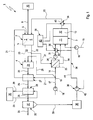
- FIG. 1 shows a highly simplified, schematics-like schematic representation of a fuel cell system.
- Corresponding Fig. 1 includes a fuel cell system 1, which may be arranged in a vehicle, at least one fuel cell 2, a reformer 3 and a residual gas burner 4.
- the fuel cell 2 serves to generate electric current from an anode gas containing hydrogen gas and a cathode gas containing oxygen gas.
- the fuel cell 2 an electrolyte 5, which separates an anode side 6 of a cathode side 7 in the fuel cell 2.
- the fuel cell 2 comprises a plurality of individual fuel cell elements which are stacked on each other, so that the fuel cell 2 is usually referred to as "STACK".
- the fuel cell 2 is preferably a high-temperature fuel cell, which may be embodied in particular as a solid-state fuel cell, preferably as an SOFC fuel cell. Alternatively, it is basically also possible to design the fuel cell 2 as a low-temperature fuel cell, in particular as a PEM fuel cell, which operates with a proton transport membrane or with a polymer electrolyte membrane.
- the fuel cell 2 has at least one electrical connection 8, to which the electrical current generated by the fuel cell 2 can be tapped off via a corresponding power line 9 and fed to a fundamentally arbitrary electrical consumer 10.
- the load 10 is, for example, an electrical vehicle electrical system of the vehicle, so that in principle all electrical consumers of the vehicle can be supplied with electrical energy with the aid of the fuel cell system 1.
- the fuel cell system 1 only for electrical supply individual special electrical load 10 of the vehicle is used, for example, when an internal combustion engine of the vehicle is turned off.
- the reformer 3 is configured to generate a hydrogen gas-containing reformate gas, namely, the anode gas, from a hydrogen-containing fuel and an oxygen-containing oxidizer.
- the oxidizer is preferably air.
- the fuel is preferably any hydrocarbon, such as diesel, gasoline, biodiesel, natural gas.
- the fuel cell system 1 uses as fuel for the reformer 3 a fuel which is already available for supplying the internal combustion engine of the vehicle in a motor vehicle equipped with the fuel cell system 1.
- the reformer 3 has on the input side an evaporation and mixture-forming section 11 and on the output side contains a reforming section 12, in which a catalytic converter 13 can be arranged.
- the reformer 3 is supplied to the input side of the oxidizer.
- the fuel is supplied to the reformer 3 on the input side.
- the Oxidator effet 14 branches off from a supply line 17, in which a conveyor 18, for example a pump or a fan, is arranged to drive the oxidizer.
- a corresponding branch point is designated 19 here.
- evaporation and mixture forming section 11 takes place evaporation of the usually liquid fuel.
- the heat required for this purpose can be generated for example by means of cold combustion or cold flame.
- a thorough mixing of the vaporized fuel with the gaseous oxidizer takes place here.
- the mixture fed to the reforming section 12 is substoichiometric, whereby partial oxidation can be realized in the catalytic converter 13 so as to generate the desired reformate or anode gas.
- the anode gas is conducted via an anode gas line 20 from the output side of the reformer 3 to an anode-side input side of the fuel cell 2.
- a cathode gas line 21 is provided which, for example, likewise branches off from the supply line 17 at the branch point 19, so that a common delivery device 18 is sufficient, the fuel cell 2 and the reformer 3 supply with oxidizer or cathode gas.
- an anode exhaust gas leaving the fuel cell 2 at the anode side 6 contains more or less hydrogen gas.
- a cathode exhaust gas leaving the fuel cell 2 on the cathode side 7 contains more or less oxygen gas.
- the anode exhaust gas is supplied to the residual gas burner 4 via an anode exhaust gas line 22.
- the cathode exhaust gas is via a cathode exhaust gas line 23 also fed to the residual gas burner 4.
- mixing of anode exhaust gas and cathode exhaust gas take place in a combustion chamber 24 of the residual gas burner.
- the residual gas burner 4 is designed such that a combustion of anode exhaust gas with cathode exhaust gas can be realized therein, with comparatively hot burner exhaust gases being produced, which are discharged from the combustion chamber 24 or from the residual gas burner 3 via a burner exhaust line 25.
- a cooling gas line 26 can be connected to the residual gas burner 4, preferably on the cathode side, via which a cooling gas, for example air, can be introduced into the combustion chamber 24.
- this cooling gas line 26 can branch off from the supply line 17, for example at the branch point 19.
- the residual gas burner 4 can - as shown here - form a separate component with respect to the fuel cell 2. In principle, however, an embodiment is conceivable in which the residual gas burner 4 is integrated on the output side into the fuel cell 2.
- At least one heat exchanger can be arranged.
- two heat exchangers are provided, namely a main heat exchanger 27 and an additional heat exchanger 28.
- the main heat exchanger 27 is on the one hand in the burner exhaust pipe 25 and on the other hand integrated into the cathode gas line 21, whereby it is possible to transfer heat from the burner exhaust gas to the cathode gas. This can improve the fuel cell process.
- the main heat exchanger can - as shown here - with respect to the residual gas burner 4 form a separate component. In principle, however, the main heat exchanger can be structurally integrated into the outlet side of the residual gas burner 4.
- the auxiliary heat exchanger 28 is integrated on the one hand in the burner exhaust gas line 25 and on the other hand in a heating line 29 and thereby enables the transfer of heat from the burner exhaust gas to a transported in the heating line 29 heat transfer medium.
- the heating line 29 is useful for supplying a heat sink 30 or a heat consumer 30 with heat.
- the heat consumer 30 may be, for example, a heater, with the help of a vehicle interior can be heated.
- the heat sink 30 may, for example, be a cooling circuit of an internal combustion engine, which is arranged in the vehicle equipped with the fuel cell system 1. On the waste heat of the burner exhaust 25 thus the internal combustion engine can be heated.
- the additional heat exchanger 28 is designed here with respect to the main heat exchanger 27 as a separate component. In principle, an embodiment is possible in which the main heat exchanger 27 and the additional heat exchanger 28 form an integral component.
- the fuel cell system 1 also has a recirculation line 31, which, for example, branches off at a branch point 32 from the anode exhaust gas line 22 and is connected on the input side to the reformer 3. About the recirculation line 31, a part of the anode exhaust gas may be returned to the input side of the reformer 3, which improves the reforming process and, in particular, increases the efficiency of the fuel cell system 1.
- a Rezirkulationskortechniktrager 33 may be integrated, which may also be integrated, for example, in the Oxidatortechnisch 14. In principle, it is also possible to also integrate the recirculation heat exchanger 33 into the cathode gas line 21.
- the recirculation heat exchanger 33 By means of the recirculation heat exchanger 33, it is possible to transfer heat from the recycled anode exhaust gas, for example, to the oxidizer.
- the cooling of the recirculated anode exhaust gas achieved in this way makes it possible, downstream of the recirculation heat transfer 33 in the recirculation line 31, to arrange a delivery device 34, for example a pump, a blower or a compressor, which can be realized relatively inexpensively owing to the reduced requirements on temperature stability.
- the fuel cell system 1 is also equipped with a water extraction device 35 and with a water supply device 36.
- the water extraction device 35 is designed so that it makes it possible to remove water from the burner exhaust gas.
- the water extraction device 35 for this purpose have a Kondensatabscheider 37, which is arranged in the burner exhaust gas line 25.
- the heat exchanger 27, 28 it is in principle possible to cool the burner exhaust gas below the dew point of water, whereby the in Burner exhaust entrained water condenses and in the downstream of the heat exchanger 27, 28 arranged condensate 37 can be eliminated from the burner exhaust gas.
- the separated, liquid water can be collected or stored, for example, in a water reservoir 38.
- a manifold 39 connects the condensate 37 with the water tank 38.
- a filter may be arranged to filter out impurities from the condensate.
- the water supply device 36 is configured such that water can be supplied to the reformer 3 and / or the fuel cell 2.
- the water supply device 36 has at least one injection nozzle 40 for this purpose.
- two such injection nozzles 40 are indicated by way of example.
- the water can be injected, in particular in liquid form, into a gas stream supplied to the reformer 3 or into a gas stream supplied to the fuel cell 2. Within this gas stream, it then expediently due to the relatively high temperatures to an evaporation of the water, so that the water is ultimately supplied to the gas reformer 3 and the fuel cell 2.
- one of these injection nozzles 40 is arranged on or in the recirculation line 31, in particular downstream of the conveyor 34.
- the water supply device 36 can supply water to the reformer 3 or water vapor on the input side.
- this injector 40 for example, also on or be arranged in the Oxidatortechnisch 14 downstream of the Rezirkulationskorübertragers 33.
- this injection nozzle 40 it is basically possible to arrange this injection nozzle 40 in or on the fuel line 15 downstream of the conveyor 16, if the reformer 3, a gaseous fuel is supplied.
- the water supply device 36 further comprises a water supply line 41, which is connected at one end to the water reservoir 38 and the other end to the injection nozzles 40 and in which a conveyor 42, e.g. a pump may be arranged to drive the water from the water reservoir 38 to the injectors 40.
- a conveyor 42 e.g. a pump
- the water supply device 36 also includes a feed control 43, which is used in particular for actuating the injection nozzles 40 and the conveyor 42 and by means of which the metering of water to the reformer 3 and to the fuel cell 2 can be controlled.
- the fuel cell system 1 operates as follows:
- soot particles that can be deposited in particular on the catalyst 13 and at the anode or on the anode side of the electrolyte 5 and thus reduce the respective active surface, which reduces the effectiveness of the fuel cell system 1 accordingly.
- a warm-up operation comparatively much water falls in the combustion exhaust gas, especially when the fuel cell 2 has not yet reached its operating temperature, so that no current can be tapped off and the anode gas generated by the reformer 3 quasi exits the fuel cell 2 unchanged.
- the burner exhaust gas is expediently cooled below the thawing temperature of the water, whereby it can be removed in a particularly simple manner via the condensate separator 37 from the water extraction device 35 from the burner exhaust gas.
- the water thus removed can be collected in the water reservoir 38.
- the feed control 43 can now supply water to the reformer 3 or the fuel cell 2 on the input side to regenerate the reformer 3 or the catalyst 13 and / or to regenerate the fuel cell 2 or the anode.
- the water is injected into the recirculation line 31, whereby it evaporates due to the comparatively hot recycled anode exhaust gas and enters the gas reformer 3 and the catalyst 13 passes.
- the water may be injected into the anode gas line 20, thereby vaporizing due to the relatively high temperature of the anode gas and gaseously enters the fuel cell 2 and there can act on the anode or the anode side of the electrolyte 5.
- the soot deposition in the reformer 3 or at the catalyst 13 and / or the soot deposition in the fuel cell 2 or at the anode or the electrolyte 5 can be removed or at least reduced by the carbon with the water at appropriate temperatures to hydrogen and carbon dioxide is implemented.
- the regeneration process of the reformer 3 and / or the fuel cell 2 may be e.g. be controlled by means of appropriate maps and / or regulated by means of a corresponding sensor.
- this regeneration is already realized during the warm-up phase of the fuel cell system 1, so that the fuel cell system 1 is ready comparatively quickly for the realization of a particularly high efficiency.
Landscapes
- Engineering & Computer Science (AREA)
- Chemical & Material Sciences (AREA)
- Life Sciences & Earth Sciences (AREA)
- Manufacturing & Machinery (AREA)
- Sustainable Development (AREA)
- Sustainable Energy (AREA)
- Chemical Kinetics & Catalysis (AREA)
- Electrochemistry (AREA)
- General Chemical & Material Sciences (AREA)
- Combustion & Propulsion (AREA)
- Fuel Cell (AREA)
- Electric Propulsion And Braking For Vehicles (AREA)
Description
Die vorliegende Erfindung betrifft ein Brennstoffzellensystem, insbesondere in einem Kraftfahrzeug, mit den Merkmalen des Oberbegriffs des Anspruchs 5. Die Erfindung betrifft außerdem ein Verfahren zum Betreiben eines Brennstoffzellensystems mit den Merkmalen des Oberbegriffs des Anspruchs 1.The present invention relates to a fuel cell system, in particular in a motor vehicle, with the features of the preamble of
Üblicherweise umfasst ein Brennstoffzellensystem zumindest eine Brennstoffzelle zum Generieren von elektrischem Strom aus einem Wasserstoffgas enthaltenden Anodengas und einem Sauerstoffgas enthaltenden Kathodengas. Das Anodengas kann dabei mit Hilfe eines Reformers bereitgestellt werden, der das Anodengas aus einem Wasserstoff enthaltenden Brennstoff, vorzugsweise ein Kohlenwasserstoff, und einem Sauerstoff enthaltenden Oxidator, zum Beispiel Luft, generiert.Usually, a fuel cell system includes at least one fuel cell for generating electric power from an anode gas containing hydrogen gas and a cathode gas containing oxygen gas. The anode gas may be provided by means of a reformer which generates the anode gas from a hydrogen-containing fuel, preferably a hydrocarbon, and an oxygen-containing oxidizer, for example air.
Im Betrieb des Reformers können sich grundsätzlich Verunreinigungen, wie zum Beispiel Rußpartikel, bilden, insbesondere während einer Warmlaufphase oder Startphase des Reformers beziehungsweise des Brennstoffzellensystems. Diese Verunreinigungen können sich einerseits an einem Elektrolyten der Brennstoffzelle und andererseits an einem Katalysator des Reformers ablagern. Diese Ablagerungen reduzieren die aktive Oberfläche des Elektrolyten beziehungsweise des Katalysators. Mit dieser Verunreinigung nimmt somit der Wirkungsgrad des Brennstoffzellensystems ab.During operation of the reformer, impurities, such as soot particles, can generally form, in particular during a warm-up phase or start-up phase of the reformer or of the fuel cell system. These impurities may be on the one hand to an electrolyte of the fuel cell and on the other hand to a catalyst of the Deposit reformer. These deposits reduce the active surface of the electrolyte or the catalyst. With this contamination thus decreases the efficiency of the fuel cell system.
Aus der
Auch aus der
Schließlich ist aus der
Die vorliegende Erfindung beschäftigt sich mit dem Problem, für ein Brennstoffzellensystem beziehungsweise für ein zugehöriges Betriebsverfahren eine verbesserte Ausführungsform anzugeben, die es insbesondere ermöglicht, die Ablagerungen in der Brennstoffzelle beziehungsweise im Reformer zu reduzieren beziehungsweise zu entfernen, wobei diese Regeneration insbesondere während des ordnungsgemäßen, normalen Betriebs des Brennstoffzellensystems durchführbar sein soll.The present invention is concerned with the problem of providing for a fuel cell system or for an associated operating method, an improved embodiment, which in particular allows the deposits in the fuel cell or in the reformer to reduce or remove, this regeneration should be feasible in particular during the proper normal operation of the fuel cell system.
Dieses Problem wird erfindungsgemäß durch die Gegenstände der unabhängigen Ansprüche gelöst. Vorteilhafte Ausführungsformen sind Gegenstand der abhängigen Ansprüche.This problem is solved according to the invention by the subject matters of the independent claims. Advantageous embodiments are the subject of the dependent claims.
Die Erfindung beruht auf dem allgemeinen Gedanken, den Reformer und/oder die Brennstoffzelle mit Hilfe von Wasser beziehungsweise Wasserdampf zu regenerieren, das auf geeignete Weise dem Reformer beziehungsweise der Brennstoffzelle eingangsseitig zugeführt wird. Das hierzu benötigte Wasser kann dabei einem Brennerabgas entnommen werden, das in einem Restgasbrenner bei der Verbrennung von Wasserstoffgas enthaltenden Anodenabgas mit Sauerstoffgas enthaltenden Kathodenabgas entsteht. Bei der Reaktion von Wasserstoff mit Sauerstoff entsteht Wasser, so dass das Brennerabgas Wasser enthält. Dieses Wasser kann nun erfindungsgemäß dem Brennerabgas entnommen werden und dem Reformer beziehungsweise der Brennstoffzelle zu deren Regeneration zugeführt werden. Mit Hilfe von Wasser beziehungsweise Wasserdampf lassen sich Rußablagerungen bei entsprechenden Temperaturen vergasen, das bedeutet, dass das Wasser mit dem Kohlenstoff reagiert und dabei Wasserstoff und Kohlendioxid bildet. Somit lassen sich gegebenenfalls anfallende Rußablagerungen in der Brennstoffzelle beziehungsweise im Reformer entfernen.The invention is based on the general idea to regenerate the reformer and / or the fuel cell with the aid of water or water vapor, which is supplied in an appropriate manner to the reformer or the fuel cell on the input side. The water required for this purpose can be taken from a burner exhaust gas, which is produced in a residual gas burner during the combustion of hydrogen gas-containing anode exhaust gas containing oxygen gas cathode exhaust gas. In the reaction of hydrogen with oxygen, water is produced so that the burner exhaust gas contains water. This water can now be removed according to the invention the burner exhaust gas and the reformer or the fuel cell are fed to their regeneration. With the help of water or steam, soot deposits can be gasified at appropriate temperatures, which means that the water reacts with the carbon and thereby forms hydrogen and carbon dioxide. Thus, any resulting soot deposits in the fuel cell or in the reformer can be removed.
Erfindungsgemäß wird dem Reformer Anodenabgas von der Brennstoffzelle rückgeführt und das Wasser wird dem der Brennstoffzelle zugeführten Anodengas und/oder dem dem Reformer rückgeführten Anodenabgas zugeführt. Da sowohl das Anodengas als auch das rückgeführte Anodenabgas vergleichsweise hohe Temperaturen besitzen, kann das zugeführte Wasser rasch verdampfen bzw. gasförmig werden.According to the invention, anode exhaust gas is returned to the reformer from the fuel cell, and the water is supplied to the anode gas supplied to the fuel cell and / or to the anode exhaust gas recycled to the reformer. Since both the anode gas and the recycled anode exhaust gas have comparatively high temperatures, the supplied water can rapidly vaporize or become gaseous.
Da das zur Regeneration benötigte Wasser innerhalb des Brennstoffzellensystems ohnehin bereitgestellt werden kann und somit eine externe Wasserversorgung entfällt, lässt sich eine derartige Regeneration vergleichsweise preiswert realisieren.Since the water required for regeneration can be provided within the fuel cell system anyway and thus eliminates an external water supply, such a regeneration can be realized relatively inexpensively.
Gemäß einer vorteilhaften Ausführungsform kann das Wasser dem Brennerabgas durch Kondensation entnommen werden. Hierzu wird das Brennerabgas unter den Taupunkt des Wassers abgekühlt. Das sich dabei bildende Kondensat kann dann vergleichsweise einfach, beispielsweise mit einem geeigneten Kondensatabscheider, aus dem Brennerabgas entnommen werden. Das flüssige Wasser lässt sich außerdem einfach sammeln, zum Beispiel in einem entsprechenden Wasserspeicher, wodurch Betriebsphasen des Brennstoffzellensystems, in denen vergleichsweise viel Wasser im Brennerabgas enthalten ist, zum Aufladen beziehungsweise Befüllen des Wasserspeichers genutzt werden können, so dass auch in Betriebsphasen, in denen vergleichsweise wenig Wasser im Brennerabgas enthalten ist, eine Regeneration des Reformers und/oder der Brennstoffzelle mit Wasser aus dem Wasserspeicher durchführbar ist.According to an advantageous embodiment, the water can be removed from the burner exhaust gas by condensation. For this purpose, the burner exhaust gas is cooled below the dew point of the water. The condensate which forms can then be removed from the burner exhaust gas comparatively easily, for example with a suitable condensate separator. The liquid water can also be easily collected, for example, in a corresponding water storage, whereby operating phases of the fuel cell system, in which comparatively much water contained in the burner exhaust gas can be used to charge or fill the water reservoir, so that even in operating phases in which comparatively contains little water in the burner exhaust gas, a regeneration of the reformer and / or the fuel cell with water from the water tank is feasible.
Des weiteren kann das flüssige Wasser besonders einfach in einen dem Reformer oder der Brennstoffzelle zugeführten Gasstrom eingedüst werden, so dass es verdampft und anschließend gasförmig in den Reformer beziehungsweise die Brennstoffzelle eintritt.Furthermore, the liquid water can be injected in a particularly simple manner into a gas stream supplied to the reformer or the fuel cell, so that it evaporates and then enters the reformer or the fuel cell in gaseous form.
Weitere wichtige Merkmale und Vorteile der Erfindung ergeben sich aus den Unteransprüchen, aus der Zeichnung und aus der zugehörigen Figurenbeschreibung anhand der Zeichnung.Other important features and advantages of the invention will become apparent from the dependent claims, from the drawing and from the associated description of the figures with reference to the drawing.
Es versteht sich, dass die vorstehend genannten und die nachstehend noch zu erläuternden Merkmale nicht nur in der jeweils angegebenen Kombination, sondern auch in anderen Kombinationen oder in Alleinstellung verwendbar sind, ohne den Rahmen der vorliegenden Erfindung zu verlassen.It is understood that the features mentioned above and those yet to be explained below can be used not only in the particular combination given, but also in other combinations or in isolation, without departing from the scope of the present invention.
Bevorzugte Ausführungsbeispiele der Erfindung sind in der Zeichnung dargestellt und werden in der nachfolgenden Beschreibung näher erläutert.Preferred embodiments of the invention are illustrated in the drawings and will be explained in more detail in the following description.
Die einzige
Entsprechend
Der Reformer 3 ist so ausgestaltet, dass er ein Wasserstoffgas enthaltendes Reformatgas, nämlich das Anodengas, aus einem Wasserstoff enthaltenden Brennstoff und einem Sauerstoff enthaltenden Oxidator generieren kann. Beim Oxidator handelt es sich vorzugsweise um Luft. Beim Brennstoff handelt es sich vorzugsweise um einen beliebigen Kohlenwasserstoff, wie zum Beispiel Diesel, Benzin, Biodiesel, Erdgas. Vorzugsweise verwendet das Brennstoffzellensystem 1 als Brennstoff für den Reformer 3 einen Kraftstoff, der in einem mit dem Brennstoffzellensystem 1 ausgestatteten Kraftfahrzeug ohnehin zur Versorgung der Brennkraftmaschine des Fahrzeugs zur Verfügung steht. Der Reformer 3 weist eingangsseitig einen Verdampfungs- und Gemischbildungsabschnitt 11 auf und enthält ausgangsseitig einen Reformatbildungsabschnitt 12, in dem ein Katalysator 13 angeordnet sein kann. Über eine Oxidatorleitung 14 wird dem Reformer 3 eingangsseitig der Oxidator zugeführt. Mit einer Brennstoffleitung 15 wird dem Reformer 3 eingangsseitig der Brennstoff zugeführt. Hierzu kann die Brennstoffleitung 15 eine Fördereinrichtung 16, insbesondere eine Pumpe, enthalten, die den Brennstoff zum Reformer 3 hin antreibt. Im vorliegenden Fall zweigt die Oxidatorleitung 14 von einer Versorgungsleitung 17 ab, in der eine Fördereinrichtung 18, zum Beispiel eine Pumpe oder ein Gebläse, angeordnet ist, um den Oxidator anzutreiben. Eine entsprechende Abzweigstelle ist hier mit 19 bezeichnet. Im Verdampfungs- und Gemischbildungsabschnitt 11 erfolgt eine Verdampfung des in der Regel flüssigen Brennstoffs. Die hierzu erforderliche Wärme kann beispielsweise mittels kalter Verbrennung beziehungsweise kalter Flamme erzeugt werden. Des weiteren erfolgt hier eine Durchmischung des verdampften Brennstoffs mit dem gasförmigen Oxidator. Das dem Reformatbildungsabschnitt 12 zugeführte Gemisch ist unterstöchiometrisch, wodurch im Katalysator 13 eine partielle Oxidation realisierbar ist, um so das gewünschte Reformat beziehungsweise Anodengas zu generieren. Das Anodengas wird über eine Anodengasleitung 20 von der Ausgangsseite des Reformers 3 an eine anodenseitige Eingangsseite der Brennstoffzelle 2 geleitet.The
Zur Versorgung der Kathodenseite 7 mit Kathodengas, bei dem es sich vorzugsweise um Luft handelt, ist eine Kathodengasleitung 21 vorgesehen, die beispielsweise ebenfalls bei der Abzweigstelle 19 von der Versorgungsleitung 17 abzweigt, so dass eine gemeinsame Fördereinrichtung 18 ausreicht, die Brennstoffzelle 2 und den Reformer 3 mit Oxidator beziehungsweise Kathodengas zu versorgen.To supply the cathode side 7 with cathode gas, which is preferably air, a
Je nach Strombedarf enthält ein Anodenabgas, das die Brennstoffzelle 2 an der Anodenseite 6 verlässt, mehr oder weniger Wasserstoffgas. Ebenso enthält ein Kathodenabgas, das die Brennstoffzelle 2 an der Kathodenseite 7 verlässt, mehr oder weniger Sauerstoffgas. Das Anodenabgas wird über eine Anodenabgasleitung 22 dem Restgasbrenner 4 zugeführt. Unabhängig davon wird das Kathodenabgas über eine Kathodenabgasleitung 23 ebenfalls dem Restgasbrenner 4 zugeführt. Vorzugsweise kommt es erst im Restgasbrenner 4 zu einer Durchmischung von Anodenabgas und Kathodenabgas in einem Brennraum 24 des Restgasbrenners. Der Restgasbrenner 4 ist so ausgestaltet, dass darin eine Verbrennung von Anodenabgas mit Kathodenabgas realisierbar ist, wobei vergleichsweise heiße Brennerabgase entstehen, die aus dem Brennraum 24 beziehungsweise vom Restgasbrenner 3 über eine Brennerabgasleitung 25 abgeführt werden. Zusätzlich kann an den Restgasbrenner 4, vorzugsweise kathodenseitig, eine Kühlgasleitung 26 angeschlossen sein, über die ein Kühlgas, zum Beispiel Luft, in den Brennraum 24 einbringbar ist. Vorzugsweise kann diese Kühlgasleitung 26 von der Versorgungsleitung 17 abzweigen, zum Beispiel bei der Abzweigstelle 19. Der Restgasbrenner 4 kann - wie hier gezeigt - bezüglich der Brennstoffzelle 2 ein separates Bauteil bilden. Grundsätzlich ist jedoch eine Ausführungsform denkbar, bei welcher der Restgasbrenner 4 ausgangsseitig in die Brennstoffzelle 2 integriert ist.Depending on the power requirement, an anode exhaust gas leaving the
In der Brennerabgasleitung 25 kann zumindest ein Wärmeübertrager angeordnet sein. Im dargestellten Ausführungsbeispiel sind zwei Wärmeübertrager vorgesehen, nämlich ein Hauptwärmeübertrager 27 und ein Zusatzwärmeübertrager 28. Der Hauptwärmeübertrager 27 ist einerseits in die Brennerabgasleitung 25 und andererseits in die Kathodengasleitung 21 eingebunden, wodurch es möglich ist, Wärme vom Brennerabgas auf das Kathodengas zu übertragen. Hierdurch lässt sich der Brennstoffzellenprozess verbessern. Der Hauptwärmeübertrager kann - wie hier gezeigt - bezüglich des Restgasbrenners 4 ein separates Bauteil bilden. Grundsätzlich kann der Hauptwärmeübertrager jedoch baulich in die Ausgangsseite des Restgasbrenners 4 integriert sein.In the burner
Der Zusatzwärmeübertrager 28 ist einerseits in die Brennerabgasleitung 25 und andererseits in eine Heizleitung 29 integriert und ermöglicht dadurch die Übertragung von Wärme aus dem Brennerabgas auf ein in der Heizleitung 29 transportiertes Wärmeübertragungsmedium. Die Heizleitung 29 dient zweckmäßig zur Versorgung einer Wärmesenke 30 oder eines Wärmeverbrauchers 30 mit Wärme. Beim Wärmeverbraucher 30 kann es sich beispielsweise um ein Heizgerät handeln, mit dessen Hilfe ein Fahrzeuginnenraum beheizt werden kann. Ebenso kann es sich bei der Wärmesenke 30 beispielsweise um einen Kühlkreis einer Brennkraftmaschine handeln, die in dem mit dem Brennstoffzellensystem 1 ausgestatteten Fahrzeug angeordnet ist. Über die Abwärme des Brennerabgases 25 kann somit die Brennkraftmaschine aufgeheizt werden. Der Zusatzwärmeübertrager 28 ist hier bezüglich des Hauptwärmeübertragers 27 als separates Bauteil ausgestaltet. Grundsätzlich ist auch eine Ausführungsform möglich, bei welcher der Hauptwärmeübertrager 27 und der Zusatzwärmeübertrager 28 ein integrales Bauteil bilden.The
Das Brennstoffzellensystem 1 weist außerdem eine Rezirkulationsleitung 31 auf, die zum Beispiel bei einer Abzweigstelle 32 von der Anodenabgasleitung 22 abzweigt und an den Reformer 3 eingangsseitig angeschlossen ist. Über die Rezirkulationsleitung 31 kann ein Teil des Anodenabgases zur Eingangsseite des Reformers 3 rückgeführt werden, was den Reformerprozess verbessert und insbesondere den Wirkungsgrad des Brennstoffzellensystems 1 erhöht. In der Rezirkulationsleitung 31 kann ein Rezirkulationswärmeübertrager 33 eingebunden sein, der außerdem zum Beispiel in die Oxidatorleitung 14 eingebunden sein kann. Grundsätzlich ist es auch möglich, den Rezirkulationswärmeübertrager 33 ebenfalls in die Kathodengasleitung 21 einzubinden. Mit Hilfe des Rezirkulationswärmeübertragers 33 ist es möglich, Wärme vom rückgeführten Anodenabgas zum Beispiel auf den Oxidator zu übertragen. Die hierdurch erzielte Kühlung des rückgeführten Anodenabgases ermöglicht es, stromab des Rezirkulationswärme-übertragers 33 in der Rezirkulationsleitung 31 eine Fördereinrichtung 34, zum Beispiel eine Pumpe, ein Gebläse oder einen Verdichter, anzuordnen, die aufgrund der reduzierten Anforderungen an die Temperaturbeständigkeit vergleichsweise preiswert realisierbar ist.The fuel cell system 1 also has a
Das erfindungsgemäße Brennstoffzellensystem 1 ist außerdem mit einer Wasserentnahmeeinrichtung 35 sowie mit einer Wasserzuführeinrichtung 36 ausgestattet. Die Wasserentnahmeeinrichtung 35 ist so ausgestaltet, dass sie es ermöglicht, dem Brennerabgas Wasser zu entnehmen. Beispielsweise kann die Wasserentnahmeeinrichtung 35 zu diesem Zweck einen Kondensatabscheider 37 aufweisen, der in der Brennerabgasleitung 25 angeordnet ist. Insbesondere mit Hilfe der Wärmeübertrager 27, 28 ist es grundsätzlich möglich, das Brennerabgas unter den Taupunkt von Wasser abzukühlen, wodurch das im Brennerabgas mitgeführte Wasser kondensiert und in dem stromab der Wärmeübertrager 27, 28 angeordneten Kondensatabscheider 37 aus dem Brennerabgas ausgeschieden werden kann. Das ausgeschiedene, flüssige Wasser kann beispielsweise in einem Wasserspeicher 38 gesammelt beziehungsweise gespeichert werden. Dabei verbindet beispielsweise eine Sammelleitung 39 den Kondensatabscheider 37 mit dem Wasserspeicher 38. In der Sammelleitung 39 kann ein Filter angeordnet sein, um Verunreinigungen aus dem Kondensat herauszufiltern.The fuel cell system 1 according to the invention is also equipped with a
Die Wasserzuführeinrichtung 36 ist so ausgestaltet, dass damit Wasser dem Reformer 3 und/oder der Brennstoffzelle 2 zuführbar ist. Beispielsweise weist die Wasserzuführeinrichtung 36 hierzu zumindest eine Einspritzdüse 40 auf. Im gezeigten Beispiel sind zwei derartige Einspritzdüsen 40 exemplarisch angedeutet. Mit Hilfe dieser Einspritzdüsen 40 kann das Wasser insbesondere in flüssiger Form in einen dem Reformer 3 zugeführten Gasstrom beziehungsweise in einen der Brennstoffzelle 2 zugeführten Gasstrom eingedüst werden. Innerhalb dieses Gasstroms kommt es dann zweckmäßig aufgrund der relativ hohen Temperaturen zu einer Verdampfung des Wassers, so dass das Wasser letztlich gasförmig dem Reformer 3 beziehungsweise der Brennstoffzelle 2 zugeführt wird. Beispielsweise ist eine dieser Einspritzdüsen 40 an oder in der Rezirkulationsleitung 31, insbesondere stromab der Fördereinrichtung 34, angeordnet. Mit dieser Einspritzdüse 40 kann die Wasserzuführeinrichtung 36 dem Reformer 3 Wasser beziehungsweise Wasserdampf eingangsseitig zuführen. Alternativ kann diese Einspritzdüse 40 beispielsweise auch an oder in der Oxidatorleitung 14 stromab des Rezirkulationswärmeübertragers 33 angeordnet sein. Ebenso ist es grundsätzlich möglich, diese Einspritzdüse 40 in oder an der Brennstoffleitung 15 stromab der Fördereinrichtung 16 anzuordnen, sofern dem Reformer 3 ein gasförmiger Brennstoff zugeführt wird.The
Für die Versorgung der Brennstoffzelle 2 mit Wasser beziehungsweise Wasserdampf kann eine solche Einspritzdüse 40 an oder in der Anodengasleitung 20 angeordnet sein. Auf diese Weise gelangt das Wasser beziehungsweise der Wasserdampf auf die Anodenseite 6 der Brennstoffzelle 2. Die Wasserzuführeinrichtung 36 umfasst ferner eine Wasserzuführleitung 41, die einenends zum Beispiel an den Wasserspeicher 38 und anderenends an die Einspritzdüsen 40 angeschlossen ist und in der eine Fördereinrichtung 42, z.B. eine Pumpe, angeordnet sein kann, um das Wasser vom Wasserspeicher 38 zu den Einspritzdüsen 40 anzutreiben.For supplying the
Die Wasserzuführeinrichtung 36 umfasst außerdem eine Zuführsteuerung 43, die insbesondere zur Betätigung der Einspritzdüsen 40 sowie der Fördereinrichtung 42 dient und mit deren Hilfe die Zumessung von Wasser zum Reformer 3 sowie zur Brennstoffzelle 2 steuerbar ist.The
Im Betrieb des Brennstoffzellensystems 1, insbesondere beim Hochfahren oder Warmlaufen des Brennstoffzellensystems 1 können sich Rußpartikel bilden, die sich insbesondere am Katalysator 13 sowie an der Anode beziehungsweise an der Anodenseite des Elektrolyten 5 ablagern können und so die jeweilige aktive Oberfläche reduzieren, was die Effektivität des Brennstoffzellensystems 1 entsprechend senkt. Insbesondere bei einem derartigen Warmlaufbetrieb fällt im Brennabgas vergleichsweise viel Wasser an, insbesondere dann, wenn die Brennstoffzelle 2 ihre Betriebstemperatur noch nicht erreicht hat, so dass daran kein Strom abgreifbar ist und das vom Reformer 3 generierte Anodengas quasi unverändert aus der Brennstoffzelle 2 austritt. Über die Wärmeübertrager 27 und 28 erfolgt eine Abkühlung des Brennerabgases zweckmäßig unter die Tautemperatur des Wassers, wodurch dieses besonders einfach über den Kondensatabscheider 37 von der Wasserentnahmeeinrichtung 35 aus den Brennerabgas entnehmbar ist. Das so entnommene Wasser kann im Wasserspeicher 38 gesammelt werden.During operation of the fuel cell system 1, in particular during startup or warm-up of the fuel cell system 1 can form soot particles that can be deposited in particular on the
Die Zuführsteuerung 43 kann nun zum Regenerieren des Reformers 3 beziehungsweise des Katalysators 13 und/oder zum Regenerieren der Brennstoffzelle 2 beziehungsweise der Anode Wasser dem Reformer 3 beziehungsweise der Brennstoffzelle 2 eingangsseitig zuführen. Vorzugsweise wird das Wasser in die Rezirkulationsleitung 31 eingedüst, wodurch es aufgrund des vergleichsweise heißen rückgeführten Anodenabgases verdampft und gasförmig in den Reformer 3 eintritt und zum Katalysator 13 gelangt. Zusätzlich oder alternativ kann das Wasser in die Anodengasleitung 20 eingedüst werden, wodurch es aufgrund der relativ hohen Temperatur des Anodengases verdampft und gasförmig in die Brennstoffzelle 2 eintritt und dort die Anode beziehungsweise die Anodenseite des Elektrolyten 5 beaufschlagen kann. Durch die Regeneration kann die Rußablagerung im Reformer 3 beziehungsweise an dessen Katalysator 13 und/oder die Rußablagerung in der Brennstoffzelle 2 beziehungsweise an der Anode beziehungsweise am Elektrolyten 5 entfernt oder zumindest reduziert werden, indem der Kohlenstoff mit dem Wasser bei entsprechenden Temperaturen zu Wasserstoff und Kohlendioxyd umgesetzt wird.The
Der Regenerationsprozess des Reformers 3 und/oder der Brennstoffzelle 2 kann z.B. mittels entsprechender Kennfelder gesteuert werden und/oder mittels einer entsprechenden Sensorik geregelt werden. Vorzugsweise wird diese Regeneration bereits während der Warmlaufphase des Brennstoffzellensystems 1 realisiert, damit das Brennstoffzellensystem 1 vergleichsweise rasch zur Realisierung eines besonders hohen Wirkungsgrads bereitsteht.The regeneration process of the
Claims (9)
- A method for operating a fuel cell system (1), in particular in a motor vehicle, comprising- at least one fuel cell (2) for generating electric current from a hydrogen gas-containing anode gas and an oxygen gas-containing cathode gas,- a reformer (3) for generating the anode gas from a hydrogen-containing fuel and an oxygen-containing oxidant,- a residual gas burner (4) for burning anode waste gas of the fuel cell (2) containing hydrogen gas with cathode waste gas of the fuel cell (2) containing oxygen gas,- in which water is removed from a burner waste gas of the residual gas burner (4) and fed to the fuel cell (2) and/or the reformer (3),characterized in that anode waste gas from the fuel cell (2) is returned to the reformer (3) and the removed water is fed to the anode gas fed to the fuel cell (2) and/or fed to the anode waste gas returned to the reformer (3).
- The method according to Claim 1, characterized in that the water is condensated out of the burner waste gas.
- The method according to Claim 1 or 2, characterized in that the water is collected in a water storage unit (38).
- The method according to any one of the Claims 1 to 3, characterized in that the water is fed to the fuel cell (2) and/or to the reformer (3) in a gaseous manner or injected in liquid manner.
- A fuel cell system, in particular in a motor vehicle,- with at least one fuel cell (2) for generating electric current from a hydrogen gas-containing anode gas and an oxygen gas-containing cathode gas,- with a reformer (3) for generating the anode gas from a hydrogen-containing fuel and an oxygen-containing oxidant,- with a residual gas burner (4) for burning anode waste gas of the fuel cell (2) containing hydrogen gas with cathode waste gas of the fuel cell (2) containing oxygen gas,- with a water removing device (35) for removing water from a burner waste gas of the residual gas burner (4),- with a water feeding device (6) for feeding water to the fuel cell (2) and/or to the reformer (3),
characterized- in that the water feeding device (36) comprises at least one injection nozzle (40), with which the water can be injected in the liquid form into a gas flow fed to the reformer (3) and/or into a gas flow fed to the fuel cell (2),- in that the water feeding device (36) is connected to an anode gas line (20) feeding the anode gas to the fuel cell (2) and/or to a recirculation line (31) returning anode waste gas from the fuel cell (2) to the reformer (3). - The fuel cell system according to Claim 5, characterized in that the water removing device (35) comprises a condensate separator (37), which is arranged in a burner waste gas line (25) discharging the burner waste gas from the residual gas burner (4).
- The fuel cell system according to Claim 5 or 6, characterized in that at least one heat transfer device (27, 28) is arranged in a burner waste gas line (25) discharging the burner waste gas from the residual gas burner (4), with which the burner waste gas can be cooled to below the dew point of the water.
- The fuel cell system according to Claim 7, characterized- in that a main heat transfer device (27) is provided, which on the one hand is incorporated in the burner waste gas line (25) and on the other hand in a cathode gas line (21) supplying the fuel cell (2) with cathode gas, and/or- in that at least one additional heat transfer device (28) is provided, which on the one hand is incorporated in the burner waste gas line (25), in particular downstream of the main heat transfer device (27) and on the other hand in a heating line (29) for supplying a heat sink (30) or a heat consumer (30) with heat, and/or- in that the condensate separator (37) is arranged in the burner waste gas line (25) downstream of the respective heat transfer device (27).
- The fuel cell system according to any one of the Claims 5 to 8, characterized in that a water storage unit (38) for collecting of in particular liquid water removed from the burner waste gas is provided, which on the one hand is connected to the water removing device (35) and on the other hand to the water feeding device (36).
Priority Applications (1)
| Application Number | Priority Date | Filing Date | Title |
|---|---|---|---|
| PL07124113T PL1944823T3 (en) | 2007-01-12 | 2007-12-28 | Fuel cell system and method of operation |
Applications Claiming Priority (1)
| Application Number | Priority Date | Filing Date | Title |
|---|---|---|---|
| DE102007002653A DE102007002653A1 (en) | 2007-01-12 | 2007-01-12 | Fuel cell system and associated operating method |
Publications (3)
| Publication Number | Publication Date |
|---|---|
| EP1944823A2 EP1944823A2 (en) | 2008-07-16 |
| EP1944823A3 EP1944823A3 (en) | 2009-10-07 |
| EP1944823B1 true EP1944823B1 (en) | 2014-03-19 |
Family
ID=39284069
Family Applications (1)
| Application Number | Title | Priority Date | Filing Date |
|---|---|---|---|
| EP07124113.7A Active EP1944823B1 (en) | 2007-01-12 | 2007-12-28 | Fuel cell system and method of operation |
Country Status (3)
| Country | Link |
|---|---|
| EP (1) | EP1944823B1 (en) |
| DE (1) | DE102007002653A1 (en) |
| PL (1) | PL1944823T3 (en) |
Families Citing this family (2)
| Publication number | Priority date | Publication date | Assignee | Title |
|---|---|---|---|---|
| DE102011087971B4 (en) * | 2011-12-08 | 2021-03-04 | Eberspächer Climate Control Systems GmbH | Method for operating a heater that can be operated with hydrocarbon fuel |
| AT521901B1 (en) * | 2018-11-19 | 2020-10-15 | Avl List Gmbh | Method for heating a fuel cell system and fuel cell system |
Family Cites Families (4)
| Publication number | Priority date | Publication date | Assignee | Title |
|---|---|---|---|---|
| US4650727A (en) * | 1986-01-28 | 1987-03-17 | The United States Of America As Represented By The United States Department Of Energy | Fuel processor for fuel cell power system |
| DE4446841A1 (en) * | 1994-12-27 | 1996-07-04 | Mtu Friedrichshafen Gmbh | Fuel cell module |
| DE19822691A1 (en) * | 1998-05-20 | 1999-11-25 | Volkswagen Ag | Fuel cell system for a vehicle |
| JP2000182647A (en) * | 1998-12-18 | 2000-06-30 | Aisin Seiki Co Ltd | Fuel cell system |
-
2007
- 2007-01-12 DE DE102007002653A patent/DE102007002653A1/en not_active Ceased
- 2007-12-28 EP EP07124113.7A patent/EP1944823B1/en active Active
- 2007-12-28 PL PL07124113T patent/PL1944823T3/en unknown
Also Published As
| Publication number | Publication date |
|---|---|
| EP1944823A3 (en) | 2009-10-07 |
| DE102007002653A1 (en) | 2008-07-17 |
| EP1944823A2 (en) | 2008-07-16 |
| PL1944823T3 (en) | 2014-11-28 |
Similar Documents
| Publication | Publication Date | Title |
|---|---|---|
| EP1060942B1 (en) | Vehicle having an internal combustion drive engine and comprising a fuel cell arrangement for the supply of current meeting the electrical requirements of the vehicle and method for operating such a vehicle | |
| EP1679757B1 (en) | Fuel cell system | |
| DE102008018152B4 (en) | Fuel cell system and associated operating method | |
| DE102011088563B4 (en) | Arrangement with fuel cell system | |
| DE102016203792A1 (en) | fuel cell module | |
| EP1947723B1 (en) | System for providing energy | |
| DE102017001564A1 (en) | Method for starting a fuel cell assembly and fuel cell assembly | |
| EP1986263B1 (en) | Fuel cell system and appropriate starting method | |
| DE10157737A1 (en) | fuel cell plant | |
| EP1944823B1 (en) | Fuel cell system and method of operation | |
| EP1739777B1 (en) | Fuel cell system for vehicles | |
| EP1985346B1 (en) | Vaporiser device | |
| WO2004079846A2 (en) | Fuel cell system comprising at least one fuel cell and one gas generating system | |
| WO2004007356A2 (en) | Method for starting a gas generating system | |
| EP1228999A2 (en) | Gas generating system for a fuel cell system and process for operation of a gas generating system | |
| EP1942537B1 (en) | Fuel cell system including a regeneration arrangement for a reformer and method thereof | |
| DE102007033150B4 (en) | Operating method for a fuel cell system | |
| DE102005030474A1 (en) | Fuel cell system for vehicles has reformate burner arrangement that sends incineration gases to fuel cell before and after anti-condensation temperature is reached by remaining hydrocarbons and water vapor in reformer | |
| EP1845577B1 (en) | Fuel cell system | |
| DE102008008907A1 (en) | Fuel cell system for use in motor vehicle, has fuel cell and gas burner, which are connected such that anode exhaust gas is supplied from anode side of cell to burner and burner exhaust gas of burner is supplied to cathode side of cell | |
| DE102009053839A1 (en) | Fuel cell system and method for operating a fuel cell system | |
| DE102007033151B4 (en) | Operating method for a fuel cell system | |
| AT524859B1 (en) | Internal combustion system with an internal combustion engine | |
| DE102007054768A1 (en) | Reformer, fuel cell and related operating procedures | |
| WO2001091217A1 (en) | Fuel cell installation with a reformer |
Legal Events
| Date | Code | Title | Description |
|---|---|---|---|
| PUAI | Public reference made under article 153(3) epc to a published international application that has entered the european phase |
Free format text: ORIGINAL CODE: 0009012 |
|
| AK | Designated contracting states |
Kind code of ref document: A2 Designated state(s): AT BE BG CH CY CZ DE DK EE ES FI FR GB GR HU IE IS IT LI LT LU LV MC MT NL PL PT RO SE SI SK TR |
|
| AX | Request for extension of the european patent |
Extension state: AL BA HR MK RS |
|
| PUAL | Search report despatched |
Free format text: ORIGINAL CODE: 0009013 |
|
| AK | Designated contracting states |
Kind code of ref document: A3 Designated state(s): AT BE BG CH CY CZ DE DK EE ES FI FR GB GR HU IE IS IT LI LT LU LV MC MT NL PL PT RO SE SI SK TR |
|
| AX | Request for extension of the european patent |
Extension state: AL BA HR MK RS |
|
| 17P | Request for examination filed |
Effective date: 20100407 |
|
| 17Q | First examination report despatched |
Effective date: 20100512 |
|
| AKX | Designation fees paid |
Designated state(s): AT BE BG CH CY CZ DE DK EE ES FI FR GB GR HU IE IS IT LI LT LU LV MC MT NL PL PT RO SE SI SK TR |
|
| RAP1 | Party data changed (applicant data changed or rights of an application transferred) |
Owner name: EBERSPAECHER CLIMATE CONTROL SYSTEMS GMBH & CO. KG |
|
| GRAP | Despatch of communication of intention to grant a patent |
Free format text: ORIGINAL CODE: EPIDOSNIGR1 |
|
| INTG | Intention to grant announced |
Effective date: 20140102 |
|
| GRAS | Grant fee paid |
Free format text: ORIGINAL CODE: EPIDOSNIGR3 |
|
| GRAA | (expected) grant |
Free format text: ORIGINAL CODE: 0009210 |
|
| AK | Designated contracting states |
Kind code of ref document: B1 Designated state(s): AT BE BG CH CY CZ DE DK EE ES FI FR GB GR HU IE IS IT LI LT LU LV MC MT NL PL PT RO SE SI SK TR |
|
| REG | Reference to a national code |
Ref country code: GB Ref legal event code: FG4D Free format text: NOT ENGLISH |
|
| REG | Reference to a national code |
Ref country code: CH Ref legal event code: EP |
|
| REG | Reference to a national code |
Ref country code: IE Ref legal event code: FG4D Free format text: LANGUAGE OF EP DOCUMENT: GERMAN |
|
| REG | Reference to a national code |
Ref country code: AT Ref legal event code: REF Ref document number: 658185 Country of ref document: AT Kind code of ref document: T Effective date: 20140415 |
|
| REG | Reference to a national code |
Ref country code: DE Ref legal event code: R096 Ref document number: 502007012876 Country of ref document: DE Effective date: 20140430 |
|
| REG | Reference to a national code |
Ref country code: NL Ref legal event code: T3 |
|
| REG | Reference to a national code |
Ref country code: SE Ref legal event code: TRGR |
|
| PG25 | Lapsed in a contracting state [announced via postgrant information from national office to epo] |
Ref country code: LT Free format text: LAPSE BECAUSE OF FAILURE TO SUBMIT A TRANSLATION OF THE DESCRIPTION OR TO PAY THE FEE WITHIN THE PRESCRIBED TIME-LIMIT Effective date: 20140319 |
|
| REG | Reference to a national code |
Ref country code: LT Ref legal event code: MG4D |
|
| PG25 | Lapsed in a contracting state [announced via postgrant information from national office to epo] |
Ref country code: CY Free format text: LAPSE BECAUSE OF FAILURE TO SUBMIT A TRANSLATION OF THE DESCRIPTION OR TO PAY THE FEE WITHIN THE PRESCRIBED TIME-LIMIT Effective date: 20140319 Ref country code: FI Free format text: LAPSE BECAUSE OF FAILURE TO SUBMIT A TRANSLATION OF THE DESCRIPTION OR TO PAY THE FEE WITHIN THE PRESCRIBED TIME-LIMIT Effective date: 20140319 |
|
| PG25 | Lapsed in a contracting state [announced via postgrant information from national office to epo] |
Ref country code: LV Free format text: LAPSE BECAUSE OF FAILURE TO SUBMIT A TRANSLATION OF THE DESCRIPTION OR TO PAY THE FEE WITHIN THE PRESCRIBED TIME-LIMIT Effective date: 20140319 |
|
| PG25 | Lapsed in a contracting state [announced via postgrant information from national office to epo] |
Ref country code: BG Free format text: LAPSE BECAUSE OF FAILURE TO SUBMIT A TRANSLATION OF THE DESCRIPTION OR TO PAY THE FEE WITHIN THE PRESCRIBED TIME-LIMIT Effective date: 20140619 Ref country code: IS Free format text: LAPSE BECAUSE OF FAILURE TO SUBMIT A TRANSLATION OF THE DESCRIPTION OR TO PAY THE FEE WITHIN THE PRESCRIBED TIME-LIMIT Effective date: 20140719 Ref country code: RO Free format text: LAPSE BECAUSE OF FAILURE TO SUBMIT A TRANSLATION OF THE DESCRIPTION OR TO PAY THE FEE WITHIN THE PRESCRIBED TIME-LIMIT Effective date: 20140319 Ref country code: EE Free format text: LAPSE BECAUSE OF FAILURE TO SUBMIT A TRANSLATION OF THE DESCRIPTION OR TO PAY THE FEE WITHIN THE PRESCRIBED TIME-LIMIT Effective date: 20140319 |
|
| PG25 | Lapsed in a contracting state [announced via postgrant information from national office to epo] |
Ref country code: SK Free format text: LAPSE BECAUSE OF FAILURE TO SUBMIT A TRANSLATION OF THE DESCRIPTION OR TO PAY THE FEE WITHIN THE PRESCRIBED TIME-LIMIT Effective date: 20140319 Ref country code: ES Free format text: LAPSE BECAUSE OF FAILURE TO SUBMIT A TRANSLATION OF THE DESCRIPTION OR TO PAY THE FEE WITHIN THE PRESCRIBED TIME-LIMIT Effective date: 20140319 |
|
| REG | Reference to a national code |
Ref country code: PL Ref legal event code: T3 |
|
| REG | Reference to a national code |
Ref country code: DE Ref legal event code: R097 Ref document number: 502007012876 Country of ref document: DE |
|
| PG25 | Lapsed in a contracting state [announced via postgrant information from national office to epo] |
Ref country code: PT Free format text: LAPSE BECAUSE OF FAILURE TO SUBMIT A TRANSLATION OF THE DESCRIPTION OR TO PAY THE FEE WITHIN THE PRESCRIBED TIME-LIMIT Effective date: 20140721 |
|
| PLBE | No opposition filed within time limit |
Free format text: ORIGINAL CODE: 0009261 |
|
| STAA | Information on the status of an ep patent application or granted ep patent |
Free format text: STATUS: NO OPPOSITION FILED WITHIN TIME LIMIT |
|
| PG25 | Lapsed in a contracting state [announced via postgrant information from national office to epo] |
Ref country code: DK Free format text: LAPSE BECAUSE OF FAILURE TO SUBMIT A TRANSLATION OF THE DESCRIPTION OR TO PAY THE FEE WITHIN THE PRESCRIBED TIME-LIMIT Effective date: 20140319 |
|
| PGFP | Annual fee paid to national office [announced via postgrant information from national office to epo] |
Ref country code: CZ Payment date: 20141219 Year of fee payment: 8 Ref country code: GB Payment date: 20141216 Year of fee payment: 8 |
|
| 26N | No opposition filed |
Effective date: 20141222 |
|
| PGFP | Annual fee paid to national office [announced via postgrant information from national office to epo] |
Ref country code: PL Payment date: 20141218 Year of fee payment: 8 Ref country code: FR Payment date: 20141212 Year of fee payment: 8 Ref country code: NL Payment date: 20141215 Year of fee payment: 8 |
|
| PG25 | Lapsed in a contracting state [announced via postgrant information from national office to epo] |
Ref country code: IT Free format text: LAPSE BECAUSE OF FAILURE TO SUBMIT A TRANSLATION OF THE DESCRIPTION OR TO PAY THE FEE WITHIN THE PRESCRIBED TIME-LIMIT Effective date: 20140319 |
|
| REG | Reference to a national code |
Ref country code: DE Ref legal event code: R097 Ref document number: 502007012876 Country of ref document: DE Effective date: 20141222 |
|
| PG25 | Lapsed in a contracting state [announced via postgrant information from national office to epo] |
Ref country code: BE Free format text: LAPSE BECAUSE OF NON-PAYMENT OF DUE FEES Effective date: 20141231 |
|
| PG25 | Lapsed in a contracting state [announced via postgrant information from national office to epo] |
Ref country code: SI Free format text: LAPSE BECAUSE OF FAILURE TO SUBMIT A TRANSLATION OF THE DESCRIPTION OR TO PAY THE FEE WITHIN THE PRESCRIBED TIME-LIMIT Effective date: 20140319 Ref country code: LU Free format text: LAPSE BECAUSE OF FAILURE TO SUBMIT A TRANSLATION OF THE DESCRIPTION OR TO PAY THE FEE WITHIN THE PRESCRIBED TIME-LIMIT Effective date: 20141228 |
|
| REG | Reference to a national code |
Ref country code: CH Ref legal event code: PL |
|
| REG | Reference to a national code |
Ref country code: IE Ref legal event code: MM4A |
|
| PG25 | Lapsed in a contracting state [announced via postgrant information from national office to epo] |
Ref country code: IE Free format text: LAPSE BECAUSE OF NON-PAYMENT OF DUE FEES Effective date: 20141228 Ref country code: CH Free format text: LAPSE BECAUSE OF NON-PAYMENT OF DUE FEES Effective date: 20141231 Ref country code: LI Free format text: LAPSE BECAUSE OF NON-PAYMENT OF DUE FEES Effective date: 20141231 |
|
| REG | Reference to a national code |
Ref country code: AT Ref legal event code: MM01 Ref document number: 658185 Country of ref document: AT Kind code of ref document: T Effective date: 20141228 |
|
| PG25 | Lapsed in a contracting state [announced via postgrant information from national office to epo] |
Ref country code: MC Free format text: LAPSE BECAUSE OF FAILURE TO SUBMIT A TRANSLATION OF THE DESCRIPTION OR TO PAY THE FEE WITHIN THE PRESCRIBED TIME-LIMIT Effective date: 20140319 Ref country code: AT Free format text: LAPSE BECAUSE OF NON-PAYMENT OF DUE FEES Effective date: 20141228 |
|
| PG25 | Lapsed in a contracting state [announced via postgrant information from national office to epo] |
Ref country code: GR Free format text: LAPSE BECAUSE OF FAILURE TO SUBMIT A TRANSLATION OF THE DESCRIPTION OR TO PAY THE FEE WITHIN THE PRESCRIBED TIME-LIMIT Effective date: 20140620 |
|
| PG25 | Lapsed in a contracting state [announced via postgrant information from national office to epo] |
Ref country code: TR Free format text: LAPSE BECAUSE OF FAILURE TO SUBMIT A TRANSLATION OF THE DESCRIPTION OR TO PAY THE FEE WITHIN THE PRESCRIBED TIME-LIMIT Effective date: 20140319 Ref country code: MT Free format text: LAPSE BECAUSE OF FAILURE TO SUBMIT A TRANSLATION OF THE DESCRIPTION OR TO PAY THE FEE WITHIN THE PRESCRIBED TIME-LIMIT Effective date: 20140319 Ref country code: HU Free format text: LAPSE BECAUSE OF FAILURE TO SUBMIT A TRANSLATION OF THE DESCRIPTION OR TO PAY THE FEE WITHIN THE PRESCRIBED TIME-LIMIT; INVALID AB INITIO Effective date: 20071228 Ref country code: CZ Free format text: LAPSE BECAUSE OF NON-PAYMENT OF DUE FEES Effective date: 20151228 |
|
| GBPC | Gb: european patent ceased through non-payment of renewal fee |
Effective date: 20151228 |
|
| REG | Reference to a national code |
Ref country code: NL Ref legal event code: MM Effective date: 20160101 |
|
| REG | Reference to a national code |
Ref country code: FR Ref legal event code: ST Effective date: 20160831 |
|
| PG25 | Lapsed in a contracting state [announced via postgrant information from national office to epo] |
Ref country code: GB Free format text: LAPSE BECAUSE OF NON-PAYMENT OF DUE FEES Effective date: 20151228 Ref country code: NL Free format text: LAPSE BECAUSE OF NON-PAYMENT OF DUE FEES Effective date: 20160101 |
|
| PG25 | Lapsed in a contracting state [announced via postgrant information from national office to epo] |
Ref country code: FR Free format text: LAPSE BECAUSE OF NON-PAYMENT OF DUE FEES Effective date: 20151231 |
|
| PG25 | Lapsed in a contracting state [announced via postgrant information from national office to epo] |
Ref country code: PL Free format text: LAPSE BECAUSE OF NON-PAYMENT OF DUE FEES Effective date: 20151228 |
|
| PGFP | Annual fee paid to national office [announced via postgrant information from national office to epo] |
Ref country code: SE Payment date: 20231219 Year of fee payment: 17 Ref country code: DE Payment date: 20231231 Year of fee payment: 17 |