EP1944732A2 - Vorrichtung und Verfahren zur Erkennung von Unschärfe, sowie Vorrichtung und Verfahren zur Unschärfenkorrektur - Google Patents
Vorrichtung und Verfahren zur Erkennung von Unschärfe, sowie Vorrichtung und Verfahren zur Unschärfenkorrektur Download PDFInfo
- Publication number
- EP1944732A2 EP1944732A2 EP08000410A EP08000410A EP1944732A2 EP 1944732 A2 EP1944732 A2 EP 1944732A2 EP 08000410 A EP08000410 A EP 08000410A EP 08000410 A EP08000410 A EP 08000410A EP 1944732 A2 EP1944732 A2 EP 1944732A2
- Authority
- EP
- European Patent Office
- Prior art keywords
- image
- blur
- images
- exposure
- short
- Prior art date
- Legal status (The legal status is an assumption and is not a legal conclusion. Google has not performed a legal analysis and makes no representation as to the accuracy of the status listed.)
- Withdrawn
Links
Images













Classifications
-
- G—PHYSICS
- G06—COMPUTING OR CALCULATING; COUNTING
- G06T—IMAGE DATA PROCESSING OR GENERATION, IN GENERAL
- G06T5/00—Image enhancement or restoration
- G06T5/73—Deblurring; Sharpening
- G06T5/75—Unsharp masking
-
- G—PHYSICS
- G06—COMPUTING OR CALCULATING; COUNTING
- G06T—IMAGE DATA PROCESSING OR GENERATION, IN GENERAL
- G06T5/00—Image enhancement or restoration
- G06T5/50—Image enhancement or restoration using two or more images, e.g. averaging or subtraction
-
- H—ELECTRICITY
- H04—ELECTRIC COMMUNICATION TECHNIQUE
- H04N—PICTORIAL COMMUNICATION, e.g. TELEVISION
- H04N23/00—Cameras or camera modules comprising electronic image sensors; Control thereof
- H04N23/60—Control of cameras or camera modules
- H04N23/68—Control of cameras or camera modules for stable pick-up of the scene, e.g. compensating for camera body vibrations
- H04N23/682—Vibration or motion blur correction
- H04N23/684—Vibration or motion blur correction performed by controlling the image sensor readout, e.g. by controlling the integration time
- H04N23/6845—Vibration or motion blur correction performed by controlling the image sensor readout, e.g. by controlling the integration time by combination of a plurality of images sequentially taken
-
- G—PHYSICS
- G06—COMPUTING OR CALCULATING; COUNTING
- G06T—IMAGE DATA PROCESSING OR GENERATION, IN GENERAL
- G06T2207/00—Indexing scheme for image analysis or image enhancement
- G06T2207/10—Image acquisition modality
- G06T2207/10141—Special mode during image acquisition
- G06T2207/10144—Varying exposure
Definitions
- the present invention relates to an apparatus and a method for detecting blur contained in an image obtained by shooting.
- the invention also relates to an apparatus and a method for correcting such blur.
- the invention relates to an image-sensing apparatus employing any of such apparatuses and methods as well.
- a motion blur correction technology is for reducing motion blur (blur in an image induced by motion of an image-shooting apparatus) occurring during shooting, and is highly valued in differentiating image-sensing apparatuses such as digital cameras. Regardless of whether the target of correction is a still image or a moving image, a motion blur correction technology can be thought of as comprising a subtechnology for detecting motion (such as camera shake) and another for correcting an image based on the detection result.
- Motion can be detected by use of a motion detection sensor such as an angular velocity sensor or an acceleration sensor, or electronically through analysis of an image.
- Motion blur can be corrected optically by driving an optical system, or electronically through image processing.
- One method to correct motion blur in a still image is to detect motion with a motion detection sensor and then correct the motion itself optically based on the detection result. Another method is to detect motion with a motion detection sensor and then correct the resulting motion blur electronically based on the detection result. Yet another method is to detect motion blur through analysis of an image and then correct it electronically based on the detection result.
- additive motion blur correction works as follows.
- an ordinary-exposure period t1 is divided such that a plurality of divided-exposure images (short-exposure images) DP1 to DP4 are shot consecutively, each with an exposure period t2.
- P NUM the number of divided-exposure images so shot
- the divided-exposure images DP1 to DP4 are then so laid on one another as to cancel the displacements among them, and are additively merged. In this way, one still image is generated that has reduced motion blur combined with the desired brightness.
- Fig. 16 is a block diagram of a configuration for executing Fourier iteration.
- Fourier iteration through iterative execution of Fourier and inverse Fourier transforms by way of modification of a deconvolved image and a point spread function (PSF), the definitive deconvolved image is estimated from a convolved (degraded) image.
- PSF point spread function
- an initial deconvolved image (the initial value of a deconvolved image) needs to be given.
- the initial deconvolved image is a random image, or a convolved image as a motion blur image.
- Fourier iteration makes it possible to generate an image less affected by motion without the need for a motion detection sensor.
- Fourier iteration is a non-linear optimization method, and it takes a large number of iteration steps to obtain an appropriate deconvolved image; that is, it takes an extremely long time to detect and correct motion blur. This makes the method difficult to put into practical use in digital still cameras and the like. A shorter processing time is a key issue to be addressed for putting it into practical use.
- motion blur is detected from an image obtained by converting a motion blur image into a two-dimensional frequency domain (see, for example, JP-A-H11-027574 ). Specifically, the image obtained by the conversion is projected onto a circle about the origin of frequency coordinates and, from the resulting projected data, the magnitude and direction of blur are found.
- this method can only estimate linear, constant-velocity blur; moreover, when the shooting subject (hereinafter also simply "subject") has a small frequency component in a particular direction, the method may fail to detect the direction of blur and thus fail to correct it appropriately. Needless to say, high accuracy in blur correction also is a key issue to be addressed.
- an object of the present invention to provide an apparatus and a method for blur detection that contribute to reduced cost and shorter processing times. It is also an object of the invention to provide an apparatus and a method for blur correction that contribute to reduced cost and higher blur correction accuracy. It is also an object of the invention to provide an image-sensing apparatus that employs any of such apparatuses and methods.
- a blur detection apparatus that detects blur contained in a first image acquired by shooting by an image sensor based on the output of the image sensor is provided with: a blur information creator adapted to create blur information reflecting the blur based on the first image and a second image shot with an exposure time shorter than the exposure time of the first image.
- the blur contained in the second image is usually smaller than that contained in the first image. Detecting the blur in the first image by referring to the second image, containing less blur, is expected to reduce the processing time for creating blur information. Moreover, there is no need to shoot a large number of images as in the conventional additive blur correction, requiring a minimum increase in load during shooting. Needless to say, there is no need to provide a sensor dedicated to the creation of blur information, and this contributes to cost reduction.
- the blur information is an image convolution function that represents the blur in the entire first image.
- the blur information creator is provided with an extractor adapted to extract partial images at least one from each of the first and second images, and creates the blur information based on the partial images.
- the blur information creator eventually finds the image convolution function through, first, provisionally finding, from a first function obtained by converting an image based on the first image into a frequency domain and a second function obtained by converting an image based on the second image into the frequency domain, an image convolution function in the frequency domain and, then, correcting, by using a predetermined restricting condition, a function obtained by converting the image convolution function thus found in the frequency domain into a space domain.
- the blur information creator calculates the blur information by Fourier iteration in which an image based on the first image and an image based on the second image are taken as a convolved image and an initial deconvolved image respectively.
- the blur information creator is provided with an extractor adapted to extract partial images at least one from each of the first and second images, and, by generating the convolved image and the initial deconvolved image from the partial images, makes the convolved image and the initial deconvolved image smaller in size than the first image.
- the blur detection apparatus is further provided with a holder adapted to hold a display image based on the output of the image sensor immediately before or after the shooting of the first image, and the blur information creator uses the display image as the second image.
- the blur information creator in the process of generating the convolved image and the initial deconvolved image from the first and second images, performs, on at least one of the image based on the first image and the image based on the second image, one or more of the following types of processing: noise elimination; brightness normalization according to the brightness level ratio between the first and second images; edge extraction; and image size normalization according to the image size ratio between the first and second images.
- the blur detection apparatus is further provided with a holder adapted to hold, as a third image, a display image based on the output of the image sensor immediately before or after the shooting of the first image, and the blur information creator creates the blur information based on the first, second, and third images.
- the blur information creator generates a fourth image by performing weighted addition of the second and third images, and creates the blur information based on the first and fourth images.
- the blur information creator is provided with a selector adapted to choose either the second or third image as a fourth image, and creates the blur information based on the first and fourth images.
- the selector chooses between the second and third images based on at least one of the edge intensity of the second and third images, the exposure time of the second and third images, or preset external information.
- the blur information creator calculates the blur information by Fourier iteration in which an image based on the first image and an image based on the fourth image are taken as a convolved image and an initial deconvolved image respectively.
- the blur information creator is provided with an extractor adapted to extract partial images at least one from each of the first, second, and third images, and, by generating the convolved image and the initial deconvolved image from the partial images, makes the convolved image and the initial deconvolved image smaller in size than the first image.
- a blur correction apparatus may be configured as follows.
- the blur correction apparatus is provided with a corrected image generator adapted to generate, by using the blur information created by the blur detection apparatus, a corrected image obtained by reducing the blur in the first image.
- an image-sensing apparatus is provided with the blur detection apparatus described above and the image sensor mentioned above.
- a method of detecting blur contained in a first image shot by an image sensor based on the output of the image sensor is provided with a step of creating blur information reflecting the blur based on the first image and a second image shot with an exposure time shorter than the exposure time of the first image.
- a blur correction apparatus is provided with: an image acquirer adapted to acquire a first image by shooting using an image sensor and acquire a plurality of short-exposure images by a plurality of times of shooting each performed with an exposure time shorter than the exposure time of the first image; a second image generator adapted to generate from the plurality of short-exposure images one image as a second image; and a corrector adapted to correct the blur contained in the first image based on the first and second images.
- the blur contained in the short-exposure image is usually smaller than that contained in the first image. Even then, a short-exposure image is not free from the effect of blur, and may contain an unignorable degree of blur. To cope with this, a plurality of short-exposure images are shot, and, from these short-exposure images, a second image that is suitable for blur correction is generated. This is expected to lead to higher blur correction accuracy. Moreover, no need for a motion detection sensor contributes to cost reduction.
- the second image generator selects one of the plurality of short-exposure images as the second image based on at least one of the edge intensity of the short-exposure images; the contrast of the short-exposure images; or the rotation angle of the short-exposure images relative to the first image.
- the second image generator selects the second image based further on the differences in shooting time of the plurality of short-exposure images from the first image.
- the second image generator generates the second image by merging together two or more of the plurality of short-exposure images.
- the second image generator is provided with: a selector adapted to select one of the plurality of short-exposure images based on at least one of the edge intensity of the short-exposure images; the contrast of the short-exposure images; or the rotation angle of the short-exposure images relative to the first image; a merger adapted to generate a merged image into which two or more of the plurality of short-exposure images are merged; and a switch adapted to make either the selector or the merger operate alone to generate, as the second image, either the selected one short-exposure image or the merged image.
- the switch decides which of the selector and the merger to make operate based on the signal-to-noise ratio of the short-exposure images.
- the corrector creates blur information reflecting the blur in the first image based on the first and second images, and corrects the blur in the first image based on the blur information.
- the corrector corrects the blur in the first image by merging the brightness signal (luminance signal) of the second image into the color signal (chrominance signal) of the first image.
- the corrector corrects the blur in the first image by sharpening the first image by using the second image.
- an image-sensing apparatus is provided with the blur correction apparatus described above and the image sensor mentioned above.
- a method of correcting blur is provided with: an image acquisition step of acquiring a first image by shooting using an image sensor and acquiring a plurality of short-exposure images by a plurality of times of shooting each performed with an exposure time shorter than an exposure time of the first image; a second image generation step of generating from the plurality of short-exposure images one image as a second image; and a correction step of correcting the blur contained in the first image based on the first and second images.
- a blur detection apparatus it is possible to provide a blur detection apparatus, a blur detection method, and an image-sensing apparatus that contribute to reduced cost and shorter processing times; it is also possible provide a blur correction apparatus, a blur correction method, and an image-sensing apparatus that contribute to reduced cost and higher blur correction accuracy.
- Fig. 1 is an overall block diagram of the image-sensing apparatus 1 of the first embodiment of the invention.
- the image-sensing apparatus 1 shown in Fig. 1 is, for example, a digital still camera capable of shooting and recording still images, or a digital video camera capable of shooting and recording still and moving images.
- the image-sensing apparatus 1 is provided with an image-sensing portion 11, an AFE (analog front end) 12, a main control portion 13, an internal memory 14, a display portion 15, a recording medium 16, an operated portion 17, an exposure control portion 18, and a motion blur detection/correction portion 19.
- the operated portion 17 is provided with a shutter release button 17a.
- the image-sensing portion 11 includes an optical system, an aperture stop, an image sensor such as a CCD (charge-coupled device) or CMOS (complementary metal oxide semiconductor) image sensor, and a driver for controlling the optical system and the aperture stop (none of these components is illustrated). Based on an AF/AE control signal from the main control portion 13, the driver controls the zoom magnification and focal length of the optical system and the degree of opening of the aperture stop.
- the image sensor performs photoelectric conversion on the optical image - representing the shooting subject - incoming through the optical system and the aperture stop, and feeds the electric signal obtained as a result to the AFE 12.
- the AFE 12 amplifies the analog signal outputted from the image-sensing portion 11 (image sensor), and converts the amplified analog signal into a digital signal. The AFE 12 then feeds the digital signal, one part of it after another, to the main control portion 13.
- the main control portion 13 is provided with a CPU (central processing unit), a ROM (read-only memory), a RAM (random-access memory), etc., and also functions as an image signal processing portion. Based on the output signal of the AFE 12, the main control portion 13 generates an image signal representing the image shot by the image-sensing portion 11 (hereinafter also referred to as the "shot image").
- the main control portion 13 also functions as a display controller for controlling what is displayed on the display portion 15, and thus controls the display portion 15 in a way necessary to achieve the desired display.
- the internal memory 14 is formed of SDRAM (synchronous dynamic random-access memory) or the like, and temporarily stores various kinds of data generated within the image-sensing apparatus 1.
- the display portion 15 is a display device such as a liquid crystal display panel, and, under the control of the main control portion 13, displays, among other things, the image shot in the immediately previous frame and the images recorded on the recording medium 16.
- the recording medium 16 is a non-volatile memory such as an SD (secure digital) memory card, and, under the control of the main control portion 13, stores, among other things, shot images.
- the operated portion 17 accepts operations from the outside. The operations made on the operated portion 17 are transmitted to the main control portion 13.
- the shutter release button 17a is operated to instruct to shoot and record a still image.
- the exposure control portion 18 controls the exposure time of the individual pixels of the image sensor in a way to optimize the amount of light to which the image sensor of the image-sensing portion 11 is exposed.
- the exposure control portion 18 controls the exposure time according to the exposure time control signal.
- the image-sensing apparatus 1 operates in various modes, including shooting mode, in which it can shoot and record a still or moving image, and play back mode, in which it can play back a still or moving image recorded on the recording medium 16.
- shooting mode in which it can shoot and record a still or moving image
- play back mode in which it can play back a still or moving image recorded on the recording medium 16.
- the modes are switched according to how the operated portion 17 is operated.
- the image-sensing portion 11 performs shooting sequentially at predetermined frame periods (for example, 1 / 60 seconds).
- the main control portion 13 In each frame, the main control portion 13 generates a through-display image from the output of the image-sensing portion 11, so that one through-display image after another thus obtained is displayed on the display portion 15 one after another on a constantly refreshed basis.
- the main control portion 13 saves (that is, stores) image data representing a single shot image on the recording medium 16 and in the internal memory 14.
- This shot image can contain blur resulting from motion, and will later be corrected by the motion blur detection/correction portion 19 automatically or according to a correction instruction fed via the operated portion 17 etc.
- the single shot image that is shot at the press of the shutter release button 17a as described above is especially called the "correction target image”. Since the blur contained in the correction target image is detected by the motion blur detection/correction portion 19, the correction target image is also referred to as the "detection target image".
- the motion blur detection/correction portion 19 detects the blur contained in the correction target image based on the image data obtained from the output signal of the image-sensing portion 11 without the use of a motion detection sensor such as an angular velocity sensor, and corrects the correction target image according to the detection result, so as to generate a corrected image that has the blur eliminated or reduced.
- a motion detection sensor such as an angular velocity sensor
- the function of the motion blur detection/correction portion 19 will be described in detail by way of practical examples, namely Examples 1 to 5. Unless inconsistent, any feature in one of these Examples is applicable to any other. It should be noted that, in the description of Examples 1 to 4 (and also in the description, given later, of the second embodiment), the "memory" in which images etc. are stored refers to the internal memory 14 or an unillustrated memory provided within the motion blur detection/correction portion 19 (in the second embodiment, motion blur detection/correction portion 20).
- Example 1 will be described with reference to Figs. 2 and 3 .
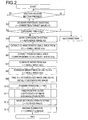
- Fig. 2 is a flow chart showing a flow of operations for motion blur detection and motion blur correction, in connection with Example 1, and
- Fig. 3 is a conceptual diagram showing part of the flow of operations. This flow of operations will now be described step by step with reference to Fig. 2 .
- step S3 the exposure time T1 with which the correction target image A1 was obtained is compared with a threshold value T TH and, if the exposure time T1 is smaller than the threshold value T TH , it is judged that the correction target image contains no (or an extremely small amount of) blur attributable to motion, and the flow shown in Fig. 2 is ended without performing motion blur correction.
- the threshold value T TH is, for example, the motion blur limit exposure time.
- the motion blur limit exposure time is the limit exposure time at which motion blur can be ignored, and is calculated from the reciprocal of the focal length f D .
- step S4 following the ordinary-exposure shooting, short-exposure shooting is performed, and the shot image obtained as a result is, as a reference image, stored in the memory.
- the reference image in Example 1 will henceforth be called the reference image A2.
- the correction target image A1 and the reference image A2 are obtained by consecutive shooting (that is, in consecutive frames), but the main control portion 13 controls the exposure control portion 18 shown in Fig. 1 such that the exposure time with which the reference image A2 is obtained is shorter than the exposure time T1.
- the exposure time of the reference image A2 is set at T1 / 4.
- the correction target image A1 and the reference image A2 have an equal image size.
- step S5 from the correction target image A1, a characteristic small area is extracted, and the image in the thus extracted small area is, as a small image A1a, stored in the memory.
- a characteristic small area denotes a rectangular area that is located in the extraction source image and that contains a comparatively large edge component (in other words, has high contrast); for example, by use of the Harris corner detector, a 128 x 128-pixel small area is extracted as a characteristic small area. In this way, a characteristic small area is selected based on the magnitude of the edge component (or the amount of contrast) in the image in that small area.
- step S6 from the reference image A2, a small area having the same coordinates as the small area extracted from the correction target image A1 is extracted, and the image in the small area extracted from the reference image A2 is, as a small image A2a, stored in the memory.
- the center coordinates of the small area extracted from the correction target image A1 (that is, the center coordinates in the correction target image A1) are equal to the center coordinates of the small area extracted from the reference image A2 (that is, the center coordinates in the reference image A2); moreover, since the correction target image A1 and the reference image A2 have an equal image size, the two small areas have an equal image size.
- the small image A2a is subjected to noise elimination.
- the small image A2a having undergone the noise elimination is taken as a small image A2b.
- the noise elimination here is achieved by filtering the small image A2a with a linear filter (such as a weighted averaging filter) or a non-linear filter (such as a median filter).
- step S8 the brightness level of the small image A2b is increased. Specifically, for example, brightness normalization is performed in which the brightness values of the individual pixels of the small image A2b are multiplied by a fixed value such that the brightness level of the small image A2b becomes equal to the brightness level of the small image A1a (such that the average brightness of the small image A2b becomes equal to the average brightness of the small image A1a).
- the small image A2b thus having its brightness level increased is taken as a small image A2c.
- step S9 With the thus obtained small images A1a and A2c taken as a convolved (degraded) image and an initially deconvolved (restored) image respectively (step S9), then, in step S10, Fourier iteration is executed to find an image convolution function.
- an initial deconvolved image (the initial value of a deconvolved image) needs to be given, and this initial deconvolved image is called the initially deconvolved image.
- the image convolution function is a point spread function (hereinafter called a PSF).
- a PSF point spread function
- An operator, or space filter, that is weighted so as to represent the locus described by an ideal point image on a shot image when the image-sensing apparatus 1 blurs is called a PSF, and is generally used as a mathematical model of motion blur. Since motion blur uniformly convolves (degrades) the entire shot image, the PSF found for the small image A1a can be used as the PSF for the entire correction target image A1.
- Fourier iteration is a method for restoring, from a convolved image - an image suffering degradation, a deconvolved image - an image having the degradation eliminated or reduced (see, for example, the following publication: G. R. Ayers and J. C. Dainty, "Iterative blind deconvolution method and its applications", OPTICS LETTERS, 1988, Vol. 13, No. 7, pp. 547-549 ).
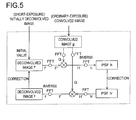
- Figs. 4 is a detailed flow chart of the processing in step S10 in Fig. 2 .
- Fig. 5 is a block diagram of the parts that execute Fourier iteration.
- step S101 the deconvolved image is represented by f, and the initially deconvolved image is taken as the deconvolved image f. That is, as the initial deconvolved image f, the above-mentioned initially deconvolved image (in Example 1, the small image A2c) is used.
- step S102 the convolved image (in Example 1, the small image A1a) is taken as g. Then, the convolved image g is Fourier-transformed, and the result is, as G, stored in the memory (step S103).
- f' and g are expressed as matrices each of an 128 ⁇ 128 array.
- step S110 the deconvolved image f' is Fourier-transformed to find F', and then, in step S111, H is calculated according to formula (1) below.
- H corresponds to the Fourier-transformed result of the PSF.
- F'* is the conjugate complex matrix of F'
- ⁇ is a constant.
- H G ⁇ F ⁇ *
- step S 112 H is inversely Fourier-transformed to obtain the PSF.
- the obtained PSF is taken as h.
- step S113 the PSF h is corrected according to the restricting condition given by formula (2a) below, and the result is further corrected according to the restricting condition given by formula (2b) below.
- the PSF h is expressed as a two-dimensional matrix, of which the elements are represented by h(x, y). Each element of the PSF should inherently take a value of 0 or more but 1 or less. Accordingly, in step S 113, whether or not each element of the PSF is 0 or more but 1 or less is checked and, while any element that is 0 or more but 1 or less is left intact, any element more than 1 is corrected to be equal to 1 and any element less than 0 is corrected to be equal to 0. This is the correction according to the restricting condition given by formula (2a). Then, the thus corrected PSF is normalized such that the sum of all its elements equals 1. This normalization is the correction according to the restricting condition given by formula (2b).
- step S114 the PSF h' is Fourier-transformed to find H', and then, in step S115, F is calculated according to formula (3) below.
- F corresponds to the Fourier-transformed result of the deconvolved image f.
- H'* is the conjugate complex matrix of H'.
- F G ⁇ H ⁇ *
- step S 116 F is inversely Fourier-transformed to obtain the deconvolved image.
- the thus obtained deconvolved image is taken as f.
- step S 117 the deconvolved image f is corrected according to the restricting condition given by formula (4) below, and the corrected deconvolved image is newly taken as f'.
- f x ⁇ y ⁇ 225 : f x ⁇ y > 225 f x ⁇ y : 0 ⁇ f x ⁇ y ⁇ 255 0 : f x ⁇ y ⁇ 0
- the deconvolved image f is expressed as a two-dimensional matrix, of which the elements are represented by f(x, y). Assume here that the value of each pixel of the convolved image and the deconvolved image is represented as a digital value of 0 to 255. Then, each element of the matrix representing the deconvolved image f (that is, the value of each pixel) should inherently take a value of 0 or more but 255 or less.
- step S 117 whether or not each element of the matrix representing the deconvolved image f is 0 or more but 255 or less is checked and, while any element that is 0 or more but 255 or less is left intact, any element more than 255 is corrected to be equal to 255 and any element less than 0 is corrected to be equal to 0. This is the correction according to the restricting condition given by formula (4).
- step S 118 whether or not a convergence condition is fulfilled is checked and thereby whether or not the iteration has converged is checked.
- the absolute value of the difference between the newest F' and the immediately previous F' is used as an index for the convergence check. If this index is equal to or less than a predetermined threshold value, it is judged that the convergence condition is fulfilled; otherwise, it is judged that the convergence condition is not fulfilled.
- the newest H' is inversely Fourier-transformed, and the result is taken as the definitive PSF. That is, the inversely Fourier-transformed result of the newest H' is the PSF eventually found in step S10 in Fig. 2 .
- the flow returns to step S 110 to repeat the operations in steps S110 to S 118. As the operations in steps S 110 to S 118 are repeated, the functions f, F', H, h, h', H', F, and f (see Fig. 5 ) are updated to be the newest one after another.
- any other index may be used.
- the absolute value of the difference between the newest H' and the immediately previous H' may be used as an index for the convergence check with reference to which to check whether or not the above-mentioned convergence condition is fulfilled.
- the amount of correction made in step S 113 according to formulae (2a) and (2b) above, or the amount of correction made in step S 117 according to formula (4) above may be used as the index for the convergence check with reference to which to check whether or not the above-mentioned convergence condition is fulfilled. This is because, as the iteration converges, those amounts of correction decrease.
- step S11 the elements of the inverse matrix of the PSF calculated in step S10 are found as the individual filter coefficients of the image deconvolution filter.
- This image deconvolution filter is a filter for obtaining the deconvolved image from the convolved image.
- the elements of the matrix expressed by formula (5) below which corresponds to part of the right side of formula (3) above, correspond to the individual filter coefficients of the image deconvolution filter, and therefore an intermediary result of the Fourier iteration calculation in step S 10 can be used intact.
- H'* and H' in formula (5) are H'* and H' as obtained immediately before the fulfillment of the convergence condition in step S 118 (that is, H'* and H' as definitively obtained).
- step S 12 the correction target image A1 is filtered with the image deconvolution filter to generate a filtered image in which the blur contained in the correction target image A1 has been eliminated or reduced.
- the filtered image may contain ringing ascribable to the filtering, and thus then, in step S 13, the ringing is eliminated to generate the definitive corrected image.
- the image-sensing portion 11 performs shooting sequentially at predetermined frame periods (for example, 1 / 60 seconds) and, in each frame, the main control portion 13 generates a through-display image from the output of the image-sensing portion 11, so that one through-display image after another thus obtained is displayed on the display portion 15 one after another on a constantly refreshed basis.
- the through-display image is an image for a moving image, and its image size is smaller than that of the correction target image, which is a still image.
- the correction target image is generated from the pixel signals of all the pixels in the effective image-sensing area of the image sensor provided in the image-sensing portion 11
- the through-display image is generated from the pixel signals of thinned-out part of the pixels in the effective image-sensing area.
- the correction target image is nothing but the shot image itself that is shot by ordinary exposure and recorded at the press of the shutter release button 17a, while the through-display image is a thinned-out image of the shot image of a given frame.
- Example 2 the through-display image based on the shot image of the frame immediately before or after the frame in which the correction target image is shot is used as a reference image.
- the following description deals with, as an example, a case where the through-display image of the frame immediately before the frame in which the correction target image is shot is used.
- Figs. 6 and 7 are referred to.
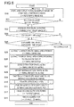
- Fig. 6 is a flow chart showing the flow of operations for motion blur detection and motion blur correction, in connection with Example 2, and
- Fig. 7 is a conceptual diagram showing part of the flow of operations. This flow of operations will now be described step by step with reference to Fig. 6 .
- a through-display image is generated in each frame so that one through-display image after another is stored in the memory on a constantly refreshed basis and displayed on the display portion 15 on a constantly refreshed basis (step S20).
- the shutter release button 17a is pressed, ordinary-exposure shooting is performed, and the correction target image generated as a result is stored (steps S21 and S22).
- the correction target image in Example 2 will henceforth be called the correction target image B1.
- the through-display image present in the memory at this point is that obtained in the shooting of the frame immediately before the frame in which the correction target image B1 is shot, and this through-display image will henceforth be called the reference image B3.
- step S23 the exposure time T1 with which the correction target image B I was obtained is compared with a threshold value T TH . If the exposure time T1 is smaller than the threshold value T TH (which is, for example, the reciprocal of the focal length f D ), it is judged that the correction target image contains no (or an extremely small amount of) blur attributable to motion, and the flow shown in Fig. 6 is ended without performing motion blur correction.
- T TH which is, for example, the reciprocal of the focal length f D
- step S24 the exposure time T1 is compared with the exposure time T3 with which the reference image B3 was obtained. If T1 ⁇ T3, it is judged that the reference image B3 has more motion blur, and the flow shown in Fig. 6 is ended without performing motion blur correction. If T1 > T3, then, in step S25, by use of the Harris corner detector or the like, a characteristic small area is extracted from the reference image B3, and the image in the thus extracted small area is, as a small image B3a, stored in the memory.
- the significance of and the method for extracting a characteristic small area are the same as described in connection with Example 1.
- step S26 a small area corresponding to the coordinates of the small image B3a is extracted from the correction target image B1. Then, the image in the small area thus extracted from the correction target image B 1 is reduced in the image size ratio of the correction target image B 1 to the reference image B3, and the resulting image is, as a small image B1a, stored in the memory. That is, when the small image B1a is generated, its image size is normalized such that the small images B1a and B3a have an equal image size.
- the center coordinates of the small area extracted from the correction target image B 1 coincide with the center coordinates of the small area extracted from the reference image B3 (that is, the center coordinates in the reference image B3).
- the correction target image B1 and the reference image B3 have different image sizes, and accordingly the image sizes of the two small areas differ in the image size ratio of the correction target image B1 to the reference image B3.
- the image size ratio of the small area extracted from the correction target image B 1 to the small area extracted from the reference image B3 is made equal to the image size ratio of the correction target image B1 to the reference image B3.
- the small image B1a is obtained.
- step S27 the small images B1a and B3a are subjected to edge extraction to obtain small images B1b and B3b.
- edge extraction For example, an arbitrary edge detection operator is applied to each pixel of the small image B1a to generate an extracted-edge image of the small image B1a, and this extracted-edge image is taken as the small area B1b. The same is done with the small image B3b.
- step S28 the small images B1b and B3b are subjected to brightness normalization. Specifically, the brightness values of the individual pixels of the small image B1b or B3b or both are multiplied by a fixed value such that the small images B1b and B3b have an equal brightness level (such that the average brightness of the small image B1b becomes equal to the average brightness of the small image B3b).
- the small images B1b and B3b having undergone the brightness normalization are taken as small images B1c and B3c.
- the through-display image taken as the reference image B3 is an image for a moving image, and is therefore obtained through image processing for a moving image - after being so processed as to have a color balance suitable for a moving image.
- the correction target image B 1 is a still image shot at the press of the shutter release button 17a, and is therefore obtained through image processing for a still image. Due to the differences between the two types of image processing, the small images B1a and B3a, even with the same subject, have different color balances. This difference can be eliminated by edge extraction, and this is the reason that edge extraction is performed in step S27.
- Edge extraction also largely eliminates the difference in brightness between the correction target image B1 and the reference image B3, and thus helps reduce the effect of a difference in brightness (that is, it helps enhance the accuracy of blur detection); it however does not completely eliminate it, and therefore, thereafter, in step S28, brightness normalization is performed.
- step S29 With the thus obtained small images B1c and B3c taken as a convolved image and an initially deconvolved image respectively (step S29), the flow proceeds to step S 10 to perform the operations in steps S 10, S11, S 12, and S 13 sequentially.
- steps S10 to S 13 are the same as in Example 1. The difference is that, since the individual filter coefficients of the image deconvolution filter obtained through steps S 10 and S11 (and the PSF obtained through step S10) are adapted to the image size of a moving image, these are here re-adapted to the image size of a still image by vertical and horizontal enlargement.
- the image size ratio of the through-display image to the correction target image is 3 : 5 and in addition the size of the image deconvolution filter obtained through steps S 10 and S11 is 3 x 3
- the individual filter coefficients of an image deconvolution filter having a size of 5 x 5 as indicated by 102 in Fig. 8 are generated.
- the individual filter coefficients of the 5 x 5-size image deconvolution filter are taken as the individual filter coefficients obtained in step S11.
- those filter coefficients which are interpolated by vertical and horizontal enlargement are given the value of 0; instead, they may be given values calculated by linear interpolation or the like.
- step S12 the correction target image B 1 is filtered with this image deconvolution filter to generate a filtered image in which the blur contained in the correction target image B1 has been eliminated or reduced.
- the filtered image may contain ringing ascribable to the filtering, and thus then, in step S 13, the ringing is eliminated to generate the definitive corrected image.
- Fig. 9 is a flow chart showing the flow of operations for motion blur detection and motion blur correction, in connection with Example 3, and Fig. 10 is a conceptual diagram showing part of the flow of operations. This flow of operations will now be described step by step with reference to Fig. 9 .
- a through-display image is generated in each frame so that one through-display image after another is stored in the memory on a constantly refreshed basis and displayed on the display portion 15 on a constantly refreshed basis (step S30).
- the shutter release button 17a is pressed, ordinary-exposure shooting is performed, and the correction target image generated as a result is stored (steps S31 and S32).
- the correction target image in Example 3 will henceforth be called the correction target image C1.
- the through-display image present in the memory at this point is that obtained in the shooting of the frame immediately before the frame in which the correction target image C 1 is shot, and this through-display image will henceforth be called the reference image C3.
- step S33 the exposure time T1 with which the correction target image C1 was obtained is compared with a threshold value T TH . If the exposure time T1 is smaller than the threshold value T TH (which is, for example, the reciprocal of the focal length f D ), it is judged that the correction target image contains no (or an extremely small amount of) blur attributable to motion, and the flow shown in Fig. 9 is ended without performing motion blur correction.
- T TH which is, for example, the reciprocal of the focal length f D
- the exposure time T1 is compared with the exposure time T3 with which the reference image C3 was obtained. If T1 ⁇ T3, it is judged that the reference image C3 has more motion blur, and thereafter motion blur detection and motion blur correction similar to those performed in Example 1 are performed (that is, operations similar to those in steps S4 to S 13 in Fig. 2 are performed). By contrast, if T1 > T3, then, in step S34, following the ordinary-exposure shooting, short-exposure shooting is performed, and the shot image obtained as a result is, as a reference image C2, stored in the memory. In Fig. 9 , the operation of comparing T1 and T3 is omitted, and the following description deals with a case where T1 > T3.
- the correction target image C1 and the reference image C2 are obtained by consecutive shooting (that is, in consecutive frames), but the main control portion 13 controls the exposure control portion 18 shown in Fig. 1 such that the exposure time with which the reference image C2 is obtained is shorter than the exposure time T1.
- the exposure time of the reference image C2 is set at T3 /4.
- the correction target image C1 and the reference image C2 have an equal image size.
- step S35 by use of the Harris corner detector or the like, a characteristic small area is extracted from the reference image C3, and the image in the thus extracted small area is, as a small image C3a, stored in the memory.
- the significance of and the method for extracting a characteristic small area are the same as described in connection with Example 1 .
- step S36 a small area corresponding to the coordinates of the small image C3a is extracted from the correction target image C1. Then, the image in the small area thus extracted from the correction target image C1 is reduced in the image size ratio of the correction target image C1 to the reference image C3, and the resulting image is, as a small image C1a, stored in the memory. That is, when the small image C1a is generated, its image size is normalized such that the small images C1a and C3a have an equal image size. Likewise, a small area corresponding to the coordinates of the small image C3a is extracted from the reference image C2.
- the image in the small area thus extracted from the reference image C2 is reduced in the image size ratio of the reference image C2 to the reference image C3, and the resulting image is, as a small image C2a, stored in the memory.
- the method for obtaining the small image C1a (or the small image C2a) from the correction target image C1 (or the reference image C2) is the same as the method, described in connection with Example 2, for obtaining the small image B1a from the correction target image B 1 (step S26 in Fig. 6 ).
- step S37 the small image C2a is subjected to brightness normalization with respect to the small image C3a. That is, the brightness values of the individual pixels of the small image C2a are multiplied by a fixed value such that the small images C3a and C2a have an equal brightness level (such that the average brightness of the small image C3a becomes equal to the average brightness of the small image C2a).
- the small image C2a having undergone the brightness normalization is taken as a small image C2b.
- step S38 the differential image between the small images C3a and C2b is generated.
- the differential image pixels take a value other than 0 only where the small images C3a and C2b differ from each other.
- the values of the individual pixels of the differential image taken as weighting coefficients, the small images C3a and C2b are subjected to weighted addition to generate a small image C4a.
- I 4 (p, q) is given by formula (6) below, where k is a constant and p and q are horizontal and vertical coordinates, respectively, in the relevant differential or small image.
- I 4 p ⁇ q k ⁇ I D p ⁇ q ⁇ I 2 p ⁇ q + 1 - k ⁇ I D p ⁇ q ⁇ I 3 p ⁇ q
- the small image C4a is used as an image based on which to calculate the PSF corresponding to the blur in the correction target image C1.
- To obtain a good PSF it is necessary to maintain an edge part appropriately in the small image C4a.
- the higher the S/N ratio of the small image C4a the better the PSF obtained.
- adding up a plurality of images leads to a higher S/N ratio; this is the reason that the small images C3a and C2b are added up to generate the small image C4a. If, however, the addition causes the edge part to blur, it is not possible to obtain a good PSF.
- the small image C4a is generated through weighted addition according to the pixel values of the differential image.
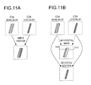
- the exposure time of the small image C3a is longer than the exposure time of the small image C2b, as shown in Fig. 11A , when the same edge image is shot, more blur occurs in the former than in the latter. Accordingly, if the two small images are simply added up, as shown in Fig. 11A , the edge part blurs; by contrast, as shown in Fig.
- the edge part is maintained comparatively well.
- I D (p, q) are larger, giving more weight to the small image C2b, with the result that the small image C4a reflects less of the large edge part convolution in the small image C3a.
- the non-different part 111 more weight is given to the small image C3a, of which the exposure time is comparatively long, and this helps increase the S/N ratio (reduce noise).
- step S39 the small image C4a is subjected to brightness normalization with respect to the small image C1a. That is, the brightness values of the individual pixels of the small image C4a are multiplied by a fixed value such that the small images C1a and C4a have an equal brightness level (such that the average brightness of the small image C1a becomes equal to the average brightness of the small image C4a).
- the small image C4a having undergone the brightness normalization is taken as a small image C4b.
- step S40 With the thus obtained small images C1a and C4b taken as a convolved image and an initially deconvolved image respectively (step S40), the flow proceeds to step S10 to perform the operations in steps S 10, S 11, S 12, and S 13 sequentially.
- steps S10 to S 13 are the same as in Example 1.
- the difference is that, since the individual filter coefficients of the image deconvolution filter obtained through steps S10 and S11 (and the PSF obtained through step S10) are adapted to the image size of a moving image, these are here re-adapted to the image size of a still image by vertical and horizontal enlargement.
- the vertical and horizontal enlargement here is the same as described in connection with Example 2.
- step S12 the correction target image C 1 is filtered with this image deconvolution filter to generate a filtered image in which the blur contained in the correction target image C1 has been eliminated or reduced.
- the filtered image may contain ringing ascribable to the filtering, and thus then, in step S 13, the ringing is eliminated to generate the definitive corrected image.
- Figs. 12 and 13 are referred to.
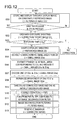
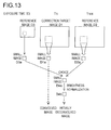
- Fig. 12 is a flow chart showing the flow of operations for motion blur detection and motion blur correction, in connection with Example 4, and
- Fig. 13 is a conceptual diagram showing part of the flow of operations. This flow of operations will now be described step by step with reference to Fig. 12 .
- Example 4 first, the operations in steps S50 to S56 are performed.
- the operations in steps S50 to S56 are the same as those in steps S30 to S36 (see Fig. 9 ) in Example 3, and therefore no overlapping description will be repeated.
- the correction target image C1 and the reference images C2 and C3 in Example 3 are read as a correction target image D 1 and reference images D2 and D3 in Example 4.
- the exposure time of the reference image D2 is set at, for example, T1 /4.
- step S50 to S56 small images D1a, D2a, and D3a based on the correction target image D1 and the reference images D2 and D3 are obtained, and then the flow proceeds to step S57.
- step S57 one of the small images D2a and D3a is chosen as a small image D4a.
- the choice here is made according to one or more of various indices.
- the edge intensity of the small image D2a is compared with that of the small image D3a, and whichever has the higher edge intensity is chosen as the small image D4a.
- the small image D4a will serve as the basis of the initially deconvolved image for Fourier iteration. This is because it is believed that, the higher the edge intensity of an image is, the less its edge part is degraded and thus the more suitable it is as the initially deconvolved image.
- a predetermined edge extraction operator is applied to each pixel of the small image D2a to generate an extracted-edge image of the small image D2a, and the sum of the all pixel values of this extracted-edge image is taken as the edge intensity of the small image D2a.
- the edge intensity of the small image D3a is calculated likewise.
- the exposure time of the reference image D2 is compared with that of the reference image D3, and whichever has the shorter exposure time is chosen as the small image D4a.
- selection information external information
- one of the small images D2a and D3a is chosen as the small image D4a. The choice may be made according to an index value representing the combination of the above-mentioned edge intensity, exposure time, and selection information.
- step S58 the small image D4a is subjected to brightness normalization with respect to the small image D1a. That is, the brightness values of the individual pixels of the small image D4a are multiplied by a fixed value such that the small images D1a and D4a have an equal brightness level (such that the average brightness of the small image D1a becomes equal to the average brightness of the small image D4a).
- the small image D4a having undergone the brightness normalization is taken as a small image D4b.
- step S59 With the thus obtained small images D1a and D4b taken as a convolved image and an initially deconvolved image respectively (step S59), the flow proceeds to step S10 to perform the operations in steps S 10, S 11, S 12, and S 13 sequentially.
- steps S10 to S 13 are the same as in Example 1.
- the difference is that, since the individual filter coefficients of the image deconvolution filter obtained through steps S10 and S 11 (and the PSF obtained through step S10) are adapted to the image size of a moving image, these are here re-adapted to the image size of a still image by vertical and horizontal enlargement.
- the vertical and horizontal enlargement here is the same as described in connection with Example 2.
- step S12 the correction target image D1 is filtered with this image deconvolution filter to generate a filtered image in which the blur contained in the correction target image D1 has been eliminated or reduced.
- the filtered image may contain ringing ascribable to the filtering, and thus then, in step S 13, the ringing is eliminated to generate the definitive corrected image.
- Example 5 focuses on the configuration for achieving the motion blur detection and motion blur correction described in connection with Examples 1 to 4.
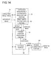
- Fig. 14 is a block diagram showing the configuration.
- the correction target image mentioned in Example 5 is the correction target image (A1, B1, C1, or D1) in Examples 1 to 4, and the reference image mentioned in Example 5 is the reference image(s) (A2, B3, C2 and C3, or D2 and D3) in Examples 1 to 4.
- a memory 31 is realized with the internal memory 14 shown in Fig. 1 , or is provided within the motion blur detection/correction portion 19.
- a convolved image/initially deconvolved image setting portion 32, a Fourier iteration processing portion 33, a filtering portion 34, and a ringing elimination portion 35 are provided in the motion blur detection/correction portion 19.
- the memory 31 stores the correction target image and the reference image. Based on what is recorded in the memory 31, the convolved image/initially deconvolved image setting portion 32 sets a convolved image and an initially deconvolved image by any of the methods described in connection with Examples 1 to 4, and feeds them to the Fourier iteration processing portion 33. For example, in a case where Example 1 is applied, the small images A1a and A2c obtained through the operations in steps S1 to S8 in Fig. 2 are, as a convolved image and an initially deconvolved image respectively, fed to the Fourier iteration processing portion 33.
- the convolved image/initially deconvolved image setting portion 32 includes a small image extraction portion 36, which extracts from the correction target image and the reference image small images (A1a and A2a in Fig. 3 , C1a, C2a, and C3a in Fig. 10 , etc.) that will serve as the bases of the convolved image and the initially deconvolved image.
- a small image extraction portion 36 which extracts from the correction target image and the reference image small images (A1a and A2a in Fig. 3 , C1a, C2a, and C3a in Fig. 10 , etc.) that will serve as the bases of the convolved image and the initially deconvolved image.
- the Fourier iteration processing portion 33 executes the Fourier iteration previously described with reference to Fig. 4 etc.
- the image deconvolution filter itself is implemented in the filtering portion 34, and the Fourier iteration processing portion 33 calculates the individual filter coefficients of the image deconvolution filter by performing the operations in steps S10 and S11 in Fig. 2 etc.
- the filtering portion 34 applies the image deconvolution filter having the calculated individual filter coefficients to each pixel of the correction target image and thereby filters the correction target image to generate a filtered image.
- the size of the image deconvolution filter is smaller than that of the correction target image, but since it is believed that motion blur uniformly degrades the entire image, applying the image deconvolution filter to the entire correction target image eliminates the blur in the entire correction target image.
- the ringing elimination portion 35 performs weighted averaging between the thus generated filtered image and the correction target image to generate a definitive corrected image. For example, the weighted averaging is performed pixel by pixel, and the ratio in which the weighted averaging is performed for each pixel is determined according to the edge intensity at that pixel in the correction target image.
- the blur contained in the correction target image has been eliminated or reduced, and the ringing ascribable to the filtering has also been eliminated or reduced. Since the filtered image generated by the filtering portion 34 already has the blur eliminated or removed, it can be regarded as a corrected image on its own.
- the reference image though lower in brightness, contains a smaller amount of blur.
- its edge component is close to that of an image containing no blur.
- the deconvolved image (f) grows closer and closer to an image containing minimal blur.
- the initially deconvolved image itself is already close to an image containing no blur, convergence takes less time than in cases in which, as conventionally practiced, a random image or a convolved image is taken as the initially deconvolved image (at shortest, convergence is achieved with a single loop).
- the processing time for the generation of motion blur information a PSF, or the filter coefficients of an image deconvolution filter
- the processing time for motion blur correction are reduced.
- the initially deconvolved image is remote from the image to which it should converge, it is highly likely that it will converge to a local solution (an image different from the image to which it should converge)
- setting the initially deconvolved image as described above makes it less likely that it will converge to a local solution (that is, makes failure of motion blur correction less likely).
- motion blur information (a PSF, or the filter coefficients of an image deconvolution filter) is created from the image data in the small area, and then the created motion blur information is applied to the entire image.
- PSF the filter coefficients of an image deconvolution filter
- a characteristic small area containing a large edge component is automatically extracted.
- An increase in the edge component in the image based on which to calculate a PSF signifies an increase in the proportion of the signal component to the noise component.
- extracting a characteristic small area helps reduce the effect of noise, and thus makes more accurate detection of motion blur information possible.
- Example 2 there is no need to perform shooting dedicated to the acquisition of a reference image; in Examples 1, 3, and 4, it is necessary to perform shooting dedicated to the acquisition of a reference image (short-exposure shooting) only once. Thus, almost no increase in load during shooting is involved. Moreover, needless to say, performing motion blur detection and motion blur correction without the use of an angular velocity sensor or the like helps reduce the cost of the image-sensing apparatus 1.
- a function H representing a PSF in the frequency domain is found, and this function H is then converted by an inverse Fourier transform to a function on the space domain, namely a PSF h.
- This PSF h is then corrected according to a predetermined restricting condition to find a corrected PSF h'.
- the correction of the PSF here will henceforth be called the "first type of correction”.
- the PSF h' is then converted by a Fourier transform back into the frequency domain to find a function H', and from the functions H' and G, a function F is found, which represents the deconvolved image in the frequency domain.
- This function F is then converted by inverse Fourier transform to find a deconvolved image f on the space domain.
- This deconvolved image f is then corrected according to a predetermined restricting condition to find a corrected deconvolved image f.
- the correction of the deconvolved image here will henceforth be called the "second type of correction".
- step S 118 in Fig. 4 the above processing is repeated on the corrected deconvolved image f; moreover, in view of the fact that, as the iteration converges, the amounts of correction decrease, the check of whether or not the convergence condition is fulfilled may be made based on the amount of correction made in step S 113, which corresponds to the first type of correction, or the amount of correction made in step S 117, which corresponds to the second type of correction.
- a reference amount of correction is set beforehand, and the amount of correction in step S 113 or S 117 is compared with it so that, if the former is smaller than the latter, it is judged that the convergence condition is fulfilled.
- the reference amount of correction is set sufficiently large, the operations in steps S110 to S117 are not repeated. That is, in that case, the PSF h' obtained through a single session of the first type of correction is taken as the definitive PSF that is to be found in step S10 in Fig. 2 etc. In this way, even when the processing shown in Fig. 4 is adopted, the first and second types of correction are not always repeated.
- step S 118 the operations in steps S 115 to S 117 are also omitted.
- the reference image A2, C2, or D2 is obtained by short-exposure shooting immediately after the ordinary-exposure shooting by which the correction target image is obtained.
- the reference image may be obtained by short-exposure shooting immediately before the ordinary-exposure shooting of the correction target image.
- the through-display image of the frame immediately after the frame in which the correction target image is shot is taken.
- each small image in the process of generating from given small images a convolved image and an initially deconvolved image for Fourier iteration, each small image is subjected to one or more of the following types of processing: noise elimination; brightness normalization; edge extraction, and image size normalization (see Figs. 3 , 7 , 10 , and 13 ).
- the specific manners in which these different types of processing are applied in respective Examples are merely examples, and may be modified in various ways.
- each small area may be subjected to all of the four types of processing (although performing image size normalization in Example 1 is meaningless).
- the AF evaluation value calculated in autofocus control may be used for the extraction.
- the autofocus control here employs a TTL (through-the-lens) contrast detection method.
- the image-sensing apparatus 1 is provided with an AF evaluation portion (unillustrated).
- the AF evaluation portion divides a shot image (or a through-display image) into a plurality of sections and calculates, for each of these sections, an AF evaluation value commensurate with the amount of contrast in the image there.
- the main control portion 13 shown in Fig. 1 controls the position of the focus lens of the image-sensing portion 11 by hill-climbing control such that the AF evaluation value takes the largest (or a maximal) value, so that an optical image of the subject is focused on the image-sensing surface of the image sensor.
- the AF evaluation values for the individual sections of the extraction source image are referred to. For example, of all the AF evaluation values for the individual sections of the extraction source image, the largest one is identified, and the section (or an area determined relative to it) corresponding to the largest AF evaluation value is extracted as the characteristic small area. Since the AF evaluation value increases as the amount of contrast (or the edge component) in the section increases, this can be exploited to extract a small area containing a comparatively large edge component as a characteristic small area.
- the image-sensing apparatus 1 shown in Fig. 1 can be realized in hardware or in a combination of hardware and software.
- the functions of the components shown in Fig. 14 can be realized in hardware, in software, or in a combination of hardware and software, and these functions can be realized on an apparatus (such as a computer) external to the image-sensing apparatus 1.
- the convolved image/initially deconvolved image setting portion 32 and the Fourier iteration processing portion 33 form a blur detection apparatus, and a blur correction apparatus is formed by, among other components, the filtering portion 34 and the ringing elimination portion 35. From this blur correction apparatus, the ringing elimination portion 35 may be omitted.
- the blur correction apparatus may also be regarded as including the blur detection apparatus.
- the blur detection apparatus may include the memory 31 (holder).
- the motion blur detection/correction portion 19 functions as a blur detection apparatus and also as a blur correction apparatus.
- the Fourier iteration processing portion 33 on its own, or the convolved image/initially deconvolved image setting portion 32 and the Fourier iteration processing portion 33 combined together, function as means for generating motion blur information (a PSF, or the filter coefficients of an image deconvolution filter).
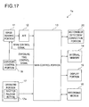
- FIG. 17 is an overall block diagram of the image-sensing apparatus 1a of the second embodiment.
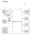
- the image-sensing apparatus 1a is formed of components identified by reference signs 11 to 18 and 20. That is, the image-sensing apparatus 1a is formed by replacing the motion blur detection/correction portion 19 in the image-sensing apparatus 1 with a motion blur detection/correction portion 20, and the two image-sensing apparatuses are otherwise the same. Accordingly, no overlapping description of the same components will be repeated.
- the image-sensing apparatus 1a when the shutter release button 17a is pressed in shooting mode, ordinary-exposure shooting is performed, and the shot image obtained as a result is, as a correction target image E1, stored in the memory.
- the exposure time (the length of the exposure time) with which the correction target image E1 is obtained is represented by T1.
- short-exposure shooting is performed, and the shot image obtained as a result is, as a reference image E2, stored in the memory.
- the correction target image E1 and the reference image E2 are obtained by consecutive shooting (that is, in consecutive frames), but the main control portion 13 controls the image-sensing portion 11 via the exposure control portion 18 such that the exposure time with which the reference image E2 is obtained is shorter than the exposure time T1.
- the exposure time of the reference image E2 is set at T1 / 4.
- the correction target image E1 and the reference image E2 have an equal image size.
- the exposure time T1 may be compared with the threshold value T TH (the motion blur limit exposure time), mentioned in connection with the first embodiment, so that, if the former is smaller than the latter, it is judged that the correction target image contains no (or an extremely small amount of) blur attributable to motion, and no motion blur correction is performed. In that case, it is not necessary to perform the short-exposure shooting for obtaining the reference image E2.
- T TH the motion blur limit exposure time
- a characteristic small area is extracted from the reference image E2, and a small area corresponding to the small area extracted from the reference image E2 is extracted from the correction target image E1.
- the extracted small areas each have a size of, for example, 128 x 128 pixels.
- the significance of and the method for extracting a characteristic small area are the same as described in connection with the first embodiment.
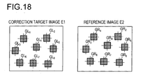
- a plurality of characteristic small areas are extracted from the reference image E2. Accordingly, as many small areas are extracted from the correction target image E1.
- the small images GR i and GL i have an equal image size (that is, the small images GR 1 to GR 8 and the small images GL 1 to GL 8 have an equal image size).
- the small areas are extracted such that the center coordinates of each small image GR i (the center coordinates in the reference image E2) extracted from the reference image E2 are equal to the center coordinates of the corresponding small image GL i (the center coordinates in the correction target image E1) extracted from the correction target image E1.
- template matching or the like may be used to search for corresponding small areas (this applies equally to the first embodiment). Specifically, for example, with each small image GR i taken as a template, by the well-known template matching, a small area that is most similar to the template is searched for in the correction target image E1, and the image in the small area found as a result is taken as the small image GL i .
- Fig. 19 is an enlarged view of small images GL 1 and GR 1 .
- a high-brightness part is shown white, and a low-brightness part is shown black.
- the small images GL 1 and GR 1 contain edges, where brightness sharply changes in the horizontal and vertical directions.
- the image-sensing apparatus 1a was acted upon by motion (such as camera shake) in the horizontal direction.
- motion such as camera shake
- the small image GR 1 is subjected to edge extraction using an arbitrary edge detection operator to obtain an extracted-edge image ER 1 as shown in Fig. 20 .
- an extracted-edge image ER 1 shown in Fig. 20 a high-edge-intensity part is shown white, and a low-edge-intensity part is shown black.
- the part along the rectilinear edges in the small image GR 1 appears as a high-edge-intensity part in the extracted-edge image ER 1 .
- the extracted-edge image ER 1 is then subjected to the well-known Huff conversion to extract straight lines along the edges.
- the extracted lines as overlaid on the small image GR 1 is shown in the right part of Fig. 20 .
- extracted from the small image GR 1 are: a straight line HR 11 extending in the vertical direction; and a straight line HR 12 extending in the horizontal direction.
- straight lines HL 11 and HL 12 corresponding to the straight lines HR 11 and HR 12 are extracted from the small image GL 1 .
- Fig. 21 shows the extracted straight lines HL 11 and HL 12 as overlaid on the small image GL 1 .
- Fig. 21 also shows the small image GR 1 with the straight lines HR 11 and HR 12 overlaid on it.
- the mutually corresponding straight lines run in the same direction; specifically, the straight lines HL 11 and HR 11 extend in the same direction, and so do the straight lines HL 12 and HR 12 .
- the distribution of brightness values in the direction perpendicular to each of those straight lines is found, in each of the small images.
- the straight line HL 11 and the straight line HR 11 are parallel to the vertical direction of the images
- the straight line HL 12 and the straight line HR 12 are parallel to the horizontal direction of the image.
- the distribution of brightness values in the horizontal direction of the images is found and, with respect to the straight line HL 12 and the straight line HR 12 , the distribution of brightness values in the vertical direction of the images is found.
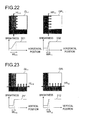
- the solid-line arrows shown in the small image GL 1 indicate how brightness values are scanned in the direction perpendicular to the straight line HL 11 . Since the direction perpendicular to the straight line HL 11 is horizontal, while scanning is performed from left to right starting at a given point at the left end of the small image GL 1 , the brightness value of one pixel after another in the small image GL 1 is acquired, so that eventually the distribution of brightness values in the direction perpendicular to the straight line HL 11 is found. Here, the scanning is performed across the part where the edge corresponding to the straight line HL 11 lies.
- the distribution of brightness values is found where the slope of brightness values is sharp. Accordingly, no scanning is performed along the broken-line arrows in Fig. 22 (the same applies in Fig. 23 , which will be described later).
- a distribution found with respect to a single line is greatly affected by the noise component; thus, similar distributions are found along a plurality of lines in the small image GL 1 , and the average of the found distributions is taken as the distribution 201 to be definitively found with respect to the straight line HL 11 .
- the distribution with respect to the straight line HR 11 is found likewise.
- the solid-line arrows shown in the small image GR 1 indicate how brightness values are scanned in the direction perpendicular to the straight line HR 11 . Since the direction perpendicular to the straight line HR 11 is horizontal, while scanning is performed from left to right starting at a given point at the left end of the small image GR 1 , the brightness value of one pixel after another in the small image GR 1 is acquired, so that eventually the distribution of brightness values in the direction perpendicular to the straight line HR 11 is found. Here, the scanning is performed across the part where the edge corresponding to the straight line HR 11 lies. That is, the distribution of brightness values is found where the slope of brightness values is sharp.
- the horizontal axis represents the horizontal position of pixels
- the vertical axis represents the brightness value.
- the brightness value sharply changes across the edge part extending in the vertical direction of the images.
- the change of the brightness value is comparatively gentle due to the motion during the exposure period.
- the edge part in the small image GL 1 that corresponds to the straight line HL 11 the number of pixels in the horizontal direction that are scanned after the brightness value starts to change until it stops changing is represented by WL 11 ; in the edge part in the small image GR 1 that corresponds to the straight line HR 11 , the number of pixels in the horizontal direction that are scanned after the brightness value starts to change until it stops changing is represented by WR 11 .
- the thus found WL 11 and WR 11 are called the edge widths. In the example under discussion, "WL 11 > WR 11 ".
- the difference between the edge widths "WL 11 - WR 11 " is regarded as a value representing, in terms of number of pixels, the amount of motion blur that occurred in the horizontal direction during the exposure period of the correction target image E1.
- edge widths as mentioned above are found also for the straight lines HL 12 and HR 12 extracted from the small images GL 1 and GR 1 .
- the solid-line arrows shown in the small image GL 1 indicate how brightness values are scanned in the direction perpendicular to the straight line HL 12 . While scanning is performed in the vertical direction so as to cross the part where the edge corresponding to the straight line HL 12 lies, the brightness value of one pixel after another in the small image GL 1 is acquired, so that eventually the distribution of brightness values in the direction perpendicular to the straight line HL 12 is found. The scanning is performed along a plurality of lines (in the case under discussion, a vertical line), and the average of the found distributions is taken as the distribution 211 to be definitively found with respect to the straight line HL 12 . In Fig.
- the solid-line arrows shown in the small image GR 1 indicate how brightness values are scanned in the direction perpendicular to the straight line HR 12 . While scanning is performed in the vertical direction so as to cross the part where the edge corresponding to the straight line HR 12 lies, the brightness value of one pixel after another in the small image GR 1 is acquired, so that eventually the distribution of brightness values in the direction perpendicular to the straight line HR 12 is found. The scanning is performed along a plurality of lines (in the case under discussion, a vertical line), and the average of the found distributions is taken as the distribution 212 to be definitively found with respect to the straight line HR 12 .
- edge widths WL 12 and WR 12 are found.
- the edge width WL 12 represents the number of pixels in the vertical direction that are scanned, in the edge part in the small image GL 1 that corresponds to the straight line HL 12 , after the brightness value starts to change until it stops changing;
- the edge width WR 12 represents the number of pixels in the vertical direction that are scanned, in the edge part in the small image GR 1 that corresponds to the straight line HR 12 , after the brightness value starts to change until it stops changing.
- the edge widths and their differences are found also with respect to the other small images GL 2 to GL 8 and GR 2 to GR 8 .
- the number of a given small image is represented by the variable i and the number of a given straight line is represented by the variable j (i and j are integers)
- the straight lines HL ij and HR ij are extracted from the small images GL i and GR i , and then the edge widths WL ij and WR ij with respect to the straight lines HL ij and HR jj are found.
- D ij WL ij - WR ij .
- the pair of straight lines corresponding to the largest of the differences D ij thus found is identified as the pair of straight lines for motion blur detection and, from the edge width difference and the direction of those straight lines corresponding to this pair, the PSF with respect to the entire correction target image E1 is found.
- the pair of straight lines HL 11 and HR 11 is identified as the one for motion blur detection, and the difference D 11 corresponding to the straight lines HL 11 and HR 11 is substituted in the variable D MAX representing the largest difference.
- a smoothing function for smoothing the image in the direction perpendicular to the straight line HL 11 is created. As shown in Fig. 24 , this smoothing function is expressed as a space filter 220 having a tap number (filter size) of D MAX in the direction perpendicular to the straight line HL 11 .
- the space filter shown in Fig. 24 has a filter size of 5 x 5; it gives a filter coefficient of 1 only to each of the elements in the horizontally middle row, and gives a filter coefficient of 0 to the other elements.
- normalization is performed such that the sum of all the filter coefficients equals 1.
- the motion blur detection/correction portion 20 corrects the motion blur in the correction target image E1.
- the PSF found as described above works well on the assumption that the direction and speed of the motion that acted upon the image-sensing apparatus 1a during the exposure period of the correction target image E1 is fixed. If this assumption is true, and the above smoothing function accurately represents the PSF of the correction target image E1, then, by subjecting an ideal image containing no blur to space filtering using the space filter 220, it is possible to obtain an image equivalent to the correction target image E1.
- Fig. 25 is a flow chart showing the flow of operations for motion blur detection, including the operations for the above processing. The operations in steps S151 to S155 are performed by the motion blur detection/correction portion 20.
- step S151 After the correction target image E1 and the reference image E2 are acquired, in step S151, a plurality of characteristic small areas are extracted from the reference image E2, and the images in those small areas are, as small images GR i , stored in the memory.
- step S 152 small areas respectively corresponding to the small images GR i are extracted from the correction target image E1, and the images in the small areas extracted from the correction target image E1 are, as small images GL i , stored in the memory.
- the memory are present, for example, small images GL 1 to GL 8 and GR 1 to GR 8 as shown in Fig. 18 .
- step S153 a loop for the variable i is executed, and this loop includes an internal loop for the variable j.
- step S153 from a small image GR i , an extracted-edge image ER i is generated, and then, from the extracted-edge image ER i , one or more straight lines HR ij are extracted, and then straight lines HL ij corresponding to the straight lines HR ij are extracted from a small image GL i .
- step S153 the same operations are performed for each of the values that the variable i can take and for each of the values that the variable j can take. As a result, when the flow proceeds from step S153 to step S 154, the differences D ij for all the combinations of i and j have been calculated.
- step S151 For example, in a case where, in step S151, eight small areas are extracted and thus small images GR 1 to GR 8 are generated and then two straight lines are extracted from each of the small images GR 1 to GR 8 are extracted, a total of 16 edge width differences D ij are found (here, i is an integer of 1 or more but 8 or less, and j is 1 or 2).
- step S154 the largest D MAX of all the edge width differences D ij found in step S 153 is identified, and the pair of straight lines corresponding to the largest difference D MAX is identified as the pair of straight lines for motion blur detection.
- motion blur correction proceeds through the same operations as described in connection with the first embodiment. Specifically, the motion blur detection/correction portion 20 finds, as the filter coefficients of an image deconvolution filter, the individual elements of the inverse matrix of the PSF found in step S 155, and then, with the image deconvolution filter having those filter coefficients, filters the entire correction target image E1. Then, the image having undergone the filtering, or the image having further undergone ringing elimination, is taken as the definitive corrected image. This corrected image is one in which the blur contained in the correction target image E1 has been eliminated or reduced.
- a PSF (in other words, a convolution function) as an image convolution filter is found on the assumption that the direction and speed of the motion that acted upon the image-sensing apparatus 1 a during the exposure period of the correction target image E1 is fixed.
- the effect of correction is lower.
- a PSF can be found in a simple fashion with a small amount of processing, and this is practical.
- Example 2 described previously may be applied so that, from the through-display image acquired immediately before or after the ordinary-exposure shooting for obtaining the correction target image E1, the reference image E2 is generated (here, however, the exposure time of the through-display image needs to be shorter than that of the correction target image E1).
- the through-display image may be subjected to image enlargement such that the two images have an equal image size to generate the reference image E2.
- the image obtained by ordinary-exposure shooting may be subjected to image reduction such that the two images have an equal image size.
- Example 4 described previously may be applied so that, from one of two reference images acquired immediately before and after the ordinary-exposure shooting for obtaining the correction target image E1, the reference image E2 is generated.
- One of the two reference images can be a through-display image. Needless to say, the exposure time of each of the two reference images needs to be shorter than that of the correction target image E1.
- the motion blur detection/correction portion 20 in Fig. 17 functions as a blur detection apparatus, and also functions as a blur correction apparatus.
- the motion blur detection/correction portion 20 incorporates a blur information creator that creates a PSF for the entire correction target image and an extractor that extracts parts of the correction target image and the reference image as small images.
- An image obtained by short-exposure shooting (hereinafter also referred to as a "short-exposure image”) contains less blur than an image obtained by ordinary-exposure shooting (hereinafter also referred to as an "ordinary-exposure image”), and this makes the motion blur correction methods described heretofore very useful.
- a short-exposure image is not completely unaffected by motion blur; a short-exposure image may contain an unignorable degree of blur due to motion (such as camera shake) of an image-shooting apparatus or motion (in the real space) of the subject during the exposure period of the short-exposure image.
- a plurality of short-exposure images are acquired by performing short-exposure shooting a plurality of times and, from these short-exposure images, a reference image to be used in the correction of motion blur in an ordinary-exposure image is generated.
- Fig. 26 is an overall block diagram of the image-sensing apparatus 1b of the third embodiment of the invention.
- the image-sensing apparatus 1b is provided with components identified by reference signs 11 to 18 and 21.
- the components identified by reference signs 11 to 18 are the same as those in Fig. 1 , and accordingly no overlapping description of the same components will be repeated.
- the image-sensing apparatus 1b is obtained by replacing the motion blur detection/correction portion 19 in the image-sensing apparatus 1 with a motion blur correction portion 21.
- the main control portion 13 saves (that is, stores) image data representing a single shot image obtained as a result on the recording medium 16 and in the internal memory 14.
- This shot image can contain blur resulting from motion, and will later be corrected by the motion blur correction portion 21 automatically or according to a correction instruction fed via the operated portion 17 etc.
- the single shot image obtained by ordinary-exposure shooting as described above is especially called the "correction target image”.
- the motion blur correction portion 21 corrects the blur contained in the correction target image based on the image data obtained from the output signal of the image-sensing portion 11, without the use of a motion detection sensor such as an angular velocity sensor.
- Example 6 will be described.
- Example 6 out of a plurality of short-exposure images, one that is estimated to contain the least blur is selected.
- the thus selected short-exposure image is taken as the reference image, and an image obtained by ordinary-exposure shooting is taken as the correction target image, so that, based on the correction target image and the reference image, the motion blur in the correction target image is corrected.
- Fig. 27 is a flow chart showing the flow of operations for motion blur correction in the image-sensing apparatus 1b. Now, with reference to this flow chart, the operation of the image-sensing apparatus 1b will be described.
- step S203 the exposure time T1 with which the correction target image Lw was obtained is compared with a threshold value T TH and, if the exposure time T1 is smaller than the threshold value T TH , it is judged that the correction target image Lw contains no (or an extremely small amount of) blur attributable to motion, and the flow shown in Fig. 27 is ended without performing motion blur correction.
- the threshold value T TH is, for example, the motion blur limit exposure time, which is calculated from the reciprocal of the focal distance f D .
- the motion blur correction portion 21 calculates evaluation values K 1 to K N for the short-exposure images Cw 1 to Cw N and, based on the evaluation values K 1 to K N , selects one of the short-exposure images Cw 1 to Cw N as a reference image.
- N is an integer of 2 or more, and is, for example, 4.
- the correction target image Lw and the short-exposure images Cw 1 to Cw N are obtained by consecutive shooting, but the main control portion 13 controls the exposure control portion 18 such that the exposure time with which each of the short-exposure images is obtained is shorter than the exposure time T1.
- the exposure time of each short-exposure image is set at T1 / 4.
- the correction target image Lw and the short-exposure images all have an equal image size.
- step S204 a variable i is introduced and, as an initial value, 1 is substituted in the variable i.
- step S205 short-exposure shooting is performed once, and the short-exposure image obtained as a result is, as a short-exposure image Cw i , stored in the memory.
- This memory is a short-exposure image memory that can store the image data of a single short-exposure image.
- the motion blur correction portion 21 calculates an evaluation value K i for the short-exposure image Cw i .
- the evaluation value K i takes a value corresponding to the magnitude of blur (henceforth also referred to as "the amount of blur") contained in the short-exposure image Cw i .
- the amount of blur contained in the short-exposure image Cw i .
- the smaller the amount of blur in the short-exposure image Cw i the larger the corresponding evaluation value K i (how an evaluation value K i is calculated in normal and exceptional cases will be described in detail later, in the course of the description of Example 9).
- step S207 the newest evaluation value K i is compared with the variable K MAX that represents the largest of the evaluation values calculated heretofore (namely, K 1 to K i-1 ). If the former is larger than the latter, or if the variable i equals 1, then, in step S208, the short-exposure image Cw i is, as a reference image Rw, stored in the memory, then, in step S209, the evaluation value K i is substituted in the variable K MAX , and then the flow proceeds to step S210. By contrast, if i ⁇ 1 and in addition K i ⁇ K MAX , then the flow proceeds directly from step S207 to step S210.
- steps S205 and S206 are performed N times and, when the flow reaches step S212, the evaluation values K 1 to K N for all the short-exposure images CW 1 to CW N have been calculated, with the largest of the evaluation values K 1 to K N substituted in the variable K MAX , and the short-exposure image corresponding to the largest value stored as the reference image Rw in the memory.
- the evaluation value K N-1 is the largest of the evaluation values K 1 to K N then, with the short-exposure images CW N-1 stored as the reference image Rw in the memory, the flow reaches step S212.
- the memory in which the reference image Rw is stored is a reference image memory that can store the image data of a single reference image. Thus, when new image data needs to be stored in the reference image memory, the memory area in which the old image data is stored is overwritten with the new image data.
- step S212 the motion blur correction portion 21 performs motion blur correction on the correction target image Lw based on the reference image Rw stored in the reference image memory and the correction target image Lw obtained in step S202 to generate a corrected image Qw in which the blur contained in the correction target image Lw has been reduced (how the correction is performed will be described later in connection with Example 10).
- the corrected image Qw is recorded in the recording medium 16 and is also displayed on the display portion 15.
- the reference image Rw By generating the reference image Rw as described above, even if, for example, large motion of the image-shooting apparatus or of the subject occurs in part of the period during which a plurality of short-exposure images are shot, it is possible to select as the reference image Rw a short-exposure image that is least affected by motion. This makes it possible to perform motion blur correction accurately. Generally, motion diminishes the high-frequency component of an image; using as a reference image the short-exposure image least affected by motion permits the effect of motion blur correction to extend to a higher-frequency component.
- steps S205 to S211 by performing the operations in steps S205 to S211 so that the short-exposure image and the reference image are stored in an overwriting basis, it is possible to reduce the memory capacity needed in each of the short-exposure image memory and the reference image memory to that for a single image.
- Example 7 will be described.
- Example 7 out of a plurality of short-exposure images, two or more that are estimated to contain a comparatively small amount of blur are selected, and the thus selected short-exposure images are merged together to generate a single reference image. Then, based on the thus generated reference image and a correction target image obtained by ordinary-exposure shooting, the motion blur in the correction target image is corrected.
- Fig. 28 is a flow chart showing the flow of operations for motion blur correction in the image-sensing apparatus 1b. Now, with reference to this flow chart, the operation of the image-sensing apparatus 1b will be described.
- step S221 and S222 In shooting mode, when the shutter release button 17a is pressed, ordinary-exposure shooting is performed, and the ordinary-exposure image generated as a result is, as a correction target image Lw, stored in the memory (steps S221 and S222).
- step S223 the exposure time T1 with which the correction target image Lw was obtained is compared with a threshold value T TH and, if the exposure time T1 is smaller than the threshold value T TH , it is judged that the correction target image Lw contains no (or an extremely small amount of) blur attributable to motion, and the flow shown in Fig. 28 is ended without performing motion blur correction.
- the motion blur correction portion 21 calculates evaluation values K 1 to K N for the short-exposure images Cw 1 to Cw N and, based on the evaluation values K 1 to K N , selects M of the short-exposure images Cw 1 to Cw N .
- the correction target image Lw and the short-exposure images Cw 1 to Cw N are obtained by consecutive shooting, but the main control portion 13 controls the exposure control portion 18 such that the exposure time with which each of the short-exposure images is obtained is shorter than the exposure time T1.
- the exposure time of each short-exposure image is set at T1 / 4.
- the correction target image Lw and the short-exposure images all have an equal image size.
- step S224 a variable i is introduced and, as an initial value, 1 is substituted in the variable i.
- step S225 short-exposure shooting is performed once, and the short-exposure image obtained as a result is, as a short-exposure image Cw i , stored in the memory.
- This memory is a short-exposure image memory that can store the image data of a single short-exposure image.
- step S226 the motion blur correction portion 21 calculates an evaluation value K i for the short-exposure image Cw i (how it is calculated will be described in detail later in connection with Example 9).
- the K i calculated here is the same as that calculated in step S206 in Fig. 27 .
- step S227 the evaluation values K 1 to K i calculated heretofore are arranged in decreasing order, and the M short-exposure images corresponding to the largest to M-th largest evaluation values are selected from the i short-exposure images Cw 1 to Cw i .
- the thus selected M short-exposure images are, as to-be-merged images Dw 1 to Dw M , recorded in the memory.
- the memory in which the to-be-merged images are recorded is a to-be-merged image memory that can store the image data of M to-be-merged images; when, with the image data of M images already stored there, a need to store new image data arises, the memory area in which unnecessary old image data is recorded is overwritten with the new image data.
- steps S225 to S227 are repeated N times and, when the flow reaches step S230, the evaluation values K 1 to K N for all the short-exposure images CW 1 to CW N have been calculated, and the M short-exposure images corresponding to the largest to M-th largest of the evaluation values K 1 to K N have been stored, as to-be-merged images Dw 1 to Dw M , in the to-be-merged image memory.
- step S230 the motion blur correction portion 21 adjusts the positions of the to-be-merged images Dw 1 to Dw M relative to one another and merges them together to generate a single reference image Rw.
- the positions of the individual non-datum images are adjusted to that of the datum image, and then all the images are merged together.
- the "position adjustment” here has the same significance as the later described "displacement correction”.
- a characteristic small area (for example, a small area of 32 x 32 pixels) is extracted from the datum image.
- a characteristic small area denotes a rectangular area that is located in the extraction source image and that contains a comparatively large edge component (in other words, has high contrast); it is, for example, an area containing a characteristic pattern.
- a characteristic pattern denotes a pattern, like a corner part of an object, that has changes in brightness in two or more directions and that thus permits its position (in an image) to be detected easily through image processing based on those changes in brightness.
- the image of such a small area extracted from the datum image is taken as a template, and, by template matching, a small area most similar to the template is searched for in the non-datum image. Then, the difference between the position of the small area found as a result (its position in the non-datum image) and the position of the small area extracted from the datum image (its position in the datum image) is calculated as a displacement ⁇ d.
- the displacement ⁇ d is a two-dimensional quantity containing a horizontal and a vertical component, and is expressed as a so-called motion vector.
- the non-datum image can be regarded as an image displaced by the displacement ⁇ d relative to the datum image.
- the non-datum image is then subjected to coordinate conversion (such as affine conversion) so that the displacement ⁇ d is canceled, and thereby the displacement of the non-datum image is corrected.
- coordinate conversion such as affine conversion
- geometric conversion parameters for the coordinate conversion are found, and the coordinates of the non-datum image are converted to those in a coordinate system in which the datum image is defined, and thereby the displacement is corrected.
- a pixel located at coordinates (x + ⁇ dx, y + ⁇ dy) before displacement correction is converted to a pixel located at coordinates (x, y).
- ⁇ dx and ⁇ dy are the horizontal and vertical components, respectively, of ⁇ d.
- the pixel signal of the pixel located at coordinates (x, y) in the image obtained as a result of the merging is the sum of the pixel signal of the pixel located at coordinates (x, y) in the datum image and the pixel signal of the pixel located at coordinates (x, y) in the non-datum image after displacement correction.
- the position adjustment and merging described above are performed on each non-datum image.
- an image having the to-be-merged image Dw 1 and the displacement-corrected to-be-merged images Dw 2 to Dw M merged together is obtained.
- the thus obtained image is; as a reference image Rw, stored in the memory.
- the displacement correction above may be performed by extracting a plurality of characteristic small areas from the datum image, then searching a plurality of small areas corresponding to those small areas in the non-datum image by template matching, and then finding the above-mentioned geometric conversion parameters based on the positions, in the datum image, of the small areas extracted from it and the positions, in the non-datum image, of the small areas found in it.
- step S231 After the reference image Rw is generated in step S230, in step S231, based on the thus generated reference image Rw and the correction target image Lw obtained in step S222, the motion blur correction portion 21 performs motion blur correction on the correction target image Lw to generate a corrected image Qw in which the blur contained in the correction target image Lw has been corrected (how the correction performed will be described later in connection with Example 10).
- the corrected image Qw is recorded in the recording medium 16 and is also displayed on the display portion 15.
- the reference image Rw is generated by position-adjusting and merging together M short-exposure images.
- the pixel value additive merging permits the reference image Rw to have an S/N ratio (signal-to-noise ratio) higher than that of a single short-exposure image. This makes it possible to perform motion blur correction more accurately.
- the operations in steps S225 to S229 so that the short-exposure image and the to-be-merged images are stored in an overwriting basis, it is possible to reduce the memory capacity needed in the short-exposure image memory to that for a single image and the memory capacity needed in the to-be-merged image memory to that for M images.
- Example 8 motion blur correction is performed selectively either by use of the reference image generation method of Example 6 (hereinafter also referred to as the "select-one” method) or by use of the reference image generation method of Example 7 (hereinafter also referred to as the "select-more-than-one-and-merge” method). The switching is performed based on an estimated S/N ratio of short-exposure images.
- Fig. 29 is a flow chart showing the flow of operations for such motion blur correction in the image-sensing apparatus 1b. Now, with reference to this flow chart, the operation of the image-sensing apparatus 1b will be described.
- Fig. 30 is also referred to.
- Fig. 30 shows a metering circuit 22 and a LUT (look-up table) 23 provided in the image-sensing apparatus 1b.
- the main control portion 13 acquires brightness information from the metering circuit 22 and, based on the brightness information, calculates the optimal exposure time for the image sensor of the image-sensing portion 11 (steps S241 and S242).
- the metering circuit 22 measures the brightness of the subject (in other words, the amount of light entering the image-sensing portion 11) based on the output signal from a metering sensor (unillustrated) or the image sensor.
- the brightness information represents the result of this measurement.
- the main control portion 13 determines the actual exposure time (hereinafter referred to as the real exposure time) based on the optimal exposure time and a program line diagram set beforehand.
- table data representing the program line diagram is stored beforehand; when brightness information is inputted to the LUT 23, according to the table data, the LUT 23 outputs an real exposure time, an aperture value, and an amplification factor of the AFE 12. Based on the output of the LUT 23, the main control portion 13 determines the real exposure time. Furthermore, according to the aperture value and the amplification factor of the AFE 12 as outputted from the LUT 23, the aperture value (the degree of opening of the aperture of the image-sensing portion 11) and the amplification factor of the AFE 12 for ordinary- and short-exposure shooting are defined.
- step S244 ordinary-exposure shooting is performed with the real exposure time determined in step S243 and the ordinary-exposure image generated as a result is, as a correction target image Lw, stored in the memory. If, however, the real exposure time is shorter than the optimal exposure time, a pixel-value-amplified image obtained by multiplying each pixel value of the ordinary-exposure image by a fixed value such as to compensate for the underexposure corresponding to the ratio of the real exposure time to the optimal exposure time is, as the correction target image Lw, stored in the memory.
- the pixel-value-amplified image may be subjected to noise elimination so that the pixel-value-amplified image having undergone noise elimination is, as the correction target image Lw, stored in the memory.
- the noise elimination here is achieved by filtering the pixel-value-amplified image with a linear filter (such as a weighted averaging filter) or a non-linear filter (such as a median filter).
- step S245 the real exposure time with which the correction target image Lw was obtained is compared with the above-mentioned threshold value T TH and, if the real exposure time is smaller than the threshold value T TH , it is judged that the correction target image Lw contains no (or an extremely small amount of) blur attributable to motion, and the flow shown in Fig. 29 is ended without performing motion blur correction.
- step S246 the main control portion 13 calculates a short-exposure time Topt based on the optimal exposure time. Then, in step S247, the main control portion 13 calculates a short-exposure time Treal based on the real exposure time.
- a short-exposure time denotes the exposure time of short-exposure shooting.
- the short-exposure time Topt is set at 1 / 4 of the optimal exposure time
- the short-exposure time Treal is set at 1 / 4 of the real exposure time.
- step S248 the main control portion 13 checks whether or not the inequality Treal ⁇ Topt x kro is fulfilled.
- step S249 the motion blur correction portion 21 adopts the "select-one" method, which achieves motion blur correction by comparatively simple processing, to generate a reference image Rw.
- the reference image Rw is generated through the operations in steps S205 to S211 in Fig. 27 .
- step S250 where the motion blur correction portion 21 adopts the "select-more-than-one-and-merge" method, which can reduce the effect of noise, to generate a reference image Rw.
- the reference image Rw is generated through the operations in steps S225 to S230 in Fig. 28 .
- the actual exposure time for short-exposure shooting is Treal.
- step S251 the motion blur correction portion 21 generates a corrected image Qw from that reference image Rw and the correction target image Lw acquired in step S244 (how the correction performed will be described later in connection with Example 10).
- the corrected image Qw is recorded in the recording medium 16 and is also displayed on the display portion 15.
- the "select-one" method which achieves motion blur correction by comparatively simple processing, is chosen to generate a reference image Rw.
- the method for generating the reference image Rw according to the S/N ratio of a short-exposure image in this way, it is possible to minimize calculation cost while maintaining satisfactory accuracy in motion blur correction.
- Calculation cost refers to the load resulting from calculation, and an increase in calculation cost leads to increases in processing time and in consumed power.
- the short-exposure image may be subjected to noise elimination so that the reference image Rw is generated from the short-exposure image having undergone noise elimination. Even in this case, the above switching control functions effectively.
- Example 9 will be described.
- the evaluation value K i is determined from one or more of: a first evaluation value Ka i based on the edge intensity of the short-exposure image; a second evaluation value Kb i based on the contrast of the short-exposure image; a third evaluation value Kc i based on the degree of rotation of the short-exposure image relative to the correction target image Lw; and a fourth evaluation value Kd i based on the difference in shooting time between short-exposure shooting and ordinary-exposure shooting.
- a first evaluation value Ka i based on the edge intensity of the short-exposure image
- Kb i based on the contrast of the short-exposure image
- Kc i based on the degree of rotation of the short-exposure image relative to the correction target image Lw
- Kd i based on the difference in shooting time between short-exposure shooting and ordinary-exposure shooting.
- Fig. 31 is a flow chart showing the flow of operations for calculating the evaluation value Ka i .
- Fig. 32 is a diagram showing the relationship among different images used in those operations.
- the evaluation value K i is calculated based on the evaluation value Ka i
- step S206 in Fig. 27 and in step S226 in Fig. 28 the operations in steps S301 to S305 in Fig. 31 are performed.
- step S302 a small area located at or near the center of the short-exposure image Cw i is extracted, and the image in this small area is taken as a small image Cs i .
- step S304 the small image Cs i is subjected to edge extraction to obtain a small image Es i .
- an arbitrary edge detection operator is applied to each pixel of the small image Cs i to generate an extracted-edge image of the small image Cs i , and this extracted-edge image is taken as the small image Es i .
- step S305 the sum of all the pixel values of the small image Es i is calculated, and this sum is taken as the evaluation value Ka i .
- step S303 to which the flow proceeds if i ⁇ 1, a small area corresponding to the small area extracted from the short-exposure image Cw 1 is extracted from the short-exposure image Cw i (#Cw 1 ), and the image in the small area extracted from the short-exposure image Cw i is taken as a small image Cs i .
- the search for the corresponding small area is achieved through image processing employing template matching or the like.
- the small image Cs 1 extracted from the short-exposure image Cw 1 is taken as a template and, by the well-known template matching, a small area most similar to the template is searched for in the short-exposure image Cw i , and the image in the small area found as a result is taken as the small image Cs i .
- the small image Cs i is extracted in step S303, the small image Cs i is subjected to the operations in steps S304 and S305.
- the evaluation value Ka i increases as the edge intensity of the small image Cs i increases.
- the larger the evaluation value Ka i the smaller the amounts of blur in the corresponding small image Cs i and in the corresponding short-exposure image Cw i .
- the evaluation value Ka i itself may be used as the evaluation value K i to be found in steps S206 in Fig. 27 and S226 in Fig. 28 .
- Fig. 33 is a flow chart showing the flow of operations for calculating the evaluation value Kb i .
- the evaluation value K i is calculated based on the evaluation value Kb i
- the operations in steps S311 to S315 in Fig. 33 are performed.
- steps S311 to S313 in Fig. 33 are the same as those in steps S301 to S303 in Fig. 31 , and therefore no overlapping description of those steps will be repeated.
- step S312 or S313 the flow proceeds to step S314.
- the larger the evaluation value Kb i the smaller the amount of blur in the corresponding small image Cs i and in the corresponding short-exposure image Cw i .
- the evaluation value Kb i itself may be used as the evaluation value K i to be found in steps S206 in Fig. 27 and S226 in Fig. 28 .
- Fig. 34A shows a short-exposure image 261
- Fig. 34B shows a short-exposure image 262.
- the short-exposure image 261 is a sharp image
- the short-exposure image 262 contains much blur as a result of large motion (camera shake) having occurred during the exposure period.
- Figs. 35A and 35B show histograms generated in step S315 for the short-exposure images 261 and 262 respectively.
- the histogram of the short-exposure image 262 exhibits concentration at middle halftones. This concentration makes the dispersion (and the standard deviation) smaller.
- a small dispersion in its histogram means that the image has low contrast
- a large dispersion in its histogram means that the image has high contrast.
- This evaluation value calculation method exploits the relation between contrast and the amount of blur to estimate the amount of blur from contrast. This helps reduce the calculation cost for estimating the amount of blur, compared with that demanded by conventional methods employing a Fourier transform etc. Moreover, calculating the evaluation value with attention paid not to an entire image but to a small image extracted from it helps further reduce the calculation cost. In addition, comparing evaluation values between corresponding small areas by template matching or the like helps alleviate the effect of a change, if any, in composition during the shooting of a plurality of short-exposure images.
- the evaluation value Kc i - the third evaluation value - is calculated.
- the evaluation value Kc i is calculated from the rotation angle of the short-exposure image Cw i relative to the correction target image Lw. Now, with reference to Fig. 36 , the calculation method will be described more specifically.
- a plurality of characteristic small areas are extracted from the correction target image Lw.
- the significance of and the method for extracting a characteristic small area are the same as described in connection with Example 7 (the same applies equally to the other Examples described later).
- two small areas 281 and 282 are extracted from the correction target image Lw.
- the center points of the small areas 281 and 282 are referred to by reference signs 291 and 292 respectively.
- the direction of the line connecting the center points 291 and 292 coincides with the horizontal direction of the correction target image Lw.
- two small areas corresponding to the two small areas 281 and 282 extracted from the correction target image Lw are extracted from the short-exposure image Cw i .
- the search for corresponding small areas is achieved by the above-mentioned method employing template matching etc.
- Fig. 36 are shown: two small areas 281a and 282a extracted from the short-exposure image Cw i ; and two small areas 281b and 282b extracted from the short-exposure image Cw 2 .
- the small areas 281a and 281b corresponds to the small area 281, and the small areas 282a and 282b corresponds to the small area 282.
- the center points of the small areas 281a, 282a, 281 b, and 282b are referred to by reference signs 291 a, 292a, 291 b, and 292b respectively.
- the rotation angle (that is, slope) ⁇ 1 of the line connecting the center points 291a and 292a relative to the line connecting the center points 291 and 292 is found.
- the rotation angle (that is, slope) ⁇ 2 of the line connecting the center points 291b and 292b relative to the line connecting the center points 291 and 292 is found.
- the rotation angles ⁇ 3 to ⁇ N for the other short-exposure images Cw 3 to Cw N are found likewise, and the reciprocal of the rotation angle ⁇ i is found as the evaluation value Kc i .
- the shooting time (the time at which shooting takes place) of an ordinary-exposure image as a correction target image differs from the shooting time of a short-exposure image for the generation of a reference image, and thus a change in composition can occur between the shooting of the former and that of the latter.
- position adjustment needs to be done to cancel the displacement between the correction target image and the reference image attributable to that difference in composition.
- This position adjustment can be realized by coordinate conversion (such as affine conversion) but, if it involves image rotation, it demands an increased circuit scale and increased calculation cost.
- the evaluation value Kc i itself may be taken as the evaluation value K i to be found in step S206 in Fig. 27 and in step S226 in Fig. 28 .
- the reference image Rw can be generated by preferential use of a short-exposure image having a small rotation angle relative to the correction target image Lw. This makes it possible to achieve comparatively satisfactory motion blur correction with position adjustment by translational shifting alone, and also helps reduce the circuit scale.
- the evaluation value Kd i is the reciprocal of the difference between the shooting time of the correction target image Lw and that of the short-exposure image Cw i .
- the difference between the shooting time of the correction target image Lw and that of the short-exposure image Cw i is the difference in time between the midpoint of the exposure time with which the correction target image Lw was shot and the midpoint of the exposure time with which the short-exposure image Cw i was shot.
- the evaluation value K i to be found in step S206 in Fig. 27 and in step S226 in Fig. 28 is determined based on one or more of the evaluation values Ka i , Kb i , Kc i , and Kd i .
- the evaluation value K i is calculated according to formula (A-1) below.
- ka, kb, kc, and kd are weight coefficients each having a zero or positive value.
- whichever weight coefficient is desired to be zero is made equal to zero.
- K i ka ⁇ Ka i + kb ⁇ Kb i + kc ⁇ Kc i + kd ⁇ Kd i
- the reference image Rw be generated from a short-exposure image whose difference in shooting time from the correction target image Lw is as small as possible. Even then, however, in the calculation of the evaluation value K i , the evaluation value Kd i should be used on an auxiliary basis. That is, the weight coefficients ka, kb, and kc should not all be zero simultaneously.
- Example 10 will be described.
- the processing for this correction is performed in step S212 in Fig. 27 , in step S231 in Fig. 28 , and in step S251 in Fig. 29 .
- three methods, namely a first to a third correction method will be presented below.
- the first, second, and third correction methods rely on image deconvolution, image merging, and image sharpening, respectively.
- Fig. 37 is a flow chart showing the flow of correction processing according to the first correction method.
- step S212 in Fig. 27 step S231 in Fig. 28 , and step S251 in Fig. 29 each involve the operations in steps S401 to S409 in Fig. 37 .
- a characteristic small area (for example, a small area of 128 x 128 pixels) is extracted from the correction target image Lw, and the image in the thus extracted small area is, as a small image Ls, stored in the memory.
- step S402 a small area having the same coordinates as the small area extracted from the correction target image Lw is extracted from the reference image Rw, and the image in the small area extracted from the reference image Rw is, as a small image Rs, stored in the memory.
- the center coordinates of the small area extracted from the correction target image Lw are equal to the center coordinates of the small area extracted from the reference image Rw (the center coordinates in the reference image Rw); moreover, since the correction target image Lw and the reference image Rw have an equal image size, the two small areas have an equal image size.
- step S403 the small image Rs is subjected to noise elimination.
- the small image Rs having undergone the noise elimination is taken as a small image Rsa.
- the noise elimination here is achieved by filtering the small image Rs with a linear filter (such as a weighted averaging filter) or a non-linear filter (such as a median filter). Since the brightness of the small image Rsa is low, in step S404, the brightness level of the small image Rsa is increased.
- brightness normalization is performed in which the brightness values of the individual pixels of the small image Rsa are multiplied by a fixed value such that the brightness level of the small image Rsa becomes equal to the brightness level of the small image Ls (such that the average brightness of the small image Rsa becomes equal to the average brightness of the small image Ls).
- the small image Rsa thus having its brightness level increased is taken as a small image Rsb.
- step S406 Fourier iteration is executed to find a PSF as an image convolution function. How a PSF is calculated by Fourier iteration here is the same as described earlier in connection with the first embodiment. Specifically, in step S406, the operations in steps S101 to S103 and S110 to S 118 in Fig. 4 are performed to find the PSF for the small image Ls. Since motion blur uniformly convolves (degrades) an entire image, the PSF found for the small image Ls can be used as the PSF for the entire correction target image Lw. As described in connection with the first embodiment, the operation in step S 118 may be omitted so that the definitive PSF is found through a single session of correction.
- step S407 the elements of the inverse matrix of the PSF calculated in step S406 are found as the individual filter coefficients of an image deconvolution filter.
- This image deconvolution filter is a filter for obtaining the deconvolved image from the convolved image.
- an intermediary result of the Fourier iteration calculation in step S406 can be used intact to find the individual filter coefficients of the image deconvolution filter.
- step S408 the correction target image Lw is filtered (subjected to space filtering) with the image deconvolution filter. That is, the image deconvolution filter having the thus found individual filter coefficients is applied to each pixel of the correction target image Lw to thereby filter the correction target image Lw.
- a filtered image is generated in which the blur contained in the correction target image Lw has been eliminated or reduced.
- the size of the image deconvolution filter is smaller than that of the correction target image Lw, but since it is believed that motion blur uniformly degrades the entire image, applying the image deconvolution filter to the entire correction target image Lw eliminates the blur in the entire correction target image Lw.
- the filtered image may contain ringing ascribable to the filtering, and thus then, in step 409, the filtered image is subjected to ringing elimination to eliminate the ringing and thereby generate a definitive corrected image Qw. Since methods for eliminating ringing are well known, no detailed description will be given in this respect. One such method that can be used here is disclosed in, for example, JP-A-2006-129236 .
- the corrected image Qw the blur contained in the correction target image Lw has been eliminated or reduced, and the ringing ascribable to the filtering has also been eliminated or reduced. Since the filtered image already has the blur eliminated or removed, it can be regarded as the corrected image Qw.
- an image obtained from the reference image Rw is taken as the initially deconvolved image for Fourier iteration.
- This offers various benefits (such as reduced processing time for the calculation of motion blur information (a PSF, or the filter coefficients of an image deconvolution filter) as described earlier in connection with the first embodiment.
- Fig. 38 is a flow chart showing the flow of correction processing according to the second correction method.
- Fig. 39 is a conceptual diagram showing the flow of this correction processing.
- step S212 in Fig. 27 step S231 in Fig. 28 , and step S251 in Fig. 29 each involve the operations in steps S421 to S425 in Fig. 38 .
- the image obtained by shooting by the image-sensing portion 11 shown in Fig. 26 is a color image that contains information related to brightness and information related to color.
- the pixel signal of each of the pixels forming the correction target image Lw is composed of a brightness signal (luminance signal) representing the brightness of the pixel and a color signal (chrominance signal) representing the color of the pixel.
- the pixel signal of each pixel is expressed in the YUV format.
- the color signal is composed of two color difference signals U and V.
- the pixel signal of each of the pixels forming the correction target image Lw is composed of a brightness signal Y representing the brightness of the pixel and two color difference signals U and V representing the color of the pixel.
- the correction target image Lw can be decomposed into an image Lw Y containing brightness signals Y alone as pixel signals, an image Lw U containing color difference signals U alone as pixel signals, and an image Lw v containing color difference signals V alone as pixel signals.
- the reference image Rw can be decomposed into an image Rw Y containing brightness signals Y alone as pixel signals, an image Rw U containing color difference signals U alone as pixel signals, and an image Rw V containing color difference signals V alone as pixel signals (only the image Rw Y is shown in Fig 39 ).
- step S421 in Fig. 38 first, the brightness signals and color difference signals of the correction target image Lw are extracted to generate images Lw Y , Lw U , and Lw V . Subsequently, in step S422, the brightness signals of the reference image Rw are extracted to generate an image Rw Y .
- step S423 the brightness level of the image Rw Y is increased. Specifically, for example, brightness normalization is performed in which the brightness values of the individual pixels of the image Rw Y are multiplied by a fixed value such that the brightness level of the image Rw Y becomes equal to the brightness level of the image Lw Y (such that the average brightness of the image Rw Y becomes equal to the average brightness of the image Lw Y ).
- the image Rw Y thus having undergone the brightness normalization is then subjected to noise elimination using a median filter or the like.
- the image Rw Y having undergone the brightness normalization and the noise elimination is, as an image Rw Y ', stored in the memory.
- step S424 the pixel signals of the image Lw Y are compared with those of the image Rw Y ' to calculate the displacement ⁇ D between the images image Lw Y and Rw Y '.
- the displacement ⁇ D is a two-dimensional quantity containing a horizontal and a vertical component, and is expressed as a so-called motion vector.
- the displacement ⁇ D can be calculated by the well-known representative point matching or template matching. For example, the image in a small area extracted from the image Lw Y is taken as a template and, by template matching, a small area most similar to the template is searched for in the image Rw Y '.
- the displacement between the position of the small area found as a result (its position in the image Rw Y ') and the position of the small area extracted from the image Lw Y (its position in the image Lw Y ) is calculated as the displacement ⁇ D.
- the small area extracted from the image Lw Y be a characteristic small area as described previously.
- the displacement ⁇ D represents the displacement of the image Rw Y ' relative to the image Lw Y .
- the image Rw Y ' is regarded as an image displaced by a distance corresponding to the displacement ⁇ D from the image Lw Y .
- the image Rw Y ' is subjected to coordinate conversion (such as affine conversion) such that the displacement ⁇ D is canceled, and thereby the displacement of the image Rw Y ' is corrected.
- the pixel at coordinates (x + ⁇ Dx, y + ⁇ Dy) in the image Rw Y ' before the correction of the displacement is converted to the pixel at coordinate (x, y).
- ⁇ Dx and ⁇ Dy are a horizontal and a vertical component, respectively, of the ⁇ D.
- step S425 the images Lw U and Lw V and the displacement-corrected image Rw Y ' are merged together, and the image obtained as a result is outputted as a corrected image Qw.
- the pixel signals of the pixel located at coordinates (x, y) in the corrected image Qw are composed of the pixel signal of the pixel at coordinates (x, y) in the images Lw U , the pixel signal of the pixel at coordinates (x, y) in the images Lw V , and the pixel signal of the pixel at coordinates (x, y) in the displacement-corrected image Rw Y '.
- Fig. 40 is a flow chart showing the flow of correction processing according to the third correction method.
- Fig. 41 is a conceptual diagram showing the flow of this correction processing.
- step S212 in Fig. 27 step S231 in Fig. 28 , and step S251 in Fig. 29 each involve the operations in steps S441 to S447 in Fig. 40 .
- step S441 a characteristic small area is extracted from the correction target image Lw to generate a small image Ls; then, in step S442, a small area corresponding to the small image Ls is extracted from the reference image Rw to generate a small image Rs.
- the operations in these steps S441 and S442 are the same as those in steps S401 and S402 in Fig. 37 .
- step S443 the small image Rs is subjected to noise elimination using a median filter or the like, and in addition the brightness level of the small image Rs having undergone the noise elimination is increased.
- brightness normalization is performed in which the brightness values of the individual pixels of the small image Rs are multiplied by a fixed value such that the brightness level of the small image Rs becomes equal to the brightness level of the small image Ls (such that the average brightness of the small image Rs becomes equal to the average brightness of the small image Ls).
- the small image Rs thus having undergone the noise elimination and the brightness normalization is, as a small image Rs', stored in the memory.
- step S444 the small image Rs' is filtered with eight smoothing filters that are different from one another, to generate eight smoothed small images Rs G1 , Rs G2 , ... , Rs G8 that are smoothed to different degrees.
- used as the eight smoothing filters are eight Gaussian filters.
- the dispersion of the Gaussian distribution represented by each Gaussian filter is represented by ⁇ 2 .
- the Gaussian distribution of which the average is 0 and of which the dispersion is ⁇ 2 is represented by formula (B-1) below (see Fig. 42 ).
- the individual filter coefficients of the Gaussian filter are represented by hg(x). That is, when the Gaussian filter is applied to the pixel at position 0, the filter coefficient at position x is represented by hg(x).
- the factor of contribution, to the pixel value at position 0 after the filtering with the Gaussian filter, of the pixel value at position x before the filtering is represented by hg(x).
- h g x 1 2 ⁇ ⁇ ⁇ exp - x 2 2 ⁇ ⁇ 2
- the two-dimensional Gaussian distribution is represented by formula (B-2) below.
- x and y represent the coordinates in the horizontal and vertical directions respectively.
- the individual filter coefficients are represented by hg(x, y); when the Gaussian filter is applied to the pixel at position (0, 0), the filter coefficient at position (x, y) is represented by hg(x, y).
- hg x ⁇ y 1 2 ⁇ ⁇ 2 ⁇ exp - x 2 + y 2 2 ⁇ ⁇ 2
- step S444 image matching is performed between the small image Ls and each of the smoothed small images Rs G1 to Rs G8 to identify, of all the smoothed small images Rs G1 to Rs G8 , the one that exhibits the smallest matching error (that is, the one that exhibits the highest correlation with the small image Ls).
- the pixel value of the pixel at position (x, y) in the small image Ls are represented by V Ls (x, y), and the pixel value of the pixel at position (x, y) in the smoothed small image Rs G1 are represented by V Rs (x, y) (here, x and y are integers fulfilling 0 ⁇ x ⁇ M N
- step S446 with the Gaussian blur represented by ⁇ ' taken as the image convolution function representing how the correction target image Lw is convolved (degraded), the correction target image Lw is subjected to deconvolution (elimination of degradation).
- an unsharp mask filter is applied to the entire correction target image Lw to eliminate its blur.
- the image before the application of the unsharp mask filter is referred to as the input image I INPUT
- the image after the application of the unsharp mask filter is referred to as the output image I OUTPUT .
- step S446 the correction target image Lw is taken as the input image I INPUT , and the filtered image is obtained as the output image I OUTPUT . Then, in step S447, the ringing in this filtered image is eliminated to generate a corrected image Qw (the operation in step S447 is the same as that in step S409 in Fig. 37 ).
- the use of the unsharp mask filter enhances edges in the input image (I INPUT ), and thus offers an image sharpening effect. If, however, the degree of blurring with which the blurred image (I BLUR ) is generated greatly differs from the actual amount of blur contained in the input image, it is not possible to obtain an adequate blur correction effect. For example, if the degree of blurring with which the blurred image is generated is larger than the actual amount of blur, the output image (I OUTPUT ) is extremely sharpened and appears unnatural. By contrast, if the degree of blurring with which the blurred image is generated is smaller than the actual amount of blur, the sharpening effect is excessively weak.
- Fig. 43 shows, along with an image 300 containing motion blur as an example of the input image I INPUT , an image 302 obtained by use of a Gaussian filter having an optimal ⁇ (that is, the desired corrected image), an image 301 obtained by use of a Gaussian filter having an excessively small ⁇ , and an image 303 obtained by use of a Gaussian filter having an excessively large ⁇ .
- an excessively small ⁇ weakens the sharpening effect, and that an excessively large ⁇ generates an extremely sharpened, unnatural image.
- Example 9 the methods for calculating the first to fourth evaluation values Ka i , Kb i , Kc i , and Kd i , which are used to select the short-exposure image for the generation of a reference image, are described. There, it is described that a small image Cs i is extracted from a short-exposure image Cw i , then, based on the edge intensity or contrast of the small image Cs i , the amount of blur in the entire short-exposure image Cw i is estimated, and then, based on this, the evaluation values Ka i and Kb i are calculated (see Figs. 31 and 33 ).
- the small image Cs i is extracted from the center, or somewhere nearby, of the short-exposure image Cw i .
- the small image Cs i does not necessarily have to be extracted from the center, or somewhere nearby, of the short-exposure image Cw i .
- N 5 that is, five short-exposure images Cw 1 to Cw 5 are acquired.
- Fig. 44 shows an example of the optical flows thus found.
- An optical flow is a bundle of motion vectors between matched (compared) images.
- small-image-extraction areas in the series of short-exposure images Cw 1 to Cw 5 are detected.
- the small-image-extraction areas are defined within the short-exposure images Cw 1 to Cw 5 respectively.
- a small image Cs i is extracted.
- a significant motion vector denotes one having a predetermined magnitude or more; in simple terms, it denotes a vector having a non-zero magnitude.
- Fig. 44 shows optical flows in such a case. In this case, those areas in which no significant motion vectors are detected are those which represent a subject that remains still in the real space, and such still subject areas are detected as small-image-extraction areas. In the short-exposure images Cw 1 to Cw 5 shown in Fig. 44 , the areas enclosed by broken lines correspond to the detected small-image-extraction areas.
- the body (unillustrated) of the image-sensing apparatus 1 is panned rightward to follow the person, then, as shown in Fig. 45 , whereas no significant motion vectors are detected in the area corresponding to the person, significant motion vectors are detected in the peripheral area (background area) that occupies the greater part of each short-exposure image. Moreover, the thus detected significant motion vectors have a uniform magnitude and direction.
- those areas in which significant motion vectors are detected are detected as small-image-extraction areas (eventually, small-image-extraction areas similar to those detected in the case shown in Fig. 44 are detected).
- the entire area of each short-exposure image is a still subject area, and such still subject areas are detected as small-image-extraction areas.
- the body of the image-sensing apparatus 1 is panned rightward, or if, whereas the image-sensing apparatus 1 remains still in the real space, all subjects move uniformly leftward, then, as shown in Fig.
- a moving subject - one that is moving in the real space - such as a person
- detect, as a small-image-extraction area, an area where the moving subject is not located By use of a well-known moving subject following technology relying on image processing, it is possible to detect and follow a moving subject based on the output, including the image data of short-exposure images, of the image-sensing portion 11.
- the evaluation value Ka i or Kb i
- the evaluation value is affected by the motion of the moving subject, and this lowers the accuracy with which the amounts of blur in the small image Cs i and the short-exposure image Cw i are estimated.
- the small area is extracted from a small-image-extraction area.
- optical flows are found as described above, and the plurality of motion vectors that form those optical flows are statistically processed to define a small-image-extraction area in the correction target image Lw.
- short-exposure shooting is performed N times immediately after the ordinary-exposure shooting for obtaining the correction target image Lw.
- the image-sensing apparatus 1b shown in Fig. 26 incorporates a blur correction apparatus, which is provided with: an image acquirer adapted to acquire one ordinary-exposure image as a correction target image and N short-exposure images; a reference image generator (second image generator) adapted to generate a reference image from the N short-exposure images by any one of the methods described in connection with Examples 6, 7, and 8; and a corrector adapted to generate a corrected image by executing the operation in step S212 in Fig. 27 , step S231 in Fig. 28 , or step S251 in Fig. 29 .
- a blur correction apparatus which is provided with: an image acquirer adapted to acquire one ordinary-exposure image as a correction target image and N short-exposure images; a reference image generator (second image generator) adapted to generate a reference image from the N short-exposure images by any one of the methods described in connection with Examples 6, 7, and 8; and a corrector adapted to generate a corrected image by executing the operation in step S
- This blur correction apparatus is formed mainly by the motion blur correction portion 21, or mainly by the motion blur correction portion 21 and the main control portion 13.
- the reference image generator (second image generator) is provided with: a selector adapted to execute the operation in step S249 in Fig. 29 ; a merger adapted to execute the operation in step S250 in Fig. 29 ; and a switch adapted to execute the branching operation in step S248 in Fig. 29 so that only one of the operations in steps S249 and 250 is executed.
Landscapes
- Engineering & Computer Science (AREA)
- Multimedia (AREA)
- Signal Processing (AREA)
- Physics & Mathematics (AREA)
- General Physics & Mathematics (AREA)
- Theoretical Computer Science (AREA)
- Studio Devices (AREA)
- Adjustment Of Camera Lenses (AREA)
- Image Processing (AREA)
Applications Claiming Priority (3)
| Application Number | Priority Date | Filing Date | Title |
|---|---|---|---|
| JP2007003969 | 2007-01-12 | ||
| JP2007290471 | 2007-11-08 | ||
| JP2007300222A JP4454657B2 (ja) | 2007-01-12 | 2007-11-20 | ぶれ補正装置及び方法、並びに撮像装置 |
Publications (2)
| Publication Number | Publication Date |
|---|---|
| EP1944732A2 true EP1944732A2 (de) | 2008-07-16 |
| EP1944732A3 EP1944732A3 (de) | 2010-01-27 |
Family
ID=39363955
Family Applications (1)
| Application Number | Title | Priority Date | Filing Date |
|---|---|---|---|
| EP08000410A Withdrawn EP1944732A3 (de) | 2007-01-12 | 2008-01-10 | Vorrichtung und Verfahren zur Erkennung von Unschärfe, sowie Vorrichtung und Verfahren zur Unschärfenkorrektur |
Country Status (2)
| Country | Link |
|---|---|
| US (1) | US20080170124A1 (de) |
| EP (1) | EP1944732A3 (de) |
Cited By (2)
| Publication number | Priority date | Publication date | Assignee | Title |
|---|---|---|---|---|
| EP2471043A1 (de) * | 2009-04-28 | 2012-07-04 | Emin Luis Aksoy | Vorrichtung zum erkennen einer maximalen auflösung der details eines digitalbildes |
| US20210374922A1 (en) * | 2019-04-15 | 2021-12-02 | Zhejiang Dahua Technology Co., Ltd. | Methods and systems for image combination |
Families Citing this family (43)
| Publication number | Priority date | Publication date | Assignee | Title |
|---|---|---|---|---|
| KR20080108964A (ko) * | 2006-04-11 | 2008-12-16 | 파나소닉 주식회사 | 촬상 장치 |
| US7612805B2 (en) | 2006-07-11 | 2009-11-03 | Neal Solomon | Digital imaging system and methods for selective image filtration |
| CN101617535B (zh) * | 2007-03-28 | 2011-07-06 | 富士通株式会社 | 图像处理装置、图像处理方法 |
| TWI351219B (en) * | 2007-09-28 | 2011-10-21 | Altek Corp | Image capturing apparatus with image-compensating function and method for compensating image thereof |
| JP5349790B2 (ja) * | 2007-11-16 | 2013-11-20 | キヤノン株式会社 | 画像処理装置、画像処理方法、及びプログラム |
| WO2009150696A1 (ja) * | 2008-06-10 | 2009-12-17 | 富士通株式会社 | 画像補正装置および画像補正方法 |
| EP2175416A1 (de) * | 2008-10-13 | 2010-04-14 | Sony Corporation | Verfahren und System zur Bildscharfstellung |
| US9258458B2 (en) * | 2009-02-24 | 2016-02-09 | Hewlett-Packard Development Company, L.P. | Displaying an image with an available effect applied |
| JP2010204160A (ja) * | 2009-02-27 | 2010-09-16 | Panasonic Corp | 撮像装置 |
| US8698905B2 (en) * | 2009-03-11 | 2014-04-15 | Csr Technology Inc. | Estimation of point spread functions from motion-blurred images |
| US20100277603A1 (en) * | 2009-04-29 | 2010-11-04 | Apple Inc. | Image Capture Device to Minimize the Effect of Device Movement |
| US8786761B2 (en) * | 2009-06-05 | 2014-07-22 | Apple Inc. | Continuous autofocus mechanisms for image capturing devices |
| KR101551690B1 (ko) * | 2009-06-26 | 2015-09-09 | 삼성전자주식회사 | 디지털 촬영장치, 그 제어방법 및 이를 실행하기 위한 프로그램을 저장한 기록매체 |
| JP5424835B2 (ja) * | 2009-11-30 | 2014-02-26 | キヤノン株式会社 | 画像処理装置、画像処理方法 |
| JP5397481B2 (ja) | 2009-12-18 | 2014-01-22 | 富士通株式会社 | 画像選別装置及び画像選別方法 |
| JP5651118B2 (ja) | 2010-02-10 | 2015-01-07 | ドルビー・インターナショナル・アーベー | 画像処理装置および画像処理方法 |
| CN107277349B (zh) * | 2010-07-14 | 2021-07-02 | 株式会社尼康 | 摄像装置及计算机可读存储介质 |
| TWI488495B (zh) * | 2010-08-24 | 2015-06-11 | Inventec Appliances Corp | 可結合影像之手持式電子裝置及其方法 |
| JP2012234393A (ja) | 2011-05-02 | 2012-11-29 | Sony Corp | 画像処理装置、および画像処理方法、並びにプログラム |
| US8675922B1 (en) * | 2011-05-24 | 2014-03-18 | The United States of America as represented by the Administrator of the National Aeronautics & Space Administration (NASA) | Visible motion blur |
| JP5536010B2 (ja) | 2011-11-02 | 2014-07-02 | カシオ計算機株式会社 | 電子カメラ、撮像制御プログラム及び撮像制御方法 |
| JP5362878B2 (ja) * | 2012-05-09 | 2013-12-11 | 株式会社日立国際電気 | 画像処理装置及び画像処理方法 |
| EP2713195B1 (de) * | 2012-09-28 | 2017-04-12 | Universität Heidelberg | Hochauflösende Mikroskopie mittels strukturierter Beleuchtung bei großen Arbeitsdistanzen |
| US11363938B2 (en) * | 2013-03-14 | 2022-06-21 | Ormco Corporation | Feedback control mechanism for adjustment of imaging parameters in a dental imaging system |
| US20140333669A1 (en) * | 2013-05-08 | 2014-11-13 | Nvidia Corporation | System, method, and computer program product for implementing smooth user interface animation using motion blur |
| US9418400B2 (en) * | 2013-06-18 | 2016-08-16 | Nvidia Corporation | Method and system for rendering simulated depth-of-field visual effect |
| KR102025184B1 (ko) * | 2013-07-31 | 2019-09-25 | 엘지디스플레이 주식회사 | 데이터 변환 장치 및 이를 이용한 디스플레이 장치 |
| CN104580879B (zh) * | 2013-10-09 | 2018-01-12 | 佳能株式会社 | 图像处理设备、图像拾取设备以及图像处理方法 |
| US9479709B2 (en) * | 2013-10-10 | 2016-10-25 | Nvidia Corporation | Method and apparatus for long term image exposure with image stabilization on a mobile device |
| US9986155B2 (en) * | 2014-09-05 | 2018-05-29 | Htc Corporation | Image capturing method, panorama image generating method and electronic apparatus |
| EP3001676B1 (de) * | 2014-09-25 | 2016-10-26 | Axis AB | Verfahren und Bildverarbeitungsvorrichtung zur Bildstabilisierung eines Videostroms |
| US9684970B2 (en) * | 2015-02-27 | 2017-06-20 | Qualcomm Incorporated | Fast adaptive estimation of motion blur for coherent rendering |
| US10979704B2 (en) * | 2015-05-04 | 2021-04-13 | Advanced Micro Devices, Inc. | Methods and apparatus for optical blur modeling for improved video encoding |
| JP2016220056A (ja) * | 2015-05-21 | 2016-12-22 | 株式会社デンソー | 画像生成装置 |
| US11354783B2 (en) * | 2015-10-16 | 2022-06-07 | Capsovision Inc. | Method and apparatus of sharpening of gastrointestinal images based on depth information |
| TW201716933A (zh) * | 2015-11-06 | 2017-05-16 | 原相科技股份有限公司 | 具有補償失焦影像的光學導航裝置及其補償電路 |
| JP6522539B2 (ja) * | 2016-03-18 | 2019-05-29 | 富士フイルム株式会社 | 内視鏡システム及びその作動方法 |
| JP2017184094A (ja) * | 2016-03-31 | 2017-10-05 | ソニー株式会社 | 撮像制御装置、撮像制御方法、コンピュータプログラム及び電子機器 |
| JP2019204193A (ja) * | 2018-05-22 | 2019-11-28 | キヤノン株式会社 | 画像処理装置、画像処理方法及びプログラム |
| US11044404B1 (en) | 2018-11-28 | 2021-06-22 | Vulcan Inc. | High-precision detection of homogeneous object activity in a sequence of images |
| US10872400B1 (en) * | 2018-11-28 | 2020-12-22 | Vulcan Inc. | Spectral selection and transformation of image frames |
| CN114693532B (zh) * | 2020-12-28 | 2025-10-03 | 富泰华工业(深圳)有限公司 | 图像校正方法及相关设备 |
| CN119624942B (zh) * | 2025-02-08 | 2025-06-27 | 荣耀终端股份有限公司 | 一种摄像模组模糊程度的检测方法、装置及电子设备 |
Citations (3)
| Publication number | Priority date | Publication date | Assignee | Title |
|---|---|---|---|---|
| JPH1127574A (ja) | 1997-07-07 | 1999-01-29 | Ricoh Co Ltd | 手ぶれパラメータ検出方法及び情報記録媒体 |
| JP2001346093A (ja) | 2000-05-31 | 2001-12-14 | Matsushita Electric Ind Co Ltd | ぶれ画像補正装置、ぶれ画像補正方法、およびぶれ画像補正プログラム記録媒体 |
| JP2006129236A (ja) | 2004-10-29 | 2006-05-18 | Sanyo Electric Co Ltd | リンギング除去装置およびリンギング除去プログラムを記録したコンピュータ読み取り可能な記録媒体 |
Family Cites Families (7)
| Publication number | Priority date | Publication date | Assignee | Title |
|---|---|---|---|---|
| US6282324B1 (en) * | 1995-08-31 | 2001-08-28 | Northrop Grumman Corporation | Text image deblurring by high-probability word selection |
| US20030088346A1 (en) * | 2001-10-27 | 2003-05-08 | Vetronix Corporation | Noise, vibration and harshness analyzer |
| US7636486B2 (en) * | 2004-11-10 | 2009-12-22 | Fotonation Ireland Ltd. | Method of determining PSF using multiple instances of a nominally similar scene |
| JP2005309559A (ja) * | 2004-04-19 | 2005-11-04 | Fuji Photo Film Co Ltd | 画像処理方法および装置並びにプログラム |
| EP1689164B1 (de) * | 2005-02-03 | 2007-12-19 | Sony Ericsson Mobile Communications AB | Verfahren und Vorrichtung zur Erzeugung von verbesserten Bildern aus mehreren konsekutiven Belichtungen |
| US8654201B2 (en) * | 2005-02-23 | 2014-02-18 | Hewlett-Packard Development Company, L.P. | Method for deblurring an image |
| US20080187308A1 (en) * | 2007-02-06 | 2008-08-07 | Hannan Gerald J | Hand held self video device |
-
2008
- 2008-01-10 EP EP08000410A patent/EP1944732A3/de not_active Withdrawn
- 2008-01-10 US US11/972,105 patent/US20080170124A1/en not_active Abandoned
Patent Citations (3)
| Publication number | Priority date | Publication date | Assignee | Title |
|---|---|---|---|---|
| JPH1127574A (ja) | 1997-07-07 | 1999-01-29 | Ricoh Co Ltd | 手ぶれパラメータ検出方法及び情報記録媒体 |
| JP2001346093A (ja) | 2000-05-31 | 2001-12-14 | Matsushita Electric Ind Co Ltd | ぶれ画像補正装置、ぶれ画像補正方法、およびぶれ画像補正プログラム記録媒体 |
| JP2006129236A (ja) | 2004-10-29 | 2006-05-18 | Sanyo Electric Co Ltd | リンギング除去装置およびリンギング除去プログラムを記録したコンピュータ読み取り可能な記録媒体 |
Non-Patent Citations (1)
| Title |
|---|
| G. R. AYERS; J. C. DAINTY: "Iterative blind deconvolution method and its applications", OPTICS LETTERS, vol. 13, no. 7, 1988, pages 547 - 549 |
Cited By (3)
| Publication number | Priority date | Publication date | Assignee | Title |
|---|---|---|---|---|
| EP2471043A1 (de) * | 2009-04-28 | 2012-07-04 | Emin Luis Aksoy | Vorrichtung zum erkennen einer maximalen auflösung der details eines digitalbildes |
| US20210374922A1 (en) * | 2019-04-15 | 2021-12-02 | Zhejiang Dahua Technology Co., Ltd. | Methods and systems for image combination |
| US11887284B2 (en) * | 2019-04-15 | 2024-01-30 | Zhejiang Dahua Technology Co., Ltd. | Methods and systems for image combination |
Also Published As
| Publication number | Publication date |
|---|---|
| EP1944732A3 (de) | 2010-01-27 |
| US20080170124A1 (en) | 2008-07-17 |
Similar Documents
| Publication | Publication Date | Title |
|---|---|---|
| US20080170124A1 (en) | Apparatus and method for blur detection, and apparatus and method for blur correction | |
| JP4454657B2 (ja) | ぶれ補正装置及び方法、並びに撮像装置 | |
| US20090179995A1 (en) | Image Shooting Apparatus and Blur Correction Method | |
| US7496287B2 (en) | Image processor and image processing program | |
| EP2134079B1 (de) | Bildverarbeitungsvorrichtung, Bildgebungsvorrichtung, Bildverarbeitungsverfahren und Programm | |
| US9621786B2 (en) | Image processing apparatus, image processing method, image processing program, and image pickup apparatus acquiring a focusing distance from a plurality of images | |
| US8098948B1 (en) | Method, apparatus, and system for reducing blurring in an image | |
| US8373776B2 (en) | Image processing apparatus and image sensing apparatus | |
| US8300110B2 (en) | Image sensing apparatus with correction control | |
| JP4665718B2 (ja) | 撮影装置 | |
| US20110128422A1 (en) | Image capturing apparatus and image processing method | |
| US10298853B2 (en) | Image processing apparatus, method of controlling image processing apparatus, and imaging apparatus | |
| US10419684B2 (en) | Apparatus and method for adjusting camera exposure | |
| US9554058B2 (en) | Method, apparatus, and system for generating high dynamic range image | |
| TW201346835A (zh) | 影像模糊程度之估測方法及影像品質之評估方法 | |
| US20090086174A1 (en) | Image recording apparatus, image correcting apparatus, and image sensing apparatus | |
| EP3293697A1 (de) | Bildverarbeitungsvorrichtung, bildgebungsvorrichtung, bildverarbeitungsverfahren und speichermedium mit darauf gespeichertem bildverarbeitungsprogramm für bildverarbeitungsvorrichtung | |
| US8989510B2 (en) | Contrast enhancement using gradation conversion processing | |
| JP2009088935A (ja) | 画像記録装置、画像補正装置及び撮像装置 | |
| JP4145308B2 (ja) | 手ぶれ補正装置 | |
| US20100260431A1 (en) | Method for estimating of direction of motion blur in an image | |
| US11375110B2 (en) | Image processing apparatus, image pickup apparatus, image processing method, and non-transitory computer-readable storage medium | |
| JP5561389B2 (ja) | 画像処理プログラム、画像処理装置、電子カメラ、および画像処理方法 | |
| JP7297566B2 (ja) | 画像処理装置、撮像装置、画像処理方法およびプログラム | |
| KR100594777B1 (ko) | 디지털 초점 조절 방법 및 그 시스템 |
Legal Events
| Date | Code | Title | Description |
|---|---|---|---|
| PUAI | Public reference made under article 153(3) epc to a published international application that has entered the european phase |
Free format text: ORIGINAL CODE: 0009012 |
|
| AK | Designated contracting states |
Kind code of ref document: A2 Designated state(s): AT BE BG CH CY CZ DE DK EE ES FI FR GB GR HR HU IE IS IT LI LT LU LV MC MT NL NO PL PT RO SE SI SK TR |
|
| AX | Request for extension of the european patent |
Extension state: AL BA MK RS |
|
| PUAL | Search report despatched |
Free format text: ORIGINAL CODE: 0009013 |
|
| AK | Designated contracting states |
Kind code of ref document: A3 Designated state(s): AT BE BG CH CY CZ DE DK EE ES FI FR GB GR HR HU IE IS IT LI LT LU LV MC MT NL NO PL PT RO SE SI SK TR |
|
| AX | Request for extension of the european patent |
Extension state: AL BA MK RS |
|
| STAA | Information on the status of an ep patent application or granted ep patent |
Free format text: STATUS: THE APPLICATION HAS BEEN WITHDRAWN |
|
| 18W | Application withdrawn |
Effective date: 20100728 |