EP1944517B1 - Full complement needle bearing with retaining grooves for the needles in the collars of the outer race - Google Patents
Full complement needle bearing with retaining grooves for the needles in the collars of the outer race Download PDFInfo
- Publication number
- EP1944517B1 EP1944517B1 EP07020985.3A EP07020985A EP1944517B1 EP 1944517 B1 EP1944517 B1 EP 1944517B1 EP 07020985 A EP07020985 A EP 07020985A EP 1944517 B1 EP1944517 B1 EP 1944517B1
- Authority
- EP
- European Patent Office
- Prior art keywords
- tool
- bearing
- washer
- rollers
- ring
- Prior art date
- Legal status (The legal status is an assumption and is not a legal conclusion. Google has not performed a legal analysis and makes no representation as to the accuracy of the status listed.)
- Not-in-force
Links
- 230000000295 complement effect Effects 0.000 title claims description 13
- 230000000717 retained effect Effects 0.000 claims description 6
- 230000008901 benefit Effects 0.000 description 4
- 238000013461 design Methods 0.000 description 3
- 238000012423 maintenance Methods 0.000 description 2
- 238000012986 modification Methods 0.000 description 2
- 230000004048 modification Effects 0.000 description 2
- 230000002093 peripheral effect Effects 0.000 description 2
- 238000010348 incorporation Methods 0.000 description 1
- 238000000034 method Methods 0.000 description 1
Images


Classifications
-
- F—MECHANICAL ENGINEERING; LIGHTING; HEATING; WEAPONS; BLASTING
- F16—ENGINEERING ELEMENTS AND UNITS; GENERAL MEASURES FOR PRODUCING AND MAINTAINING EFFECTIVE FUNCTIONING OF MACHINES OR INSTALLATIONS; THERMAL INSULATION IN GENERAL
- F16C—SHAFTS; FLEXIBLE SHAFTS; ELEMENTS OR CRANKSHAFT MECHANISMS; ROTARY BODIES OTHER THAN GEARING ELEMENTS; BEARINGS
- F16C43/00—Assembling bearings
- F16C43/04—Assembling rolling-contact bearings
-
- F—MECHANICAL ENGINEERING; LIGHTING; HEATING; WEAPONS; BLASTING
- F16—ENGINEERING ELEMENTS AND UNITS; GENERAL MEASURES FOR PRODUCING AND MAINTAINING EFFECTIVE FUNCTIONING OF MACHINES OR INSTALLATIONS; THERMAL INSULATION IN GENERAL
- F16C—SHAFTS; FLEXIBLE SHAFTS; ELEMENTS OR CRANKSHAFT MECHANISMS; ROTARY BODIES OTHER THAN GEARING ELEMENTS; BEARINGS
- F16C19/00—Bearings with rolling contact, for exclusively rotary movement
- F16C19/22—Bearings with rolling contact, for exclusively rotary movement with bearing rollers essentially of the same size in one or more circular rows, e.g. needle bearings
- F16C19/44—Needle bearings
- F16C19/46—Needle bearings with one row or needles
-
- F—MECHANICAL ENGINEERING; LIGHTING; HEATING; WEAPONS; BLASTING
- F16—ENGINEERING ELEMENTS AND UNITS; GENERAL MEASURES FOR PRODUCING AND MAINTAINING EFFECTIVE FUNCTIONING OF MACHINES OR INSTALLATIONS; THERMAL INSULATION IN GENERAL
- F16C—SHAFTS; FLEXIBLE SHAFTS; ELEMENTS OR CRANKSHAFT MECHANISMS; ROTARY BODIES OTHER THAN GEARING ELEMENTS; BEARINGS
- F16C33/00—Parts of bearings; Special methods for making bearings or parts thereof
- F16C33/30—Parts of ball or roller bearings
- F16C33/58—Raceways; Race rings
- F16C33/60—Raceways; Race rings divided or split, e.g. comprising two juxtaposed rings
- F16C33/605—Raceways; Race rings divided or split, e.g. comprising two juxtaposed rings with a separate retaining member, e.g. flange, shoulder, guide ring, secured to a race ring, adjacent to the race surface, so as to abut the end of the rolling elements, e.g. rollers, or the cage
-
- F—MECHANICAL ENGINEERING; LIGHTING; HEATING; WEAPONS; BLASTING
- F16—ENGINEERING ELEMENTS AND UNITS; GENERAL MEASURES FOR PRODUCING AND MAINTAINING EFFECTIVE FUNCTIONING OF MACHINES OR INSTALLATIONS; THERMAL INSULATION IN GENERAL
- F16C—SHAFTS; FLEXIBLE SHAFTS; ELEMENTS OR CRANKSHAFT MECHANISMS; ROTARY BODIES OTHER THAN GEARING ELEMENTS; BEARINGS
- F16C2240/00—Specified values or numerical ranges of parameters; Relations between them
- F16C2240/40—Linear dimensions, e.g. length, radius, thickness, gap
- F16C2240/70—Diameters; Radii
- F16C2240/80—Pitch circle diameters [PCD]
- F16C2240/82—Degree of filling, i.e. sum of diameters of rolling elements in relation to PCD
- F16C2240/84—Degree of filling, i.e. sum of diameters of rolling elements in relation to PCD with full complement of balls or rollers, i.e. sum of clearances less than diameter of one rolling element
-
- F—MECHANICAL ENGINEERING; LIGHTING; HEATING; WEAPONS; BLASTING
- F16—ENGINEERING ELEMENTS AND UNITS; GENERAL MEASURES FOR PRODUCING AND MAINTAINING EFFECTIVE FUNCTIONING OF MACHINES OR INSTALLATIONS; THERMAL INSULATION IN GENERAL
- F16C—SHAFTS; FLEXIBLE SHAFTS; ELEMENTS OR CRANKSHAFT MECHANISMS; ROTARY BODIES OTHER THAN GEARING ELEMENTS; BEARINGS
- F16C2326/00—Articles relating to transporting
-
- Y—GENERAL TAGGING OF NEW TECHNOLOGICAL DEVELOPMENTS; GENERAL TAGGING OF CROSS-SECTIONAL TECHNOLOGIES SPANNING OVER SEVERAL SECTIONS OF THE IPC; TECHNICAL SUBJECTS COVERED BY FORMER USPC CROSS-REFERENCE ART COLLECTIONS [XRACs] AND DIGESTS
- Y10—TECHNICAL SUBJECTS COVERED BY FORMER USPC
- Y10T—TECHNICAL SUBJECTS COVERED BY FORMER US CLASSIFICATION
- Y10T29/00—Metal working
- Y10T29/49—Method of mechanical manufacture
- Y10T29/49636—Process for making bearing or component thereof
- Y10T29/49643—Rotary bearing
- Y10T29/49679—Anti-friction bearing or component thereof
- Y10T29/4968—Assembling of race, cage, and rolling anti-friction members
Definitions
- the present invention is directed to a strapping or tensioning tool comprising a bearing. More particularly, the present invention is directed to a system and method for retaining in place the rollers of a full complement needle bearing of said tool.
- Needle bearings are one of the well-known types of bearings used to provide low-friction movement between two surfaces. Needle bearings include an outer bearing ring that permits a set of rollers to roll between an inner surface of the outer bearing ring and a shaft inserted into the bearing. Generally, the rollers used in needle bearings have high length-to-diameter ratios (hence the name the needle bearing) as compared to typical roller bearings.
- Full complement needle bearings typically include a full complement of rollers packed against each other around an entire periphery to define the bearing surface, but do not include any inner ring or cage to retain the rollers. This design provides the highest load-to-size ratio for a given roller diameter and length, thus minimizing the amount of space required for the bearing.
- an improved strapping or tensioning tool comprising a full-complement needle bearing in which the rollers are maintained in place with the shaft removed.
- a bearing is compact and provides a high load-to-size ratio.
- a similar bearing is known from US 1,972,355 , while a needle bearing is disclosed comprising an outer race formed of three components, namely a ring and two washers forming radially inwardly directed collars on opposing ends of the race to form a channel wherein a plurality of rollers is disposed within the channel with a very small clearance between the rollers.
- a strapping tool is disclosed. The shown tool discloses a handle and even ratchets.
- the bearing of the tool includes a race and a plurality of rollers.
- the race has first and second radially inwardly directed collars on opposing ends of the race to form a channel.
- the first collar includes a first groove formed along an inner surface of the first collar, and the second collar includes a second groove formed along an inner surface of the second collar.
- Each of the plurality of rollers has a central portion, a first nib extending from one end of the central portion and a second nib extending from an opposing end of the central portion. At least a portion of the first nib is positioned within the first groove and at least a portion of the second nib is positioned within the second groove to retain the plurality of rollers within the channel.
- the bearing is a full-complement needle bearing and is configured so that the rollers are maintained in place with the shaft removed.
- the race is formed from three components.
- the race may be formed from a ring, a first washer, and a second washer.
- the ring includes a first counterbore formed in a first side of the ring and a second counterbore formed in an opposing side of the ring.
- the first counterbore is shaped so as to receive at least a portion of the first washer and the second counterbore is shaped so as to receive at least a portion of the second washer.
- the first and second grooves are formed on inner surfaces of the first and second washers.
- the bearing includes a race 110 and a set of rollers 140.
- the race 110 is a support or carriage to secure and maintain the rollers 140.
- the race 110 includes two radially inwardly directed collars 112 and 114 and forms a radial channel 116 for the rollers 140.
- Each of the collars 112, 114 also includes a circular inner groove 118, 120 formed in the channel 116 wall. The inner grooves 118, 120 are used to retain the rollers 140 within the channel.
- Each of the rollers 140 has a central portion 142 and two nibs 144, 146 extending from opposing ends of the central portion 142.
- the nibs 144, 146 define spindles or stubs that are concentric, e.g., coaxial, with a roller central portion 142.
- the central portion 142 is cylindrical in shape and preferably has a length l 142 that is approximately equal to, or slightly less than, a width w 116 of the channel 116 formed between the collars 112 and 114.
- the diameter d 140 of the rollers 140 is sufficiently large that the rollers 140 can contact a shaft S inserted into the center of the bearing 100 in order to allow for low-friction rotation of the shaft relative to the bearing 100.
- Each of the rollers 140 is a needle roller having a length l 140 that is substantially greater than its diameter d 140 .
- the nibs 144 and 146 are shaped so that they are retained within the inner grooves 118 and 120.
- the nibs 144 and 146 are cylindrical in shape and have a diameter less than that of the central portion 142.
- the diameter (e.g., d 144 ) of the nibs 144, 146 is also preferably less than a width of the inner grooves 118, 120 so that the rollers 140 can move freely along the inner grooves 118, 120 when the nibs 144, 146 are positioned within the inner grooves.
- the nibs 244, 246 are tapered such that the ends of the nibs proximal to the central portion 242 have a diameter larger than at the distal ends.
- the nibs may be conical, spherical, or any other suitable shape.
- the race 310 may be formed from three components: an outer ring 350, a first washer 360, and a second washer 370.
- the inner surface 358 of ring 350 is generally cylindrical in shape and includes a first counterbore 352 formed in a first side of the race 310, and a second counterbore 354 formed in an opposing side of the race 310.
- housings of other shapes e.g., incorporation into tool handles
- housings are intended to rotate freely.
- the first and second washers 360 and 370 are configured to be retained in the first and second counterbores 352 and 354, respectively, such as by press-fitting.
- the first washer includes an exterior edge 362 that defines a diameter approximately equal to a diameter of a peripheral edge 356 of the first counterbore 352, and an interior edge 364 having a diameter greater than a diameter of the shaft S.
- the first washer 360 also preferably has a thickness t 360 that is approximately equal to a depth d 352 of the first counterbore 352.
- the second washer 370 has an exterior edge 372 having a diameter approximately equal to a diameter of a peripheral edge 359 of the second counterbore 354, and an interior edge 374 that defines a diameter greater than a diameter of the shaft S.
- the washer 370 has a thickness t 370 that is approximately equal to a depth d 354 of the second counterbore 354.
- the inner grooves 318, 320 are formed in the portion of the each washer 360, 370 that extends inwardly past the inner surface 358 of the ring 350 when the washers 360, 370 are secured in the ring 350.
- the first and second washer form the collars 312 and 314. This configuration is proved so that a shaft S positioned in the bearing 300 rides on the rollers (not shown), and is free to rotate and is free from contact with the washer inner surfaces 364, 374.
- the first washer 360 is secured by pressing the first washer 360 into the first counterbore 352.
- One nib of each of the rollers is placed into the inner groove 320 of the first washer 360.
- the second washer 370 is then secured into the second counterbore 354 such that the opposing nib of each roller is within the inner groove 318 of the second washer 370.
- the rollers by virtue of the inner grooves 318, 320 and the nibs, are therefore encapsulated and retained within the race channel 316. As a result, the rollers are prevented from falling out of the race 310 when a shaft S is removed from the center of the bearing 300.
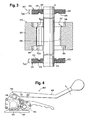
- FIG. 4 One example of a tool that may be used with the present invention is illustrated in FIG. 4 .
- a tool can, for example, be a hand-held strapping tool, such as an SCM strapping tool manufactured by ITW Signode of Glenview, Illinois.
- the bearing 100 can be used in the carrier 405 (positioned in the tool body 404) that moves up and down to punch the strap.
- the carrier 405 can be subjected to considerable forces and stresses, and it has been found that such a bearing 100 functions well in this environment.
- the bearing 100 can also be positioned in the tool 400 handle 406 to permit free rotation of the handle 406 during operation.
- strapping or tensioning tools can also benefit from the present full complement needle bearing.
- Those skilled in the art will appreciate that such tools are configured to tension a strap around a load, and can include functions to, for example, adhere the strap onto itself, and cut the feed end of the strap.
- the present bearing can also be used in a tensioning tool handle or the like.
- the ring and/or the entire race may also be integrally formed with a tool for which the bearing is being used.
- the dimensions of the ring, the first washer, the second washer, and the rollers may also vary depending on the application in which the bearing is being used.
Landscapes
- Engineering & Computer Science (AREA)
- General Engineering & Computer Science (AREA)
- Mechanical Engineering (AREA)
- Rolling Contact Bearings (AREA)
Description
- The present invention is directed to a strapping or tensioning tool comprising a bearing. More particularly, the present invention is directed to a system and method for retaining in place the rollers of a full complement needle bearing of said tool.
- Needle bearings are one of the well-known types of bearings used to provide low-friction movement between two surfaces. Needle bearings include an outer bearing ring that permits a set of rollers to roll between an inner surface of the outer bearing ring and a shaft inserted into the bearing. Generally, the rollers used in needle bearings have high length-to-diameter ratios (hence the name the needle bearing) as compared to typical roller bearings.
- One type of needle bearing is a full complement needle bearing. Full complement needle bearings typically include a full complement of rollers packed against each other around an entire periphery to define the bearing surface, but do not include any inner ring or cage to retain the rollers. This design provides the highest load-to-size ratio for a given roller diameter and length, thus minimizing the amount of space required for the bearing.
- However, there are drawbacks to the typical full complement needle bearing design. Most notably, whenever the shaft is removed to perform maintenance or to lubricate the bearing, the rollers tend to fall out of the outer bearing ring. The rollers are then difficult and tedious to replace.
- Accordingly, there is a need for an improved strapping or tensioning tool comprising a full-complement needle bearing in which the rollers are maintained in place with the shaft removed. Desirably, such a bearing is compact and provides a high load-to-size ratio. A similar bearing is known from
US 1,972,355 , while a needle bearing is disclosed comprising an outer race formed of three components, namely a ring and two washers forming radially inwardly directed collars on opposing ends of the race to form a channel wherein a plurality of rollers is disposed within the channel with a very small clearance between the rollers. Moreover, fromDE 28 24 151 A a strapping tool is disclosed. The shown tool discloses a handle and even ratchets. Full complement needle bearings with separate two washers received in respective counterbores of an outer ring are also known from the prior art, for example fromUS 2,166,673 A ,US 2,259,325 A andCH 257 817 A US 2002/129501 A1 is also a prior art document disclosing a strapping machine.
According to the invention there is provided a strapping tool or a tensioning tool comprising a bearing as defined in claim 1. - The bearing of the tool includes a race and a plurality of rollers. The race has first and second radially inwardly directed collars on opposing ends of the race to form a channel. The first collar includes a first groove formed along an inner surface of the first collar, and the second collar includes a second groove formed along an inner surface of the second collar.
- Each of the plurality of rollers has a central portion, a first nib extending from one end of the central portion and a second nib extending from an opposing end of the central portion. At least a portion of the first nib is positioned within the first groove and at least a portion of the second nib is positioned within the second groove to retain the plurality of rollers within the channel. The bearing is a full-complement needle bearing and is configured so that the rollers are maintained in place with the shaft removed. The race is formed from three components.
- In one aspect of the invention, the race may be formed from a ring, a first washer, and a second washer. The ring includes a first counterbore formed in a first side of the ring and a second counterbore formed in an opposing side of the ring. The first counterbore is shaped so as to receive at least a portion of the first washer and the second counterbore is shaped so as to receive at least a portion of the second washer. The first and second grooves are formed on inner surfaces of the first and second washers.
- These and other features and advantages of the present invention will be apparent from the following detailed description, in conjunction with the appended claims.
- The benefits and advantages of the present invention will become more readily apparent to those of ordinary skill in the relevant art after reviewing the following detailed description and accompanying drawings, wherein:
-
FIG. 1 illustrates a cross-section of one embodiment of a full complement needle bearing according to the present invention; -
FIG. 2 illustrates a cross-section of another embodiment of a bearing according to the present invention; -
FIG. 3 illustrates a cross-section plan view of a bearing race according to the present invention; -
FIG. 4 is an exemplary tool in which the present bearing can be used in the tool handle and carrier; -
FIG. 5 is an exploded view of another exemplary tool in which the bearing can be used in the tool handle and carrier; -
FIG. 6 is an illustration of a stand-alone bearing; and -
FIG. 7 is an illustration of the bearing incorporated into a tool handle. - While the present invention is susceptible of embodiment in various forms, there is shown in the figures and will hereinafter be described a presently preferred embodiment with the understanding that the present disclosure is to be considered an exemplification of the invention and is not intended to limit the invention to the specific embodiment illustrated.
- It should be further understood that the title of this section of the specification, namely, "Detailed Description Of The Invention", does not imply, nor should be inferred to limit the subject matter disclosed herein.
- Referring to the figures, and in particular to
FIG. 1 , there is shown an embodiment of a full complement needle bearing 100 embodying the principles of the present invention. The bearing includes arace 110 and a set of rollers 140. Therace 110 is a support or carriage to secure and maintain the rollers 140. Therace 110 includes two radially inwardly directedcollars radial channel 116 for the rollers 140. Each of thecollars inner groove channel 116 wall. Theinner grooves - Each of the rollers 140 has a
central portion 142 and twonibs central portion 142. Thenibs central portion 142. Thecentral portion 142 is cylindrical in shape and preferably has a length l142 that is approximately equal to, or slightly less than, a width w116 of thechannel 116 formed between thecollars bearing 100 in order to allow for low-friction rotation of the shaft relative to thebearing 100. Each of the rollers 140 is a needle roller having a length l140 that is substantially greater than its diameter d140. - The
nibs inner grooves FIG. 1 , thenibs central portion 142. The diameter (e.g., d144) of thenibs inner grooves inner grooves nibs - In an alternate embodiment shown in
FIG. 2 , thenibs central portion 242 have a diameter larger than at the distal ends. Of course, it is understood that other shapes may also be used so long as therollers 240 are capable of being retained in the channel by theinner grooves - As best illustrated in
FIG. 3 , therace 310 may be formed from three components: anouter ring 350, afirst washer 360, and asecond washer 370. Theinner surface 358 ofring 350 is generally cylindrical in shape and includes afirst counterbore 352 formed in a first side of therace 310, and asecond counterbore 354 formed in an opposing side of therace 310. Those skilled in the art will recognize that housings of other shapes (e.g., incorporation into tool handles) can be used, which housings are intended to rotate freely. - The first and
second washers second counterbores exterior edge 362 that defines a diameter approximately equal to a diameter of aperipheral edge 356 of thefirst counterbore 352, and aninterior edge 364 having a diameter greater than a diameter of the shaft S. Thefirst washer 360 also preferably has a thickness t360 that is approximately equal to a depth d352 of thefirst counterbore 352. Similarly, thesecond washer 370 has anexterior edge 372 having a diameter approximately equal to a diameter of aperipheral edge 359 of thesecond counterbore 354, and aninterior edge 374 that defines a diameter greater than a diameter of the shaft S. Thewasher 370 has a thickness t370 that is approximately equal to a depth d354 of thesecond counterbore 354. Theinner grooves washer inner surface 358 of thering 350 when thewashers ring 350. Thus, when positioned within the first andsecond counterbores collars 312 and 314. This configuration is proved so that a shaft S positioned in thebearing 300 rides on the rollers (not shown), and is free to rotate and is free from contact with the washerinner surfaces - To assemble the
bearing 300, thefirst washer 360 is secured by pressing thefirst washer 360 into thefirst counterbore 352. One nib of each of the rollers is placed into theinner groove 320 of thefirst washer 360. Thesecond washer 370 is then secured into thesecond counterbore 354 such that the opposing nib of each roller is within theinner groove 318 of thesecond washer 370. The rollers, by virtue of theinner grooves race channel 316. As a result, the rollers are prevented from falling out of therace 310 when a shaft S is removed from the center of thebearing 300. - One example of a tool that may be used with the present invention is illustrated in
FIG. 4 . Such a tool can, for example, be a hand-held strapping tool, such as an SCM strapping tool manufactured by ITW Signode of Glenview, Illinois. In atool 400 of, for example, this type of tool, the bearing 100 can be used in the carrier 405 (positioned in the tool body 404) that moves up and down to punch the strap. Thecarrier 405 can be subjected to considerable forces and stresses, and it has been found that such abearing 100 functions well in this environment. The bearing 100 can also be positioned in thetool 400handle 406 to permit free rotation of thehandle 406 during operation. - Other strapping or tensioning tools, including manual and powered tools can also benefit from the present full complement needle bearing. Those skilled in the art will appreciate that such tools are configured to tension a strap around a load, and can include functions to, for example, adhere the strap onto itself, and cut the feed end of the strap. The present bearing can also be used in a tensioning tool handle or the like.
- Use of a full complement bearing allows the size of the strapping tool to be compact while providing a bearing that is capable of retaining the rollers when maintenance is performed on the component of the tool that is carried by the bearing (e.g., the shaft carried by the bearing).
- It is also understood that various aspects and design features of the bearing may be modified without departing from the scope of the invention. The ring and/or the entire race may also be integrally formed with a tool for which the bearing is being used. The dimensions of the ring, the first washer, the second washer, and the rollers may also vary depending on the application in which the bearing is being used.
- In the present disclosure, the words "a" or "an" are to be taken to include both the singular and the plural. Conversely, any reference to plural items shall, where appropriate, include the singular.
- From the foregoing it will be observed that numerous modifications and variations can be effectuated without departing from the scope of the present invention. It is to be understood that no limitation with respect to the specific embodiments illustrated is intended or should be inferred. The disclosure is intended to cover all such modifications as fall within the scope of the claims.
Claims (8)
- A strapping tool or a tensioning tool (400) comprising a full complement needle bearing (100, 300),
the full complement needle bearing (100, 300) is comprising:a race (110, 310) having first and second radially inwardly directed collars (112, 114) on opposing ends of the race to form a channel (116, 316); the first collar (112) having a first groove (120) formed along an inner surface of the first collar, and the second collar (114) having a second groove (118) formed along an inner surface of the second collar; anda plurality of rollers (140, 240) disposed within the channel (116, 316); each of said plurality of rollers having a central portion (142, 242); a first nib (146, 246) extending from one end of the central portion and a second nib (144, 244) extending from an opposing end of the central portion,wherein at least a portion of the first nib (146, 246) is retained within the first groove (120) and at least a portion of the second nib (144, 244) is retained within the second groove (118),the race (110, 310) being formed from three components, namely a ring (350) or housing of other shape intended to rotate freely, a first washer (360) and a second washer (370). - The tool of claim 1 wherein each of the first and second nibs (144, 146) is substantially cylindrical in shape.
- The tool of claim 1 wherein each of the first and second nibs (244, 246) is tapered.
- The tool of claim 1 wherein the race is comprised of a ring, a first washer, and a second washer and the ring (350) is substantially cylindrical in shape.
- The tool of claim 4 wherein the ring (350) includes a first counterbore (352) formed in a first side of the ring and a second counterbore (354) formed in an opposing side of the ring, and wherein the first counterbore (352) is shaped so as to receive at least a portion of the first washer (360) and the second counterbore (354) is shaped so as to receive at least a portion of the second washer (370).
- The tool of claim 5 wherein the first groove (120) is formed in an inner surface of the first washer (360) and the second groove (118) is formed in an inner surface of the second washer (370).
- The tool of claim 1 whereby the bearing (100, 300) is disposed in a handle (406) of the tool (400).
- The tool of claim 1 wherein the bearing (100, 300) is disposed in the carrier of a tool.
Applications Claiming Priority (1)
| Application Number | Priority Date | Filing Date | Title |
|---|---|---|---|
| US11/621,659 US20080166081A1 (en) | 2007-01-10 | 2007-01-10 | System and method for retaining rollers of a full complement needle bearing |
Publications (3)
| Publication Number | Publication Date |
|---|---|
| EP1944517A2 EP1944517A2 (en) | 2008-07-16 |
| EP1944517A3 EP1944517A3 (en) | 2008-07-23 |
| EP1944517B1 true EP1944517B1 (en) | 2015-01-21 |
Family
ID=39415287
Family Applications (1)
| Application Number | Title | Priority Date | Filing Date |
|---|---|---|---|
| EP07020985.3A Not-in-force EP1944517B1 (en) | 2007-01-10 | 2007-10-26 | Full complement needle bearing with retaining grooves for the needles in the collars of the outer race |
Country Status (3)
| Country | Link |
|---|---|
| US (1) | US20080166081A1 (en) |
| EP (1) | EP1944517B1 (en) |
| CA (1) | CA2608877C (en) |
Families Citing this family (2)
| Publication number | Priority date | Publication date | Assignee | Title |
|---|---|---|---|---|
| KR20170021340A (en) | 2014-07-30 | 2017-02-27 | 코요 베어링즈 노쓰 아메리카 엘엘씨 | Roller bearing assembly with retainer ring |
| US10448583B2 (en) * | 2015-10-05 | 2019-10-22 | Deere & Company | Disc saw felling head for a feller buncher |
Citations (1)
| Publication number | Priority date | Publication date | Assignee | Title |
|---|---|---|---|---|
| US1972355A (en) * | 1933-02-21 | 1934-09-04 | Frederick W Peters | Roller bearing |
Family Cites Families (9)
| Publication number | Priority date | Publication date | Assignee | Title |
|---|---|---|---|---|
| US2016923A (en) * | 1934-05-19 | 1935-10-08 | Karl L Herrmann | Antifriction bearing and method of making same |
| US2038475A (en) * | 1934-09-10 | 1936-04-21 | Torrington Co | Antifriction bearing and method of making the same |
| US2166673A (en) * | 1938-05-21 | 1939-07-18 | Roller Bearing Co Of America | Roller retainer ring and race member assembly for roller bearings |
| US2259325A (en) * | 1939-12-23 | 1941-10-14 | Thomas L Robinson | Roller bearing |
| GB558342A (en) * | 1942-10-16 | 1943-12-31 | Hardy Spicer & Co Ltd | Improvements in needle bearings |
| CH257817A (en) * | 1947-06-03 | 1948-10-31 | Ag Kugellagerfabrik Arbon | Needle roller bearings with needle retention. |
| CH627139A5 (en) * | 1978-02-14 | 1981-12-31 | Fromm Ag | Apparatus for connecting two mutually overlapping band parts |
| US6554030B2 (en) * | 2001-03-19 | 2003-04-29 | Illinois Tool Works Inc. | Progressive punch |
| NZ519012A (en) * | 2001-05-21 | 2003-10-31 | Orgapack Gmbh | Manually actuated strapping unit for wrapping a steel strap around a packaged item |
-
2007
- 2007-01-10 US US11/621,659 patent/US20080166081A1/en not_active Abandoned
- 2007-10-26 EP EP07020985.3A patent/EP1944517B1/en not_active Not-in-force
- 2007-10-29 CA CA2608877A patent/CA2608877C/en not_active Expired - Fee Related
Patent Citations (1)
| Publication number | Priority date | Publication date | Assignee | Title |
|---|---|---|---|---|
| US1972355A (en) * | 1933-02-21 | 1934-09-04 | Frederick W Peters | Roller bearing |
Also Published As
| Publication number | Publication date |
|---|---|
| US20080166081A1 (en) | 2008-07-10 |
| EP1944517A2 (en) | 2008-07-16 |
| CA2608877C (en) | 2014-06-03 |
| EP1944517A3 (en) | 2008-07-23 |
| CA2608877A1 (en) | 2008-07-10 |
Similar Documents
| Publication | Publication Date | Title |
|---|---|---|
| EP2068020B1 (en) | Rolling bearing apparatus | |
| EP2787231B1 (en) | Prong type cage for double row roller bearing and double row roller bearing | |
| WO2009154106A1 (en) | Cylindrical roller bearing | |
| EP1870608B1 (en) | Rolling bearing and cage for rolling bearing | |
| JP2009068592A (en) | Spherical roller bearing with cage and manufacturing method of cage for spherical roller bearing | |
| EP3527839A1 (en) | Retainer for angular ball bearings | |
| CA2608877C (en) | System and method for retaining rollers of a full complement needle bearing | |
| WO2008078786A1 (en) | Thrust roller bearing | |
| EP1760345B1 (en) | Tapered roller bearing assembling device | |
| JP5286959B2 (en) | Cylindrical roller bearing | |
| JP2012117582A (en) | Needle bearing | |
| JP2012021579A (en) | Roller bearing device | |
| JP5315905B2 (en) | Cylindrical roller bearing | |
| JP2010091007A (en) | Retainer for conical roller bearing, and conical roller bearing | |
| JP6557950B2 (en) | Solid needle bearing | |
| JP5499451B2 (en) | Roller bearing of planetary gear mechanism | |
| JP2010159787A (en) | Thrust roller bearing | |
| JP4561501B2 (en) | Method for manufacturing roller bearing cage | |
| JP2011099480A (en) | Cage for roller bearing and roller bearing | |
| KR102284911B1 (en) | Custom anvil roller module | |
| JP2568806Y2 (en) | Lubricating device for cylindrical roller bearings | |
| JP2005098453A (en) | Rolling bearing | |
| EP2860414B1 (en) | Conical roller bearing | |
| JP2010164081A (en) | Cage and roller, and radial needle bearing | |
| JP5169719B2 (en) | Roller bearing of planetary gear mechanism |
Legal Events
| Date | Code | Title | Description |
|---|---|---|---|
| PUAI | Public reference made under article 153(3) epc to a published international application that has entered the european phase |
Free format text: ORIGINAL CODE: 0009012 |
|
| PUAL | Search report despatched |
Free format text: ORIGINAL CODE: 0009013 |
|
| AK | Designated contracting states |
Kind code of ref document: A2 Designated state(s): AT BE BG CH CY CZ DE DK EE ES FI FR GB GR HU IE IS IT LI LT LU LV MC MT NL PL PT RO SE SI SK TR |
|
| AX | Request for extension of the european patent |
Extension state: AL BA HR MK RS |
|
| AK | Designated contracting states |
Kind code of ref document: A3 Designated state(s): AT BE BG CH CY CZ DE DK EE ES FI FR GB GR HU IE IS IT LI LT LU LV MC MT NL PL PT RO SE SI SK TR |
|
| AX | Request for extension of the european patent |
Extension state: AL BA HR MK RS |
|
| 17P | Request for examination filed |
Effective date: 20080829 |
|
| 17Q | First examination report despatched |
Effective date: 20081001 |
|
| AKX | Designation fees paid |
Designated state(s): CH DE ES FR IT LI |
|
| RAP1 | Party data changed (applicant data changed or rights of an application transferred) |
Owner name: ILLINOIS TOOL WORKS INC. |
|
| RAP1 | Party data changed (applicant data changed or rights of an application transferred) |
Owner name: PREMARK PACKAGING LLC |
|
| RAP1 | Party data changed (applicant data changed or rights of an application transferred) |
Owner name: SIGNODE INTERNATIONAL IP HOLDINGS LLC |
|
| GRAP | Despatch of communication of intention to grant a patent |
Free format text: ORIGINAL CODE: EPIDOSNIGR1 |
|
| INTG | Intention to grant announced |
Effective date: 20141029 |
|
| RIN1 | Information on inventor provided before grant (corrected) |
Inventor name: CRITTENDEN, DAVID E. Inventor name: FIGIEL, JANUSZ |
|
| GRAS | Grant fee paid |
Free format text: ORIGINAL CODE: EPIDOSNIGR3 |
|
| GRAA | (expected) grant |
Free format text: ORIGINAL CODE: 0009210 |
|
| AK | Designated contracting states |
Kind code of ref document: B1 Designated state(s): CH DE ES FR IT LI |
|
| REG | Reference to a national code |
Ref country code: CH Ref legal event code: EP |
|
| REG | Reference to a national code |
Ref country code: DE Ref legal event code: R096 Ref document number: 602007040096 Country of ref document: DE Effective date: 20150305 |
|
| PG25 | Lapsed in a contracting state [announced via postgrant information from national office to epo] |
Ref country code: ES Free format text: LAPSE BECAUSE OF FAILURE TO SUBMIT A TRANSLATION OF THE DESCRIPTION OR TO PAY THE FEE WITHIN THE PRESCRIBED TIME-LIMIT Effective date: 20150121 |
|
| REG | Reference to a national code |
Ref country code: DE Ref legal event code: R097 Ref document number: 602007040096 Country of ref document: DE |
|
| PLBE | No opposition filed within time limit |
Free format text: ORIGINAL CODE: 0009261 |
|
| STAA | Information on the status of an ep patent application or granted ep patent |
Free format text: STATUS: NO OPPOSITION FILED WITHIN TIME LIMIT |
|
| 26N | No opposition filed |
Effective date: 20151022 |
|
| PG25 | Lapsed in a contracting state [announced via postgrant information from national office to epo] |
Ref country code: IT Free format text: LAPSE BECAUSE OF FAILURE TO SUBMIT A TRANSLATION OF THE DESCRIPTION OR TO PAY THE FEE WITHIN THE PRESCRIBED TIME-LIMIT Effective date: 20150121 |
|
| REG | Reference to a national code |
Ref country code: DE Ref legal event code: R119 Ref document number: 602007040096 Country of ref document: DE |
|
| REG | Reference to a national code |
Ref country code: CH Ref legal event code: PL |
|
| PG25 | Lapsed in a contracting state [announced via postgrant information from national office to epo] |
Ref country code: DE Free format text: LAPSE BECAUSE OF NON-PAYMENT OF DUE FEES Effective date: 20160503 Ref country code: CH Free format text: LAPSE BECAUSE OF NON-PAYMENT OF DUE FEES Effective date: 20151031 Ref country code: LI Free format text: LAPSE BECAUSE OF NON-PAYMENT OF DUE FEES Effective date: 20151031 |
|
| REG | Reference to a national code |
Ref country code: FR Ref legal event code: ST Effective date: 20160630 |
|
| PG25 | Lapsed in a contracting state [announced via postgrant information from national office to epo] |
Ref country code: FR Free format text: LAPSE BECAUSE OF NON-PAYMENT OF DUE FEES Effective date: 20151102 |