EP1944439A2 - Collapsible lock for a vehicle hood - Google Patents
Collapsible lock for a vehicle hood Download PDFInfo
- Publication number
- EP1944439A2 EP1944439A2 EP20070380353 EP07380353A EP1944439A2 EP 1944439 A2 EP1944439 A2 EP 1944439A2 EP 20070380353 EP20070380353 EP 20070380353 EP 07380353 A EP07380353 A EP 07380353A EP 1944439 A2 EP1944439 A2 EP 1944439A2
- Authority
- EP
- European Patent Office
- Prior art keywords
- case
- frame
- lock
- front framework
- framework
- Prior art date
- Legal status (The legal status is an assumption and is not a legal conclusion. Google has not performed a legal analysis and makes no representation as to the accuracy of the status listed.)
- Withdrawn
Links
- 230000006835 compression Effects 0.000 claims description 7
- 238000007906 compression Methods 0.000 claims description 7
- 208000027418 Wounds and injury Diseases 0.000 description 2
- 238000010521 absorption reaction Methods 0.000 description 2
- 230000006378 damage Effects 0.000 description 2
- 208000014674 injury Diseases 0.000 description 2
- 230000000694 effects Effects 0.000 description 1
Images

Classifications
-
- E—FIXED CONSTRUCTIONS
- E05—LOCKS; KEYS; WINDOW OR DOOR FITTINGS; SAFES
- E05B—LOCKS; ACCESSORIES THEREFOR; HANDCUFFS
- E05B77/00—Vehicle locks characterised by special functions or purposes
- E05B77/02—Vehicle locks characterised by special functions or purposes for accident situations
- E05B77/08—Arrangements for protection of pedestrians
Definitions
- the present invention relates to a collapsible lock for a vehicle hood, comprising a case or frame which is fixed to the front framework of the vehicle, generally at the upper part thereof and which can be actuated from inside the vehicle.
- the front framework is provided with a lock which is usually actuated from inside the vehicle.
- This lock is internally assembled at the upper part of the front framework and is usually fixed thereto by means of screws, such that its immobility is assured.
- This arrangement makes the lock form a point of the front framework of maximum hardness, which can entail a considerable risk in the event of running over and colliding with a pedestrian.
- the object of the present invention is to eliminate the problem set forth by means of a lock which is assembled in the hood by means of a retractable mechanism, with certain deformation capacity, the purpose of which is to absorb the energy produced as a result of an impact against the vehicle hood, for example due to running over a pedestrian.
- the case or frame of the lock is assembled in the front framework with the capacity of relative vertical movement with respect to said framework, and is connected thereto through fixing means allowing a certain movement between the front framework and the case or frame when a force exceeding a prefixed value is applied on the hood.
- the lock is further connected to the front framework through elastic supports absorbing the energy of the impact, as they are deformed during the relative vertical movement of the case of frame of the lock.
- the fixing means for fixing the lock to the front framework can consist of screws traversing the hood through vertical mounting holes, though which the screws and thus the frame or case of the lock can move vertically when an impact occurs on the hood with a force exceeding a prefixed value.
- the aforementioned elastic supports are assembled between the case or frame of the lock and the front framework and consist of two vertical compression springs, assembled in a compressed condition under the lock, between said lock and the framework, and of two horizontal compression springs supported at one side on the hood structure and at the opposite side on a rotating eccentric cam which is articulated, at a point opposite to the support point with the spring, to a vertical arm on which the lock is supported.
- a gas spring is housed inside each horizontal spring to absorb the energy due to an impact.
- the horizontal springs, plus the gas springs, can be housed in a case assembled in the front framework, the case of which is transversely open at the support side of the cam.
- Figure 1 shows an inner elevational view of a vehicle front framework 1, including an outer cover 2 and an inner structure 3.
- the case or frame 4 of a lock is assembled between the cover and structure, which case or frame can generally be actuated from inside the vehicle.
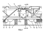
- the case or frame 4 of the lock is fixed to the front framework 1 by means of screws 5, Figure 2 , passing through mounting holes 6 made in the structure 3 of the front framework 1, these mounting holes running in a vertical direction.
- the screws 5 will be tightened with a strain such that the when the hood and the lock 4 receive an impact the intensity of which exceeds a prefixed value, the screws 5 can move downwards along the mounting holes 6, thus allowing the hood to move in the same direction with respect to the front framework 1, which is the fixed part of the vehicle structure.
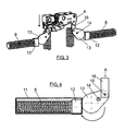
- the lock 4 is connected to the structure 3 of the front framework 1 by means of elastic supports including 2 vertical compression springs 7, assembled under the case 4 of the lock, between the latter and the structure 3 of the front framework, and two horizontal compression springs 8, all of this as can best be seen in Figure 3 .
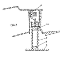
- the vertical springs 7 are fixed between cylindrical inserts 9 and 10, Figure 7 , fixed to an element of the structure 3 of the front framework 1 and to the case or frame 4 of the lock, respectively.
- each horizontal spring 8 is housed in a case 11 which is fixed to the structure 3 of the front framework 1, which is transversely open at one side.
- a gas spring is housed inside each spring 8, the head 12 of which gas spring is supported, through the open transverse wall of the case, on an eccentric cam 13 rotating about an axis 14, which cam is articulated at a point opposite to the support point with the head 12, with a vertical arm or flat bar on which the case 4 or rack of the lock rests or is supported, Figure 4 .
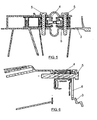
- Figures 5 and 6 show how the fixing screws 5 pass through the mounting holes 6 of the structure 3 of the front framework 1, said screws being able to move together with the case 4 of the lock in a vertical direction, when the hood receives an impact, as a result of running over a pedestrian, for example.
- the lock 4 will act directly on the springs 7 in its vertical movement, whereas in the springs 8, upon pushing the lock in direction A of Figure 4 , a rotation of the eccentric cam 13 about the axis 14 will occur, which will press on the head 12 of the spring 8, compressing it, which will cause the gas spring housed in said spring 8 to act as an energy absorption means, in the event of an impact.
- the gas springs inside the horizontal springs 8 thus act as energy absorption means, to reduce the effect of the impact caused as a result of running over, as the intrusion of the hood in the front framework is allowed, thus reducing the risks of injuries to the pedestrian or person who is run over.
Landscapes
- Superstructure Of Vehicle (AREA)
Abstract
The invention relates to a collapsible lock for a vehicle hood, comprising a case or frame (4) which is assembled in the front framework (11) of the vehicle with the capacity of vertical movement and is connected thereto through fixing means and through elastic supports (7-8) allowing the movement between the hood and the front framework when a force exceeding a prefixed value is applied on the hood.
Description
- The present invention relates to a collapsible lock for a vehicle hood, comprising a case or frame which is fixed to the front framework of the vehicle, generally at the upper part thereof and which can be actuated from inside the vehicle.
- To assure the closing position of a vehicle hood, the front framework is provided with a lock which is usually actuated from inside the vehicle. This lock is internally assembled at the upper part of the front framework and is usually fixed thereto by means of screws, such that its immobility is assured.
- This arrangement makes the lock form a point of the front framework of maximum hardness, which can entail a considerable risk in the event of running over and colliding with a pedestrian.
- The object of the present invention is to eliminate the problem set forth by means of a lock which is assembled in the hood by means of a retractable mechanism, with certain deformation capacity, the purpose of which is to absorb the energy produced as a result of an impact against the vehicle hood, for example due to running over a pedestrian.
- With this arrangement the point of high hardness of the hood is eliminated, due to the assembly of the lock, and thus the risk of injuries in the event of running over a pedestrian is reduced.
- According to the invention, the case or frame of the lock is assembled in the front framework with the capacity of relative vertical movement with respect to said framework, and is connected thereto through fixing means allowing a certain movement between the front framework and the case or frame when a force exceeding a prefixed value is applied on the hood. The lock is further connected to the front framework through elastic supports absorbing the energy of the impact, as they are deformed during the relative vertical movement of the case of frame of the lock.
- The fixing means for fixing the lock to the front framework can consist of screws traversing the hood through vertical mounting holes, though which the screws and thus the frame or case of the lock can move vertically when an impact occurs on the hood with a force exceeding a prefixed value.
- The aforementioned elastic supports are assembled between the case or frame of the lock and the front framework and consist of two vertical compression springs, assembled in a compressed condition under the lock, between said lock and the framework, and of two horizontal compression springs supported at one side on the hood structure and at the opposite side on a rotating eccentric cam which is articulated, at a point opposite to the support point with the spring, to a vertical arm on which the lock is supported. A gas spring is housed inside each horizontal spring to absorb the energy due to an impact. The horizontal springs, plus the gas springs, can be housed in a case assembled in the front framework, the case of which is transversely open at the support side of the cam.
- The attached drawings show a non-limiting embodiment, with the aid of which the constitution and operation of the lock of the invention can be better understood.
- In the drawings:
-
Figure 1 shows an inner elevational view of a vehicle front framework, with the lock thereof assembled according to the invention. -
Figure 2 shows a view similar toFigure 1 , showing the mounting holes made in the front framework, to fix the lock. -
Figure 3 shows a perspective view of the lock with the elastic means connecting it to the front framework. -
Figure 4 shows a side elevational view of one of the horizontal compression springs. -
Figure 5 shows a schematic section of the lock assembled in the front framework, according to section line V-V ofFigure 2 . -
Figures 6 and7 show vertical sections of the lock, taken along section lines VI-VI and VII-VII ofFigure 2 . -
Figure 1 shows an inner elevational view of avehicle front framework 1, including anouter cover 2 and aninner structure 3. The case orframe 4 of a lock is assembled between the cover and structure, which case or frame can generally be actuated from inside the vehicle. - The case or
frame 4 of the lock is fixed to thefront framework 1 by means ofscrews 5,Figure 2 , passing throughmounting holes 6 made in thestructure 3 of thefront framework 1, these mounting holes running in a vertical direction. - To fix the
case 4 of the lock to thefront framework 1, thescrews 5 will be tightened with a strain such that the when the hood and thelock 4 receive an impact the intensity of which exceeds a prefixed value, thescrews 5 can move downwards along themounting holes 6, thus allowing the hood to move in the same direction with respect to thefront framework 1, which is the fixed part of the vehicle structure. - In addition, the
lock 4 is connected to thestructure 3 of thefront framework 1 by means of elastic supports including 2vertical compression springs 7, assembled under thecase 4 of the lock, between the latter and thestructure 3 of the front framework, and twohorizontal compression springs 8, all of this as can best be seen inFigure 3 . - The
vertical springs 7 are fixed betweencylindrical inserts Figure 7 , fixed to an element of thestructure 3 of thefront framework 1 and to the case orframe 4 of the lock, respectively. - As can best be seen in
Figure 4 , eachhorizontal spring 8 is housed in acase 11 which is fixed to thestructure 3 of thefront framework 1, which is transversely open at one side. A gas spring is housed inside eachspring 8, thehead 12 of which gas spring is supported, through the open transverse wall of the case, on aneccentric cam 13 rotating about anaxis 14, which cam is articulated at a point opposite to the support point with thehead 12, with a vertical arm or flat bar on which thecase 4 or rack of the lock rests or is supported,Figure 4 . -
Figures 5 and 6 show how thefixing screws 5 pass through themounting holes 6 of thestructure 3 of thefront framework 1, said screws being able to move together with thecase 4 of the lock in a vertical direction, when the hood receives an impact, as a result of running over a pedestrian, for example. - The movement of the
screws 5 andcase 4 of the lock is controlled bysprings - The
lock 4 will act directly on thesprings 7 in its vertical movement, whereas in thesprings 8, upon pushing the lock in direction A ofFigure 4 , a rotation of theeccentric cam 13 about theaxis 14 will occur, which will press on thehead 12 of thespring 8, compressing it, which will cause the gas spring housed in saidspring 8 to act as an energy absorption means, in the event of an impact. - The gas springs inside the
horizontal springs 8 thus act as energy absorption means, to reduce the effect of the impact caused as a result of running over, as the intrusion of the hood in the front framework is allowed, thus reducing the risks of injuries to the pedestrian or person who is run over.
Claims (5)
- A collapsible lock for a vehicle hood, comprising a case or frame (4) which is fixed to the structure (3) of the vehicle front framework (1), characterized in that the mentioned case or frame is assembled in the front framework with the capacity of relative vertical movement and is connected to said framework through fixing means and through elastic supports allowing the movement between the hood and the front framework when a force exceeding a prefixed value is applied on the hood.
- A lock according to claim 1, characterized in that the fixing means connecting the case or frame (4) to the front framework (1) consist of screws (5) traversing said framework through vertical mounting holes (6), along which the screws and the case or frame can move vertically.
- A lock according to claim 1, characterized in that the mentioned elastic supports consist of 2 vertical compression springs (7) located under the case or frame (4), which are assembled in a compressed condition between said case or frame and the front framework (1), and of two horizontal compression springs (8) which are supported at one side on the structure (3) of the front framework (1) and at the opposite side on a rotating eccentric cam (1) which is articulated at a point (15) opposite to the support point with the spring, to a vertical arm (16) on which the case or frame of the lock is supported.
- A lock according to claim 3, characterized in that each of the mentioned horizontal springs (8) is housed in a case (11) assembled in the front framework, the case of which is transversely open at the support side of the cam (13).
- A lock according to claims 3 and 4, characterized in that a gas spring is housed inside each horizontal spring, to absorb energy in the event of an impact, through the head (12) of which gas spring said horizontal spring is supported in the rotating eccentric cam (13).
Applications Claiming Priority (1)
| Application Number | Priority Date | Filing Date | Title |
|---|---|---|---|
| ES200602769U ES1064564Y (en) | 2006-12-26 | 2006-12-26 | COLLAPSABLE LOCK FOR CAR COAT |
Publications (1)
| Publication Number | Publication Date |
|---|---|
| EP1944439A2 true EP1944439A2 (en) | 2008-07-16 |
Family
ID=38319357
Family Applications (1)
| Application Number | Title | Priority Date | Filing Date |
|---|---|---|---|
| EP20070380353 Withdrawn EP1944439A2 (en) | 2006-12-26 | 2007-12-13 | Collapsible lock for a vehicle hood |
Country Status (2)
| Country | Link |
|---|---|
| EP (1) | EP1944439A2 (en) |
| ES (1) | ES1064564Y (en) |
-
2006
- 2006-12-26 ES ES200602769U patent/ES1064564Y/en not_active Expired - Fee Related
-
2007
- 2007-12-13 EP EP20070380353 patent/EP1944439A2/en not_active Withdrawn
Also Published As
| Publication number | Publication date |
|---|---|
| ES1064564U (en) | 2007-04-01 |
| ES1064564Y (en) | 2007-07-01 |
Similar Documents
| Publication | Publication Date | Title |
|---|---|---|
| KR100770135B1 (en) | Pedestrian Protective Device for Car Hood | |
| AU2006289596B2 (en) | Pedestrian protection automotive hood hinge assembly | |
| JPH0396428A (en) | Automobile door | |
| CN110341564B (en) | An external energy-absorbing seat | |
| US20110126469A1 (en) | Hinge and door unit | |
| JPH11263181A (en) | Automobile bumper mechanism of protection against impact | |
| CN106609613A (en) | Passive hood hinge system for vehicle | |
| DE10014832A1 (en) | Safety system for motor vehicle has one or more inflatable airbags for damping support of raised hood and/or large volume coverage of at least most of windscreen frame with hood raised | |
| DE10102760A1 (en) | Safety system with impact-absorbent engine bonnet for motor vehicles has energy absorber in rear area of front body section and is connected to a collision detection device | |
| JP2007501161A (en) | A device that manually reverses a device that protects people in the event of a frontal collision with an automobile | |
| EP1554164A1 (en) | Device for protecting persons during a head-on collision of a motor vehicle | |
| DE10252560A1 (en) | Arrangement for motor vehicle for protecting persons against impact, has hood lifting spring free to bend transversely to lifting direction when released by lateral forces via front hood | |
| CN1520362A (en) | Motor vehicle body with an elastically supported front panel | |
| DE10326404B4 (en) | Device for protecting people in a frontal collision with a motor vehicle | |
| CN206826579U (en) | A kind of buffer type motor vehicle bumper | |
| CN103692938A (en) | Safety seat and energy absorbers thereof | |
| KR100673314B1 (en) | Shock Absorber | |
| RU2554909C2 (en) | Barrier device | |
| CN216231626U (en) | A door frame assembly for an electric vehicle | |
| CN111572420A (en) | Military vehicle lightning protection seat energy-absorbing device | |
| JP2006520296A (en) | Device to protect people in frontal collision with motor vehicle | |
| KR20090005582A (en) | Hood Striker Improved Structure for Automotive | |
| CN209566878U (en) | A kind of bump-proof rod for automobile door | |
| CN210478457U (en) | Integrated energy-absorbing seat | |
| CN215097445U (en) | Rail guard device under truck |
Legal Events
| Date | Code | Title | Description |
|---|---|---|---|
| PUAI | Public reference made under article 153(3) epc to a published international application that has entered the european phase |
Free format text: ORIGINAL CODE: 0009012 |
|
| AK | Designated contracting states |
Kind code of ref document: A2 Designated state(s): AT BE BG CH CY CZ DE DK EE ES FI FR GB GR HU IE IS IT LI LT LU LV MC MT NL PL PT RO SE SI SK TR |
|
| AX | Request for extension of the european patent |
Extension state: AL BA HR MK RS |
|
| STAA | Information on the status of an ep patent application or granted ep patent |
Free format text: STATUS: THE APPLICATION IS DEEMED TO BE WITHDRAWN |
|
| 18D | Application deemed to be withdrawn |
Effective date: 20110701 |