EP1943115B1 - Höhenkontrollventil für ein fahrzeugachsen-/aufhängungssystem - Google Patents
Höhenkontrollventil für ein fahrzeugachsen-/aufhängungssystem Download PDFInfo
- Publication number
- EP1943115B1 EP1943115B1 EP20060851317 EP06851317A EP1943115B1 EP 1943115 B1 EP1943115 B1 EP 1943115B1 EP 20060851317 EP20060851317 EP 20060851317 EP 06851317 A EP06851317 A EP 06851317A EP 1943115 B1 EP1943115 B1 EP 1943115B1
- Authority
- EP
- European Patent Office
- Prior art keywords
- air
- control valve
- height control
- air spring
- throttle assembly
- Prior art date
- Legal status (The legal status is an assumption and is not a legal conclusion. Google has not performed a legal analysis and makes no representation as to the accuracy of the status listed.)
- Active
Links
- 239000000725 suspension Substances 0.000 title claims abstract description 79
- 239000012530 fluid Substances 0.000 claims description 15
- 230000007423 decrease Effects 0.000 claims description 10
- 230000003247 decreasing effect Effects 0.000 claims description 4
- 230000000712 assembly Effects 0.000 description 14
- 238000000429 assembly Methods 0.000 description 14
- 238000007142 ring opening reaction Methods 0.000 description 14
- 230000001105 regulatory effect Effects 0.000 description 10
- 230000008901 benefit Effects 0.000 description 3
- 230000006835 compression Effects 0.000 description 3
- 238000007906 compression Methods 0.000 description 3
- 230000007935 neutral effect Effects 0.000 description 3
- 230000003213 activating effect Effects 0.000 description 2
- 230000004913 activation Effects 0.000 description 2
- 230000033228 biological regulation Effects 0.000 description 2
- 230000009977 dual effect Effects 0.000 description 2
- 238000009434 installation Methods 0.000 description 2
- 239000006096 absorbing agent Substances 0.000 description 1
- 230000003466 anti-cipated effect Effects 0.000 description 1
- 239000011324 bead Substances 0.000 description 1
- 238000006073 displacement reaction Methods 0.000 description 1
- 230000035939 shock Effects 0.000 description 1
Images


Classifications
-
- B—PERFORMING OPERATIONS; TRANSPORTING
- B60—VEHICLES IN GENERAL
- B60G—VEHICLE SUSPENSION ARRANGEMENTS
- B60G17/00—Resilient suspensions having means for adjusting the spring or vibration-damper characteristics, for regulating the distance between a supporting surface and a sprung part of vehicle or for locking suspension during use to meet varying vehicular or surface conditions, e.g. due to speed or load
- B60G17/02—Spring characteristics, e.g. mechanical springs and mechanical adjusting means
- B60G17/04—Spring characteristics, e.g. mechanical springs and mechanical adjusting means fluid spring characteristics
- B60G17/052—Pneumatic spring characteristics
- B60G17/0523—Regulating distributors or valves for pneumatic springs
- B60G17/0525—Height adjusting or levelling valves
-
- B—PERFORMING OPERATIONS; TRANSPORTING
- B60—VEHICLES IN GENERAL
- B60G—VEHICLE SUSPENSION ARRANGEMENTS
- B60G11/00—Resilient suspensions characterised by arrangement, location or kind of springs
- B60G11/26—Resilient suspensions characterised by arrangement, location or kind of springs having fluid springs only, e.g. hydropneumatic springs
- B60G11/27—Resilient suspensions characterised by arrangement, location or kind of springs having fluid springs only, e.g. hydropneumatic springs wherein the fluid is a gas
-
- B—PERFORMING OPERATIONS; TRANSPORTING
- B60—VEHICLES IN GENERAL
- B60G—VEHICLE SUSPENSION ARRANGEMENTS
- B60G9/00—Resilient suspensions of a rigid axle or axle housing for two or more wheels
- B60G9/003—Resilient suspensions of a rigid axle or axle housing for two or more wheels the axle being rigidly connected to a trailing guiding device
-
- B—PERFORMING OPERATIONS; TRANSPORTING
- B60—VEHICLES IN GENERAL
- B60G—VEHICLE SUSPENSION ARRANGEMENTS
- B60G2200/00—Indexing codes relating to suspension types
- B60G2200/30—Rigid axle suspensions
- B60G2200/31—Rigid axle suspensions with two trailing arms rigidly connected to the axle
-
- B—PERFORMING OPERATIONS; TRANSPORTING
- B60—VEHICLES IN GENERAL
- B60G—VEHICLE SUSPENSION ARRANGEMENTS
- B60G2202/00—Indexing codes relating to the type of spring, damper or actuator
- B60G2202/10—Type of spring
- B60G2202/15—Fluid spring
- B60G2202/152—Pneumatic spring
-
- B—PERFORMING OPERATIONS; TRANSPORTING
- B60—VEHICLES IN GENERAL
- B60G—VEHICLE SUSPENSION ARRANGEMENTS
- B60G2204/00—Indexing codes related to suspensions per se or to auxiliary parts
- B60G2204/10—Mounting of suspension elements
- B60G2204/11—Mounting of sensors thereon
- B60G2204/116—Sensors coupled to the suspension arm
-
- B—PERFORMING OPERATIONS; TRANSPORTING
- B60—VEHICLES IN GENERAL
- B60G—VEHICLE SUSPENSION ARRANGEMENTS
- B60G2204/00—Indexing codes related to suspensions per se or to auxiliary parts
- B60G2204/10—Mounting of suspension elements
- B60G2204/20—Mounting of accessories, e.g. pump, compressor
-
- B—PERFORMING OPERATIONS; TRANSPORTING
- B60—VEHICLES IN GENERAL
- B60G—VEHICLE SUSPENSION ARRANGEMENTS
- B60G2600/00—Indexing codes relating to particular elements, systems or processes used on suspension systems or suspension control systems
- B60G2600/85—Speed of regulation
-
- Y—GENERAL TAGGING OF NEW TECHNOLOGICAL DEVELOPMENTS; GENERAL TAGGING OF CROSS-SECTIONAL TECHNOLOGIES SPANNING OVER SEVERAL SECTIONS OF THE IPC; TECHNICAL SUBJECTS COVERED BY FORMER USPC CROSS-REFERENCE ART COLLECTIONS [XRACs] AND DIGESTS
- Y10—TECHNICAL SUBJECTS COVERED BY FORMER USPC
- Y10T—TECHNICAL SUBJECTS COVERED BY FORMER US CLASSIFICATION
- Y10T137/00—Fluid handling
- Y10T137/2496—Self-proportioning or correlating systems
- Y10T137/2544—Supply and exhaust type
-
- Y—GENERAL TAGGING OF NEW TECHNOLOGICAL DEVELOPMENTS; GENERAL TAGGING OF CROSS-SECTIONAL TECHNOLOGIES SPANNING OVER SEVERAL SECTIONS OF THE IPC; TECHNICAL SUBJECTS COVERED BY FORMER USPC CROSS-REFERENCE ART COLLECTIONS [XRACs] AND DIGESTS
- Y10—TECHNICAL SUBJECTS COVERED BY FORMER USPC
- Y10T—TECHNICAL SUBJECTS COVERED BY FORMER US CLASSIFICATION
- Y10T137/00—Fluid handling
- Y10T137/8593—Systems
- Y10T137/86911—Sequential distributor or collector type
Definitions
- the present invention relates to the art of ain-ride axle/suspension systems for heavy-duty vehicles, such as tractor-trailers or semi-trailers, which cushion the ride and stabilize the vehicle during operation. More specifically, the invention relates to pneumatic control of the air springs of an air-ride axle/suspension system, and in particular to a height control valve which regulates the flow of air out of the air springs.
- Heavy-duty vehicles such as tractor-trailers or semi-trailers, typically include one or more leading or trailing arm suspension assemblies that connect the wheel-bearing axles of the vehicle to the frame of the vehicle.
- Early suspension designs included heavy spring suspensions which resulted in a relatively rough ride to the cargo and did not allow loads to equalize among the axles in all situations, thus creating the need for a suspension system with soft ride characteristics and efficient equalization characteristics.
- the subsequent development of air suspension systems provided load equalization among multiple axles for semi-trailers as well as improved ride quality for individual axles.
- heavy-duty vehicles that transport freight often include leading or trailing arm air-ride axle/suspension systems, which use air springs to cushion the ride of the vehicle. Pneumatic control of these air springs is an important feature of air-ride axle/suspension systems
- axle/suspension system is designed so that the anticipated range of articulation occurs about a nominal predetermined position, and that nominal position is set as the design ride height of the vehicle.
- the air springs of the axle/suspension system are adjusted to ensure that the vehicle is at design ride height before traveling. That is, when the vehicle is loaded with freight and the air springs of the axle/suspension system are compressed causing the vehicle frame to be positioned below design ride height or closer to the travel surface, compressed air is supplied to the air springs, thereby inflating/extending them and in turn causing the axle/suspension system to raise the vehicle frame to the design ride height.
- a mechanically operated valve typically is employed, and is known in the art as a height control valve or leveling valve. Adjustments to the height control valve and the linkage that controls activation of the valve enable the design ride height to be achieved before the vehicle travels over the road.
- the height control valve acts to maintain the design ride height. That is, when the air springs are compressed, the height control valve supplies air to the springs from a vehicle air reservoir. Conversely, when the air springs are in an extended position, the height control valve exhausts air from the springs to atmosphere The amount of air that is supplied or exhausted is based on the duration of the articulation and the flow rate of the height control valve at a given position.
- DE 199 23 456 C1 describes a height control valve with a control arm mounted on a housing having a bore in which a hollow valve shuttle slides up or down according to the angle of the control arm, i.e. according to the ride height.
- Side branch conduits from the housing bore connect to respective air springs.
- the valve shuttle rises (at low ride height) its top end can push open a sprung valve plate to admit air from the compressed air supply.
- the internal bore of the valve shuttle leads to an exhaust opening at the bottom.
- the centre part of the shuttle has a narrow annular groove separated from wider recesses above and below by upper and lower narrow annular lands.
- the narrow groove is in register with the air-spring conduits and the lands limit air flow to it, economising on air consumption. Larger displacements move the lands past the conduit entries and allow faster flow via the wider recesses, either to the exhaust or from the compressed supply according to whether the shuttle moves down or up.
- the height control valve introduces compressed air from the vehicle air reservoir into the air springs, thereby increasing the air pressure within the air springs to regain and maintain design ride height. Then, when exhaustion of air from the air springs is necessary to maintain design ride height, the increased pressure in the air springs raises the rate of flow of air exiting the air springs through the height control valve. Such a potentially increased rate of exhaust may enable too much compressed air to exit the air springs, thereby reducing the ability of the compressed air reservoir to rapidly re-inflate the air springs when required.
- typical air spring pressures in a loaded vehicle may be between about 620 kPa (90 pounds per square inch (psi)) and about 689 kPa (100 psi), which means that, for a loaded vehicle, the typical pressure differential between the air springs and atmosphere is from about 620 kPa (90 psi) to about 689 kPa (100 psi).
- Vehicle air reservoir pressures typically are between about 689 kPa (100 psi) and about 896 kPa (130 psi).
- the typical pressure differential between the vehicle air reservoir and the air springs may range from about 0 psi to about 276 kPa (40 psi). Since height control valves of the prior art exhaust air at a rapid rate when the air springs are under increased load from a freight-laden vehicle, this pressure differential may be too small to enable the vehicle air reservoir to provide sufficient compressed air to the air springs for regaining and maintaining design ride height in certain instances.
- the axle/suspension system might not be able to maintain the design ride height, which potentially can lead to damage of the axle/suspension system. More particularly, the air springs of the axle/suspension system can become damaged when the pressure within the air springs is too low to maintain design ride height This potential damage can occur when the internal bumper within the air spring contacts the air spring bead plate with a violent blow or series of blows. In addition, other vehicle damage such as crushed frame cross members and/or bent suspension beams can also occur. This disadvantage of prior art height control valves makes it desirable to develop a height control valve that is capable of regulating the exhaust rate on a loaded vehicle.
- the present invention solves the above-described problem involving rapid exhaustion of air from the air spring of an axle/suspension system through the height control valve of a loaded vehicle by utilizing a height control valve that regulates the exhaust rate of air from the air spring
- the concepts of the present invention may also be applied to a related problem where the height control valve of an unloaded or lightly loaded vehicle over-inflates the air spring with air supplied from the air reservoir.
- An objective of the present invention is to provide a height control valve for an air spring of an axle/suspension system of a heavy-duty vehicle that regulates the exhaust rate of air from the air spring when the air spring is in an extended position and the vehicle is loaded
- Another objective of the present invention is to provide a height control valve for an air spring of an axle/suspension system of a heavy-duty vehicle that regulates the rate of flow of air from the air reservoir into the air spring when the ait spring is compressed and the vehicle is unloaded or lightly loaded
- Yet another objective of the present invention is to provide a height control valve for an air spring of an axle/suspension system of a heavy-duty vehicle that is durable in use and cost effective to install and maintain.
- the height control valve includes a valve body being in fluid communication with an air reservoir, with the air spring, and with atmosphere, actuation means operatively connected to the valve body and the axle/suspension system for actuating the valve, and a throttle assembly incorporated into the valve, so that upon actuation of the valve by the actuation means when the vehicle is in a loaded condition and the air spring is in an extended state during operation of the vehicle for exhausting fluid from the air spring, the throttle assembly regulates a rate of flow of the fluid from the air spring to generally maintain a predetermined ride-height of the vehicle
- the height control valve includes a valve body being in fluid communication with an air reservoir, with the air spring, and with atmosphere, actuation means operatively connected to the valve body and the axle/suspension system for actuating the valve, and a throttle assembly incorporated into the valve, so that upon actuation of the valve by the actuation means when the vehicle is in a substantially unloaded condition and the air spring is in a compressed state during vehicle operation for filling fluid into the air spring, the throttle assembly regulates a rate of flow of the fluid into the air spring to generally maintain a predetermined ride-height of the vehicle.
- FIG. 1 a prior art height control valve 34 for an air spring is shown in FIG. 1 mounted on an air-ride axle/suspension system, indicated generally at 10, which in turn is mounted on a heavy-duty vehicle frame 12, and now will be described in the environment in which it is utilized.
- prior art air-ride axle/suspension system 10 while shown as a specific type of trailing arm axle/suspension system, also includes other types of heavy-duty vehicle air-ride suspension assemblies known to those skilled in the art, such as other types of trailing arm and leading arm air-ride suspension assemblies
- vehicle frame 12 is generally representative of various types of frames used for heavy-duty vehicles, including primary frames that do not support a subfiame, and primary frames and/or floor structures that do support a subframe.
- the subframe can be non-movable or movable, the latter being commonly referred to as a slider box.
- Axle/suspension system 10 includes a pair of generally identical suspension assemblies 14 each suspended from a respective one of a pair of transversely spaced frame hangers 16 Each hanger 16 is secured to and depends from frame 12 of the heavy-duty vehicle Inasmuch as suspension assemblies 14 are identical, only one will be described hereinbelow and shown in FIG 1
- Suspension assembly 14 includes a trailing arm-type suspension beam 18 which is pivotally mounted at its front end 20 on hanger 16 in a usual manner through the use of a suitable pivot and bushing assembly 22.
- An air spring 24 is suitably mounted on and extends between the upper surface of a rear end 26 of suspension beam 18 and frame 12.
- a shock absorber also typically is mounted on and extends between beam 18 and frame 12
- a brake chamber 30 and other components of a brake system 28 are shown attached to beam 18 by way of example, as it is to be understood that other arrangements for attaching components of the brake system to an axle/suspension system 10 are known in the art
- An axle 32 extends between and is captured in the pair of suspension beams 18, and one or more wheels (not shown) are mounted on each end of the axle.
- Prior art height control valve 34 is shown mounted on hanger 16 via a bracket 36.
- an air reservoir conduit 38 is pneumatically connected to height control valve 34 via an air reservoir fitting 40, and provides compressed air to the height control valve from an air reservoir, such as an air tank (not shown), as known to those skilled in the art
- An air spring conduit 42 is pneumatically connected to height control valve 34 via an air spring fitting 44 and branches off to each air spring 24, thereby enabling the height control valve to route compressed air to and from the air springs based on certain operational conditions, as will be described below.
- An exhaust conduit 46 is pneumatically connected to and extends from height control valve 34, enabling the height control valve to exhaust compressed air to atmosphere, as will also be described in detail below.
- pneumatic and/or electronic components that are known and used in the art, such as electronic controllers, valves, vents and pneumatic lines, may be used in conjunction with conduits 38, 42, 46 and/or height control valve 34.
- components of an air spring control system as disclosed in U.S Patent No. 6,412,789, issued to Pierce et al on July 2, 2002 , and assigned to Hendrickson U S A, L.L.C., the assignee of the present invention, may be used.
- height control valve 34 preferably is a three-way valve that includes a control arm 48, wherein the position of the arm controls the operation of the height control valve. More particularly, when control arm 48 is in a horizontal or neutral position A, height control valve 34 is closed and does not route compressed air from air reservoir conduit 38 ( FIG 2 ) to air springs 24 via air spring conduit 42, nor does it exhaust air from the air springs to atmosphere When control arm 48 is in a fill position B, height control valve 34 routes compressed air from air reservoir conduit 38 to air spring conduit 42 ( FIG.
- control arm 48 When control arm 48 is in an exhaust position C, height control valve 34 exhausts air from air springs 24 via air spring conduit 42, and communicates the exhausted air to exhaust conduit 46 ( FIG. 2 ) and thus to atmosphere.
- control valve link 50 Automatic actuation of control arm 48, and thus activation of the operation of height control valve 34, is provided by a control valve link 50, as shown in FIG. 1 More specifically, control valve link 50 is pivotally connected at its upper end to control arm 48 via fasteners 52 or other means known in the art, and is also pivotally connected at its lower end via mounting bracket 54 and fasteners 56 to beam 18, or to a component that is attached to the beam, such as brake chamber 30.
- control valve 34 is connected to hanger 16, which is rigidly connected to vehicle frame 12, the height control valve remains a generally consistent distance from the vehicle frame.
- control valve link 50 moves control arm 48 upwardly from neutral position A to fill position B, as shown in FIG. 3 , thereby activating height control valve 34 and causing the height control valve to route compressed air from air reservoir conduit 38 to air spring 24, thereby inflating air spring 24, and in turn returning beam 18 to the design ride height
- control valve link 50 moves control arm 48 downwardly from neutral position A to exhaust position C, as shown in FIG. 3 , thereby activating height control valve 34 and causing the height control valve to exhaust compressed air from air spring 24 to exhaust conduit 46, and in turn returning beam 18 to the design ride height.
- height control valve 34 includes an exhaust orifice (not shown) that is a simple, generally straight-walled orifice which does not enable the height control valve to regulate the rate of exhaust of air springs 24.
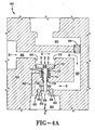
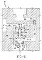
- FIGS. 4 , 4A , and 5 an exemplary first embodiment of the height control valve of the present invention is schematically shown and is indicated generally at 60.
- the general external appearance, control arm disposition and operation, and installation of height control valve 60 of the present invention are similar to that of prior art control valve 34 shown in FIG 1 , with the principal difference being the internal structure and function of the inventive height control valve for regulating the rate of its air exhaust Therefore, only the differences between height control valve 60 of the present invention and prior art height control valve 34 now will be described
- prior art height control valve 34 includes an exhaust orifice that is a generally straight-walled orifice (not shown) pneumatically connected to exhaust conduit 46
- height control valve 60 of the present invention includes a throttle assembly 62 that is pneumatically connected to an exhaust conduit (not shown) which enables regulation of the rate of air exhaust of the height control valve.
- FIG. 4 height control valve 60 and throttle assembly 62 are shown in a state when a vehicle on which they are used is significantly loaded with freight, whereby an increased load is placed on air springs 24 and causes compression of one or more of the air springs ( FIG 1 ). As a result, control lever 48 is urged upwardly into fill position B ( FIG.
- a valve baffle 99 is urged into a valve exhaust conduit 90, and air is supplied to air springs 24 from the air reservoir via air reservoir conduit 38 ( FIG. 2 ), a valve air reservoir conduit 95, a valve air spring conduit 96, and air spring conduits 42 ( FIG. 2 ), as indicated by arrows F', in order to maintain the vehicle at design ride height.
- Throttle assembly 62 includes a throttle assembly body 64 that preferably is an integral part of height control valve 60, or may alternatively be a discrete unit, in which a cylinder 66 is formed A piston 68 is disposed in cylinder 66 and an air pressure within height control valve 60, indicated by arrows D, compresses the piston in the cylinder An O-ring 70 is secured about the outer diameter of piston 68 to prevent air from passing between the walls of the piston and cylinder 66, thereby enabling efficient compression of the piston.
- height control valve 60 is activated and exhausts air from one or more of air springs 24 in order to lower axle/suspension system 10 to the design ride height. More particularly, control lever 48 is now urged downwardly into exhaust position C and valve baffle 99 is urged into valve air reservoir conduit 95 allowing air from air springs 24 to exhaust to atmosphere More specifically, during exhaustion, pressurized air from air springs 24 passes through air spring conduits 42 ( FIG.
- air pressure D causes throttle assembly 62 to restrict air flow out of the height control valve when the vehicle is loaded with freight and when control lever 48 is in the exhaust position C.
- air pressure D compresses piston 68, which is operatively connected to a plunger 72.
- Plunger 72 passes through a chamber 74 formed in throttle assembly body 64 and which is in communication with cylinder 66 More specifically, a spring 75 preferably is disposed in chamber 74 about plunger 72, and biases piston 68 in the direction of and into contact with a positive stop 77 when there is little or no air pressure in throttle assembly 62
- increased air pressure D is present, such as when the vehicle is loaded with freight, the increased air pressure overcomes the bias of spring 75, urging piston 68 in the direction of chamber 74, which in turn compresses the spring Plunge 72 extends through a plunger opening 76 that is formed in throttle assembly body 64, and which is in communication with chamber 74.
- An O-ring 78 is secured to throttle assembly body 64 in plunger opening 76 to prevent air from flowing back into chamber 74.
- a vent channel 80 is formed in throttle assembly body 64 and also communicates with chamber 74 to provide a vent for the chamber, thereby allowing piston 68 to move.
- tapered ring 82 may be formed as an integral part of throttle assembly body 64.
- Tapered ring 82 is formed with a decreasing inner diameter facilitated by a tapered inner wall 86 of the ring, thereby defining a ling opening 88
- Plunger 72 preferably includes a generally constant outer diameter that is smaller than the minimum inner diameter of tapered ring 82; which enables the plunger to pass freely into ring opening 88, thereby in turn defining a space 89 between the plunger and ring wall 86.
- the effective size of space 89 between plunger 72 and the ring wall decreases as air pressure D increases. That is, when air pressure D is lower, plunger 72 does not extend completely into ring opening 88, and thus space 89 between the plunger and ring wall 86 is larger than when the air pressure increases, which urges the plunger further into the ring opening. In this manner, as air pressure D increases, plunger 72 is urged further into opening 88, and the decreasing inner diameter of tapered wall 86 thus decreases the effective size of space 89 between the plunger and the ring wall, the benefit of which will be described below.
- height control valve 60 also includes valve exhaust conduit 90 formed in throttle assembly body 64, through which air exhausted from air springs 24, represented by arrows E, passes Exhausted air E passes through valve exhaust conduit 90 into throttled space 89 provided between plunger 72 and tapered ring wall 86. Upon passing through space 89 and ling opening 88, exhausted air E passes into an exit chamber 94 formed in throttle assembly body 64 and which communicates with the ring opening, and then to exhaust conduit 46 ( FIG.. 1 ).
- height control valve 60 and its throttle assembly 62 thus prevents the undesirably rapid exhaustion of air from air springs 24 when the vehicle is loaded and the air springs are temporarily extended, reducing over-exhaustion of the air springs Reduction of over-exhaustion of air springs 24 in turn enables the air reservoir (not shown) to inflate the air springs more rapidly when required after the event causing such regulated exhaustion has passed, thereby enabling the vehicle to maintain the design ride height and reduce potential damage to axle/suspension system 10
- height control valve 60 and throttle assembly 62 are shown in a state when the vehicle is unloaded or lightly loaded, which reduces the load on air springs 24 ( FIG. 1 ) Since the load on air springs 24 is reduced, the air pressure in the air springs is reduced, which in turn reduces the late of air flow out of the air springs when height control valve 60 is activated to exhaust the air springs Since the air flow E' out of air springs 24 is reduced, the potential for over-exhaustion of the air springs is in turn reduced. Accordingly, height control valve 60 accounts for this and provides less of an air flow restriction, when compared to the loaded-vehicle condition shown in FIG 4A .
- the reduced air pressure in air springs 24 creates a reduced air pressure D' acting on piston 68
- the reduced air pressure D' provides comparatively less or no force on piston 68, which reduces or eliminates the movement of plunger 72.
- spring 75 moves to its biased or extended position, pushing piston 68 in the direction of and into contact with positive stop 77.
- reduced all pressure D' does not overcome the bias of spring 75, and piston 68 therefore does not urge plunger 72 in the direction of tapered ring 82, and the plunger does not extend into ring opening 88.
- the maximum exhaust opening size is available, thereby allowing more exhausted air E' to pass from air springs 24 through valve exhaust conduit 90 valve exit chamber 94, and out of exhaust conduit 46 to atmosphere.
- the present invention provides a height control valve 60 with a variable air exhaust rate that is based on vehicle load, to compensate for dynamic ride height drift.
- Height control valve 60 of the exemplary embodiment of the present invention regulates the rate of flow of air being exhausted from air springs 24 by automatically reducing or restricting its exhaust path when the vehicle is loaded. That is, throttle assembly 62 of height control valve 60 reduces the cross-sectional area of the exhaust path as air spring pressure increases due to the loaded state of the vehicle, thus reducing the exhaust flow rate.
- This structure and function of height control valve 60 and throttle assembly 62 thereby prevent the rapid escape of air from air springs 24 of a loaded vehicle when a maneuver is executed that extends the air springs, in turn reducing the possibility of over-exhaustion of the air springs Reduction of possible over-exhaustion of air springs 24 enables the vehicle air reservoir to inflate the air springs more rapidly when required, thus enabling the vehicle to maintain the design ride height and reduce potential damage to axle/suspension system 10.
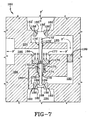
- throttle assembly such as placement of a second throttle assembly between and in fluid communication with the air reservoir and the air spring, as shown in FIGS. 6 and 7 , may also be used without affecting the overall concept of the invention.
- a throttle assembly may be disposed between and in fluid communication with the air reservoir and the air spring.
- FIGS 6 and 7 an exemplary second embodiment of the height control valve of the present invention is schematically shown and is indicated generally at 160.
- the general external appearance, control arm disposition and operation, and installation of height control valve 160 is similar to that of exemplary first embodiment height control valve 60, with the principal difference being the internal structure and function of the valve which includes a dual throttle assembly that can regulate both the rate of air flow from the air reservoir to the air spring when the height control valve is in a fill position, and the rate of air flow from the air spring to atmosphere when the height control valve is in an exhaust position.
- height control valve 160 in regulating the rate of air flow from the air spring to atmosphere when the height control valve is in an exhaust position is identical to the operation of height control valve 60 described in detail above, only the operation of height control valve 160 with respect to the regulation of the rate of air flow from the air reservoir to the air spring when the height control valve is in a fill position will now be described.
- An exemplary second embodiment of the present invention is shown in FIG.
- a first air spring/atmospheie throttle assembly 162 which is identical to throttle assembly 62, set forth above in height control valve 60, and comprising: a throttle assembly body 164, a cylinder 166, a piston 168, an o-ring 170, a first plunger 172, a chamber 174, a spring 175, a plunger opening 176, a positive stop 177, an o-ring 178, a vent channel 180, a tapered ring 182, a tapered inner wall 186, a ring opening 188, a space 189, a valve exhaust conduit 190, and an exit chamber 194.
- a second throttle assembly 162' is generally disposed between and in fluid communication with a valve air reservoir conduit 195 and a valve air spring conduit 196. This arrangement allows throttle assembly 162' of height control valve 160 to regulate or reduce the rate of flow of air from the air reservoir into the air spring when the valve is in a fill position, thereby preventing the air spring from inflating too rapidly and becoming overly extended when the vehicle is unloaded or lightly loaded, and thus allowing the vehicle to maintain design ride height
- height control valve 160 includes throttle assembly 162' operatively connected to piston 168 More specifically, a second plunger 172' generally opposes first plunger 172 and extends from piston 168. Second plunger 172' passes through a plunger opening 176' that is formed in a throttle assembly body 164'. An O-ring 178' is secured to throttle assembly body 164' in plunger opening 176' to prevent air from flowing through valve air reservoir conduit 195 into valve air spring conduit 196.
- control lever 48 is urged into fill position B, and a valve baffle 199 is urged into valve exhaust conduit 190, which in turn allows air F from the air reservoir to flow through air reservoir conduit 38 ( FIG. 2 ), to height control valve 160, through a tapered ring 182', into valve air reservoir conduit 195, into valve air spring conduit 196, into air spring conduits 42 ( FIG. 2 ), and into air springs 24 ( FIG. 2 ), thus filling the air springs and raising the vehicle frame to maintain design ride height.
- piston 168 is biased by spring 175 against positive stop 177 and urges plunger 172' in the direction of tapered ring 182' disposed in throttle assembly body 164'
- Tapered ring 182' is formed with a decreasing inner diameter facilitated by a tapered inner wall 186' of the ring, thereby defining a ring opening 188'.
- tapered ring 182' may be formed as an integral part of throttle assembly body 164'
- Plunger 172' preferably includes a generally constant outer diameter that is smaller than the minimum inner diameter of tapered ring 182', which enables the plunger to pass freely into ring opening 188', thereby in turn defining a space 189' between the plunger and ring wall 186'.
- height control valve 160 In this manner, the movement of plunger 172' intro ring opening 188', which increases as air pressure D' decreases, enables height control valve 160 to restrict the flow of air from the air reservoir to air springs 24 when the vehicle is unloaded or lightly loaded and executes a maneuver, such as a hard turn, which causes axle/suspension system 10 to articulate to a position that compresses air springs 24.
- This structure and function of height control valve 160 and its throttle assembly 162' thus prevents the undesirably rapid inflation of air springs 24 when the vehicle is unloaded or lightly loaded and the air springs are temporarily compressed, reducing over-inflation of the air springs. Reduction of over-inflation of air springs 24 in turn enables the vehicle to maintain the design ride height and reduces potential damage to the vehicle and to highway infrastructure.
- height control valve 160 and throttle assembly 162' are shown in a state when the vehicle is significantly loaded, which increases the load on air springs 24 ( FIG. 1 ). Because the load on air springs 24 is increased, the air pressure in the air springs is also increased, which in turn reduces the natural rate of flow F' from the air reservoir to the air springs when height control valve 160 is activated to fill the air springs, as the pressure differential between the air reservoir and the air spring is reduced.
- height control valve 160 accounts for this and provides less air flow restriction between the air reservoir and the air springs, when compared to the unloaded or lightly loaded vehicle situation shown in Fig. 6
- the increased air pressure in air springs 24 creates an increased air pressure D acting on piston 168.
- the increased air pressure D provides an increased force on piston 168, which overcomes the bias of spring 175, moving plunger 172' away from opening 188'. Without plunger 172' extending into ring opening 188', the maximum fill opening size is available, thereby allowing more air F' to pass from the air reservoir to the air springs.
- throttle assemblies 62, 162 and 162' of height control valves 60 and 160 may include a variable restriction that reacts proportionally to the load on air springs 24, or alternatively, the throttle assemblies may have discrete settings based on predetermined pressure levels, without affecting the overall concept of the invention.
- throttle assemblies 62, 162, and 162' may open or close based upon reference to the pressure differential between the vehicle air reservoir and the pressure in air springs 24, also without affecting the overall concept of the invention. It is contemplated that other types of throttle assemblies used to restrict air flow such as a butterfly or solenoid-type assemblies may be used without affecting the overall concept or operation of the invention.
- each vehicle axle/suspension assembly, or air spring, such as one height control valve per axle/suspension assembly or one height control valve per air spring, to provide an enhanced degree of height control for the vehicle, without affecting the overall concept of the invention This is especially important where very flexible axle/suspension systems are utilized.
- separate independent throttle assemblies may be used with one height control valve, such as a first independent throttle assembly between the air reservoir and the air spring to regulate air supply and a separate second independent throttle assembly between the air spring and atmosphere to regulate air exhaustion, without affecting the overall concept or operation of the invention.
- throttle assemblies may be separate from the height control valve, such as a remote throttle assembly that is pneumatically connected to the height control valve, without affecting the overall concept or operation of the invention.
- the invention also applies to other types of air-ride axle/suspension systems, such as other types of trailing arm and leading arm air-ride suspension assemblies.
- the invention applies to various types of frames used for heavy-duty vehicles, including primary frames that do not support a subframe and primary frames and/or floor structures that do support a subframe
- the subframe can be non-movable or movable, the latter being commonly referred to as a slider box.
- the improved height control valve for an air-ride axle/suspension system of a heavy-duty vehicle is simplified, provides an effective, safe, inexpensive, and efficient structure which achieves all the enumerated objectives, provides for eliminating difficulties encountered with prior art height control valves for heavy-duty vehicle air-ride axle/suspension systems, and solves problems and obtains new results in the art
Landscapes
- Engineering & Computer Science (AREA)
- Mechanical Engineering (AREA)
- Vehicle Body Suspensions (AREA)
Claims (10)
- Höhenregelungsventilanordnung für eine Luftfeder (24) eines luftgefederten Achs-/Aufhängungssystems (10) eines Schwerlastfahrzeugs, umfassend ein Höhenregelungsventil (60; 160) mit(a) einem Ventilkörper, der in Fluidkommunikation mit der Luftfeder (24), einem Luftzufuhrbehälter und der Atmosphäre steht;(b) Betätigungsmitteln (45), die mit dem Ventilkörper und dem Achs-/Aufhängungssystem (10) verbunden sind und betätigbar sind, um das Höhenregelungsventil (60; 160) zu betätigen, um im Allgemeinen ein vorbestimmtes Fahrzeugniveau aufrecht zu erhalten und insbesondere, wenn die Luftfeder (24) während des Fahrzeugbetriebs in gedehntem Zustand ist, wobei das Fahrzeug sich in beladenem Zustand befindet, um das Ventil (60) zu betätigen, um Fluid aus der Luftfeder (24) abzulassen;(c) eine Ablassdrosselanordnung (62; 162), die betätigbar ist, um die Rate des Ablassstroms des Fluids aus der Luftfeder (24) zu regulieren, und einen Ablassdrosselanordnungskörper (64) aufweist, der entweder in den Ventilkörper des Höhenreglungsventils (60; 160) integriert ist oder von diesem getrennt vorliegt;dadurch gekennzeichnet, dass
die Ablassdrosselanordnung (62; 162) betätigbar ist, um den Ablassstrom in Abhängigkeit vom Druck der Luftfeder zu regulieren, sodass eine Steigerung des Luftfederdrucks bewirkt, dass die Ablassdrosselanordnung (62; 162) den Ablassstrom aus der Luftfeder (24) einschränkt. - Höhenregulierungsventilanordnung nach Anspruch 1, worin die Ablassdrosselanordnung (62; 162) Folgendes umfasst:- eine in dem Ablassdrosselanordnungskörper (64) ausgebildete Kammer;- einen Tauchkolben (72; 172), der in der Kammer (74; 174) angeordnet ist, und- einen sich verjüngenden Ring (82, 86; 182, 186), der mit dem Ablassdrosselanordnungskörper (64; 164) verbunden ist oder einstückig mit diesem ausgebildet ist und einen sich verjüngenden Innendurchmesser aufweist,wobei die Ablassdrosselanordnung (62; 162) betätigbar ist, indem ein Ende des Tauchkolbens in den sich verjüngenden Innendurchmesser des Rings (82, 86; 182; 186) gedrückt wird, um den Ablassstrom einzuschränken, wenn der Druck in der Luftfeder (24) erhöht ist.
- Höhenregulierungsventilanordnung nach Anspruch 2, worin ein Kolben (68; 168) an dem Tauchkolben (72; 172) angebracht ist und der Druck auf den Kolben wirkt.
- Höhenregulierungsventilanordnung nach einem der vorangegangenen Ansprüche, worin die Ablassdrosselanordnung (62; 162) ein integraler Bestandteil des Ventilkörpers ist.
- Höhenregulierungsventilanordnung für eine Luftfeder (24) eines luftgefederten Achs-/Aufhängungssystems (10) eines Schwerlastfahrzeugs, umfassend ein Höhenregulierungsventil (160) mit(a) einem Ventilkörper, der in Fluidkommunikation mit der Luftfeder (24), einem Luftzufuhrbehälter und der Atmosphäre steht;(b) Betätigungsmitteln (45), die mit dem Ventilkörper und dem Achs-/Aufhängungssystem (10) verbunden sind und betätigbar sind, um das Höhenregelungsventil (160) zu betätigen, um im Allgemeinen ein vorbestimmtes Fahrzeugniveau aufrecht zu erhalten und insbesondere, wenn die Luftfeder (24) während des Fahrzeugbetriebs in zusammengedrücktem Zustand ist, wobei das Fahrzeug sich in unbeladenem Zustand befindet, um das Ventil (160) zu betätigen, um Fluid aus dem Luftzufuhrbehälter in die Luftfeder (24) zu füllen;(c) eine Befüllungsdrosselanordnung (162'), die betätigbar ist, um die Rate des Befüllungsstroms des Fluids aus dem Luftzufuhrbehälter in die Luftfeder (24) zu regulieren, und einen Befüllungsdrosselanordnungskörper (164') aufweist, der entweder in den Ventilkörper des Höhenreglungsventils (160) integriert ist oder von diesem getrennt vorliegt;dadurch gekennzeichnet, dass
die Befüllungsdrosselanordnung (62; 162) betätigbar ist, um den Befüllungsstrom in Abhängigkeit vom Druck der Luftfeder zu regulieren, sodass ein Absinken des Luftfederdrucks bewirkt, dass die Befüllungsdrosselanordnung (162') den Befüllungsstrom in die Luftfeder (24) einschränkt. - Höhenregelungsventilanordnung nach Anspruch 5, worin die Befüllungsdrosselanordnung (162') Folgendes umfasst:- einen Tauchkolben (172'), der in einer Öffnung in dem Befüllungsdrosselanordnungskörper (164') angeordnet ist, und- einen sich verjüngenden Ring (182', 186'), der mit dem Befüllungsdrosselanordnungskörper (164') verbunden ist oder einstückig mit diesem ausgebildet ist und einen sich verjüngenden Innendurchmesser aufweist,wobei die Befüllungsdrosselanordnung (162') betätigbar ist, indem ein Ende des Tauchkolbens in den sich verjüngenden Innendurchmesser des Rings (182'; 186') gedrückt wird, um den Befüllungsstrom einzuschränken, wenn der Druck in der Luftfeder (24) reduziert ist.
- Höhenregulierungsventilanordnung nach Anspruch 6, worin ein Kolben (168) an dem Tauchkolben (172') angebracht ist und der Druck auf den Kolben wirkt.
- Höhenregulierungsventilanordnung nach Anspruch 5, 6 oder 7, worin die Befüllungsdrosselanordnung (162') ein integraler Bestandteil des Ventilkörpers ist.
- Höhenregulierungsventilanordnung mit einer Befüllungsdrosselanordnung nach einem der Ansprüche 5 bis 8, das zusätzlich dazu eine Ablassdrosselanordnung nach einem der Ansprüche 1 bis 4 aufweist.
- Höhenregulierungsventilanordnung nach einem der vorangegangenen Ansprüche, worin das Betätigungsmittel (48) ein Steuerhebel ist.
Applications Claiming Priority (2)
| Application Number | Priority Date | Filing Date | Title |
|---|---|---|---|
| US73374505P | 2005-11-04 | 2005-11-04 | |
| PCT/US2006/060476 WO2007142689A2 (en) | 2005-11-04 | 2006-11-02 | Height control valve for vehicle axle/suspension system |
Publications (3)
| Publication Number | Publication Date |
|---|---|
| EP1943115A2 EP1943115A2 (de) | 2008-07-16 |
| EP1943115B1 true EP1943115B1 (de) | 2010-06-09 |
| EP1943115B8 EP1943115B8 (de) | 2010-07-21 |
Family
ID=38650032
Family Applications (1)
| Application Number | Title | Priority Date | Filing Date |
|---|---|---|---|
| EP20060851317 Active EP1943115B8 (de) | 2005-11-04 | 2006-11-02 | Höhenkontrollventil für ein fahrzeugachsen-/aufhängungssystem |
Country Status (10)
| Country | Link |
|---|---|
| US (1) | US7621537B2 (de) |
| EP (1) | EP1943115B8 (de) |
| AT (1) | ATE470586T1 (de) |
| AU (1) | AU2006344346B2 (de) |
| BR (1) | BRPI0617440A2 (de) |
| CA (1) | CA2614847C (de) |
| DE (1) | DE602006014856D1 (de) |
| MX (1) | MX2008001348A (de) |
| NZ (1) | NZ566438A (de) |
| WO (1) | WO2007142689A2 (de) |
Families Citing this family (7)
| Publication number | Priority date | Publication date | Assignee | Title |
|---|---|---|---|---|
| WO2009100089A1 (en) * | 2008-02-04 | 2009-08-13 | Hendrickson Usa, L.L.C. | Multi-stage height control valve including position sensitive pilot signal and pressure boost for vehicle air springs |
| TR201820951T4 (tr) * | 2011-06-14 | 2019-01-21 | Hendrickson Usa Llc | Aks/süspansiyon sistemleri için yükseklik kontrol valfı donanımı. |
| US9139061B2 (en) * | 2013-04-03 | 2015-09-22 | Watson & Chalin Manufacturing, Inc. | Vehicle suspension system with reservoir for air spring damping |
| DE112014004144T5 (de) | 2013-09-10 | 2016-07-07 | Firestone Industrial Products Company, Llc | Füllventilhalterung für ein Luftfederungssystem an einem Fahrzeug |
| US9517674B2 (en) * | 2014-06-24 | 2016-12-13 | Hendrickson Usa, L.L.C. | Pneumatic control system for a heavy-duty vehicle |
| WO2018039101A1 (en) * | 2016-08-22 | 2018-03-01 | Stemco Products, Inc. | Pneumatic anti-roll system |
| US11554627B2 (en) | 2021-06-15 | 2023-01-17 | Stephen Ray Lynn | Vehicle height control system |
Family Cites Families (13)
| Publication number | Priority date | Publication date | Assignee | Title |
|---|---|---|---|---|
| US2925284A (en) * | 1957-03-07 | 1960-02-16 | Ford Motor Co | Motor vehicle air suspension system |
| US3021151A (en) * | 1957-04-12 | 1962-02-13 | Ford Motor Co | Motor vehicle air suspension system and flow rate control valve |
| US2989983A (en) * | 1957-09-13 | 1961-06-27 | Bendix Westinghouse Automotive | Load control valve for vehicle air springs |
| US2967064A (en) * | 1957-09-13 | 1961-01-03 | Bendix Westinghouse Automotive | Load control valve for vehicle air springs |
| US2939725A (en) * | 1958-04-30 | 1960-06-07 | Gen Motors Corp | Flow ratio blocker valve for air suspension |
| GB911492A (en) * | 1958-06-21 | 1962-11-28 | Dunlop Rubber Co | Vehicle suspension systems |
| US3082018A (en) * | 1958-06-23 | 1963-03-19 | Borg Warner | Leveling valve mechanism |
| US2986404A (en) * | 1958-10-02 | 1961-05-30 | Borg Warner | Control valve for air suspension system |
| DE19923456C5 (de) * | 1999-05-21 | 2008-07-24 | Knorr-Bremse Systeme für Nutzfahrzeuge GmbH | Niveauregelventil für die Luftfederung von Fahrzeugen, insbesondere Nutzfahrzeugen |
| AU7069900A (en) * | 1999-08-24 | 2001-03-19 | Holland Neway International, Inc. | Trailing arm suspension and height control valve therefor |
| US6412789B1 (en) | 2002-01-04 | 2002-07-02 | The Boler Company | Semi-trailer suspension air spring control system |
| WO2009018155A1 (en) * | 2007-07-31 | 2009-02-05 | Hendrickson Usa, L.L.C. | Pneumatic proportioning system for vehicle air springs |
| WO2009100089A1 (en) * | 2008-02-04 | 2009-08-13 | Hendrickson Usa, L.L.C. | Multi-stage height control valve including position sensitive pilot signal and pressure boost for vehicle air springs |
-
2006
- 2006-11-02 NZ NZ566438A patent/NZ566438A/en not_active IP Right Cessation
- 2006-11-02 US US11/555,840 patent/US7621537B2/en active Active
- 2006-11-02 MX MX2008001348A patent/MX2008001348A/es active IP Right Grant
- 2006-11-02 CA CA 2614847 patent/CA2614847C/en active Active
- 2006-11-02 EP EP20060851317 patent/EP1943115B8/de active Active
- 2006-11-02 BR BRPI0617440-0A patent/BRPI0617440A2/pt not_active IP Right Cessation
- 2006-11-02 DE DE200660014856 patent/DE602006014856D1/de active Active
- 2006-11-02 WO PCT/US2006/060476 patent/WO2007142689A2/en active Application Filing
- 2006-11-02 AT AT06851317T patent/ATE470586T1/de not_active IP Right Cessation
- 2006-11-02 AU AU2006344346A patent/AU2006344346B2/en active Active
Also Published As
| Publication number | Publication date |
|---|---|
| AU2006344346B2 (en) | 2010-09-23 |
| WO2007142689B1 (en) | 2008-05-02 |
| CA2614847C (en) | 2012-10-30 |
| AU2006344346A1 (en) | 2007-12-13 |
| MX2008001348A (es) | 2008-03-14 |
| ATE470586T1 (de) | 2010-06-15 |
| WO2007142689A3 (en) | 2008-02-14 |
| CA2614847A1 (en) | 2007-12-13 |
| EP1943115A2 (de) | 2008-07-16 |
| EP1943115B8 (de) | 2010-07-21 |
| NZ566438A (en) | 2011-03-31 |
| BRPI0617440A2 (pt) | 2011-07-26 |
| WO2007142689A2 (en) | 2007-12-13 |
| US20070102895A1 (en) | 2007-05-10 |
| US7621537B2 (en) | 2009-11-24 |
| DE602006014856D1 (de) | 2010-07-22 |
Similar Documents
| Publication | Publication Date | Title |
|---|---|---|
| US8047551B2 (en) | Multi-stage height control valve including position sensitive pilot signal and pressure boost for vehicle air springs | |
| US7841608B2 (en) | Pneumatic proportioning system for vehicle air springs | |
| EP1943115B1 (de) | Höhenkontrollventil für ein fahrzeugachsen-/aufhängungssystem | |
| US8523191B2 (en) | Height control valve assembly for axle/suspension systems | |
| EP1456044B1 (de) | Federungsteuerungssystem für eine fahrzeug-liftachse | |
| US8459666B2 (en) | Side-beam lift assembly for heavy-duty vehicles | |
| US9517674B2 (en) | Pneumatic control system for a heavy-duty vehicle | |
| US20040061292A1 (en) | Articulation compensated hydraulic suspension system | |
| BR112021005693A2 (pt) | regulador acionado por piloto com pressão de distribuição mínima ajustável | |
| US20190337349A1 (en) | Pneumatic control system for vehicles and other loaded structures | |
| EP0633849B1 (de) | Verbesserungen anhilfsaufhängungssystemen | |
| EP0517546A1 (de) | Verbesserung an und bei Fahrzeugfederungen | |
| KR20010003110A (ko) | 자동차의 공기현가장치 | |
| NZ617436B2 (en) | Height control valve assembly for axle/suspension systems |
Legal Events
| Date | Code | Title | Description |
|---|---|---|---|
| PUAI | Public reference made under article 153(3) epc to a published international application that has entered the european phase |
Free format text: ORIGINAL CODE: 0009012 |
|
| 17P | Request for examination filed |
Effective date: 20080204 |
|
| AK | Designated contracting states |
Kind code of ref document: A2 Designated state(s): AT BE BG CH CY CZ DE DK EE ES FI FR GB GR HU IE IS IT LI LT LU LV MC NL PL PT RO SE SI SK TR |
|
| AX | Request for extension of the european patent |
Extension state: AL BA HR MK RS |
|
| 17Q | First examination report despatched |
Effective date: 20081009 |
|
| GRAP | Despatch of communication of intention to grant a patent |
Free format text: ORIGINAL CODE: EPIDOSNIGR1 |
|
| GRAS | Grant fee paid |
Free format text: ORIGINAL CODE: EPIDOSNIGR3 |
|
| GRAA | (expected) grant |
Free format text: ORIGINAL CODE: 0009210 |
|
| AK | Designated contracting states |
Kind code of ref document: B1 Designated state(s): AT BE BG CH CY CZ DE DK EE ES FI FR GB GR HU IE IS IT LI LT LU LV MC NL PL PT RO SE SI SK TR |
|
| REG | Reference to a national code |
Ref country code: CH Ref legal event code: EP |
|
| REG | Reference to a national code |
Ref country code: CH Ref legal event code: PK Free format text: DIE BENENNUNG CH/LI WURDE VOR DER ERTEILUNG ZURUECKGENOMMEN. |
|
| REG | Reference to a national code |
Ref country code: IE Ref legal event code: FG4D |
|
| RBV | Designated contracting states (corrected) |
Designated state(s): BE DE FR GB NL SE |
|
| REF | Corresponds to: |
Ref document number: 602006014856 Country of ref document: DE Date of ref document: 20100722 Kind code of ref document: P |
|
| REG | Reference to a national code |
Ref country code: NL Ref legal event code: T3 |
|
| REG | Reference to a national code |
Ref country code: SE Ref legal event code: TRGR |
|
| PLBE | No opposition filed within time limit |
Free format text: ORIGINAL CODE: 0009261 |
|
| STAA | Information on the status of an ep patent application or granted ep patent |
Free format text: STATUS: NO OPPOSITION FILED WITHIN TIME LIMIT |
|
| REG | Reference to a national code |
Ref country code: DE Ref legal event code: R097 Ref document number: 602006014856 Country of ref document: DE Effective date: 20110309 |
|
| PGFP | Annual fee paid to national office [announced via postgrant information from national office to epo] |
Ref country code: BE Payment date: 20121129 Year of fee payment: 7 Ref country code: GB Payment date: 20121025 Year of fee payment: 7 |
|
| PGFP | Annual fee paid to national office [announced via postgrant information from national office to epo] |
Ref country code: FR Payment date: 20131118 Year of fee payment: 8 |
|
| BERE | Be: lapsed |
Owner name: HENDRICKSON INTERNATIONAL CORP. Effective date: 20131130 |
|
| GBPC | Gb: european patent ceased through non-payment of renewal fee |
Effective date: 20131102 |
|
| PG25 | Lapsed in a contracting state [announced via postgrant information from national office to epo] |
Ref country code: BE Free format text: LAPSE BECAUSE OF NON-PAYMENT OF DUE FEES Effective date: 20131130 |
|
| PG25 | Lapsed in a contracting state [announced via postgrant information from national office to epo] |
Ref country code: GB Free format text: LAPSE BECAUSE OF NON-PAYMENT OF DUE FEES Effective date: 20131102 |
|
| PGFP | Annual fee paid to national office [announced via postgrant information from national office to epo] |
Ref country code: NL Payment date: 20141126 Year of fee payment: 9 |
|
| REG | Reference to a national code |
Ref country code: FR Ref legal event code: ST Effective date: 20150731 |
|
| PG25 | Lapsed in a contracting state [announced via postgrant information from national office to epo] |
Ref country code: FR Free format text: LAPSE BECAUSE OF NON-PAYMENT OF DUE FEES Effective date: 20141201 |
|
| REG | Reference to a national code |
Ref country code: NL Ref legal event code: MM Effective date: 20151201 |
|
| PG25 | Lapsed in a contracting state [announced via postgrant information from national office to epo] |
Ref country code: NL Free format text: LAPSE BECAUSE OF NON-PAYMENT OF DUE FEES Effective date: 20151201 |
|
| PGFP | Annual fee paid to national office [announced via postgrant information from national office to epo] |
Ref country code: SE Payment date: 20191127 Year of fee payment: 14 |
|
| REG | Reference to a national code |
Ref country code: DE Ref legal event code: R082 Ref document number: 602006014856 Country of ref document: DE Representative=s name: MEWBURN ELLIS LLP, DE Ref country code: DE Ref legal event code: R081 Ref document number: 602006014856 Country of ref document: DE Owner name: HENDRICKSON INTERNATIONAL CORP., SCHAUMBURG, US Free format text: FORMER OWNER: HENDRICKSON INTERNATIONAL CORP., ITASCA, ILL., US |
|
| REG | Reference to a national code |
Ref country code: SE Ref legal event code: EUG |
|
| PG25 | Lapsed in a contracting state [announced via postgrant information from national office to epo] |
Ref country code: SE Free format text: LAPSE BECAUSE OF NON-PAYMENT OF DUE FEES Effective date: 20201103 |
|
| P01 | Opt-out of the competence of the unified patent court (upc) registered |
Effective date: 20230512 |
|
| PGFP | Annual fee paid to national office [announced via postgrant information from national office to epo] |
Ref country code: DE Payment date: 20231129 Year of fee payment: 18 |