EP1941856B1 - Wheelchair seat back mount assembly and wheelchair therewith - Google Patents
Wheelchair seat back mount assembly and wheelchair therewith Download PDFInfo
- Publication number
- EP1941856B1 EP1941856B1 EP07025155A EP07025155A EP1941856B1 EP 1941856 B1 EP1941856 B1 EP 1941856B1 EP 07025155 A EP07025155 A EP 07025155A EP 07025155 A EP07025155 A EP 07025155A EP 1941856 B1 EP1941856 B1 EP 1941856B1
- Authority
- EP
- European Patent Office
- Prior art keywords
- relation
- seat back
- assembly
- portions
- attachable
- Prior art date
- Legal status (The legal status is an assumption and is not a legal conclusion. Google has not performed a legal analysis and makes no representation as to the accuracy of the status listed.)
- Active
Links
Images


Classifications
-
- A—HUMAN NECESSITIES
- A61—MEDICAL OR VETERINARY SCIENCE; HYGIENE
- A61G—TRANSPORT, PERSONAL CONVEYANCES, OR ACCOMMODATION SPECIALLY ADAPTED FOR PATIENTS OR DISABLED PERSONS; OPERATING TABLES OR CHAIRS; CHAIRS FOR DENTISTRY; FUNERAL DEVICES
- A61G5/00—Chairs or personal conveyances specially adapted for patients or disabled persons, e.g. wheelchairs
- A61G5/10—Parts, details or accessories
- A61G5/12—Rests specially adapted therefor, e.g. for the head or the feet
-
- A—HUMAN NECESSITIES
- A61—MEDICAL OR VETERINARY SCIENCE; HYGIENE
- A61G—TRANSPORT, PERSONAL CONVEYANCES, OR ACCOMMODATION SPECIALLY ADAPTED FOR PATIENTS OR DISABLED PERSONS; OPERATING TABLES OR CHAIRS; CHAIRS FOR DENTISTRY; FUNERAL DEVICES
- A61G5/00—Chairs or personal conveyances specially adapted for patients or disabled persons, e.g. wheelchairs
- A61G5/10—Parts, details or accessories
- A61G5/1056—Arrangements for adjusting the seat
- A61G5/1067—Arrangements for adjusting the seat adjusting the backrest relative to the seat portion
-
- A—HUMAN NECESSITIES
- A61—MEDICAL OR VETERINARY SCIENCE; HYGIENE
- A61G—TRANSPORT, PERSONAL CONVEYANCES, OR ACCOMMODATION SPECIALLY ADAPTED FOR PATIENTS OR DISABLED PERSONS; OPERATING TABLES OR CHAIRS; CHAIRS FOR DENTISTRY; FUNERAL DEVICES
- A61G5/00—Chairs or personal conveyances specially adapted for patients or disabled persons, e.g. wheelchairs
- A61G5/10—Parts, details or accessories
- A61G5/12—Rests specially adapted therefor, e.g. for the head or the feet
- A61G5/122—Rests specially adapted therefor, e.g. for the head or the feet for the back
-
- A—HUMAN NECESSITIES
- A61—MEDICAL OR VETERINARY SCIENCE; HYGIENE
- A61G—TRANSPORT, PERSONAL CONVEYANCES, OR ACCOMMODATION SPECIALLY ADAPTED FOR PATIENTS OR DISABLED PERSONS; OPERATING TABLES OR CHAIRS; CHAIRS FOR DENTISTRY; FUNERAL DEVICES
- A61G2210/00—Devices for specific treatment or diagnosis
- A61G2210/10—Devices for specific treatment or diagnosis for orthopedics
Definitions
- the invention relates to an assembly for mounting a seat back shell to a wheelchair seat back cane according to the pre-amble of claim 1.
- WO 02/36061 A2 relates to a seatback mounting system that securely self-locks, but unlocks easily with a simple positive action by the user to release the back system from the wheelchair.
- the seatback can be conveniently released from its mountings by a simple forward rotation through a prescribed angle in conjunction with a lifting action.
- the seatback system comprises, in part, a rigid shell seatback having mounted thereto a first pair of laterally extending pin assemblies and a second pair of laterally extending pin assemblies, where each pin assembly has an extending pin portion.
- the system also comprises a first pair of mounting clips and a second pair of mounting clips.
- the first pair of mounting clips selectively retains the first pair of pins w-hile the second pair of mounting clips temporarily retains the second pair of pins so long as the first pair of extending pins is secured by the first pair of mounting clips.
- the first pair of mounting clips are preferably self-locking and manually releasing, and are mounted to an upper portion of the wheelchair's vertical posts or canes.
- the second pair of mounting clips are preferably "U"-shaped members mounted to a lower portion of a wheelchair's vertical posts or canes wherein the web portion of the "U" receives the pin.
- This invention relates to an assembly for mounting a seat back shell to a seat back cane of a wheelchair as defined in claim 1.
- the assembly comprises a first portion attachable to the seat back cane and a second portion attachable to the seat back shell.
- the portions mate to form a point of attachment by aligning one of the portions with the other portion and displacing one of the portions in relation to the other portion.
- Fig. 1 is a partially exploded, environmental perspective view of a seat back mount assembly.
- Fig. 2 is an enlarged-scale, exploded perspective view of the assembly shown in Fig. 1 .
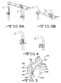
- Fig. 3 is an enlarged-scale, exploded perspective view of an adjustable clamp of the assembly shown in Fig. 1 .
- Fig. 4 is a reduced-scale, environmental partial rear perspective view of the assembly shown in Fig. 1 .
- Figs. 5A-5B are perspective views of a seat back being located and installed with the seat back mount assembly as shown in Fig. 1 .
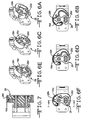
- Figs. 6A-6F are enlarged, elevational views of a mounting block and a c-shaped mounting bracket of the assembly shown in Fig. 1 at various stages of cooperation.
- Fig. 7 is a cross-sectional view of the mounting block and the c-shaped mounting bracket taken along the lines 7-7 in Fig. 6F .
- Fig. 8 is an enlarged-scale, exploded perspective view of a bottom hook for use with the assembly shown in Fig. 1 .
- Fig. 1 a partially exploded, environmental perspective view of a wheelchair seat back mount assembly 10.
- the assembly 10 may be comprised of two portions, a first portion, generally indicated at 12, that may be attachable in relation to the wheelchair seat back canes 14 and a second portion, generally indicated at 16, that may be attachable in relation to the wheelchair seat back shell 18. These two portions 12, 16 may mate to form an easy-to-use assembly.
- the first portion 12 may include a clamp bracket having a first part, which may be in the form of a tube clamp plate 20, and a second part, which may be in the form of a tube clamp hinge 22a that may cooperate with the tube clamp plate 20.
- the tube clamp plate 20 may have a relatively planar main body portion 20a and a curved or hooked portion, generally indicated at 20b, extending from the main body portion 20a. Spaced fingers 20c may extend from the hooked portion 20b. Aligning holes 20d in the fingers 20c may receive a dowel pin 24, which may fit tightly in the holes 20d.
- the tube clamp hinge 22 may have a curved or hooked portion 22a, which may be similar to the hook portion 20b of the tube clamp plate 20.
- a tab 22b may extend from the hooked portion 22a.
- the tab 22b may be sized to fit between the fingers 20c.
- a groove 22c on the tabs may engage the dowel pin 24 to form a connection between the tube clamp plate 20 and the tube clamp hinge 22.
- the engaging groove 22c and dowel pin 24, in effect, may form a hinge.
- Multiple grooves, such as the two grooves 22c shown, may be provided for selective engagement with the dowel pin 24 to adjust the size of the clamp bracket, as will become apparent in the description that follows.
- a tongue 22d may extend from the hooked portion 22a, opposite the tab 22b.
- One or more bores 22e may pass the tongue 22d.
- One or more fasteners 26, such as the cap screws shown, may pass through the bores 22e, which may be counter bores, in the tongue 22d and may be threaded into aligning threaded holes 20e in the main body portion 20a of the clamp bracket to fasten the tongue 22d of the tube clamp hinge 22 to the main body portion 20a of the tube clamp plate 20.
- the fasteners 26 may be threaded into nuts, such as the lock nuts shown, on the opposite side (i.e., the blind side when viewing Fig. 2 ) of the main body portion 20a.
- the nuts may be recessed in hexagonal holes in the main body portion 20a so that the hexagonal holes prevent the nuts from turning.
- a mounting block 28 may be supported in relation to the clamp bracket, such as in relation to the tube clamp plate 20 or in relation to the main body portion 20a of the tube clamp plate 20.
- the mounting block 28 may be mounted with one or more fasteners 30, such as the cap screws shown.
- one or more bores 20g which may be counter bores, may be provided through the main body portion 20a and may align with holes 28a, 28b through the mounting block 28.
- the fasteners 30 may pass through the bores 20g in the main body portion 20a and further through aligning holes 28a, 28b in the mounting block 28.
- the fasteners 30 may then be threaded into nuts, such as the lock nuts shown, on the opposite side of the mounting block 28.
- the nuts may be recessed in holes in the mounting block 28 (i.e., the blind side when viewing Fig. 2 ).
- the holes may be dimensioned and configured to prevent the nuts from turning.
- the main body portion 20a may have a plurality of bores 20g, including three sets or pairs of bores. Each pair may be arranged to support the seat back shell 18 at a different angle. For example, the three pairs of bores may support the seat back shell 18 at 0, 5, and 10 degrees (i.e., relative to vertical when viewing Fig. 1 ).
- the main body portion 20a may be provided with indicia, as shown in Fig. 3 , corresponding with each pair of bores to indicate the angular disposition of the seat back shell 18 if a corresponding pair of bores is used.
- the mounting block 28 may have two holes 28a, 28b. Two fasteners 30 may pass through the two holes 28a, 28b. One fastener 30 passing through one hole 28a may function as a pivot. The other fastener 30 may pass through the other hole 28b, which may be curved or arcuate in shape. In this way, the mounting block 28 may be able to pivot on the one fastener 30 as the mounting block 28 moves in relation to the other fastener 30 due to the provision of the curved or arcuate shaped hole 28b.
- the exemplary mounting block 28 may have a substantially circular shaped portion 28c and a substantially oval or kidney shaped portion 28d separated by a necked-down portion 28e, when viewed from a point parallel or along the axes A1, A2 of the holes 28a, 28b therethrough.
- the hole 28a for the fastener 30 that may function as a pivot passes through the circular portion 28c.
- the arcuate shaped hole 28b may pass through the substantially oval or kidney shaped portion 28d.
- the mounting block 28 may have a first or outer portion 28f and a second or inner portion 28g, which may be reduced in size so as to be smaller in dimension when viewed from a point transverse or crosswise from the axes A1, A2 of the holes 28a, 28b therethrough.
- the larger outer portion 28f may form a first flange that extends radially outward in relation to the inner portion 28g.
- a substantially pointed guide 28h may extend (upwardly when viewing Fig. 2 ) from the top of the flange.
- the second portion 16 of the assembly 10 may include a substantially C-shaped mounting bracket having a first or outer portion 16a and a second or inner portion 16b, which may be of a different size or dimension relative to the outer portion 16a so that the inner portion 16b may form a second flange that may extend radially inward in relation to the outer portion 16a.
- the C-shaped mounting bracket may define a radial opening 16d and the flange may define an axial opening 16e.
- the radial opening 16d may permit passage of the mounting block 28 when aligned or oriented in a first orientation and prevents passage of the mounting block 28 when displaced or oriented in a second orientation.
- the axial opening 16e may restrict axial passage of the mounting block 28 when in the second orientation.
- the outer portion 16a may be dimensioned and configured to be substantially complementary in shape to the outer portion 28f of the mounting block 28, and may include, for example, a region, such as the radial opening 16dor channel 16d shown in Fig. 7 , into which the pointed guide 28h may be inserted.
- the inner portion 16b may be dimensioned and configured to be substantially complementary in shape to the outer portion 28f of the mounting block 28.
- the two flanges may cooperate to form an attachment between the mounting block 28 and the C-shaped mounting bracket when oriented in a certain orientation (e.g., the first orientation) in relation to one another, as will become more apparent in the description that follows.
- the exemplary C-shaped mounting bracket may be mounted in relation to the seat back shell 18 by a top mount bracket 32.
- the exemplary top mount bracket 32 is a substantially L-shaped or V-shaped bracket having one or more holes or slots 32a therein that permit adjustment, such as lateral adjustment, of the top mount bracket 32 in relation to the seat back shell 18.
- the C-shaped mounting bracket may have one or more bores 16c, such as the counter bores shown, passing therethrough.
- the top mount bracket 32 may have threaded holes 32b that may align with the bores 16c.
- Fasteners 38 such as the cap screws shown, may pass through the bores 16c and be threaded into the holes 32b to fasten the C-shaped mounting bracket to the top mount bracket 32.
- the top mount bracket 32 may, in turn, be fastened to the seat back shell 18 in any suitable manner, such as via the stud plate 40, washers 39, and nuts 41 (e.g., locknuts) shown.
- a mounting block 28 is shown fastened in relation to each seat cane 14 and a C-shaped mounting bracket is fastened in relation to each side of the seat back shell 18.
- An attachment may be formed between each mounting block 28 and a corresponding C-shaped mounting bracket. This may form two points of attachment of the seat back shell 18 in relation to the seat back canes 14.
- the seat back shell 18 may be easily installed by aligning the second portions 16 in relation to (e.g. over) the first portions 12 and then rotating the seat back shell 18 downward into a positive latched position, as depicted in Figs. 5A-5B .
- the mounting block 28 With the provision of only two points of attachment, it may be simple to align the mounting block 28 with the C-shaped mounting bracket. With the mounting block 28 and the C-shaped mounting bracket aligned, the mounting block 28 may be inserted into the C-shaped mounting bracket with the pointed guide 28h entering the channel 16d of the C-shaped mounting bracket, as shown in Figs. 6A-6B . The seat back shell (not shown) may then be rotated or pivoted (e.g., in a clockwise direction when viewing Fig.
- the pointed guide 28h makes abutting contact with the C-shaped mounting bracket at the end of the channel 16d and the substantially oval or kidney shaped portion 28d of the mounting block 28 makes abutting contact with a corresponding portion of the C-shaped mounting bracket, as shown in Figs. 6E-6F .
- the abutting contact may resist further rotation or pivotal movement of the seat back shell 18 (e.g., in a clockwise direction when viewing Fig. 6D ).
- the respective flanges of the mounting block 28 and the C-shaped mounting bracket may cooperate to prevent lateral movement of the mounting block 28 and the C-shaped mounting bracket in relation to one another to form a point of attachment on each seat back cane 14.
- a bottom hook 42 may be attached to each side of the seat back shell 18 at a lower portion of the seat back shell 18 (i.e., below the attachment points).
- the exemplary bottom hooks 42 may be provided with one or more holes or slots 42a therein that permit lateral adjustment of the bottom hooks 42 in relation to the seat back shell 18. This may permit proper alignment of the bottom hooks 42 in relation to the seat back canes 14. As shown in Fig. 1 , the bottom hooks 42 may abut the seat back canes 14 to limit movement of the lower portion to the seat back shell 18 in relation to the canes 14.
- the bottom hooks 42 may be fastened to the seat back shell 18 in any suitable manner, such as with the stud plates 44, washers 46 and nuts 48 shown.
- the nuts 48 may be lock nuts.
- a covering material 50 such as a plastic or rubber covering may cover the bottom hooks 42 to provide a relatively resilient contact between the bottom hooks 42 and the canes 14.
- different shaped back canes can be accommodated by the pivotal adjustment of the mounting block 28 in relation to the tube clamp plate 20. This may further insure that the bottom hooks 42 are properly aligned with the seat back canes 14.
- different back canes may be at different angles relative to vertical, or not may not follow a straight line and thus have portions that are at different angles relative to vertical.
- the orientation of the mounting block 28 may be pivotally adjusted in relation to the back canes, depending on the angle of the back cane in relation to vertical at the point which the mounting block 28 is mounted to the back cane.
- the clamp bracket may be adjustable.
- the clamp bracket may have a tube clamp plate 20 with a pin 24 and a tube clamp hinge 22 with grooves 22c that may be selectively engageable with the pin 24 so the clamp 22 may be used with different sized seat back canes 14.
- one groove may accommodate 7/8 inch (22 mm) diameter canes while another groove may accommodate 1 inch (25 mm) diameter canes.
- the main attachment points of the assembly 10 may be in the same area, providing good support and minimizing the risk that the seat back shell 18 will become unintentionally detached.
- clamp bracket and top mount bracket are exemplary brackets and other forms of connection may be provided for the mounting block 28 and the C-shaped mounting bracket. It should further be appreciated that the mounting block 28 and the C-shaped mounting bracket are exemplary embodiments and that the mounting block and the mounting bracket may take on other shapes or forms. Further, the fasteners 26, 30, 38 and stud plates 40, 44 are exemplary fasteners and other fasteners may be employed. The bottom hook 42 is described for exemplary purposes and other structure may be suitable for use in the place of the bottom hooks 42.
- the mounting block and mounting bracket may be cooperatively configured in any suitable manner, whereby the mounting bracket is oriented in such a way to cooperate with the mounting block, such as by insertion, and then displaced by rotation to interlock the mounting block and the mounting bracket.
- the axial opening is provided as an example of a captive or restrictive opening, which may be defined by an annular flange or other suitable structure or configuration.
- Other structures may be suitable for interlocking the mounting block and the mounting bracket.
- the pointed guide functions in cooperation with the mounting bracket as an interference member. It should be appreciated that other structure may be suitable for functioning as an interference member.
Landscapes
- Health & Medical Sciences (AREA)
- Life Sciences & Earth Sciences (AREA)
- Animal Behavior & Ethology (AREA)
- General Health & Medical Sciences (AREA)
- Public Health (AREA)
- Veterinary Medicine (AREA)
- Chair Legs, Seat Parts, And Backrests (AREA)
- Holders For Apparel And Elements Relating To Apparel (AREA)
- Chairs For Special Purposes, Such As Reclining Chairs (AREA)
- Mutual Connection Of Rods And Tubes (AREA)
- Clamps And Clips (AREA)
Abstract
Description
- The invention relates to an assembly for mounting a seat back shell to a wheelchair seat back cane according to the pre-amble of claim 1.
-
WO 02/36061 A2 - This invention relates to an assembly for mounting a seat back shell to a seat back cane of a wheelchair as defined in claim 1. The assembly comprises a first portion attachable to the seat back cane and a second portion attachable to the seat back shell. The portions mate to form a point of attachment by aligning one of the portions with the other portion and displacing one of the portions in relation to the other portion.
- Various aspects of this invention will become apparent to those skilled in the art from the following detailed description of the preferred embodiment, when read in light of the accompanying drawings.
-
Fig. 1 is a partially exploded, environmental perspective view of a seat back mount assembly. -
Fig. 2 is an enlarged-scale, exploded perspective view of the assembly shown inFig. 1 . -
Fig. 3 is an enlarged-scale, exploded perspective view of an adjustable clamp of the assembly shown inFig. 1 . -
Fig. 4 is a reduced-scale, environmental partial rear perspective view of the assembly shown inFig. 1 . -
Figs. 5A-5B are perspective views of a seat back being located and installed with the seat back mount assembly as shown inFig. 1 . -
Figs. 6A-6F are enlarged, elevational views of a mounting block and a c-shaped mounting bracket of the assembly shown inFig. 1 at various stages of cooperation. -
Fig. 7 is a cross-sectional view of the mounting block and the c-shaped mounting bracket taken along the lines 7-7 inFig. 6F . -
Fig. 8 is an enlarged-scale, exploded perspective view of a bottom hook for use with the assembly shown inFig. 1 . - Referring now to the drawings, there is illustrated in
Fig. 1 a partially exploded, environmental perspective view of a wheelchair seatback mount assembly 10. Theassembly 10 may be comprised of two portions, a first portion, generally indicated at 12, that may be attachable in relation to the wheelchairseat back canes 14 and a second portion, generally indicated at 16, that may be attachable in relation to the wheelchairseat back shell 18. These twoportions - In the exemplary embodiment shown in
Fig. 2 , thefirst portion 12 may include a clamp bracket having a first part, which may be in the form of atube clamp plate 20, and a second part, which may be in the form of atube clamp hinge 22a that may cooperate with thetube clamp plate 20. Thetube clamp plate 20 may have a relatively planarmain body portion 20a and a curved or hooked portion, generally indicated at 20b, extending from themain body portion 20a.Spaced fingers 20c may extend from the hookedportion 20b.Aligning holes 20d in thefingers 20c may receive adowel pin 24, which may fit tightly in theholes 20d. Thetube clamp hinge 22 may have a curved or hookedportion 22a, which may be similar to thehook portion 20b of thetube clamp plate 20. Atab 22b may extend from the hookedportion 22a. Thetab 22b may be sized to fit between thefingers 20c. Agroove 22c on the tabs may engage thedowel pin 24 to form a connection between thetube clamp plate 20 and thetube clamp hinge 22. Theengaging groove 22c anddowel pin 24, in effect, may form a hinge. Multiple grooves, such as the twogrooves 22c shown, may be provided for selective engagement with thedowel pin 24 to adjust the size of the clamp bracket, as will become apparent in the description that follows. Atongue 22d may extend from the hookedportion 22a, opposite thetab 22b. One ormore bores 22e may pass thetongue 22d. One ormore fasteners 26, such as the cap screws shown, may pass through thebores 22e, which may be counter bores, in thetongue 22d and may be threaded into aligning threadedholes 20e in themain body portion 20a of the clamp bracket to fasten thetongue 22d of thetube clamp hinge 22 to themain body portion 20a of thetube clamp plate 20. Thefasteners 26 may be threaded into nuts, such as the lock nuts shown, on the opposite side (i.e., the blind side when viewingFig. 2 ) of themain body portion 20a. The nuts may be recessed in hexagonal holes in themain body portion 20a so that the hexagonal holes prevent the nuts from turning. - In the exemplary embodiment, a
mounting block 28 may be supported in relation to the clamp bracket, such as in relation to thetube clamp plate 20 or in relation to themain body portion 20a of thetube clamp plate 20. Themounting block 28 may be mounted with one ormore fasteners 30, such as the cap screws shown. For example, one ormore bores 20g, which may be counter bores, may be provided through themain body portion 20a and may align withholes mounting block 28. Thefasteners 30 may pass through thebores 20g in themain body portion 20a and further through aligningholes mounting block 28. Thefasteners 30 may then be threaded into nuts, such as the lock nuts shown, on the opposite side of themounting block 28. The nuts may be recessed in holes in the mounting block 28 (i.e., the blind side when viewingFig. 2 ). The holes may be dimensioned and configured to prevent the nuts from turning. - It should be noted that the
main body portion 20a may have a plurality ofbores 20g, including three sets or pairs of bores. Each pair may be arranged to support theseat back shell 18 at a different angle. For example, the three pairs of bores may support theseat back shell 18 at 0, 5, and 10 degrees (i.e., relative to vertical when viewingFig. 1 ). Themain body portion 20a may be provided with indicia, as shown inFig. 3 , corresponding with each pair of bores to indicate the angular disposition of theseat back shell 18 if a corresponding pair of bores is used. - It should further be noted that at least one of the
holes 28b through theexemplary mounting block 28 may be curved or arcuate in shape to permit themounting block 28 to pivot when thefasteners 30 are loosened, such as along the line B-B shown inFig. 4 . In particular, themounting block 28 may have twoholes fasteners 30 may pass through the twoholes hole 28a may function as a pivot. Theother fastener 30 may pass through theother hole 28b, which may be curved or arcuate in shape. In this way, themounting block 28 may be able to pivot on the onefastener 30 as themounting block 28 moves in relation to theother fastener 30 due to the provision of the curved or arcuate shapedhole 28b. - As shown in
Fig. 2 , theexemplary mounting block 28 may have a substantially circularshaped portion 28c and a substantially oval or kidneyshaped portion 28d separated by a necked-downportion 28e, when viewed from a point parallel or along the axes A1, A2 of theholes hole 28a for thefastener 30 that may function as a pivot passes through thecircular portion 28c. The arcuateshaped hole 28b may pass through the substantially oval or kidney shapedportion 28d. Additionally, themounting block 28 may have a first or outer portion 28f and a second orinner portion 28g, which may be reduced in size so as to be smaller in dimension when viewed from a point transverse or crosswise from the axes A1, A2 of theholes inner portion 28g. A substantially pointedguide 28h may extend (upwardly when viewingFig. 2 ) from the top of the flange. - The
second portion 16 of theassembly 10 may include a substantially C-shaped mounting bracket having a first orouter portion 16a and a second orinner portion 16b, which may be of a different size or dimension relative to theouter portion 16a so that theinner portion 16b may form a second flange that may extend radially inward in relation to theouter portion 16a. The C-shaped mounting bracket may define aradial opening 16d and the flange may define anaxial opening 16e. The radial opening 16dmay permit passage of the mountingblock 28 when aligned or oriented in a first orientation and prevents passage of the mountingblock 28 when displaced or oriented in a second orientation. The axial opening 16emay restrict axial passage of the mountingblock 28 when in the second orientation. Theouter portion 16a may be dimensioned and configured to be substantially complementary in shape to the outer portion 28f of the mountingblock 28, and may include, for example, a region, such as the radialopening 16dor channel 16d shown inFig. 7 , into which the pointedguide 28h may be inserted. Theinner portion 16b may be dimensioned and configured to be substantially complementary in shape to the outer portion 28f of the mountingblock 28. The two flanges may cooperate to form an attachment between the mountingblock 28 and the C-shaped mounting bracket when oriented in a certain orientation (e.g., the first orientation) in relation to one another, as will become more apparent in the description that follows. - The exemplary C-shaped mounting bracket may be mounted in relation to the seat back
shell 18 by atop mount bracket 32. The exemplarytop mount bracket 32 is a substantially L-shaped or V-shaped bracket having one or more holes orslots 32a therein that permit adjustment, such as lateral adjustment, of thetop mount bracket 32 in relation to the seat backshell 18. The C-shaped mounting bracket may have one ormore bores 16c, such as the counter bores shown, passing therethrough. Thetop mount bracket 32 may have threadedholes 32b that may align with thebores 16c.Fasteners 38, such as the cap screws shown, may pass through thebores 16c and be threaded into theholes 32b to fasten the C-shaped mounting bracket to thetop mount bracket 32. Thetop mount bracket 32 may, in turn, be fastened to the seat backshell 18 in any suitable manner, such as via thestud plate 40,washers 39, and nuts 41 (e.g., locknuts) shown. - Referring back to
Fig. 1 , a mountingblock 28 is shown fastened in relation to eachseat cane 14 and a C-shaped mounting bracket is fastened in relation to each side of the seat backshell 18. An attachment may be formed between each mountingblock 28 and a corresponding C-shaped mounting bracket. This may form two points of attachment of the seat backshell 18 in relation to the seat backcanes 14. With the mountingblock 28 and the C-shaped mounting bracket installed in relation to the seat backcanes 14 and the seat backshell 18, the seat backshell 18 may be easily installed by aligning thesecond portions 16 in relation to (e.g. over) thefirst portions 12 and then rotating the seat backshell 18 downward into a positive latched position, as depicted inFigs. 5A-5B . - With the provision of only two points of attachment, it may be simple to align the mounting
block 28 with the C-shaped mounting bracket. With the mountingblock 28 and the C-shaped mounting bracket aligned, the mountingblock 28 may be inserted into the C-shaped mounting bracket with thepointed guide 28h entering thechannel 16d of the C-shaped mounting bracket, as shown inFigs. 6A-6B . The seat back shell (not shown) may then be rotated or pivoted (e.g., in a clockwise direction when viewingFig. 6D ) until the pointedguide 28h makes abutting contact with the C-shaped mounting bracket at the end of thechannel 16d and the substantially oval or kidney shapedportion 28d of the mountingblock 28 makes abutting contact with a corresponding portion of the C-shaped mounting bracket, as shown inFigs. 6E-6F . The abutting contact may resist further rotation or pivotal movement of the seat back shell 18 (e.g., in a clockwise direction when viewingFig. 6D ). - As shown in
Fig. 7 , the respective flanges of the mountingblock 28 and the C-shaped mounting bracket may cooperate to prevent lateral movement of the mountingblock 28 and the C-shaped mounting bracket in relation to one another to form a point of attachment on each seat backcane 14. - To supplement the support provided by the two points of attachment, a
bottom hook 42, shown inFig. 8 , may be attached to each side of the seat backshell 18 at a lower portion of the seat back shell 18 (i.e., below the attachment points). The exemplary bottom hooks 42 may be provided with one or more holes orslots 42a therein that permit lateral adjustment of the bottom hooks 42 in relation to the seat backshell 18. This may permit proper alignment of the bottom hooks 42 in relation to the seat backcanes 14. As shown inFig. 1 , the bottom hooks 42 may abut the seat backcanes 14 to limit movement of the lower portion to the seat backshell 18 in relation to thecanes 14. The bottom hooks 42 may be fastened to the seat backshell 18 in any suitable manner, such as with thestud plates 44,washers 46 andnuts 48 shown. The nuts 48 may be lock nuts. A coveringmaterial 50, such as a plastic or rubber covering may cover the bottom hooks 42 to provide a relatively resilient contact between the bottom hooks 42 and thecanes 14. - It should be noted that different shaped back canes can be accommodated by the pivotal adjustment of the mounting
block 28 in relation to thetube clamp plate 20. This may further insure that the bottom hooks 42 are properly aligned with the seat backcanes 14. For example, different back canes may be at different angles relative to vertical, or not may not follow a straight line and thus have portions that are at different angles relative to vertical. In these cases, the orientation of the mountingblock 28 may be pivotally adjusted in relation to the back canes, depending on the angle of the back cane in relation to vertical at the point which the mountingblock 28 is mounted to the back cane. - To accommodate
different diameter canes 14, the clamp bracket may be adjustable. As described above, the clamp bracket may have atube clamp plate 20 with apin 24 and a tube clamp hinge 22 withgrooves 22c that may be selectively engageable with thepin 24 so theclamp 22 may be used with different sized seat backcanes 14. For example, one groove may accommodate 7/8 inch (22 mm) diameter canes while another groove may accommodate 1 inch (25 mm) diameter canes. - Most of the load applied on the seat back
shell 18 may be applied in the shoulder area of theshell 18. The main attachment points of theassembly 10 may be in the same area, providing good support and minimizing the risk that the seat backshell 18 will become unintentionally detached. - It should be appreciated that the clamp bracket and top mount bracket are exemplary brackets and other forms of connection may be provided for the mounting
block 28 and the C-shaped mounting bracket. It should further be appreciated that the mountingblock 28 and the C-shaped mounting bracket are exemplary embodiments and that the mounting block and the mounting bracket may take on other shapes or forms. Further, thefasteners stud plates bottom hook 42 is described for exemplary purposes and other structure may be suitable for use in the place of the bottom hooks 42. - It should be appreciated that the mounting block and mounting bracket may be cooperatively configured in any suitable manner, whereby the mounting bracket is oriented in such a way to cooperate with the mounting block, such as by insertion, and then displaced by rotation to interlock the mounting block and the mounting bracket. The axial opening is provided as an example of a captive or restrictive opening, which may be defined by an annular flange or other suitable structure or configuration. Other structures may be suitable for interlocking the mounting block and the mounting bracket. Further, the pointed guide functions in cooperation with the mounting bracket as an interference member. It should be appreciated that other structure may be suitable for functioning as an interference member.
- The principle and mode of operation of this invention have been explained and illustrated in its preferred embodiment. However, it must be understood that this invention may be practiced otherwise than as specifically explained and illustrated without departing from its scope.
Claims (16)
- An assembly for mounting a seat back shell (18) to a wheelchair seat back cane (14), the assembly comprising:a first portion (12) attachable in relation to the seat back cane (14), wherein the first portion (12) comprises a tube clamp that is attachable in relation to the seat back cane (14); anda second portion (16) attachable in relation to the seat back shell (18), characterised in that the first portion (12) further comprises a mounting block (28), attachable in relation to the tube clamp, and in that the second portion is configured to receive the mounting block (28) and rotate in relation to the mounting block (28) to lock the second portion (16) in relation to the first portion (12).
- The assembly of claim 1, wherein the tube clamp comprises a first part (20) and a second part (22a) hinged in relation to the first part (20).
- The assembly of claim 2, wherein the second part (22a) is hinged in relation to the first part (20) in a plurality of positions to accommodate different size seat back canes (14).
- The assembly of claim 1, wherein the mounting block (28) is attachable in relation to the tube clamp in a plurality of positions to adjust the angle of the seat back shell (18) in relation to the seat back canes (14).
- The assembly of claim 1, wherein the mounting block (28) is pivotally adjustable in relation to the tube clamp in any one of the plurality of positions to accommodate different shaped back canes (14).
- The assembly of claim 1, wherein the second portion (16) comprises a mounting bracket (32) that is attachable in relation to the seat back shell (18).
- The assembly of claim 6, wherein the mounting bracket (32) is adjustable in relation to the seat back shell (18).
- The assembly of claim 6, wherein the mounting bracket (32) is laterally adjustable in relation to the seat back shell (18).
- The assembly of claim 1, wherein the second portion (16) comprises a mounting bracket, the mounting bracket comprising a radial opening (16d) and an axial opening (16e), the radial opening (16d) permitting passage of the mounting block (28) when oriented in a first orientation and preventing passage of the mounting block (28) when oriented in a second orientation, the axial opening (16e) restricting axial passage of the mounting block (28).
- The assembly of claim 9, wherein the mounting block (28) comprises an inner portion (28g) and an outer portion (28f), the inner portion (28g) comprising a substantially circular shaped portion (28c) and a kidney shaped portion (28d) with a necked-down portion (28e) therebetween, the outer portion (28f) defining a first flange, and wherein the mounting bracket is substantially C-shaped and comprises an inner portion (16b) defining a second flange, the axial opening (16e) being bound by the second flange and having a shape complementary to the mounting block (28) inner portion, the first and second flanges being dimensioned and configured to restrict axial passage of the mounting block (28) inner portion through the mounting bracket (32).
- The assembly of claim 1, wherein the assembly is suitable for mounting the seat back shell to spaced apart wheelchair seat back canes (14), and wherein:the first portion is one of a pair of first portions (12) comprised in the assembly, each being attachable in relation to a respective one of the seat back canes (14); andthe second portion is one of a pair of second portions (16) comprised in the assembly, each second portion (16) being attachable in relation to a respective one of opposing sides of the seat back shell (18), the second portions (16) being configured to receive the first portions (12) and rotate in relation to the first portions (12) to lock the second portions (16) in relation to the first portions (12) and thus form a two-point mounting assembly.
- The assembly of claim 11, wherein the first portions (12) each comprises a tube clamp attachable in relation to the seat back canes (14), the tube clamp comprising a first part (20) and a second part (22a) hinged in relation to the first part (20) in a plurality of positions to accommodate different size seat back canes (14).
- The assembly of claim 12, wherein the first portions (12) each comprise a mounting block (28) attachable in relation to the tube clamp, the second portions (16) being configured to receive the mounting blocks (28) and rotate in relation to the mounting blocks (28) to lock the second portions (16) in relation to the first portions (12).
- The assembly of claim 13, wherein the mounting blocks (28) are attachable in relation to the tube clamps in a plurality of positions to adjust the angle of the seat back shell (18) in relation to the seat back canes (14).
- The assembly of claim 11, wherein the second portions (16) each comprise a mounting bracket (32) that is attachable in relation to the seat back shell (18), the mounting bracket (32) being laterally adjustable in relation to the seat back shell (18).
- The assembly of claim 11, further comprising a pair of hooks (42), the hooks (42) each being attachable in relation to the seat back shell (18) below the second portions (16).
Applications Claiming Priority (1)
| Application Number | Priority Date | Filing Date | Title |
|---|---|---|---|
| US87829307P | 2007-01-03 | 2007-01-03 |
Publications (3)
| Publication Number | Publication Date |
|---|---|
| EP1941856A2 EP1941856A2 (en) | 2008-07-09 |
| EP1941856A3 EP1941856A3 (en) | 2009-10-21 |
| EP1941856B1 true EP1941856B1 (en) | 2011-09-28 |
Family
ID=39262651
Family Applications (1)
| Application Number | Title | Priority Date | Filing Date |
|---|---|---|---|
| EP07025155A Active EP1941856B1 (en) | 2007-01-03 | 2007-12-27 | Wheelchair seat back mount assembly and wheelchair therewith |
Country Status (5)
| Country | Link |
|---|---|
| US (1) | US20080157581A1 (en) |
| EP (1) | EP1941856B1 (en) |
| JP (1) | JP2008161681A (en) |
| AT (1) | ATE525999T1 (en) |
| ES (1) | ES2373691T3 (en) |
Families Citing this family (19)
| Publication number | Priority date | Publication date | Assignee | Title |
|---|---|---|---|---|
| WO2007047631A2 (en) * | 2005-10-14 | 2007-04-26 | Invacare Corporation | Clamping assembly |
| EP1974707B1 (en) * | 2007-03-08 | 2011-07-20 | Sunrise Medical HHG Inc. | Wheelchair seatback with two-point mounting hardware |
| US8632129B2 (en) * | 2007-12-31 | 2014-01-21 | Pr Sella B.V. | Adjustable backrest |
| EP2317964A2 (en) * | 2008-08-07 | 2011-05-11 | Roho, Inc. | Wheelchair back mounting assembly |
| AU2011216161B2 (en) * | 2010-02-11 | 2016-08-25 | Roho, Inc. | Wheelchair back mounting assembly |
| US8567863B2 (en) | 2011-03-02 | 2013-10-29 | Aspen Seating, Llc | Back support, orientation mechanism and method |
| US8517469B1 (en) | 2012-09-06 | 2013-08-27 | Aspen Seating, Llc | Three-axis adjustable back support assembly and method |
| NZ719257A (en) * | 2013-10-16 | 2020-03-27 | Roho Inc | Wheelchair back mounting system |
| WO2016137338A1 (en) * | 2015-02-23 | 2016-09-01 | Mascull, Roger Thomas | A bracket |
| US10182953B2 (en) * | 2015-10-28 | 2019-01-22 | Sunrise Medical (Us), Llc | Wheelchair backrest mounting system |
| NZ720197A (en) * | 2016-05-16 | 2017-11-24 | Rolapal Ltd | Means for connecting a wheelchair backrest |
| KR102163520B1 (en) | 2018-09-20 | 2020-10-08 | (주)에이블 디자인스 | Wheelchair backrest mounting assembly and wheelchair having the same |
| US10993540B2 (en) * | 2018-10-10 | 2021-05-04 | R82 A/S | Dynamic backrest construction |
| CA3081216A1 (en) * | 2019-06-04 | 2020-12-04 | Anatoli Chernin | Chair backrest adjustment mechanism |
| US12090102B2 (en) * | 2020-04-03 | 2024-09-17 | Sunrise Medical (Us) Llc | Wheelchair back support adjustment system with central spherical joint |
| CA3092701A1 (en) * | 2020-09-10 | 2022-03-10 | Thuja Innovations Inc. | Thermal comfort wheelchair backrest |
| AU2021368607B2 (en) * | 2020-10-29 | 2025-12-18 | Medifab Global Limited | A mounting system |
| US12599521B2 (en) * | 2022-09-12 | 2026-04-14 | Blake Medical Group Inc. | Adjustment device for removably coupling a seatback to a seat |
| US20240293272A1 (en) * | 2023-03-01 | 2024-09-05 | Kirk J. Noll | Wheelchair drive apparatus and method |
Family Cites Families (12)
| Publication number | Priority date | Publication date | Assignee | Title |
|---|---|---|---|---|
| US5947562A (en) * | 1997-09-19 | 1999-09-07 | Sunrise Medical Hhg Inc. | Quick release seat |
| US6257664B1 (en) * | 1998-11-16 | 2001-07-10 | Invacare Corporation | Multiple adjustable back assembly for use with wheelchair |
| EP1230120A4 (en) * | 1999-11-15 | 2004-05-26 | Freedom Designs Inc | Improved wheelchair with tilting seat |
| US6460933B1 (en) * | 2000-02-28 | 2002-10-08 | Invacare Corporation | Multiply adjustable low back support assembly for a wheelchair |
| US6688693B2 (en) * | 2000-10-02 | 2004-02-10 | Sunrise Medical Hhg Inc. | Seat back assembly |
| AU2002220143A1 (en) | 2000-11-01 | 2002-05-15 | Cascade Designs, Inc. | Adjustable quick release seatback system particularly for use with wheelchairs |
| US6659563B2 (en) * | 2001-10-18 | 2003-12-09 | Invacare Corporation | Adjustable quick release frameless back support for a wheelchair |
| US20040189076A1 (en) * | 2003-03-31 | 2004-09-30 | Hanson Wayne H. | Seating assembly for wheelchairs and strollers |
| US20060076814A1 (en) * | 2004-10-08 | 2006-04-13 | Ivan Samila | Adjustable backrest on personal mobility aid |
| US7188902B1 (en) * | 2005-04-12 | 2007-03-13 | Chao-Jen Chen | Backupholstery adjustment device for wheelchair |
| WO2007047631A2 (en) * | 2005-10-14 | 2007-04-26 | Invacare Corporation | Clamping assembly |
| US20070085407A1 (en) * | 2005-10-14 | 2007-04-19 | Invacare Corporation | Retainer assembly |
-
2007
- 2007-12-21 US US12/004,931 patent/US20080157581A1/en not_active Abandoned
- 2007-12-25 JP JP2007332745A patent/JP2008161681A/en active Pending
- 2007-12-27 ES ES07025155T patent/ES2373691T3/en active Active
- 2007-12-27 AT AT07025155T patent/ATE525999T1/en not_active IP Right Cessation
- 2007-12-27 EP EP07025155A patent/EP1941856B1/en active Active
Also Published As
| Publication number | Publication date |
|---|---|
| US20080157581A1 (en) | 2008-07-03 |
| ES2373691T3 (en) | 2012-02-07 |
| EP1941856A3 (en) | 2009-10-21 |
| JP2008161681A (en) | 2008-07-17 |
| ATE525999T1 (en) | 2011-10-15 |
| EP1941856A2 (en) | 2008-07-09 |
Similar Documents
| Publication | Publication Date | Title |
|---|---|---|
| EP1941856A2 (en) | Wheelchair seat back mount assembly and wheelchair therewith | |
| US6554527B1 (en) | Mounting assembly | |
| US7712717B2 (en) | Display mounting apparatus | |
| CA2452807C (en) | Ring binder mechanism | |
| US6053458A (en) | Swivel hinge for a clip | |
| EP3681349B1 (en) | Furniture securing device | |
| US11358170B2 (en) | Sprinkler center bracket provided with locker for preventing loosening of cam lever coupled thereto | |
| US20030103797A1 (en) | Ring binder mechanism | |
| US20070041213A1 (en) | Adjustable mount | |
| US12503187B2 (en) | Mount for a handheld electronic device | |
| EP2778331A1 (en) | Hinge assembly | |
| CN201818981U (en) | Rear-suspension mechanism | |
| US12319376B2 (en) | Mount for a handheld electronic device | |
| EP0593494A4 (en) | WALL OR CEILING SUPPORT FOR TELEVISION MONITOR. | |
| US6205615B1 (en) | Door closer | |
| JPH06212852A (en) | Mounting plate on which hinge bracket is fixed | |
| US20080178437A1 (en) | Fitting system for securing a panel to a wall or ceiling | |
| KR200314799Y1 (en) | Saddle height adjusting apparatus for bicycle | |
| JPH10318241A (en) | Steady arm for suspension bolt | |
| US5887832A (en) | Clamping device for the clamping of a tube to a base | |
| JP2002339918A (en) | Suspension bolt anti-sway fitting | |
| EP1799512B1 (en) | Load carrier | |
| US20120036786A1 (en) | Adjustable gate mounting hinge | |
| EP1754929B1 (en) | Adjustable mount | |
| CA2113157C (en) | A clamping device for the clamping of a tube or the like to a base |
Legal Events
| Date | Code | Title | Description |
|---|---|---|---|
| PUAI | Public reference made under article 153(3) epc to a published international application that has entered the european phase |
Free format text: ORIGINAL CODE: 0009012 |
|
| AK | Designated contracting states |
Kind code of ref document: A2 Designated state(s): AT BE BG CH CY CZ DE DK EE ES FI FR GB GR HU IE IS IT LI LT LU LV MC MT NL PL PT RO SE SI SK TR |
|
| AX | Request for extension of the european patent |
Extension state: AL BA HR MK RS |
|
| PUAL | Search report despatched |
Free format text: ORIGINAL CODE: 0009013 |
|
| AK | Designated contracting states |
Kind code of ref document: A3 Designated state(s): AT BE BG CH CY CZ DE DK EE ES FI FR GB GR HU IE IS IT LI LT LU LV MC MT NL PL PT RO SE SI SK TR |
|
| AX | Request for extension of the european patent |
Extension state: AL BA HR MK RS |
|
| 17P | Request for examination filed |
Effective date: 20100317 |
|
| AKX | Designation fees paid |
Designated state(s): AT BE BG CH CY CZ DE DK EE ES FI FR GB GR HU IE IS IT LI LT LU LV MC MT NL PL PT RO SE SI SK TR |
|
| GRAP | Despatch of communication of intention to grant a patent |
Free format text: ORIGINAL CODE: EPIDOSNIGR1 |
|
| GRAS | Grant fee paid |
Free format text: ORIGINAL CODE: EPIDOSNIGR3 |
|
| GRAA | (expected) grant |
Free format text: ORIGINAL CODE: 0009210 |
|
| AK | Designated contracting states |
Kind code of ref document: B1 Designated state(s): AT BE BG CH CY CZ DE DK EE ES FI FR GB GR HU IE IS IT LI LT LU LV MC MT NL PL PT RO SE SI SK TR |
|
| REG | Reference to a national code |
Ref country code: GB Ref legal event code: FG4D |
|
| REG | Reference to a national code |
Ref country code: CH Ref legal event code: EP |
|
| REG | Reference to a national code |
Ref country code: IE Ref legal event code: FG4D |
|
| REG | Reference to a national code |
Ref country code: DE Ref legal event code: R096 Ref document number: 602007017462 Country of ref document: DE Effective date: 20111124 |
|
| REG | Reference to a national code |
Ref country code: NL Ref legal event code: T3 |
|
| REG | Reference to a national code |
Ref country code: SE Ref legal event code: TRGR |
|
| PG25 | Lapsed in a contracting state [announced via postgrant information from national office to epo] |
Ref country code: FI Free format text: LAPSE BECAUSE OF FAILURE TO SUBMIT A TRANSLATION OF THE DESCRIPTION OR TO PAY THE FEE WITHIN THE PRESCRIBED TIME-LIMIT Effective date: 20110928 Ref country code: LT Free format text: LAPSE BECAUSE OF FAILURE TO SUBMIT A TRANSLATION OF THE DESCRIPTION OR TO PAY THE FEE WITHIN THE PRESCRIBED TIME-LIMIT Effective date: 20110928 |
|
| REG | Reference to a national code |
Ref country code: ES Ref legal event code: FG2A Ref document number: 2373691 Country of ref document: ES Kind code of ref document: T3 Effective date: 20120207 |
|
| LTIE | Lt: invalidation of european patent or patent extension |
Effective date: 20110928 |
|
| PG25 | Lapsed in a contracting state [announced via postgrant information from national office to epo] |
Ref country code: AT Free format text: LAPSE BECAUSE OF FAILURE TO SUBMIT A TRANSLATION OF THE DESCRIPTION OR TO PAY THE FEE WITHIN THE PRESCRIBED TIME-LIMIT Effective date: 20110928 Ref country code: SI Free format text: LAPSE BECAUSE OF FAILURE TO SUBMIT A TRANSLATION OF THE DESCRIPTION OR TO PAY THE FEE WITHIN THE PRESCRIBED TIME-LIMIT Effective date: 20110928 Ref country code: GR Free format text: LAPSE BECAUSE OF FAILURE TO SUBMIT A TRANSLATION OF THE DESCRIPTION OR TO PAY THE FEE WITHIN THE PRESCRIBED TIME-LIMIT Effective date: 20111229 Ref country code: CY Free format text: LAPSE BECAUSE OF FAILURE TO SUBMIT A TRANSLATION OF THE DESCRIPTION OR TO PAY THE FEE WITHIN THE PRESCRIBED TIME-LIMIT Effective date: 20110928 Ref country code: LV Free format text: LAPSE BECAUSE OF FAILURE TO SUBMIT A TRANSLATION OF THE DESCRIPTION OR TO PAY THE FEE WITHIN THE PRESCRIBED TIME-LIMIT Effective date: 20110928 |
|
| REG | Reference to a national code |
Ref country code: AT Ref legal event code: MK05 Ref document number: 525999 Country of ref document: AT Kind code of ref document: T Effective date: 20110928 |
|
| PG25 | Lapsed in a contracting state [announced via postgrant information from national office to epo] |
Ref country code: BE Free format text: LAPSE BECAUSE OF FAILURE TO SUBMIT A TRANSLATION OF THE DESCRIPTION OR TO PAY THE FEE WITHIN THE PRESCRIBED TIME-LIMIT Effective date: 20110928 |
|
| PG25 | Lapsed in a contracting state [announced via postgrant information from national office to epo] |
Ref country code: CZ Free format text: LAPSE BECAUSE OF FAILURE TO SUBMIT A TRANSLATION OF THE DESCRIPTION OR TO PAY THE FEE WITHIN THE PRESCRIBED TIME-LIMIT Effective date: 20110928 Ref country code: IS Free format text: LAPSE BECAUSE OF FAILURE TO SUBMIT A TRANSLATION OF THE DESCRIPTION OR TO PAY THE FEE WITHIN THE PRESCRIBED TIME-LIMIT Effective date: 20120128 Ref country code: SK Free format text: LAPSE BECAUSE OF FAILURE TO SUBMIT A TRANSLATION OF THE DESCRIPTION OR TO PAY THE FEE WITHIN THE PRESCRIBED TIME-LIMIT Effective date: 20110928 |
|
| PG25 | Lapsed in a contracting state [announced via postgrant information from national office to epo] |
Ref country code: PT Free format text: LAPSE BECAUSE OF FAILURE TO SUBMIT A TRANSLATION OF THE DESCRIPTION OR TO PAY THE FEE WITHIN THE PRESCRIBED TIME-LIMIT Effective date: 20120130 Ref country code: RO Free format text: LAPSE BECAUSE OF FAILURE TO SUBMIT A TRANSLATION OF THE DESCRIPTION OR TO PAY THE FEE WITHIN THE PRESCRIBED TIME-LIMIT Effective date: 20110928 Ref country code: EE Free format text: LAPSE BECAUSE OF FAILURE TO SUBMIT A TRANSLATION OF THE DESCRIPTION OR TO PAY THE FEE WITHIN THE PRESCRIBED TIME-LIMIT Effective date: 20110928 |
|
| PG25 | Lapsed in a contracting state [announced via postgrant information from national office to epo] |
Ref country code: MC Free format text: LAPSE BECAUSE OF NON-PAYMENT OF DUE FEES Effective date: 20111231 Ref country code: DK Free format text: LAPSE BECAUSE OF FAILURE TO SUBMIT A TRANSLATION OF THE DESCRIPTION OR TO PAY THE FEE WITHIN THE PRESCRIBED TIME-LIMIT Effective date: 20110928 |
|
| REG | Reference to a national code |
Ref country code: CH Ref legal event code: PL |
|
| PLBE | No opposition filed within time limit |
Free format text: ORIGINAL CODE: 0009261 |
|
| STAA | Information on the status of an ep patent application or granted ep patent |
Free format text: STATUS: NO OPPOSITION FILED WITHIN TIME LIMIT |
|
| PG25 | Lapsed in a contracting state [announced via postgrant information from national office to epo] |
Ref country code: PL Free format text: LAPSE BECAUSE OF FAILURE TO SUBMIT A TRANSLATION OF THE DESCRIPTION OR TO PAY THE FEE WITHIN THE PRESCRIBED TIME-LIMIT Effective date: 20110928 |
|
| 26N | No opposition filed |
Effective date: 20120629 |
|
| REG | Reference to a national code |
Ref country code: IE Ref legal event code: MM4A |
|
| REG | Reference to a national code |
Ref country code: DE Ref legal event code: R097 Ref document number: 602007017462 Country of ref document: DE Effective date: 20120629 |
|
| PG25 | Lapsed in a contracting state [announced via postgrant information from national office to epo] |
Ref country code: CH Free format text: LAPSE BECAUSE OF NON-PAYMENT OF DUE FEES Effective date: 20111231 Ref country code: LI Free format text: LAPSE BECAUSE OF NON-PAYMENT OF DUE FEES Effective date: 20111231 Ref country code: IE Free format text: LAPSE BECAUSE OF NON-PAYMENT OF DUE FEES Effective date: 20111227 |
|
| PG25 | Lapsed in a contracting state [announced via postgrant information from national office to epo] |
Ref country code: MT Free format text: LAPSE BECAUSE OF FAILURE TO SUBMIT A TRANSLATION OF THE DESCRIPTION OR TO PAY THE FEE WITHIN THE PRESCRIBED TIME-LIMIT Effective date: 20110928 |
|
| REG | Reference to a national code |
Ref country code: FR Ref legal event code: TP Owner name: SUNRISE MEDICAL LTD., GB Effective date: 20130204 |
|
| REG | Reference to a national code |
Ref country code: GB Ref legal event code: 732E Free format text: REGISTERED BETWEEN 20130215 AND 20130220 |
|
| REG | Reference to a national code |
Ref country code: DE Ref legal event code: R081 Ref document number: 602007017462 Country of ref document: DE Owner name: SUNRISE MEDICAL LTD., GB Free format text: FORMER OWNER: SUNRISE MEDICAL HHG INC., LONGMONT, US Effective date: 20130117 Ref country code: DE Ref legal event code: R082 Ref document number: 602007017462 Country of ref document: DE Representative=s name: JONES DAY RECHTSANWAELTE PATENTANWAELTE, DE Effective date: 20130117 Ref country code: DE Ref legal event code: R081 Ref document number: 602007017462 Country of ref document: DE Owner name: SUNRISE MEDICAL LTD., BRIERLEY HILL, GB Free format text: FORMER OWNER: SUNRISE MEDICAL HHG INC., LONGMONT, COL., US Effective date: 20130117 |
|
| REG | Reference to a national code |
Ref country code: ES Ref legal event code: PC2A Owner name: SUNRISE MEDICAL LTD. Effective date: 20130326 |
|
| REG | Reference to a national code |
Ref country code: NL Ref legal event code: SD Effective date: 20130507 |
|
| PG25 | Lapsed in a contracting state [announced via postgrant information from national office to epo] |
Ref country code: LU Free format text: LAPSE BECAUSE OF NON-PAYMENT OF DUE FEES Effective date: 20111227 |
|
| PG25 | Lapsed in a contracting state [announced via postgrant information from national office to epo] |
Ref country code: BG Free format text: LAPSE BECAUSE OF FAILURE TO SUBMIT A TRANSLATION OF THE DESCRIPTION OR TO PAY THE FEE WITHIN THE PRESCRIBED TIME-LIMIT Effective date: 20111228 |
|
| PG25 | Lapsed in a contracting state [announced via postgrant information from national office to epo] |
Ref country code: TR Free format text: LAPSE BECAUSE OF FAILURE TO SUBMIT A TRANSLATION OF THE DESCRIPTION OR TO PAY THE FEE WITHIN THE PRESCRIBED TIME-LIMIT Effective date: 20110928 |
|
| PG25 | Lapsed in a contracting state [announced via postgrant information from national office to epo] |
Ref country code: HU Free format text: LAPSE BECAUSE OF FAILURE TO SUBMIT A TRANSLATION OF THE DESCRIPTION OR TO PAY THE FEE WITHIN THE PRESCRIBED TIME-LIMIT Effective date: 20110928 |
|
| REG | Reference to a national code |
Ref country code: FR Ref legal event code: PLFP Year of fee payment: 9 |
|
| REG | Reference to a national code |
Ref country code: FR Ref legal event code: PLFP Year of fee payment: 10 |
|
| REG | Reference to a national code |
Ref country code: FR Ref legal event code: PLFP Year of fee payment: 11 |
|
| P01 | Opt-out of the competence of the unified patent court (upc) registered |
Effective date: 20230619 |
|
| PGFP | Annual fee paid to national office [announced via postgrant information from national office to epo] |
Ref country code: GB Payment date: 20251218 Year of fee payment: 19 |
|
| PGFP | Annual fee paid to national office [announced via postgrant information from national office to epo] |
Ref country code: NL Payment date: 20251217 Year of fee payment: 19 Ref country code: FR Payment date: 20251217 Year of fee payment: 19 |
|
| PGFP | Annual fee paid to national office [announced via postgrant information from national office to epo] |
Ref country code: SE Payment date: 20251217 Year of fee payment: 19 |
|
| PGFP | Annual fee paid to national office [announced via postgrant information from national office to epo] |
Ref country code: ES Payment date: 20260119 Year of fee payment: 19 |
|
| PGFP | Annual fee paid to national office [announced via postgrant information from national office to epo] |
Ref country code: DE Payment date: 20251222 Year of fee payment: 19 |
|
| PGFP | Annual fee paid to national office [announced via postgrant information from national office to epo] |
Ref country code: IT Payment date: 20251231 Year of fee payment: 19 |