EP1941841B1 - Tunnel notcher and guidewire delivery device - Google Patents
Tunnel notcher and guidewire delivery device Download PDFInfo
- Publication number
- EP1941841B1 EP1941841B1 EP08075207A EP08075207A EP1941841B1 EP 1941841 B1 EP1941841 B1 EP 1941841B1 EP 08075207 A EP08075207 A EP 08075207A EP 08075207 A EP08075207 A EP 08075207A EP 1941841 B1 EP1941841 B1 EP 1941841B1
- Authority
- EP
- European Patent Office
- Prior art keywords
- bone
- tunnel
- guidewire
- elongate member
- delivery device
- Prior art date
- Legal status (The legal status is an assumption and is not a legal conclusion. Google has not performed a legal analysis and makes no representation as to the accuracy of the status listed.)
- Expired - Fee Related
Links
Images


Classifications
-
- A—HUMAN NECESSITIES
- A61—MEDICAL OR VETERINARY SCIENCE; HYGIENE
- A61B—DIAGNOSIS; SURGERY; IDENTIFICATION
- A61B17/00—Surgical instruments, devices or methods, e.g. tourniquets
- A61B17/32—Surgical cutting instruments
- A61B17/320016—Endoscopic cutting instruments, e.g. arthroscopes, resectoscopes
- A61B17/320036—Endoscopic cutting instruments, e.g. arthroscopes, resectoscopes adapted for use within the carpal tunnel
-
- A—HUMAN NECESSITIES
- A61—MEDICAL OR VETERINARY SCIENCE; HYGIENE
- A61B—DIAGNOSIS; SURGERY; IDENTIFICATION
- A61B17/00—Surgical instruments, devices or methods, e.g. tourniquets
- A61B17/16—Bone cutting, breaking or removal means other than saws, e.g. Osteoclasts; Drills or chisels for bones; Trepans
- A61B17/1604—Chisels; Rongeurs; Punches; Stamps
-
- A—HUMAN NECESSITIES
- A61—MEDICAL OR VETERINARY SCIENCE; HYGIENE
- A61B—DIAGNOSIS; SURGERY; IDENTIFICATION
- A61B17/00—Surgical instruments, devices or methods, e.g. tourniquets
- A61B17/16—Bone cutting, breaking or removal means other than saws, e.g. Osteoclasts; Drills or chisels for bones; Trepans
- A61B17/1635—Bone cutting, breaking or removal means other than saws, e.g. Osteoclasts; Drills or chisels for bones; Trepans for grafts, harvesting or transplants
-
- A—HUMAN NECESSITIES
- A61—MEDICAL OR VETERINARY SCIENCE; HYGIENE
- A61B—DIAGNOSIS; SURGERY; IDENTIFICATION
- A61B17/00—Surgical instruments, devices or methods, e.g. tourniquets
- A61B17/16—Bone cutting, breaking or removal means other than saws, e.g. Osteoclasts; Drills or chisels for bones; Trepans
- A61B17/1662—Bone cutting, breaking or removal means other than saws, e.g. Osteoclasts; Drills or chisels for bones; Trepans for particular parts of the body
- A61B17/1675—Bone cutting, breaking or removal means other than saws, e.g. Osteoclasts; Drills or chisels for bones; Trepans for particular parts of the body for the knee
-
- A—HUMAN NECESSITIES
- A61—MEDICAL OR VETERINARY SCIENCE; HYGIENE
- A61B—DIAGNOSIS; SURGERY; IDENTIFICATION
- A61B17/00—Surgical instruments, devices or methods, e.g. tourniquets
- A61B17/16—Bone cutting, breaking or removal means other than saws, e.g. Osteoclasts; Drills or chisels for bones; Trepans
- A61B17/17—Guides or aligning means for drills, mills, pins or wires
- A61B17/1735—Guides or aligning means for drills, mills, pins or wires for rasps or chisels
-
- A—HUMAN NECESSITIES
- A61—MEDICAL OR VETERINARY SCIENCE; HYGIENE
- A61B—DIAGNOSIS; SURGERY; IDENTIFICATION
- A61B17/00—Surgical instruments, devices or methods, e.g. tourniquets
- A61B17/16—Bone cutting, breaking or removal means other than saws, e.g. Osteoclasts; Drills or chisels for bones; Trepans
- A61B17/17—Guides or aligning means for drills, mills, pins or wires
- A61B17/1714—Guides or aligning means for drills, mills, pins or wires for applying tendons or ligaments
-
- A—HUMAN NECESSITIES
- A61—MEDICAL OR VETERINARY SCIENCE; HYGIENE
- A61B—DIAGNOSIS; SURGERY; IDENTIFICATION
- A61B17/00—Surgical instruments, devices or methods, e.g. tourniquets
- A61B17/16—Bone cutting, breaking or removal means other than saws, e.g. Osteoclasts; Drills or chisels for bones; Trepans
- A61B17/17—Guides or aligning means for drills, mills, pins or wires
- A61B17/1739—Guides or aligning means for drills, mills, pins or wires specially adapted for particular parts of the body
- A61B17/1764—Guides or aligning means for drills, mills, pins or wires specially adapted for particular parts of the body for the knee
-
- A—HUMAN NECESSITIES
- A61—MEDICAL OR VETERINARY SCIENCE; HYGIENE
- A61B—DIAGNOSIS; SURGERY; IDENTIFICATION
- A61B17/00—Surgical instruments, devices or methods, e.g. tourniquets
- A61B17/32—Surgical cutting instruments
- A61B17/320016—Endoscopic cutting instruments, e.g. arthroscopes, resectoscopes
-
- A—HUMAN NECESSITIES
- A61—MEDICAL OR VETERINARY SCIENCE; HYGIENE
- A61B—DIAGNOSIS; SURGERY; IDENTIFICATION
- A61B17/00—Surgical instruments, devices or methods, e.g. tourniquets
- A61B17/34—Trocars; Puncturing needles
- A61B17/3415—Trocars; Puncturing needles for introducing tubes or catheters, e.g. gastrostomy tubes, drain catheters
-
- A—HUMAN NECESSITIES
- A61—MEDICAL OR VETERINARY SCIENCE; HYGIENE
- A61B—DIAGNOSIS; SURGERY; IDENTIFICATION
- A61B17/00—Surgical instruments, devices or methods, e.g. tourniquets
- A61B17/56—Surgical instruments or methods for treatment of bones or joints; Devices specially adapted therefor
- A61B17/58—Surgical instruments or methods for treatment of bones or joints; Devices specially adapted therefor for osteosynthesis, e.g. bone plates, screws, setting implements or the like
- A61B17/88—Osteosynthesis instruments; Methods or means for implanting or extracting internal or external fixation devices
- A61B17/8897—Guide wires or guide pins
-
- A—HUMAN NECESSITIES
- A61—MEDICAL OR VETERINARY SCIENCE; HYGIENE
- A61B—DIAGNOSIS; SURGERY; IDENTIFICATION
- A61B17/00—Surgical instruments, devices or methods, e.g. tourniquets
- A61B2017/0042—Surgical instruments, devices or methods, e.g. tourniquets with special provisions for gripping
- A61B2017/00424—Surgical instruments, devices or methods, e.g. tourniquets with special provisions for gripping ergonomic, e.g. fitting in fist
-
- A—HUMAN NECESSITIES
- A61—MEDICAL OR VETERINARY SCIENCE; HYGIENE
- A61B—DIAGNOSIS; SURGERY; IDENTIFICATION
- A61B90/00—Instruments, implements or accessories specially adapted for surgery or diagnosis and not covered by any of the groups A61B1/00 - A61B50/00, e.g. for luxation treatment or for protecting wound edges
- A61B90/06—Measuring instruments not otherwise provided for
- A61B2090/062—Measuring instruments not otherwise provided for penetration depth
-
- A—HUMAN NECESSITIES
- A61—MEDICAL OR VETERINARY SCIENCE; HYGIENE
- A61B—DIAGNOSIS; SURGERY; IDENTIFICATION
- A61B90/00—Instruments, implements or accessories specially adapted for surgery or diagnosis and not covered by any of the groups A61B1/00 - A61B50/00, e.g. for luxation treatment or for protecting wound edges
- A61B90/39—Markers, e.g. radio-opaque or breast lesions markers
- A61B2090/397—Markers, e.g. radio-opaque or breast lesions markers electromagnetic other than visible, e.g. microwave
Definitions
- the present invention relates to apparatus and devices for repairing torn and/or damaged tissue, and in particular to apparatus and devices for creating a notch and positioning a guidewire within a bone tunnel.
- Ligaments are tough bands of tissue which serve to connect the articular extremities of bones, or to support or retain organs in place within the body.
- Ligaments are typically composed of coarse bundles of dense white fibrous tissue which are disposed in a parallel or closely interlaced manner, with the fibrous tissue being pliant and flexible, but not significantly extensible.
- ligaments are torn or ruptured as a result of accidents or overexertion. Accordingly, various procedures have been developed to repair or replace such damaged ligaments.
- the anterior and posterior cruciate ligaments i.e., the ACL and PCL
- the ACL and PCL cooperate, together with other ligaments and soft tissue, to provide both static and dynamic stability to the knee.
- the ACL is ruptured or torn as a result of, for example, a sports-related injury. Consequently, various surgical procedures have been developed for reconstructing the ACL so as to restore normal function to the knee.
- the ACL may be reconstructed by replacing the ruptured ACL with a graft ligament.
- bone tunnels are typically formed in the top end of the tibia and the bottom end of the femur, and one end of the graft ligament is positioned in the femoral bone tunnel and the other end of the graft ligament is positioned in the tibial bone tunnel.
- the graft ligament thus extends between the femur and the tibia in substantially the same way, and with substantially the same function, as the original ACL, thereby allowing the graft ligament to cooperate with the surrounding anatomical structures so as to restore normal function to the knee.
- the two ends of the graft ligament are typically attached to an anchoring member, such as a bone plug, that is inserted into a bone tunnel.
- an anchoring member such as a bone plug
- Bone screws or similar fasteners are often used to maintain each bone plug within its respective tunnel.
- Such a procedure typically requires a recess to be formed in the bone adjacent to the bone tunnel to allow the bone screw to be inserted alongside the bone plug.
- the recess serves as a "starter hole" for the bone screw so that the screw can engage bone in a generally proper direction with respect to the bone tunnel.
- ACL repair is typically performed arthroscopically
- the current procedure for forming a bone recess requires the surgeon to estimate the best location for positioning the bone screw adjacent to the bone plug.
- current devices for forming a recess in a bone tunnel have a relatively large size that requires that the recess be formed before the bone plug is inserted into the tunnel, thus the surgeon cannot determine the best location for the recess, and consequently for the bone screw, in relation to the bone plug.
- a guidewire must be positioned between the anchoring member and a sidewall of the bone tunnel for delivering a bone screw to the tunnel at a location adjacent to the recess.
- US 2002/173795 discusses an apparatus for removing bone from a femoral notch, or the like, which includes a guidewire and a router assembly.
- the router assembly comprises a cutting head fixed to a shaft rotatably disposed in a hole through a body portion of a shield assembly.
- a hood portion of the shield assembly extends from the body portion of the shield assembly and covers a first portion of the cutting head while leaving exposed a second portion of the cutting head.
- the guidewire extends through a hole in the shaft, a hole in the cutting head, and a hole in the shield assembly hood portion, such that the router assembly is movable along the guidewire.
- the shaft is rotatable in the shield assembly body portion such that the second portion of the cutting head is engageable with the bone and operative to remove portions of the bone.
- the present invention provides apparatus for preparing a bone tunnel according to claim 1.
- the apparatus allows the positioning of a tunnel notcher and guidewire delivery device between a bone plug and a sidewall of a bone tunnel and manipulating the device such that a means for removing a portion of bone creates a notch in or adjacent to an opening of the bone tunnel.
- the tunnel notcher and guidewire delivery device can then be removed leaving a guidewire positioned between the bone plug and the bone tunnel adjacent to the notch.
- a bone screw can then be delivered along the guidewire to engage bone at the notch, and thereby secure the bone plug within the bone tunnel.
- the present invention provides a device for creating a notch in a bone tunnel, and for positioning a guidewire within the bone tunnel.
- the device 10 includes an elongate member 12 having an inner lumen 12c extending therethrough and adapted to receive a guidewire 16.
- a cutting element 18 is formed on or adjacent to a distal portion 13 of the elongate member 12, and it is effective to remove bone within or adjacent to an opening of a bone tunnel.
- the device 10 can also include a handle 14 mated to or formed on a proximal end 12a of the elongate member 12 for grasping the device 10.
- the device 10 can be at least partially positioned within a bone tunnel containing a bone plug, and it can be manipulated to form a notch within or adjacent to an opening of the bone tunnel using the cutting element 18.
- the device 10 is also effective to deliver a guidewire 16 to the bone tunnel at a location adjacent to the notch.
- the guidewire 16 can subsequently be used to deliver a fastening element, such as a bone screw, to the notch, thus allowing the bone screw to be threaded into the bone tunnel to secure the bone plug or other anchoring member within the tunnel.
- the apparatus and devices of the present invention are particularly advantageous in that they allow a surgeon to remove bone to form a notch within or adjacent to an opening of a bone tunnel after a bone plug or other anchoring member has been positioned in the bone tunnel, thereby ensuring proper positioning of the notch and subsequently of a fastening element with respect to the bone plug.
- the device 10 also eliminates the additional step of positioning a guidewire after the notch is formed since the guidewire is implanted using the tunnel notcher and guidewire delivery device, thus further providing proper alignment of the bone screw with the notch and the bone plug or other anchoring member disposed within the bone tunnel.
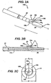
- the elongate member 12 of the tunnel notcher and guidewire delivery device 10 can have a variety of configurations, shapes, and sizes. As shown in FIG. 1 , however, the elongate member 12 has a generally hollow cylindrical shape and it includes proximal and distal ends 12a, 12b with an inner lumen 12c extending therebetween for slidably receiving a guidewire 16.
- the length 4 of the elongate member 12 can vary, but it should be sufficient to allow the proximal end 12a of the elongate member 12 to remain outside a patient's body while the distal end 12b is positioned within a bone tunnel, preferably between a bone plug or other anchoring member and a sidewall of the bone tunnel.
- FIG. 1 illustrates a generally elongate handle 14 that extends in a direction that is substantially transverse to a longitudinal axis L of the elongate member 12.
- Opposed gripping portions 14a, 14b can be formed on the handle 14 to conform to a user's fingers.
- a distal-facing surface 15 of each gripping portion 14a, 14b can be substantially concave for seating one or more fingers of the user. This allows the user to grasp the device 10 by positioning their fingers around the handle 14 so as to form a fist.
- handles or other devices can be used to facilitate grasping of the device 10.
- the distal end 12b of the elongate member 12 can also have a variety of configurations, but it should be adapted to be positioned between a bone tunnel and a bone plug or other anchoring member.
- the distal end 12b is also preferably configured such that at least a portion of it can be inserted into the bone tunnel to a particular depth to facilitate the correct positioning of the cutting element 18 with respect to the bone tunnel.
- the distal end 12b has a tapered tip 20 such that a diameter of the tip 20 decreases in a proximal to distal direction. This facilitates insertion of the distal end 12b between the sidewall of the bone tunnel and the anchoring member.
- the distal end 12b can also include markings 22 or other indicia disposed or formed thereon, as shown in FIGS. 1 and 2A , to indicate an insertion depth of the distal end 12b of the elongate member 12 into a bone tunnel.
- the markings 22, which are preferably located proximal to the cutting element 18, can optionally extend circumferentially around the elongate member 12 to facilitate visual access thereof.
- the markings 22 are radio-opaque to allow x-ray visualization thereof during an arthroscopic procedure.
- the device 10 also includes a cutting element 18 that is formed on a distal portion 13 of the elongate member 12.
- the cutting element 18, which is shown in more detail in FIGS. 2A-2C , can have any configuration and it can be disposed anywhere on the elongate member, but it should be effective to remove bone to form a notch adjacent to or within an opening of a bone tunnel.
- the cutting element 18 is positioned proximal to the distal end 12b of the elongate member 12, preferably just proximal to the tapered tip 20, to allow the tapered tip 20 to be disposed into a bone tunnel between a sidewall of the bone tunnel and a bone plug or other anchoring member disposed therein.
- the cutting element is also preferably disposed on one side of the elongate member 12, such that it is offset from the longitudinal axis L of the elongate member 12.
- the cutting element 18 can have a length l c ( FIG. 2C ) that is less than or equal to a diameter D of the elongate member 12. Such a configuration will allow the cutting element 18 to remove bone from the bone tunnel without coming into contact with and/or causing damage to the bone plug or other anchoring member disposed within the bone tunnel.
- the shape and size of the cutting element 18 can also vary, but in an exemplary embodiment it is substantially wedge-shaped such that it has a width w c that increases in a proximal to distal direction.
- a base portion 18b of the cutting element 18 is mated to or formed on the elongate member 12, and a cutting edge 18a is positioned a distance d apart from the elongate member 12.
- the distance d ( FIG. 2C ) between the cutting edge 18a and the elongate member 12 can vary, but it should be sufficient to allow a portion of bone adjacent to or within a bone tunnel to be removed such that a notch is created for receiving a bone screw.
- the cutting edge 18a is also preferably positioned at a location that is distal of the base portion 18b with respect to the longitudinal axis L of the elongate member 12. This can be achieved by providing a distal-facing surface 18c on the cutting element 18 that extends between the cutting edge 18a and the elongate member 12, and that is positioned at an acute angle ⁇ with respect to the longitudinal axis L of the elongate member 12. While the angle ⁇ can vary, in an exemplary embodiment, the angle ⁇ is in the range of about 20°to 70°.
- the distal-facing surface 18c can also optionally be substantially concave such that opposed edges 19a, 19b of the cutting element 18 form cutting edges that are effective to remove bone.
- the cutting edge 18a can have a substantially arcuate shape, such that the distance d between the cutting edge 18a and the elongate member 12 remains substantially constant along the entire length l c of the cutting edge 18a. Such curvature of the cutting edge 18a will facilitate removal of bone, and in particular it will allow a semi-circular notch to be formed in bone.
- the tunnel notcher and guidewire delivery device 10 includes an inner lumen 12c that extends through the elongate member 12 and the handle 14 for receiving a guidewire. Since the guidewire is preferably positioned within the inner lumen 12c during use of the device 10, the device 10 can optionally include a locking mechanism 24 formed thereon for maintaining a guidewire in a fixed position relative to the elongate member 12. While a variety of locking mechanisms known in the art can be used, FIGS. 1 and 3A-3B illustrate an exemplary embodiment of a locking mechanism 24 that is formed on the handle 14 of the elongate member 12. As shown, the locking mechanism 24 is in the form of a set screw 28 that is disposed within a threaded bore 26 formed in handle 14.
- the threaded bore 26 is in communication with the inner lumen 12c of the elongate member 12.
- the set screw 28 can be threaded into the threaded bore 26 to engage a guidewire 16 that is disposed within the inner lumen 12c of the elongate member 12, thereby locking the guidewire 16 in a fixed position.
- the tunnel notcher and guidewire delivery device 10 of the present invention can be used in a variety of medical procedures for preparing a bone tunnel for receiving a fastening element, such as a bone screw, to secure an anchoring member disposed within the bone tunnel.
- the device 10 is used to prepare a bone tunnel for anchoring a ligament therein, and in particular for arthroscopic femoral fixation of an anterior cruciate ligament (ACL) graft, as shown in FIGS. 4A-4E .
- ACL anterior cruciate ligament
- the graft ligament (not shown) is typically prepared by separating the graft into four tendon bundles, each of which is prepared by whip stitching a length of suture thereto. Two anchoring members, such as bone plugs, are then attached at each end of the ligament.
- FIGS. 4A-4E only show a bone tunnel 56 formed in the femoral bone 54, however, a person skilled in the art will appreciate that the device and methods of the present invention can be inserted through either or both of the femoral and tibial bones.
- FIGS. 4A-4E only show a bone plug 53 disposed within the femoral bone tunnel 56, and a graft ligament is not shown.
- a guidewire 16 is inserted through the device 10 of the present invention, preferably such that a portion of the guidewire 16 extends from the distal end 12b of the elongate member 12 to facilitate insertion of the distal tip 20 of the device 10 into the bone tunnel 56 between the bone plug 53 and a sidewall of the bone tunnel 56.
- the guidewire 16 is preferably locked in fixed position by rotating the set screw 28 of the locking mechanism 24. Since most guidewires are relatively flexible, it is preferable to only have a small portion of the guidewire 16 extend from the distal end 12b of the elongate member 12 to provide rigidity to the guidewire 16.
- the device 10 can then be inserted through the tibial bone tunnel 56 to position the tapered tip 20 of the elongate member 12 between the bone plug 53 and the femoral bone tunnel 56, as illustrated in FIGS. 4B and 4C .
- a mallet or other impacting tool can optionally be used to further impact the device 10 to advance it into the area between the bone plug 53 and the bone tunnel 56 to a desired depth.
- the radio-opaque markings 22 near the distal end 12b of the elongate member 12 can be used to indicate when the device 10 is at the correct depth.
- the device 10 is partially rotated about its longitudinal axis L such that cutting edge 18a of the cutting element 18 moves in a semi-circular direction, thereby removing a portion of bone to create a notch 58.
- the notch 58 is formed within or adjacent to an opening of the bone tunnel 56.
- the locking mechanism 24 is released by rotating the set screw 28 in the opposite direction, allowing the device 10 to be removed while leaving the guidewire 16 positioned within the bone tunnel 56, as illustrated by FIG. 4D , between the bone plug 53 and adjacent to the notch 58.
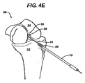
- a fastening element such as a bone screw 80, as shown in FIG. 4E
- a bone screw 80 can then be delivered by sliding the screw 80 along the guidewire 16 toward the notch 58.
- An insertion tool or driver mechanism 70 as shown, can optionally be used to advance the screw 80 along the guidewire 16, and to thread the screw 80 into the bone tunnel 56.
- the notch 58 will allow the threads of the bone screw 80 to engage the bone, and thus further rotation of the screw 80 will secure the bone plug 53 in the bone tunnel 56.
Description
- The present invention relates to apparatus and devices for repairing torn and/or damaged tissue, and in particular to apparatus and devices for creating a notch and positioning a guidewire within a bone tunnel.
- Ligaments are tough bands of tissue which serve to connect the articular extremities of bones, or to support or retain organs in place within the body. Ligaments are typically composed of coarse bundles of dense white fibrous tissue which are disposed in a parallel or closely interlaced manner, with the fibrous tissue being pliant and flexible, but not significantly extensible.
- In many cases, ligaments are torn or ruptured as a result of accidents or overexertion. Accordingly, various procedures have been developed to repair or replace such damaged ligaments. For example, in the human knee, the anterior and posterior cruciate ligaments (i.e., the ACL and PCL) extend between the top end of the tibia and the bottom end of the femur. The ACL and PCL cooperate, together with other ligaments and soft tissue, to provide both static and dynamic stability to the knee. Often, the ACL is ruptured or torn as a result of, for example, a sports-related injury. Consequently, various surgical procedures have been developed for reconstructing the ACL so as to restore normal function to the knee.
- In many instances, the ACL may be reconstructed by replacing the ruptured ACL with a graft ligament. More particularly, with such procedures, bone tunnels are typically formed in the top end of the tibia and the bottom end of the femur, and one end of the graft ligament is positioned in the femoral bone tunnel and the other end of the graft ligament is positioned in the tibial bone tunnel. The graft ligament thus extends between the femur and the tibia in substantially the same way, and with substantially the same function, as the original ACL, thereby allowing the graft ligament to cooperate with the surrounding anatomical structures so as to restore normal function to the knee.
- When anchoring a graft ligament to the tibia and the femur, the two ends of the graft ligament are typically attached to an anchoring member, such as a bone plug, that is inserted into a bone tunnel. Bone screws or similar fasteners are often used to maintain each bone plug within its respective tunnel. Such a procedure typically requires a recess to be formed in the bone adjacent to the bone tunnel to allow the bone screw to be inserted alongside the bone plug. The recess serves as a "starter hole" for the bone screw so that the screw can engage bone in a generally proper direction with respect to the bone tunnel. As the bone screw is threaded into the bone, the resulting interference fit between the bone plug and the bone screw secures the graft ligament in place in the bone tunnel.
- Since ACL repair is typically performed arthroscopically, the current procedure for forming a bone recess requires the surgeon to estimate the best location for positioning the bone screw adjacent to the bone plug. In particular, current devices for forming a recess in a bone tunnel have a relatively large size that requires that the recess be formed before the bone plug is inserted into the tunnel, thus the surgeon cannot determine the best location for the recess, and consequently for the bone screw, in relation to the bone plug. Once the recess is formed, a guidewire must be positioned between the anchoring member and a sidewall of the bone tunnel for delivering a bone screw to the tunnel at a location adjacent to the recess. Since the guidewire is delivered after formation of the notch, the position of the guidewire is often estimated as well. Accordingly, these methods and devices can result in misalignment of the bone screw, thus resulting in a high rate of divergence between the bone screw and the bone tunnel, and often in a loss of bone plug fixation within the bone tunnel. Unfortunately, screw/tunnel divergence is usually only identified postoperatively via radiographs, and the loss of bone plug fixation cannot be readily corrected, thereby resulting in an unsuccessful repair of a ruptured ACL.
- Thus, there remains a need for improved apparatus and devices for creating a notch and positioning a guidewire within a bone tunnel to provide an accurate, secure, and trouble-free fixation of a ligament within the bone tunnel. With these, improved methods are possible.
US 2002/173795 discusses an apparatus for removing bone from a femoral notch, or the like, which includes a guidewire and a router assembly. The router assembly comprises a cutting head fixed to a shaft rotatably disposed in a hole through a body portion of a shield assembly. A hood portion of the shield assembly extends from the body portion of the shield assembly and covers a first portion of the cutting head while leaving exposed a second portion of the cutting head. The guidewire extends through a hole in the shaft, a hole in the cutting head, and a hole in the shield assembly hood portion, such that the router assembly is movable along the guidewire. The shaft is rotatable in the shield assembly body portion such that the second portion of the cutting head is engageable with the bone and operative to remove portions of the bone. - The present invention provides apparatus for preparing a bone tunnel according to claim 1. The apparatus allows the positioning of a tunnel notcher and guidewire delivery device between a bone plug and a sidewall of a bone tunnel and manipulating the device such that a means for removing a portion of bone creates a notch in or adjacent to an opening of the bone tunnel. The tunnel notcher and guidewire delivery device can then be removed leaving a guidewire positioned between the bone plug and the bone tunnel adjacent to the notch. A bone screw can then be delivered along the guidewire to engage bone at the notch, and thereby secure the bone plug within the bone tunnel.
- Other advantageous features are set out in the dependent claims.
- The invention will be more fully understood from the following detailed description taken in conjunction with the accompanying drawings, in which:
-
FIG. 1 is a perspective view of one embodiment of a tunnel notcher and guidewire delivery device according to the present invention; -
FIG. 2A is an enlarged view of a cutting element on the tunnel notcher and guidewire delivery device shown inFIG. 1 ; -
FIG. 2B is a side, cross-sectional view of the cutting element shown inFIG. 2A taken along a longitudinal axis of the tunnel notcher and guidewire delivery device; -
FIG. 2C is an end view of the tunnel notcher and guidewire delivery device shown inFIG. 1 ; -
FIG. 3A is cross-sectional view of a locking mechanism on the tunnel notcher and guidewire delivery device shown inFIG. 1 ; -
FIG. 3B is a cross-sectional view of the locking mechanism shown inFIG. 3A in the locked position; -
FIG. 4A is an illustration of a human knee having a bone tunnel formed therein; -
FIG. 4B is an illustration of the human knee shown inFIG. 4A with a tunnel notcher and guidewire delivery device in accordance with the present invention being introduced into the bone tunnel; -
FIG. 4C is an illustration showing the tunnel notcher and guidewire delivery device ofFIG. 4B disposed within the bone tunnel to remove bone, forming a notch within the opening of the bone tunnel; -
FIG. 4D is an illustration showing the tunnel notcher and guidewire delivery device ofFIG. 4C removed from the bone tunnel, leaving a guide wire positioned within the bone tunnel adjacent to the notch; and -
FIG. 4E is an illustration showing a bone screw being delivered along the guide wire shown inFIG. 4D to the bone tunnel in accordance with another embodiment of the present invention. - The present invention provides a device for creating a notch in a bone tunnel, and for positioning a guidewire within the bone tunnel. In general, as shown in
FIG. 1 , thedevice 10 includes anelongate member 12 having aninner lumen 12c extending therethrough and adapted to receive aguidewire 16. A cuttingelement 18 is formed on or adjacent to adistal portion 13 of theelongate member 12, and it is effective to remove bone within or adjacent to an opening of a bone tunnel. Thedevice 10 can also include ahandle 14 mated to or formed on aproximal end 12a of theelongate member 12 for grasping thedevice 10. In use, thedevice 10 can be at least partially positioned within a bone tunnel containing a bone plug, and it can be manipulated to form a notch within or adjacent to an opening of the bone tunnel using the cuttingelement 18. Thedevice 10 is also effective to deliver aguidewire 16 to the bone tunnel at a location adjacent to the notch. Theguidewire 16 can subsequently be used to deliver a fastening element, such as a bone screw, to the notch, thus allowing the bone screw to be threaded into the bone tunnel to secure the bone plug or other anchoring member within the tunnel. - The apparatus and devices of the present invention are particularly advantageous in that they allow a surgeon to remove bone to form a notch within or adjacent to an opening of a bone tunnel after a bone plug or other anchoring member has been positioned in the bone tunnel, thereby ensuring proper positioning of the notch and subsequently of a fastening element with respect to the bone plug. The
device 10 also eliminates the additional step of positioning a guidewire after the notch is formed since the guidewire is implanted using the tunnel notcher and guidewire delivery device, thus further providing proper alignment of the bone screw with the notch and the bone plug or other anchoring member disposed within the bone tunnel. - Still referring to
FIG. 1 , theelongate member 12 of the tunnel notcher andguidewire delivery device 10 can have a variety of configurations, shapes, and sizes. As shown inFIG. 1 , however, theelongate member 12 has a generally hollow cylindrical shape and it includes proximal anddistal ends inner lumen 12c extending therebetween for slidably receiving aguidewire 16. The length 4 of theelongate member 12 can vary, but it should be sufficient to allow theproximal end 12a of theelongate member 12 to remain outside a patient's body while thedistal end 12b is positioned within a bone tunnel, preferably between a bone plug or other anchoring member and a sidewall of the bone tunnel. - The
proximal end 12a of theelongate member 12 preferably has ahandle 14 mated thereto or formed thereon to facilitate grasping thedevice 10. While thehandle 14 can have any shape and size,FIG. 1 illustrates a generallyelongate handle 14 that extends in a direction that is substantially transverse to a longitudinal axis L of theelongate member 12. Opposedgripping portions handle 14 to conform to a user's fingers. In particular, a distal-facingsurface 15 of eachgripping portion device 10 by positioning their fingers around thehandle 14 so as to form a fist. A person skilled in the art will appreciate that a variety of handles or other devices can be used to facilitate grasping of thedevice 10. - The
distal end 12b of theelongate member 12 can also have a variety of configurations, but it should be adapted to be positioned between a bone tunnel and a bone plug or other anchoring member. Thedistal end 12b is also preferably configured such that at least a portion of it can be inserted into the bone tunnel to a particular depth to facilitate the correct positioning of the cuttingelement 18 with respect to the bone tunnel. In an exemplary embodiment, shown inFIGS. 2A and 2B , thedistal end 12b has a taperedtip 20 such that a diameter of thetip 20 decreases in a proximal to distal direction. This facilitates insertion of thedistal end 12b between the sidewall of the bone tunnel and the anchoring member. Thedistal end 12b can also includemarkings 22 or other indicia disposed or formed thereon, as shown inFIGS. 1 and2A , to indicate an insertion depth of thedistal end 12b of theelongate member 12 into a bone tunnel. Themarkings 22, which are preferably located proximal to the cuttingelement 18, can optionally extend circumferentially around theelongate member 12 to facilitate visual access thereof. In an exemplary embodiment, themarkings 22 are radio-opaque to allow x-ray visualization thereof during an arthroscopic procedure. - As previously stated, the
device 10 also includes a cuttingelement 18 that is formed on adistal portion 13 of theelongate member 12. The cuttingelement 18, which is shown in more detail inFIGS. 2A-2C , can have any configuration and it can be disposed anywhere on the elongate member, but it should be effective to remove bone to form a notch adjacent to or within an opening of a bone tunnel. In an exemplary embodiment, as shown, the cuttingelement 18 is positioned proximal to thedistal end 12b of theelongate member 12, preferably just proximal to the taperedtip 20, to allow the taperedtip 20 to be disposed into a bone tunnel between a sidewall of the bone tunnel and a bone plug or other anchoring member disposed therein. The cutting element is also preferably disposed on one side of theelongate member 12, such that it is offset from the longitudinal axis L of theelongate member 12. In particular, the cuttingelement 18 can have a length lc (FIG. 2C ) that is less than or equal to a diameter D of theelongate member 12. Such a configuration will allow the cuttingelement 18 to remove bone from the bone tunnel without coming into contact with and/or causing damage to the bone plug or other anchoring member disposed within the bone tunnel. - The shape and size of the cutting
element 18 can also vary, but in an exemplary embodiment it is substantially wedge-shaped such that it has a width wc that increases in a proximal to distal direction. Abase portion 18b of the cuttingelement 18 is mated to or formed on theelongate member 12, and acutting edge 18a is positioned a distance d apart from theelongate member 12. The distance d (FIG. 2C ) between thecutting edge 18a and theelongate member 12 can vary, but it should be sufficient to allow a portion of bone adjacent to or within a bone tunnel to be removed such that a notch is created for receiving a bone screw. Thecutting edge 18a is also preferably positioned at a location that is distal of thebase portion 18b with respect to the longitudinal axis L of theelongate member 12. This can be achieved by providing a distal-facingsurface 18c on the cuttingelement 18 that extends between thecutting edge 18a and theelongate member 12, and that is positioned at an acute angle α with respect to the longitudinal axis L of theelongate member 12. While the angle α can vary, in an exemplary embodiment, the angle α is in the range of about 20°to 70°. The distal-facingsurface 18c can also optionally be substantially concave such that opposededges 19a, 19b of the cuttingelement 18 form cutting edges that are effective to remove bone. - In another embodiment, the
cutting edge 18a can have a substantially arcuate shape, such that the distance d between thecutting edge 18a and theelongate member 12 remains substantially constant along the entire length lc of thecutting edge 18a. Such curvature of thecutting edge 18a will facilitate removal of bone, and in particular it will allow a semi-circular notch to be formed in bone. - As previously stated, the tunnel notcher and
guidewire delivery device 10 includes aninner lumen 12c that extends through theelongate member 12 and thehandle 14 for receiving a guidewire. Since the guidewire is preferably positioned within theinner lumen 12c during use of thedevice 10, thedevice 10 can optionally include alocking mechanism 24 formed thereon for maintaining a guidewire in a fixed position relative to theelongate member 12. While a variety of locking mechanisms known in the art can be used,FIGS. 1 and3A-3B illustrate an exemplary embodiment of alocking mechanism 24 that is formed on thehandle 14 of theelongate member 12. As shown, thelocking mechanism 24 is in the form of aset screw 28 that is disposed within a threadedbore 26 formed inhandle 14. The threaded bore 26 is in communication with theinner lumen 12c of theelongate member 12. In use, as shown inFIG. 3B , theset screw 28 can be threaded into the threaded bore 26 to engage aguidewire 16 that is disposed within theinner lumen 12c of theelongate member 12, thereby locking theguidewire 16 in a fixed position. - The tunnel notcher and
guidewire delivery device 10 of the present invention can be used in a variety of medical procedures for preparing a bone tunnel for receiving a fastening element, such as a bone screw, to secure an anchoring member disposed within the bone tunnel. In an exemplary embodiment, however, thedevice 10 is used to prepare a bone tunnel for anchoring a ligament therein, and in particular for arthroscopic femoral fixation of an anterior cruciate ligament (ACL) graft, as shown inFIGS. 4A-4E . While various graft ligaments can be used, the graft ligament (not shown) is typically prepared by separating the graft into four tendon bundles, each of which is prepared by whip stitching a length of suture thereto. Two anchoring members, such as bone plugs, are then attached at each end of the ligament. - An incision is then made, following medically acceptable patient preparation and anesthetization, near the end of the
tibial bone 52 below the patella, and abone tunnel 56 is formed through the tibial andfemoral bones FIGS. 4A-4E only show abone tunnel 56 formed in thefemoral bone 54, however, a person skilled in the art will appreciate that the device and methods of the present invention can be inserted through either or both of the femoral and tibial bones. One end of the graft ligament, i.e., the leading end, is then passed through the tibial tunnel into thefemoral tunnel 56, and the other end of the graft ligament, i.e., the trailing end, remains outside of the tibial bone tunnel, thus permitting access through the tibial tunnel to thefemoral tunnel 56. Again, for illustration purposes,FIGS. 4A-4E only show abone plug 53 disposed within thefemoral bone tunnel 56, and a graft ligament is not shown. - In preparation for use, a
guidewire 16 is inserted through thedevice 10 of the present invention, preferably such that a portion of theguidewire 16 extends from thedistal end 12b of theelongate member 12 to facilitate insertion of thedistal tip 20 of thedevice 10 into thebone tunnel 56 between thebone plug 53 and a sidewall of thebone tunnel 56. Theguidewire 16 is preferably locked in fixed position by rotating theset screw 28 of thelocking mechanism 24. Since most guidewires are relatively flexible, it is preferable to only have a small portion of theguidewire 16 extend from thedistal end 12b of theelongate member 12 to provide rigidity to theguidewire 16. - The
device 10 can then be inserted through thetibial bone tunnel 56 to position the taperedtip 20 of theelongate member 12 between thebone plug 53 and thefemoral bone tunnel 56, as illustrated inFIGS. 4B and4C . A mallet or other impacting tool can optionally be used to further impact thedevice 10 to advance it into the area between thebone plug 53 and thebone tunnel 56 to a desired depth. The radio-opaque markings 22 near thedistal end 12b of theelongate member 12 can be used to indicate when thedevice 10 is at the correct depth. - Once properly positioned, the
device 10 is partially rotated about its longitudinal axis L such thatcutting edge 18a of the cuttingelement 18 moves in a semi-circular direction, thereby removing a portion of bone to create anotch 58. As shown inFIG. 4D , thenotch 58 is formed within or adjacent to an opening of thebone tunnel 56. After creating thenotch 58, thelocking mechanism 24 is released by rotating theset screw 28 in the opposite direction, allowing thedevice 10 to be removed while leaving theguidewire 16 positioned within thebone tunnel 56, as illustrated byFIG. 4D , between thebone plug 53 and adjacent to thenotch 58. - A fastening element, such as a
bone screw 80, as shown inFIG. 4E , can then be delivered by sliding thescrew 80 along theguidewire 16 toward thenotch 58. An insertion tool ordriver mechanism 70, as shown, can optionally be used to advance thescrew 80 along theguidewire 16, and to thread thescrew 80 into thebone tunnel 56. When thebone screw 80 is positioned adjacent to thebone tunnel 56, thenotch 58 will allow the threads of thebone screw 80 to engage the bone, and thus further rotation of thescrew 80 will secure thebone plug 53 in thebone tunnel 56. - One skilled in the art will appreciate further features and advantages of the invention based on the above-described embodiments. Accordingly, the invention is not to be limited by what has been particularly shown and described, except as indicated by the appended claims.
Claims (16)
- Apparatus for preparing a bone tunnel, comprising:a bone plug (53) for inserting into a bone tunnel (56);a tunnel notcher and guidewire delivery device (10) for positioning between the bone plug (53) and a sidewall of the bone tunnel (56), comprising:an elongate member (12) having an inner lumen (12c) extending therethrough and adapted to receive a guidewire for implanting the guidewire; anda cutting element (18) disposed on the elongate member for removing a portion of bone to create a notch (58) in an opening of a bone tunnel (56), the notch (58) being effective to facilitate placement of a bone screw (80) within the bone tunnel (56) for securing the bone plug (53) therein; andmeans for removing the tunnel notcher and guidewire delivery device (10) such that a guidewire (16) remains positioned between the bone plug (53) and the bone tunnel (56) adjacent to the notch,characterised in that the cutting element (18) includes a cutting edge (18a) that is positioned a distance (d) apart from the elongate member (12), and that has a length (lc) that is less than a diameter (D) of the elongate member.
- The apparatus claim 1, wherein the notch (58) has a substantially semi-circular shape.
- The apparatus of claim 1 or claim 2, further comprising a bone screw (80) for delivering along the guidewire (16) to engage bone at the notch (58), and to secure the bone plug (53) within the bone tunnel (56).
- The apparatus of any one of claims 1 to 3, wherein the guidewire (16) is disposed within the tunnel notcher and guidewire delivery device (10) during positioning of the tunnel notcher and guidewire delivery device (10) between the bone plug (53) and the bone tunnel (56).
- The apparatus of claim 4, wherein the guidewire (16) is in a releasably fixed position with respect to the tunnel notcher and guidewire delivery device (10) during positioning of the tunnel notcher and guidewire delivery device (10) between the bone plug (53) and the bone tunnel (56).
- The apparatus of claim 5, further comprising a locking mechanism (24) formed on the tunnel notcher and guidewire delivery device and adapted to releasably fix the guidewire with respect to the tunnel notcher and guidewire delivery device.
- The apparatus of claim 6, wherein the locking mechanism is coupled to a handle (14) formed on the elongate member.
- The apparatus of claim 7, wherein the locking mechanism comprises a threaded member (28) disposed within a threaded bore (26) formed in the handle, the threaded bore being in communication with the inner lumen of the elongate member containing the guidewire.
- The apparatus of any one of the preceding claims, wherein a distal portion (20) of the elongate member is substantially tapered to allow the distal portion to be positioned between the bone plug and the sidewall of the bone tunnel.
- The apparatus of claim 1, wherein the cutting element extends distally outward from the elongate member.
- The apparatus of claim 10, wherein the cutting element is substantially wedge-shaped and includes a distal-facing surface (18c) that is disposed at an acute angle with respect to a longitudinal axis (L) of the elongate member.
- The apparatus of claim 11, wherein the angle is less than 90°.
- The apparatus of any one of the preceding claim, further comprising a plurality of indicia formed on a distal portion of the elongate member and adapted to indicate a depth of the elongate member within a bone tunnel.
- The device of claim 12, wherein the angle is in the range of about 20° to 70°.
- The device of any one of claims 1 to 14, wherein the cutting element includes a base portion coupled to the elongate member.
- The device of claim 15, wherein the cutting edge is positioned distal to the base portion.
Priority Applications (2)
| Application Number | Priority Date | Filing Date | Title |
|---|---|---|---|
| EP10178701A EP2286744B8 (en) | 2004-03-05 | 2005-03-04 | Tunnel notcher and guidewire delivery device |
| EP10178678A EP2292162B1 (en) | 2004-03-05 | 2005-03-04 | Tunnel notcher and guidewire delivery device |
Applications Claiming Priority (2)
| Application Number | Priority Date | Filing Date | Title |
|---|---|---|---|
| US10/708,467 US8070750B2 (en) | 2004-03-05 | 2004-03-05 | Tunnel notcher and guidewire delivery device |
| EP05251329A EP1570793B1 (en) | 2004-03-05 | 2005-03-04 | Tunnel notcher and guidewire delivery device |
Related Parent Applications (1)
| Application Number | Title | Priority Date | Filing Date |
|---|---|---|---|
| EP05251329A Division EP1570793B1 (en) | 2004-03-05 | 2005-03-04 | Tunnel notcher and guidewire delivery device |
Related Child Applications (2)
| Application Number | Title | Priority Date | Filing Date |
|---|---|---|---|
| EP10178701A Division-Into EP2286744B8 (en) | 2004-03-05 | 2005-03-04 | Tunnel notcher and guidewire delivery device |
| EP10178678A Division-Into EP2292162B1 (en) | 2004-03-05 | 2005-03-04 | Tunnel notcher and guidewire delivery device |
Publications (2)
| Publication Number | Publication Date |
|---|---|
| EP1941841A1 EP1941841A1 (en) | 2008-07-09 |
| EP1941841B1 true EP1941841B1 (en) | 2012-08-29 |
Family
ID=34749176
Family Applications (4)
| Application Number | Title | Priority Date | Filing Date |
|---|---|---|---|
| EP08075207A Expired - Fee Related EP1941841B1 (en) | 2004-03-05 | 2005-03-04 | Tunnel notcher and guidewire delivery device |
| EP05251329A Expired - Fee Related EP1570793B1 (en) | 2004-03-05 | 2005-03-04 | Tunnel notcher and guidewire delivery device |
| EP10178678A Expired - Fee Related EP2292162B1 (en) | 2004-03-05 | 2005-03-04 | Tunnel notcher and guidewire delivery device |
| EP10178701A Expired - Fee Related EP2286744B8 (en) | 2004-03-05 | 2005-03-04 | Tunnel notcher and guidewire delivery device |
Family Applications After (3)
| Application Number | Title | Priority Date | Filing Date |
|---|---|---|---|
| EP05251329A Expired - Fee Related EP1570793B1 (en) | 2004-03-05 | 2005-03-04 | Tunnel notcher and guidewire delivery device |
| EP10178678A Expired - Fee Related EP2292162B1 (en) | 2004-03-05 | 2005-03-04 | Tunnel notcher and guidewire delivery device |
| EP10178701A Expired - Fee Related EP2286744B8 (en) | 2004-03-05 | 2005-03-04 | Tunnel notcher and guidewire delivery device |
Country Status (6)
| Country | Link |
|---|---|
| US (2) | US8070750B2 (en) |
| EP (4) | EP1941841B1 (en) |
| JP (1) | JP4762575B2 (en) |
| AU (1) | AU2005200673B2 (en) |
| CA (2) | CA2637682C (en) |
| DE (1) | DE602005007078D1 (en) |
Families Citing this family (65)
| Publication number | Priority date | Publication date | Assignee | Title |
|---|---|---|---|---|
| US8070750B2 (en) | 2004-03-05 | 2011-12-06 | Depuy Mitek, Inc. | Tunnel notcher and guidewire delivery device |
| US7763074B2 (en) | 2004-10-20 | 2010-07-27 | The Board Of Trustees Of The Leland Stanford Junior University | Systems and methods for posterior dynamic stabilization of the spine |
| US9161783B2 (en) | 2004-10-20 | 2015-10-20 | Vertiflex, Inc. | Interspinous spacer |
| US8317864B2 (en) | 2004-10-20 | 2012-11-27 | The Board Of Trustees Of The Leland Stanford Junior University | Systems and methods for posterior dynamic stabilization of the spine |
| US8167944B2 (en) | 2004-10-20 | 2012-05-01 | The Board Of Trustees Of The Leland Stanford Junior University | Systems and methods for posterior dynamic stabilization of the spine |
| US9023084B2 (en) | 2004-10-20 | 2015-05-05 | The Board Of Trustees Of The Leland Stanford Junior University | Systems and methods for stabilizing the motion or adjusting the position of the spine |
| US8409282B2 (en) | 2004-10-20 | 2013-04-02 | Vertiflex, Inc. | Systems and methods for posterior dynamic stabilization of the spine |
| US9119680B2 (en) | 2004-10-20 | 2015-09-01 | Vertiflex, Inc. | Interspinous spacer |
| WO2009009049A2 (en) | 2004-10-20 | 2009-01-15 | Vertiflex, Inc. | Interspinous spacer |
| US8152837B2 (en) | 2004-10-20 | 2012-04-10 | The Board Of Trustees Of The Leland Stanford Junior University | Systems and methods for posterior dynamic stabilization of the spine |
| US8128662B2 (en) | 2004-10-20 | 2012-03-06 | Vertiflex, Inc. | Minimally invasive tooling for delivery of interspinous spacer |
| EP2219538B1 (en) | 2004-12-06 | 2022-07-06 | Vertiflex, Inc. | Spacer insertion instrument |
| DE102006037602A1 (en) * | 2006-08-10 | 2008-02-21 | Cas Innovations Ag | Auxiliary device for producing a mechanical connection between a medical implant and a tissue part of a patient |
| US8845726B2 (en) | 2006-10-18 | 2014-09-30 | Vertiflex, Inc. | Dilator |
| WO2008092029A2 (en) | 2007-01-24 | 2008-07-31 | Access Scientific, Inc. | Access device |
| CA2684461C (en) | 2007-04-16 | 2015-06-30 | Vertiflex Inc. | Interspinous spacer |
| US8105286B2 (en) | 2007-04-18 | 2012-01-31 | Access Scientific, Inc. | Access device |
| JP2010524586A (en) * | 2007-04-18 | 2010-07-22 | アクセス サイエンティフィック、インク. | Approach device |
| US8740956B2 (en) | 2008-01-10 | 2014-06-03 | J. Scott Smith | Pedicle screw |
| US8986318B2 (en) | 2008-06-03 | 2015-03-24 | Jeffrey Scott Smith | Pedicle depth measuring apparatus |
| US9668775B2 (en) | 2008-06-03 | 2017-06-06 | Jeffrey Scott Smith | Pedicle screw |
| AU2009206098B2 (en) | 2008-01-15 | 2014-10-30 | Vertiflex, Inc. | Interspinous spacer |
| US8343161B2 (en) * | 2008-02-21 | 2013-01-01 | Covidien Lp | Femoral guide for ACL repair having multiple lumen |
| US8430884B2 (en) | 2008-02-21 | 2013-04-30 | Covidien Lp | Femoral guide for ACL repair having selectively deployable femoral surface engagement member |
| US20090216243A1 (en) * | 2008-02-21 | 2009-08-27 | Paul Re | Guide for creating femoral tunnel during acl reconstruction |
| US8282647B2 (en) * | 2008-02-21 | 2012-10-09 | Tyco Healthcare Group Lp | Femoral guide for ACL repair having adjustable offset |
| US8430883B2 (en) * | 2008-02-21 | 2013-04-30 | Covidien Lp | Femoral guide for ACL repair having reduced profile for left/right knee configurations |
| US8734461B2 (en) * | 2008-03-04 | 2014-05-27 | Smith & Nephew, Inc. | Device and method for use during ligament reconstruction surgery |
| RU2555131C2 (en) | 2008-12-02 | 2015-07-10 | Смит Энд Нефью, Инк. | Prosthesis for implantation into iliac canal |
| CA2812775C (en) | 2009-08-20 | 2015-09-29 | Howmedica Osteonics Corp. | Flexible acl instrumentation, kit and method |
| AU2011213558A1 (en) | 2010-02-08 | 2012-09-27 | Access Scientific, Inc. | Access device |
| EP2547279A1 (en) | 2010-03-18 | 2013-01-23 | Smith&Nephew, Inc. | A device for use during ligament reconstruction surgery |
| ES2399785B1 (en) * | 2010-08-06 | 2014-02-25 | Tomas Ramos Marin | USEFUL FOR OBTAINING BONE TUNNELS. |
| US8911445B2 (en) * | 2011-01-28 | 2014-12-16 | DePuy Sysnthes Products, LLC | Reamer guide systems and methods of use |
| KR101805380B1 (en) * | 2011-01-28 | 2017-12-06 | 신세스 게엠바하 | Reamer guide systems |
| US9795398B2 (en) | 2011-04-13 | 2017-10-24 | Howmedica Osteonics Corp. | Flexible ACL instrumentation, kit and method |
| US8932295B1 (en) | 2011-06-01 | 2015-01-13 | Surgical Device Exchange, LLC | Bone graft delivery system and method for using same |
| US20130066149A1 (en) * | 2011-09-12 | 2013-03-14 | A.M. Surgical, Inc. | Endoscopic hook blade and use thereof |
| US9381021B2 (en) * | 2011-09-23 | 2016-07-05 | Biomet Sports Medicine, Llc | Method and apparatus for forming a hole in bone during a surgical procedure |
| US9445803B2 (en) | 2011-11-23 | 2016-09-20 | Howmedica Osteonics Corp. | Filamentary suture anchor |
| US9808242B2 (en) | 2012-04-06 | 2017-11-07 | Howmedica Osteonics Corp. | Knotless filament anchor for soft tissue repair |
| US20130289399A1 (en) * | 2012-04-27 | 2013-10-31 | Vertiflex, Inc. | Decompression systems and methods of using the same |
| US8821494B2 (en) | 2012-08-03 | 2014-09-02 | Howmedica Osteonics Corp. | Surgical instruments and methods of use |
| US9078740B2 (en) | 2013-01-21 | 2015-07-14 | Howmedica Osteonics Corp. | Instrumentation and method for positioning and securing a graft |
| US9402620B2 (en) | 2013-03-04 | 2016-08-02 | Howmedica Osteonics Corp. | Knotless filamentary fixation devices, assemblies and systems and methods of assembly and use |
| US9326777B2 (en) * | 2013-03-14 | 2016-05-03 | Amendia, Inc. | Decorticating surgical instruments and guidance systems with tactile feedback |
| US9566087B2 (en) | 2013-03-15 | 2017-02-14 | Access Scientific, Llc | Vascular access device |
| US8945137B1 (en) | 2013-03-15 | 2015-02-03 | Surgical Device Exchange, LLC | Bone graft delivery system and method for using same |
| US9668881B1 (en) | 2013-03-15 | 2017-06-06 | Surgentec, Llc | Bone graft delivery system and method for using same |
| US9675303B2 (en) | 2013-03-15 | 2017-06-13 | Vertiflex, Inc. | Visualization systems, instruments and methods of using the same in spinal decompression procedures |
| WO2014176270A1 (en) | 2013-04-22 | 2014-10-30 | Pivot Medical, Inc. | Method and apparatus for attaching tissue to bone |
| EP3139848A4 (en) | 2014-05-07 | 2018-06-13 | Vertiflex, Inc. | Spinal nerve decompression systems, dilation systems, and methods of using the same |
| US10045803B2 (en) | 2014-07-03 | 2018-08-14 | Mayo Foundation For Medical Education And Research | Sacroiliac joint fusion screw and method |
| US9883898B2 (en) | 2014-08-07 | 2018-02-06 | Jeffrey Scott Smith | Pedicle screw with electro-conductive coating or portion |
| US9986992B2 (en) | 2014-10-28 | 2018-06-05 | Stryker Corporation | Suture anchor and associated methods of use |
| US10080583B2 (en) | 2014-12-12 | 2018-09-25 | Depuy Mitel, Llc | Dilator for accessing a joint space |
| US10238507B2 (en) | 2015-01-12 | 2019-03-26 | Surgentec, Llc | Bone graft delivery system and method for using same |
| US11027099B2 (en) | 2015-04-30 | 2021-06-08 | Smiths Medical Asd, Inc. | Vascular access device |
| US10413332B2 (en) | 2016-04-25 | 2019-09-17 | Imds Llc | Joint fusion implant and methods |
| US9833321B2 (en) | 2016-04-25 | 2017-12-05 | Imds Llc | Joint fusion instrumentation and methods |
| GB2565598A (en) * | 2017-08-18 | 2019-02-20 | Hoogland Spine Products Gmbh | Surgical reamer for removing bone |
| US10569059B2 (en) | 2018-03-01 | 2020-02-25 | Asspv, Llc | Guidewire retention device |
| US10687828B2 (en) | 2018-04-13 | 2020-06-23 | Surgentec, Llc | Bone graft delivery system and method for using same |
| US11116647B2 (en) | 2018-04-13 | 2021-09-14 | Surgentec, Llc | Bone graft delivery system and method for using same |
| US11510686B2 (en) | 2018-07-05 | 2022-11-29 | Conmed Corporation | Retrograde drilling device |
Family Cites Families (55)
| Publication number | Priority date | Publication date | Assignee | Title |
|---|---|---|---|---|
| US571400A (en) * | 1896-11-17 | Mortising-chisel | ||
| US1166723A (en) * | 1915-01-14 | 1916-01-04 | Wiley Stark | Attachment for pneumatic machine-riveters. |
| US1280785A (en) * | 1918-05-31 | 1918-10-08 | George Mcconnell | Woodworking-tool. |
| US1289722A (en) * | 1918-10-03 | 1918-12-31 | Charles Fournier | Ship-reaming tool. |
| US1418125A (en) * | 1921-08-26 | 1922-05-30 | William P Carroll | Metal-working tool |
| US1471062A (en) * | 1923-03-24 | 1923-10-16 | Victor T Riblett | Flue tool |
| US1598458A (en) * | 1924-12-12 | 1926-08-31 | John P Sullivan | Tool for removing boiler tubes |
| US1781863A (en) * | 1928-03-22 | 1930-11-18 | Shoemaker William Walter | Cutting tool |
| US1875612A (en) * | 1930-06-09 | 1932-09-06 | Henry Beinert | Wrecking implement |
| US2009795A (en) * | 1934-01-23 | 1935-07-30 | Joyce K Graham | Chipping and cutting tool |
| US2250434A (en) * | 1937-02-25 | 1941-07-22 | Dugaw Eugene | Combination nail set and patch hole making tool |
| US2465305A (en) * | 1944-12-09 | 1949-03-22 | A P Parts Corp | Cutting instrument |
| US3043002A (en) * | 1959-10-05 | 1962-07-10 | Lowell N Brown | Method and tools for repairing muffler assemblies |
| US3088454A (en) * | 1960-01-06 | 1963-05-07 | Wallace B Shute | Surgical instrument |
| US3554192A (en) * | 1967-07-24 | 1971-01-12 | Orthopedic Equipment Co | Medullary space drill |
| US3698085A (en) * | 1970-12-24 | 1972-10-17 | Jimmy C Ray | Sleeve slitter |
| US4603694A (en) * | 1983-03-08 | 1986-08-05 | Richards Medical Company | Arthroscopic shaver |
| US4573448A (en) * | 1983-10-05 | 1986-03-04 | Pilling Co. | Method for decompressing herniated intervertebral discs |
| DE8406730U1 (en) * | 1984-03-05 | 1984-04-26 | Waldemar Link (Gmbh & Co), 2000 Hamburg | Surgical chisel |
| US5122146A (en) * | 1988-02-04 | 1992-06-16 | Pfizer Hospital Products Group, Inc. | Apparatus for reducing a fracture |
| US4881537A (en) * | 1988-08-10 | 1989-11-21 | Charles Henning | Surgical instrument, and methods for forming a channel in a femoral condyle including reconstructing an anterior cruciate ligament |
| JPH0818331B2 (en) | 1989-07-17 | 1996-02-28 | トーヨーエイテック株式会社 | Slicing equipment |
| US4978349A (en) * | 1989-08-03 | 1990-12-18 | Synthes (U.S.A.) | Fixation plate |
| US5139520A (en) * | 1990-01-31 | 1992-08-18 | American Cyanamid Company | Method for acl reconstruction |
| US5190548A (en) | 1991-04-10 | 1993-03-02 | Linvatec Corporation | Surgical reamer |
| US5520693A (en) * | 1992-02-19 | 1996-05-28 | Mcguire; David A. | Femoral guide and methods of precisely forming bone tunnels in cruciate ligament reconstruction of the knee |
| US5908423A (en) * | 1993-05-27 | 1999-06-01 | Howmedica, Inc. | Flexible medullary reaming system |
| US5437675A (en) * | 1993-06-11 | 1995-08-01 | Wilson; Franklin D. | Polygonal bone punch |
| CA2131141A1 (en) * | 1993-09-24 | 1995-03-25 | James A. Boucher | Ligament graft protection apparatus and method |
| SE9304261D0 (en) * | 1993-12-22 | 1993-12-22 | Radi Medical Systems | Biopsy sampling device |
| US5643273A (en) * | 1995-02-17 | 1997-07-01 | Clark; Ron | ACL bone tunnel projection drill guide and method for its use |
| US5807276A (en) * | 1995-03-09 | 1998-09-15 | Russin; Lincoln David | Biopsy device and method |
| US5632747A (en) * | 1995-03-15 | 1997-05-27 | Osteotech, Inc. | Bone dowel cutter |
| AUPN238795A0 (en) * | 1995-04-12 | 1995-05-11 | Hip Developments International Pty Ltd | Improved process for knee reconstruction |
| US5645545A (en) * | 1995-08-14 | 1997-07-08 | Zimmer, Inc. | Self reaming intramedullary nail and method for using the same |
| JPH09149907A (en) * | 1995-11-29 | 1997-06-10 | Terumo Corp | Bone fixing tool, and bone fixing system |
| US5817095A (en) * | 1996-02-22 | 1998-10-06 | Smith & Nephew, Inc. | Undercutting surgical instrument |
| US5755718A (en) * | 1996-06-04 | 1998-05-26 | Sklar; Joseph H. | Apparatus and method for reconstructing ligaments |
| US5741256A (en) * | 1997-01-13 | 1998-04-21 | Synthes (U.S.A.) | Helical osteosynthetic implant |
| US6395011B1 (en) * | 1998-07-17 | 2002-05-28 | Johnson & Johnson | Method and apparatus for harvesting and implanting bone plugs |
| US6110175A (en) * | 1999-01-20 | 2000-08-29 | Synthes (Usa) | Surgical chisel and method of using same |
| US6770079B2 (en) * | 1999-03-16 | 2004-08-03 | American Osteomedix, Inc. | Apparatus and method for fixation of osteoporotic bone |
| US6764491B2 (en) * | 1999-10-21 | 2004-07-20 | Sdgi Holdings, Inc. | Devices and techniques for a posterior lateral disc space approach |
| US6540752B1 (en) * | 1999-11-01 | 2003-04-01 | Greg Hicken | Threaded bone tunnel dilator |
| US6270501B1 (en) * | 1999-11-08 | 2001-08-07 | The Regents Of The University Of Michigan | Surgical method and apparatus and cannulated scalpel for use therein |
| CA2723071C (en) * | 2000-02-03 | 2012-05-01 | Baylor College Of Medicine | Methods and devices for intraosseous nerve ablation |
| US6409730B1 (en) * | 2000-05-31 | 2002-06-25 | Synthes (Usa) | Humeral spiral blade |
| US6679886B2 (en) * | 2000-09-01 | 2004-01-20 | Synthes (Usa) | Tools and methods for creating cavities in bone |
| US6840941B2 (en) * | 2001-10-31 | 2005-01-11 | Depuy Acromed, Inc. | Vertebral endplate chisel |
| FI113616B (en) * | 2002-04-22 | 2004-05-31 | Inion Ltd | Instrument |
| DE20300988U1 (en) * | 2003-01-23 | 2003-04-03 | Stryker Trauma Gmbh | Drilling tool for bone, especially the proximal femur |
| US20050159676A1 (en) * | 2003-08-13 | 2005-07-21 | Taylor James D. | Targeted biopsy delivery system |
| US8070750B2 (en) | 2004-03-05 | 2011-12-06 | Depuy Mitek, Inc. | Tunnel notcher and guidewire delivery device |
| US20070106174A1 (en) * | 2005-10-07 | 2007-05-10 | Femspec Llc | Intrauterine anesthetic applicator and cell collection device and method of use |
| US7473232B2 (en) * | 2006-02-24 | 2009-01-06 | Boston Scientific Scimed, Inc. | Obtaining a tissue sample |
-
2004
- 2004-03-05 US US10/708,467 patent/US8070750B2/en active Active
-
2005
- 2005-02-15 AU AU2005200673A patent/AU2005200673B2/en not_active Ceased
- 2005-03-04 EP EP08075207A patent/EP1941841B1/en not_active Expired - Fee Related
- 2005-03-04 EP EP05251329A patent/EP1570793B1/en not_active Expired - Fee Related
- 2005-03-04 DE DE602005007078T patent/DE602005007078D1/en active Active
- 2005-03-04 CA CA2637682A patent/CA2637682C/en not_active Expired - Fee Related
- 2005-03-04 EP EP10178678A patent/EP2292162B1/en not_active Expired - Fee Related
- 2005-03-04 JP JP2005061260A patent/JP4762575B2/en not_active Expired - Fee Related
- 2005-03-04 EP EP10178701A patent/EP2286744B8/en not_active Expired - Fee Related
- 2005-03-04 CA CA002499437A patent/CA2499437C/en not_active Expired - Fee Related
-
2011
- 2011-10-27 US US13/282,950 patent/US9265519B2/en active Active
Also Published As
| Publication number | Publication date |
|---|---|
| CA2499437C (en) | 2008-11-04 |
| EP2286744B8 (en) | 2013-02-13 |
| EP2292162A1 (en) | 2011-03-09 |
| DE602005007078D1 (en) | 2008-07-10 |
| CA2637682C (en) | 2012-05-22 |
| US20120041442A1 (en) | 2012-02-16 |
| JP4762575B2 (en) | 2011-08-31 |
| CA2637682A1 (en) | 2005-09-05 |
| CA2499437A1 (en) | 2005-09-05 |
| US8070750B2 (en) | 2011-12-06 |
| EP2286744A1 (en) | 2011-02-23 |
| EP2286744B1 (en) | 2013-01-02 |
| AU2005200673B2 (en) | 2007-02-15 |
| EP2292162B1 (en) | 2012-06-06 |
| AU2005200673A1 (en) | 2005-09-22 |
| US9265519B2 (en) | 2016-02-23 |
| EP1570793A2 (en) | 2005-09-07 |
| EP1941841A1 (en) | 2008-07-09 |
| EP1570793A3 (en) | 2006-04-12 |
| JP2005246067A (en) | 2005-09-15 |
| US20050203523A1 (en) | 2005-09-15 |
| EP1570793B1 (en) | 2008-05-28 |
Similar Documents
| Publication | Publication Date | Title |
|---|---|---|
| EP1941841B1 (en) | Tunnel notcher and guidewire delivery device | |
| EP2092901B1 (en) | Guide for creating femoral tunnel during ACL reconstruction | |
| JP4315804B2 (en) | Apparatus and method for reshaping a ligament | |
| US8292894B2 (en) | Device for orienting the tibial tunnel position during an ACL reconstruction | |
| US20030130735A1 (en) | Graft device and methods of use | |
| EP2561815A1 (en) | Cross pinning guide devices and methods | |
| JPH07163599A (en) | Ligamentum implant protecting device, device for moving ligamentum implant fixer/protecting ligamentum implant, screw driver for operation, and method for protecting ligamentum implant from screw | |
| US8430883B2 (en) | Femoral guide for ACL repair having reduced profile for left/right knee configurations | |
| US20100049201A1 (en) | Femoral guide for acl repair having multiple lumen | |
| US8430884B2 (en) | Femoral guide for ACL repair having selectively deployable femoral surface engagement member | |
| US20100049198A1 (en) | Tibial guide for acl repair having off-axis guide wire arrangement | |
| US8403943B2 (en) | Insertion system for implanting a medical device and surgical methods | |
| Re | Stratis ST Femoral Fixation System |
Legal Events
| Date | Code | Title | Description |
|---|---|---|---|
| PUAI | Public reference made under article 153(3) epc to a published international application that has entered the european phase |
Free format text: ORIGINAL CODE: 0009012 |
|
| AC | Divisional application: reference to earlier application |
Ref document number: 1570793 Country of ref document: EP Kind code of ref document: P |
|
| AK | Designated contracting states |
Kind code of ref document: A1 Designated state(s): DE FR GB IT |
|
| 17P | Request for examination filed |
Effective date: 20081230 |
|
| 17Q | First examination report despatched |
Effective date: 20090212 |
|
| AKX | Designation fees paid |
Designated state(s): DE FR GB IT |
|
| REG | Reference to a national code |
Ref country code: DE Ref legal event code: R079 Ref document number: 602005035941 Country of ref document: DE Free format text: PREVIOUS MAIN CLASS: A61B0017320000 Ipc: A61B0017160000 |
|
| GRAP | Despatch of communication of intention to grant a patent |
Free format text: ORIGINAL CODE: EPIDOSNIGR1 |
|
| RIC1 | Information provided on ipc code assigned before grant |
Ipc: A61B 17/16 20060101AFI20120126BHEP Ipc: A61B 17/34 20060101ALI20120126BHEP Ipc: A61B 17/32 20060101ALI20120126BHEP Ipc: A61B 17/17 20060101ALI20120126BHEP Ipc: A61F 2/08 20060101ALI20120126BHEP |
|
| GRAS | Grant fee paid |
Free format text: ORIGINAL CODE: EPIDOSNIGR3 |
|
| GRAA | (expected) grant |
Free format text: ORIGINAL CODE: 0009210 |
|
| AC | Divisional application: reference to earlier application |
Ref document number: 1570793 Country of ref document: EP Kind code of ref document: P |
|
| AK | Designated contracting states |
Kind code of ref document: B1 Designated state(s): DE FR GB IT |
|
| REG | Reference to a national code |
Ref country code: GB Ref legal event code: FG4D |
|
| REG | Reference to a national code |
Ref country code: DE Ref legal event code: R096 Ref document number: 602005035941 Country of ref document: DE Effective date: 20121025 |
|
| PLBE | No opposition filed within time limit |
Free format text: ORIGINAL CODE: 0009261 |
|
| STAA | Information on the status of an ep patent application or granted ep patent |
Free format text: STATUS: NO OPPOSITION FILED WITHIN TIME LIMIT |
|
| 26N | No opposition filed |
Effective date: 20130530 |
|
| REG | Reference to a national code |
Ref country code: DE Ref legal event code: R097 Ref document number: 602005035941 Country of ref document: DE Effective date: 20130530 |
|
| REG | Reference to a national code |
Ref country code: FR Ref legal event code: PLFP Year of fee payment: 12 |
|
| REG | Reference to a national code |
Ref country code: FR Ref legal event code: PLFP Year of fee payment: 13 |
|
| REG | Reference to a national code |
Ref country code: FR Ref legal event code: PLFP Year of fee payment: 14 |
|
| PGFP | Annual fee paid to national office [announced via postgrant information from national office to epo] |
Ref country code: IT Payment date: 20190326 Year of fee payment: 15 Ref country code: GB Payment date: 20190227 Year of fee payment: 15 Ref country code: DE Payment date: 20190219 Year of fee payment: 15 |
|
| PGFP | Annual fee paid to national office [announced via postgrant information from national office to epo] |
Ref country code: FR Payment date: 20190213 Year of fee payment: 15 |
|
| REG | Reference to a national code |
Ref country code: DE Ref legal event code: R119 Ref document number: 602005035941 Country of ref document: DE |
|
| PG25 | Lapsed in a contracting state [announced via postgrant information from national office to epo] |
Ref country code: DE Free format text: LAPSE BECAUSE OF NON-PAYMENT OF DUE FEES Effective date: 20201001 Ref country code: FR Free format text: LAPSE BECAUSE OF NON-PAYMENT OF DUE FEES Effective date: 20200331 |
|
| GBPC | Gb: european patent ceased through non-payment of renewal fee |
Effective date: 20200304 |
|
| PG25 | Lapsed in a contracting state [announced via postgrant information from national office to epo] |
Ref country code: GB Free format text: LAPSE BECAUSE OF NON-PAYMENT OF DUE FEES Effective date: 20200304 |
|
| PG25 | Lapsed in a contracting state [announced via postgrant information from national office to epo] |
Ref country code: IT Free format text: LAPSE BECAUSE OF NON-PAYMENT OF DUE FEES Effective date: 20200304 |