EP1941193B1 - Linear drive for integrated damper - Google Patents
Linear drive for integrated damper Download PDFInfo
- Publication number
- EP1941193B1 EP1941193B1 EP06817352.5A EP06817352A EP1941193B1 EP 1941193 B1 EP1941193 B1 EP 1941193B1 EP 06817352 A EP06817352 A EP 06817352A EP 1941193 B1 EP1941193 B1 EP 1941193B1
- Authority
- EP
- European Patent Office
- Prior art keywords
- damper
- housing
- filter
- housing assembly
- inlet
- Prior art date
- Legal status (The legal status is an assumption and is not a legal conclusion. Google has not performed a legal analysis and makes no representation as to the accuracy of the status listed.)
- Active
Links
- 230000007246 mechanism Effects 0.000 claims description 25
- 239000007789 gas Substances 0.000 claims description 8
- 239000012530 fluid Substances 0.000 claims description 4
- 230000013011 mating Effects 0.000 claims 2
- 238000012360 testing method Methods 0.000 description 18
- 238000007789 sealing Methods 0.000 description 8
- 238000011109 contamination Methods 0.000 description 7
- 238000000034 method Methods 0.000 description 6
- 229920001296 polysiloxane Polymers 0.000 description 6
- 229910001220 stainless steel Inorganic materials 0.000 description 5
- 239000010935 stainless steel Substances 0.000 description 5
- 239000010963 304 stainless steel Substances 0.000 description 4
- 229910000589 SAE 304 stainless steel Inorganic materials 0.000 description 4
- 229910000906 Bronze Inorganic materials 0.000 description 3
- 230000008901 benefit Effects 0.000 description 3
- 239000010974 bronze Substances 0.000 description 3
- KUNSUQLRTQLHQQ-UHFFFAOYSA-N copper tin Chemical compound [Cu].[Sn] KUNSUQLRTQLHQQ-UHFFFAOYSA-N 0.000 description 3
- 238000007373 indentation Methods 0.000 description 3
- 239000000463 material Substances 0.000 description 3
- 230000036961 partial effect Effects 0.000 description 3
- 230000008569 process Effects 0.000 description 3
- 230000000007 visual effect Effects 0.000 description 3
- 230000002411 adverse Effects 0.000 description 2
- 238000010276 construction Methods 0.000 description 2
- 238000005202 decontamination Methods 0.000 description 2
- 230000000694 effects Effects 0.000 description 2
- 239000002184 metal Substances 0.000 description 2
- 229910052751 metal Inorganic materials 0.000 description 2
- 230000003068 static effect Effects 0.000 description 2
- 238000011144 upstream manufacturing Methods 0.000 description 2
- 229910001369 Brass Inorganic materials 0.000 description 1
- 229920004943 Delrin® Polymers 0.000 description 1
- 229910000831 Steel Inorganic materials 0.000 description 1
- 239000000853 adhesive Substances 0.000 description 1
- 230000001070 adhesive effect Effects 0.000 description 1
- 238000004378 air conditioning Methods 0.000 description 1
- 229910052782 aluminium Inorganic materials 0.000 description 1
- XAGFODPZIPBFFR-UHFFFAOYSA-N aluminium Chemical compound [Al] XAGFODPZIPBFFR-UHFFFAOYSA-N 0.000 description 1
- 230000004888 barrier function Effects 0.000 description 1
- 239000010951 brass Substances 0.000 description 1
- 230000015556 catabolic process Effects 0.000 description 1
- 238000004140 cleaning Methods 0.000 description 1
- 230000003749 cleanliness Effects 0.000 description 1
- 239000000356 contaminant Substances 0.000 description 1
- 230000001276 controlling effect Effects 0.000 description 1
- 230000008878 coupling Effects 0.000 description 1
- 238000010168 coupling process Methods 0.000 description 1
- 238000005859 coupling reaction Methods 0.000 description 1
- 230000001186 cumulative effect Effects 0.000 description 1
- 230000001351 cycling effect Effects 0.000 description 1
- 230000007423 decrease Effects 0.000 description 1
- 238000006731 degradation reaction Methods 0.000 description 1
- 230000001419 dependent effect Effects 0.000 description 1
- 230000002708 enhancing effect Effects 0.000 description 1
- 230000007613 environmental effect Effects 0.000 description 1
- 238000001914 filtration Methods 0.000 description 1
- 238000010438 heat treatment Methods 0.000 description 1
- 230000001939 inductive effect Effects 0.000 description 1
- 238000013101 initial test Methods 0.000 description 1
- 238000007689 inspection Methods 0.000 description 1
- 238000002955 isolation Methods 0.000 description 1
- 230000000670 limiting effect Effects 0.000 description 1
- 238000004519 manufacturing process Methods 0.000 description 1
- 230000000737 periodic effect Effects 0.000 description 1
- 230000001737 promoting effect Effects 0.000 description 1
- 230000001105 regulatory effect Effects 0.000 description 1
- 230000000452 restraining effect Effects 0.000 description 1
- 230000000717 retained effect Effects 0.000 description 1
- 238000010008 shearing Methods 0.000 description 1
- 239000008149 soap solution Substances 0.000 description 1
- 239000010959 steel Substances 0.000 description 1
- 238000010998 test method Methods 0.000 description 1
- 238000010200 validation analysis Methods 0.000 description 1
- 238000009423 ventilation Methods 0.000 description 1
- 238000011179 visual inspection Methods 0.000 description 1
- XLYOFNOQVPJJNP-UHFFFAOYSA-N water Substances O XLYOFNOQVPJJNP-UHFFFAOYSA-N 0.000 description 1
Images


Classifications
-
- F—MECHANICAL ENGINEERING; LIGHTING; HEATING; WEAPONS; BLASTING
- F16—ENGINEERING ELEMENTS AND UNITS; GENERAL MEASURES FOR PRODUCING AND MAINTAINING EFFECTIVE FUNCTIONING OF MACHINES OR INSTALLATIONS; THERMAL INSULATION IN GENERAL
- F16K—VALVES; TAPS; COCKS; ACTUATING-FLOATS; DEVICES FOR VENTING OR AERATING
- F16K31/00—Actuating devices; Operating means; Releasing devices
- F16K31/44—Mechanical actuating means
- F16K31/53—Mechanical actuating means with toothed gearing
- F16K31/54—Mechanical actuating means with toothed gearing with pinion and rack
-
- F—MECHANICAL ENGINEERING; LIGHTING; HEATING; WEAPONS; BLASTING
- F16—ENGINEERING ELEMENTS AND UNITS; GENERAL MEASURES FOR PRODUCING AND MAINTAINING EFFECTIVE FUNCTIONING OF MACHINES OR INSTALLATIONS; THERMAL INSULATION IN GENERAL
- F16K—VALVES; TAPS; COCKS; ACTUATING-FLOATS; DEVICES FOR VENTING OR AERATING
- F16K1/00—Lift valves or globe valves, i.e. cut-off apparatus with closure members having at least a component of their opening and closing motion perpendicular to the closing faces
- F16K1/32—Details
- F16K1/34—Cutting-off parts, e.g. valve members, seats
- F16K1/36—Valve members
- F16K1/38—Valve members of conical shape
-
- F—MECHANICAL ENGINEERING; LIGHTING; HEATING; WEAPONS; BLASTING
- F24—HEATING; RANGES; VENTILATING
- F24F—AIR-CONDITIONING; AIR-HUMIDIFICATION; VENTILATION; USE OF AIR CURRENTS FOR SCREENING
- F24F13/00—Details common to, or for air-conditioning, air-humidification, ventilation or use of air currents for screening
- F24F13/08—Air-flow control members, e.g. louvres, grilles, flaps or guide plates
- F24F13/10—Air-flow control members, e.g. louvres, grilles, flaps or guide plates movable, e.g. dampers
- F24F13/14—Air-flow control members, e.g. louvres, grilles, flaps or guide plates movable, e.g. dampers built up of tilting members, e.g. louvre
- F24F13/1426—Air-flow control members, e.g. louvres, grilles, flaps or guide plates movable, e.g. dampers built up of tilting members, e.g. louvre characterised by actuating means
- F24F2013/1446—Air-flow control members, e.g. louvres, grilles, flaps or guide plates movable, e.g. dampers built up of tilting members, e.g. louvre characterised by actuating means with gearings
Definitions
- the present invention generally relates to a housing assembly having an integrated damper, and more specifically, a housing assembly for an air filter having an integrated damper with a linear drive mechanism.
- Cleanrooms are utilized in many industries for contamination control and to improve product yields.
- a plurality of filters typically mounted in the ceiling of the cleanroom, are configured to remove particulate from air entering the cleanroom at a predetermined efficiency selected based upon the cleanliness requirements of the activities performed in the cleanroom.
- the airflow through the filter decreases as the pressure drop across the filter increases. Once the filter reaches a critical pressure drop, the filter is typically replaced.
- hood housing
- the filter may be readily removed and replaced.
- Ducted supply hoods with roomside replaceable filters are commonly used in pharmaceutical applications for cleaning supply air to cleanroom manufacturing and process areas, as well as to laboratory areas. Most of these hoods are supplied with adjustable dampers that allow customers to regulate the airflow without having to remove the filter from the hood.
- the most common types of dampers are guillotine, opposed blade and butterfly types. When completely closed, these dampers essentially stop the flow of air to the hood. In many cases, the leakage through a closed damper is negligible in terms of flow rate, but is significant when considered in the terms of contamination of a cleanroom.
- dampers do not provide a seal (i.e., are not leak-free or bubble-tight), they are inadequate when it comes to decontamination processes that require complete isolation of the cleanroom.
- one or more filters may be found damaged, leaking and/or requiring replacement.
- the "seal" between the cleanroom and the contaminated plenum and supply ducts upstream of the removed filter is broken.
- the new filter is installed, the "seal" between those two areas is restored, but the cleanroom has already been contaminated by air and particulate entering the cleanroom from the contaminated area of the plenum and supply ducts.
- the facility owner must perform a decontamination process of the entire room before resuming cleanroom operations. This is a very time-consuming and costly process.
- US 4,884,590 discloses a motor driven air valve comprising a unitary damper assembly.
- the damper assembly includes a generally planar damper mounted for movement axially of the inlet section. Because a portion of the damper assembly is splined, the damper cannot rotate and is driven axially within the valve by the rotation of the drive motor and drive gear.
- Embodiments of the invention generally include a housing assembly having an integrated damper with a linear drive mechanism.
- a housing assembly includes a housing having an inlet and an outlet.
- a damper is disposed in the housing and is positionable to regulate flow entering the housing through the inlet.
- a linear drive mechanism is operably coupled to the damper and is adapted to linearly move the damper between positions that are spaced-apart from the housing and a position that closes the inlet.
- the linear drive mechanism is configured to move the damper linearly without rotating the damper.
- the damper has a non-planar shape that extends into the inlet when the damper is in a closed position.
- a means is provided for restraining the damper from rotating.
- a housing assembly in another embodiment, includes an inlet port, an outlet port and a bag in/bag out filter access port.
- a filter receiving mechanism is disposed in the housing and is configured to direct gases flowing between the inlet and outlet ports through a filter installed in the housing.
- a first damper is disposed in the housing and is movable between positions that open and close the inlet port.
- a second damper is also disposed in the housing and is movable between positions that open and close the outlet port.
- a mechanism is provided in the housing that is configured to move the first damper between the open and closed positions without rotating the first damper, wherein the first damper is spaced apart from the housing when in the open position.
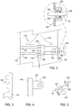
- Figure 1 is a sectional view of one embodiment of a filter housing assembly 100 having a linear damper assembly 130.
- the housing assembly 100 is depicted in Figure 1 as a room-side replaceable filter module, it is contemplated that the benefits and features of the invention may be incorporated in contamination housings, filter diffusers, damper modules and other devices where robust flow control is desired in applications for cleanrooms, environmental and contaminant control, air conditioning, heating and ventilation systems, among other applications.
- the housing assembly 100 generally includes a housing 102 having an inlet 104 and an outlet 106.
- the inlet 104 and the outlet 106 are formed through the housing 102 and allow gases flowing through a duct 110, shown in phantom, to be routed through the housing 102.
- the inlet 104 is bounded by a collar 112 to facilitate coupling the duct 110 to the housing 102.
- a filter element 108 is disposed in the outlet 106 and is sealingly coupled to the housing 102 in a manner that causes gases flowing between the inlet 104 and the outlet 106 to pass through the filter element 108.
- the filter element 108 may be retained in the housing 102 in any suitable manner, for example by a clip 120 or fastener.
- the housing 102 includes an internal flange 114 that sealingly engages the filter element 108.
- the flange 114 includes a knife-edge 116 that sealingly engages a seal 118 coupled to the filter element 108.
- the seal 118 may alternatively be coupled to the housing 102.
- the seal 118 may be a fluid seal, such as a gel, a gas gasket or other material suitable for providing a seal between the housing 102 and filter element 108. It is also contemplated, as in diffuser applications, that the filter element 108 may be potted, bonded, adhered or permanently coupled to the housing 102.
- the damper assembly 130 is disposed in the housing 102 between the inlet 104 and the filter element 108.
- the damper assembly 130 generally includes a damper dish 132, a linear drive mechanism 136 and a bracket 144.
- the bracket 144 is coupled to the housing 102.
- the bracket 144 generally supports and positions the dish 132 and linear drive mechanism 136 within the housing 102.
- the linear drive mechanism 136 is configured to move the dish 132 linearly to open and close the inlet 104.
- the linear drive mechanism 136 may be any actuator suitable for causing the dish 132 to move linearly without rotation.
- linear drive mechanism 136 may be a power screw, solenoid, electric motor, pneumatic cylinder, hydraulic cylinder or cam, scissor actuator, linear actuator among others.
- the actuator 138 includes a rack 138 and a gear 140.
- the rack 138 is coupled to a dish 132 by a fastener 134.
- the dish 132 may be coupled to the rack 138 by other suitable fastening methods.
- the dish 132 includes a flat center section 162 that seats against the flat end of the rack 138.
- the gear 140 is a pinion gear, although another gear or gears may be utilized.
- the pinion gear 140 is coupled to a shaft 152.
- the size of the pinion gear 140 may be selected to provide a predetermined stroke of the rack 138, and to provide a predetermined actuation force.
- the shaft 152 extends through the housing 102 such that the rotational orientation of the pinion gear 140, and thus, the position of the rack 138 and dish 132, may be controlled.
- the shaft 152 may include a key or other suitable connection with the pinion gear 140 that insures efficient transfer of motion between the shaft 152 and pinion gear 140.
- the intermeshing teeth of the rack 138 and pinion gear 140 include flat crests and trenches that prevent the dish 132 from rotating as the rack 138 is advanced.
- the flat crests and trenches of the rack 138 are illustrated in Figure 5 , with the pinion gear 140 being similarly configured.
- the rack 138 is slidably mounted through a set of bushings 142 that are coupled to the bracket 144.
- the bushings 142 may be comprised of any suitable bearing material, such as DELRIN® or brass.
- the bushings 142 may alternatively be roller bearings.
- the rack 138 may be exchanged to provide longer or short actuation strokes which correspondingly sets the orifice area between the dish 132 and the inlet 104.
- the bracket 144 includes a rack support 146 having two tabs 148 extending therefrom.
- the bushings 142 are mounted in the tabs 148 in a spaced-apart relation to enhance control of the motion and orientation of the dish 132.
- the rack support 146 is coupled to one or more cross bars 150 extending between opposite walls of the housing 102.
- the cross bars 150 may be welded, riveted or fastened to the housing 102.
- the dish 132 generally includes a conical face 160 having a sealing section 164 located adjacent a perimeter 166 of the dish 132.
- the sealing section 164 is adapted to engage the housing 102 and/or the collar 112 in a manner that facilitates sealing the air flow through the inlet 104.
- the sealing section 164 includes a channel 168 having a seal 170 disposed therein.
- the seal 170 is configured to engage with a lip 172 extending from one of the collar 112 or the housing 102.
- the seal 170 may be a gasket, bladder or fluid seal. It is also contemplated that the seal 170 may be coupled to the collar 112 or the housing 102 and configured to sealingly engage with the dish 132.
- Figure 2 depicts a partial sectional view of the housing 102 illustrating the shaft 152 extending through the housing 102.
- a bushing 202 is sealably fastened around a hole 204 formed through the housing 102 to facilitate passage of the shaft 152.
- the bushing 202 may be sealed to the housing 102 by any suitable method. In the embodiment depicted in Figure 2 , the bushing 202 is continuously welded to the housing 102.
- a bearing 206 is press-fit into the bushing 202 and engages the shaft 152 to facilitate rotation.
- a seal 208 is disposed in one end of the bushing 202 to prevent air leakage between the bushing 202 and the shaft 152.
- the seal 208 may be an o-ring, cup seal, gasket, fluid seal or other seal suitable for preventing leakage of gas around the shaft 152 and through the hole 204 of the housing 102.
- the shaft 152 includes terminal end 250 disposed outside the housing assembly 100.
- the terminal end 250 generally includes a drive feature 252 that facilitates inducing rotational motion to the shaft 152.
- the drive feature 252 is a flat formed in the sides of the shaft 152.
- Other suitable drive features include, but are not limited to, hex heads, knurled surface, key ways, slots and the like.
- the terminal end 250 is shown extending from the side of the housing 102, it is contemplated that the drive feature 252 may be accessible from the other locations, such as from the outlet-side of the housing 100.
- the inner end of the shaft 152 proximate the pinion gear 140 is supported by a second bearing 304.
- the second bearing 304 is disposed in a tab 302 extending from the rack support 146.
- the second bearing 304 may be similar to the bearing 206.
- the shaft 152 is selectively rotated to rotate the pinion gear 140.
- the rotating pinion gear 140 advances the rack 138, thereby linearly moving the dish 132.
- the seal 170 uniformly engages the lip 172, thereby enhancing seal uniformity and performance.
- the dish 132 is maintained centered relative to the flow entering (or exiting) the housing 102 through the inlet 104, the flow orifice defined between the dish 132 and lip 172 is uniform, thus, promoting flow uniformity through the filter element 108.
- the dish 132 is illustratively shown in a position closing and spaced from the inlet 104 in Figures 8-9 .
- the spacing of the dish 132 from the lip 172 may be selected to provide a desired air flow rate through the filter element 108.
- Figure 6 is a sectional view of one embodiment of a contamination housing assembly 600.
- a contamination housing assembly that may be adapted to benefit from the invention is available from Camfil Farr, Inc., located in Riverdale, New Jersey.
- the housing assembly 600 includes a housing 602 having an inlet 604, an outlet 606 and at least one access port 608.
- the inlet 604 and outlet 606 are formed through the housing 602 and arrange to direct gases flowing through the housing 602.
- the access port 608 is configured to permit access to the interior of the housing 602, for example, for filter change-out, scanning a filter disposed in an adjacently coupled housing, and the like.
- the housing 602 may be fabricated from a metal, such as aluminum, steel and stainless steel, or other suitable material.
- the housing 602 has a construction that forms a pressure barrier between gases flowing therethrough and an environment outside the housing 602.
- the housing 602 is a hollow rectangular body fabricated from continuously welded metal sheets.
- the housing 602 additionally includes sealing flange 614 that sealingly engages a filter element 616 disposed in the housing assembly 600.
- a linkage mechanism 620 is provided in the housing 602 and is configured to move the filter element 616 between a position sealingly engaged with the flange 614 and a position clear of the flange 614.
- a seal not shown, like the seal 170 described above, is disposed between the filter element 616 and flange 164 to prevent flow from bypassing the filter element 616.
- the access port 608 is configured to facilitate removal of the filter element 616 from the housing 602 and is selectively sealed by a door 622.
- the access port 608 is circumscribed by a bagging ring (not shown) that is utilized to access the interior of the housing and/or remove and replace the filter element 616.
- At least one end of the contamination housing 600 includes a linear damper assembly 130.
- the linear damper assembly 130 is as described above.
- an external actuator 690 is coupled to the shaft 152 of the damper assembly 130 on the exterior of the housing 602.
- the external actuator 690 may be any device or object suitable for controlling the rotation of the shaft 152.
- the external actuator 690 is a wheel. It is contemplated that the external actuator 690 may alternatively be a motor, pneumatic cylinder, hydraulic cylinder or a lever, among others.
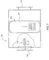
- FIG. 7 depicts one embodiment of a housing assembly 700 having a damper assembly 130.
- the housing 700 may be configured with or without an access port 608.
- the housing assembly 700 may be utilized as a stand-alone damper (shutoff and/or flow control), or as an access port in a containment system, among others.
- the damper assembly 130 may be operated as described with reference to the embodiments above to control flow through the housing assembly 700.
- a housing assembly having an integrated linear damper assembly as described above was tested to determine if any significant or adverse amount of wear will occur between the fabricated pinion gear and rack (both fabricated from stainless steel); and if any significant or adverse amount of wear will occur in the bronze bushings used to support the rack and the damper shaft.
- a one-high by one-wide containment housing was modified to accept the integrated linear damper assembly.
- the integrated damper assembly utilized a 12" diameter stainless steel dish.
- a medium durometer silicone sponge gasket was cut by hand using a template. RTV was placed in the bottom of the channel of the dish. The gasket was seated in the channel, using the RTV as an adhesive to hold the gasket in the channel. The edges of the sponge gasket were not sealed in the channel, in order to test the seal with minimum adhesion to the dish.
- the damper actuator included a three quarter inch diameter stainless steel shaft with keyway, which is typically used on conventional flat blade dampers.
- a pinion gear was fabricated from one quarter inch thick 304 stainless steel. Three gear pieces were stacked on top of each other with the keyways aligned and welded together to form a single gear about three quarter inch thick.
- the rack was manufactured from 20mm diameter, 304 stainless steel shaft. The rack travels in a linear fashion and was held in place and aligned using bronze bushings coupled to the bracket. A bronze bushing was also installed in a support member to hold and align the damper shaft and assure proper meshing of the gear teeth with the rack.
- a lip extending from a 12 inch (304.8 mm) diameter, 304 stainless steel collar circumscribing the inlet was used to form that knife-edge circumscribing the inlet.
- the collar was continuously welded to a piece of 11 gauge 304 stainless steel that was continuously welded to the upstream flange of the housing.
- the rack As an actuator coupled to the damper assembly rotated to turn the pinion gear, the rack is advanced linearly toward the inlet.
- the rack pushes the stainless steel dish toward the knife-edge mounted in the endplate of the housing.
- the flat form of the teeth of the rack, engaged with the flat form of the teeth of the shaft substantially prevents rotation of the shaft.
- the damper was bubble-tested in accordance with CFW-1000 CFW-10003, Revision 3: Pressure Decay / Structural Capability / Bubble Leak Testing.
- the containment housing with integrated damper was placed on a cart and a blank-off plate with ball valve and static pressure port was attached to the opposite end of the inlet collar that also serves as the knife-edge. This space was pressurized such that the damper was being pushed away from the knife-edge.
- the pressure was measured with a U-tube manometer that provided a differential pressure reading between the pressurized space and atmospheric pressure. Soap solution was sprayed on the interface between the knife-edge on the inlet ring and the silicone gasket that it was sealing against. Visual inspections were conducted for a period of 5 minutes to ensure bubble-tightness (i.e., a leak free condition).
- bubble-tight dampers are bubble-leak tested at >+10" water gauge (w.g.) (2.50 kPa). In some circumstances, they are required to be bubble-tight at >+15" w.g. (3.74 kPa). During this test, the linear damper was tested at >+18" w.g. (4.48 kPa).
- Bubble-tests were conducted after more than 5,000, 10,000 and 15,000 cycles using the method described above. Visual observations were conducted throughout the entire test to determine the effect of rapid repeated cycling on the durability of the seal and actuation mechanism.
- the damper was bubble-tight at >+18" w.g. (4.48 kPa) for each test conducted. It is believed that the damper would remain bubble-tight at higher pressures.
- the test was terminated after 15,260 cycles without failure to facilitate use of the lab for other projects. Upon visual observation and inspection of the mechanism for damper actuation after conclusion of the test, no evidence of mechanism wear, degradation or failure was apparent. There also was no visual evidence of gear wear.
- the tested damper assembly compares favorably to conventional flat-blade dampers and dish-style dampers.
- the extended life is believed attributable to the design and construction of the damper assembly, which utilizes linear motion that has reduce bushing wear and stress compared to rotating blade. Moreover, the linear motion and the use of gearing reduces the power required to close the damper, thereby minimizing actuator costs.
- the damper was proven to remain bubble-tight at >+18" w.g. (4.48 kPa) at more than 15,000 cycles, which is 50 percent greater than the industry requirements (bubble-tight at +10" w.g. (2.50 kPa) after 10,000 cycles).
- the robustness and durability of the mechanism are superior to both the flat-blade damper and dish-style damper designs, as proven by the lack of wear even after more than 15,000 cycles.
Description
- This application claims benefit from United States Provisional Patent Application Serial No.
60/729,644, filed October 24, 2005 - The present invention generally relates to a housing assembly having an integrated damper, and more specifically, a housing assembly for an air filter having an integrated damper with a linear drive mechanism.
- Cleanrooms are utilized in many industries for contamination control and to improve product yields. A plurality of filters, typically mounted in the ceiling of the cleanroom, are configured to remove particulate from air entering the cleanroom at a predetermined efficiency selected based upon the cleanliness requirements of the activities performed in the cleanroom. As particulates load the filtration media disposed in the filter, the airflow through the filter decreases as the pressure drop across the filter increases. Once the filter reaches a critical pressure drop, the filter is typically replaced.
- On other applications, replacement of filters is scheduled based on time or processes performed within the cleanroom. For example, in many pharmaceutical and biotech cleanrooms, periodic replacement of filters is required to meet regulatory or owner specifications. To facilitate efficient replacement of the filter, a hood (housing) is typically mounted in the cleanroom ceiling in which the filter may be readily removed and replaced.
- Ducted supply hoods with roomside replaceable filters are commonly used in pharmaceutical applications for cleaning supply air to cleanroom manufacturing and process areas, as well as to laboratory areas. Most of these hoods are supplied with adjustable dampers that allow customers to regulate the airflow without having to remove the filter from the hood. The most common types of dampers are guillotine, opposed blade and butterfly types. When completely closed, these dampers essentially stop the flow of air to the hood. In many cases, the leakage through a closed damper is negligible in terms of flow rate, but is significant when considered in the terms of contamination of a cleanroom.
- Because these types of dampers do not provide a seal (i.e., are not leak-free or bubble-tight), they are inadequate when it comes to decontamination processes that require complete isolation of the cleanroom. For example, during routine testing and validation of filters installed in a pharmaceutical facility, one or more filters may be found damaged, leaking and/or requiring replacement. When a technician removes that filter from the hood, the "seal" between the cleanroom and the contaminated plenum and supply ducts upstream of the removed filter is broken. When the new filter is installed, the "seal" between those two areas is restored, but the cleanroom has already been contaminated by air and particulate entering the cleanroom from the contaminated area of the plenum and supply ducts. Thus, the facility owner must perform a decontamination process of the entire room before resuming cleanroom operations. This is a very time-consuming and costly process.
- Therefore, there is a need for a filter housing assembly having improved sealing capabilities.
US 4,884,590 discloses a motor driven air valve comprising a unitary damper assembly. The damper assembly includes a generally planar damper mounted for movement axially of the inlet section. Because a portion of the damper assembly is splined, the damper cannot rotate and is driven axially within the valve by the rotation of the drive motor and drive gear. - The filter housing assembly according to the invention is defined by independent claim 1. Embodiments are defined by the dependent claims. Embodiments of the invention generally include a housing assembly having an integrated damper with a linear drive mechanism. In one embodiment, a housing assembly includes a housing having an inlet and an outlet. A damper is disposed in the housing and is positionable to regulate flow entering the housing through the inlet. A linear drive mechanism is operably coupled to the damper and is adapted to linearly move the damper between positions that are spaced-apart from the housing and a position that closes the inlet. The linear drive mechanism is configured to move the damper linearly without rotating the damper.
- In another embodiment, the damper has a non-planar shape that extends into the inlet when the damper is in a closed position. A means is provided for restraining the damper from rotating.
- In another embodiment, a housing assembly includes an inlet port, an outlet port and a bag in/bag out filter access port. A filter receiving mechanism is disposed in the housing and is configured to direct gases flowing between the inlet and outlet ports through a filter installed in the housing. A first damper is disposed in the housing and is movable between positions that open and close the inlet port. A second damper is also disposed in the housing and is movable between positions that open and close the outlet port. A mechanism is provided in the housing that is configured to move the first damper between the open and closed positions without rotating the first damper, wherein the first damper is spaced apart from the housing when in the open position.
- The teachings of the present invention can be readily understood by considering the following detailed description in conjunction with the accompanying drawings, in which:
-
Figure 1 is a cross-sectional view of one embodiment of a linear damper assembly disposed in a filter housing assembly; -
Figure 2 is a partial sectional view of the housing assembly ofFigure 1 ; -
Figure 3 is a top view of a portion of an actuator adapted for linearly moving a dish of the damper assembly; -
Figure 4 is a side view of a bushing; -
Figure 5 is a partial side view of a rack of the actuator; -
Figure 6 is a side cut-away view of one embodiment of a linear damper assembly disposed in a contamination housing assembly; -
Figure 7 is another embodiment of a linear damper assembly disposed in a housing assembly; -
Figure 8 is a perspective view of one embodiment of the linear damper assembly in an open position; and -
Figure 9 is a perspective view of the linear damper assembly in a closed position. - To facilitate understanding, identical reference numerals have been used, where possible, to designate identical elements that are common to the figures. It is contemplated that elements and features of one embodiment may be beneficially incorporated in other embodiments without further recitation.
- It is to be noted, however, that the appended drawings illustrate only exemplary embodiments of this invention and are therefore not to be considered limiting of its scope, for the invention may admit to other equally effective embodiments.
-
Figure 1 is a sectional view of one embodiment of afilter housing assembly 100 having alinear damper assembly 130. Although thehousing assembly 100 is depicted inFigure 1 as a room-side replaceable filter module, it is contemplated that the benefits and features of the invention may be incorporated in contamination housings, filter diffusers, damper modules and other devices where robust flow control is desired in applications for cleanrooms, environmental and contaminant control, air conditioning, heating and ventilation systems, among other applications. - The
housing assembly 100 generally includes ahousing 102 having aninlet 104 and anoutlet 106. Theinlet 104 and theoutlet 106 are formed through thehousing 102 and allow gases flowing through aduct 110, shown in phantom, to be routed through thehousing 102. Theinlet 104 is bounded by acollar 112 to facilitate coupling theduct 110 to thehousing 102. Afilter element 108 is disposed in theoutlet 106 and is sealingly coupled to thehousing 102 in a manner that causes gases flowing between theinlet 104 and theoutlet 106 to pass through thefilter element 108. Thefilter element 108 may be retained in thehousing 102 in any suitable manner, for example by aclip 120 or fastener. - In the embodiment depicted in
Figure 1 , thehousing 102 includes aninternal flange 114 that sealingly engages thefilter element 108. In one embodiment, theflange 114 includes a knife-edge 116 that sealingly engages aseal 118 coupled to thefilter element 108. Theseal 118 may alternatively be coupled to thehousing 102. Theseal 118 may be a fluid seal, such as a gel, a gas gasket or other material suitable for providing a seal between thehousing 102 andfilter element 108. It is also contemplated, as in diffuser applications, that thefilter element 108 may be potted, bonded, adhered or permanently coupled to thehousing 102. - The
damper assembly 130 is disposed in thehousing 102 between theinlet 104 and thefilter element 108. Thedamper assembly 130 generally includes adamper dish 132, alinear drive mechanism 136 and abracket 144. Thebracket 144 is coupled to thehousing 102. Thebracket 144 generally supports and positions thedish 132 andlinear drive mechanism 136 within thehousing 102. Thelinear drive mechanism 136 is configured to move thedish 132 linearly to open and close theinlet 104. - Referring back to
Figure 1 , thelinear drive mechanism 136 may be any actuator suitable for causing thedish 132 to move linearly without rotation. For example,linear drive mechanism 136 may be a power screw, solenoid, electric motor, pneumatic cylinder, hydraulic cylinder or cam, scissor actuator, linear actuator among others. In the embodiment depicted inFigure 1 , theactuator 138 includes arack 138 and agear 140. Therack 138 is coupled to adish 132 by afastener 134. It is contemplated that thedish 132 may be coupled to therack 138 by other suitable fastening methods. To insure a perpendicular orientation between thedish 132 and therack 138, thedish 132 includes aflat center section 162 that seats against the flat end of therack 138. - In the embodiment depicted in
Figure 1 , thegear 140 is a pinion gear, although another gear or gears may be utilized. Thepinion gear 140 is coupled to ashaft 152. The size of thepinion gear 140 may be selected to provide a predetermined stroke of therack 138, and to provide a predetermined actuation force. In one embodiment, theshaft 152 extends through thehousing 102 such that the rotational orientation of thepinion gear 140, and thus, the position of therack 138 anddish 132, may be controlled. Theshaft 152 may include a key or other suitable connection with thepinion gear 140 that insures efficient transfer of motion between theshaft 152 andpinion gear 140. In one embodiment, the intermeshing teeth of therack 138 andpinion gear 140 include flat crests and trenches that prevent thedish 132 from rotating as therack 138 is advanced. The flat crests and trenches of therack 138 are illustrated inFigure 5 , with thepinion gear 140 being similarly configured. - The
rack 138 is slidably mounted through a set ofbushings 142 that are coupled to thebracket 144. Thebushings 142 may be comprised of any suitable bearing material, such as DELRIN® or brass. Thebushings 142 may alternatively be roller bearings. Therack 138 may be exchanged to provide longer or short actuation strokes which correspondingly sets the orifice area between thedish 132 and theinlet 104. - In the embodiment depicted in
Figure 1 , thebracket 144 includes arack support 146 having twotabs 148 extending therefrom. Thebushings 142 are mounted in thetabs 148 in a spaced-apart relation to enhance control of the motion and orientation of thedish 132. Therack support 146 is coupled to one or more cross bars 150 extending between opposite walls of thehousing 102. The cross bars 150 may be welded, riveted or fastened to thehousing 102. - The
dish 132 generally includes a conical face 160 having a sealingsection 164 located adjacent aperimeter 166 of thedish 132. Thesealing section 164 is adapted to engage thehousing 102 and/or thecollar 112 in a manner that facilitates sealing the air flow through theinlet 104. In the embodiment depicted inFigure 1 , thesealing section 164 includes achannel 168 having aseal 170 disposed therein. Theseal 170 is configured to engage with alip 172 extending from one of thecollar 112 or thehousing 102. Theseal 170 may be a gasket, bladder or fluid seal. It is also contemplated that theseal 170 may be coupled to thecollar 112 or thehousing 102 and configured to sealingly engage with thedish 132. The non-rotation of thedish 132 provided by therack 138 andpinion gear 140 discussed above, prevents shearing of the seal as thedish 132 andlip 170 engage, thereby extending the life and performance of the seal. It is contemplated that thedish 132 may rotate when spaced from the closed position, as long as thelinear drive mechanism 136 does not cause thedish 132 to rotate while sealing theinlet 104. -
Figure 2 depicts a partial sectional view of thehousing 102 illustrating theshaft 152 extending through thehousing 102. To prevent leakage from thehousing assembly 100 around theshaft 152, abushing 202 is sealably fastened around ahole 204 formed through thehousing 102 to facilitate passage of theshaft 152. Thebushing 202 may be sealed to thehousing 102 by any suitable method. In the embodiment depicted inFigure 2 , thebushing 202 is continuously welded to thehousing 102. - A
bearing 206 is press-fit into thebushing 202 and engages theshaft 152 to facilitate rotation. Aseal 208 is disposed in one end of thebushing 202 to prevent air leakage between thebushing 202 and theshaft 152. Theseal 208 may be an o-ring, cup seal, gasket, fluid seal or other seal suitable for preventing leakage of gas around theshaft 152 and through thehole 204 of thehousing 102. - The
shaft 152 includesterminal end 250 disposed outside thehousing assembly 100. Theterminal end 250 generally includes adrive feature 252 that facilitates inducing rotational motion to theshaft 152. In one embodiment, thedrive feature 252 is a flat formed in the sides of theshaft 152. Other suitable drive features include, but are not limited to, hex heads, knurled surface, key ways, slots and the like. Although theterminal end 250 is shown extending from the side of thehousing 102, it is contemplated that thedrive feature 252 may be accessible from the other locations, such as from the outlet-side of thehousing 100. - Referring to
Figures 3-4 , the inner end of theshaft 152 proximate thepinion gear 140 is supported by asecond bearing 304. Thesecond bearing 304 is disposed in atab 302 extending from therack support 146. Thesecond bearing 304 may be similar to thebearing 206. - In operation, the
shaft 152 is selectively rotated to rotate thepinion gear 140. Therotating pinion gear 140 advances therack 138, thereby linearly moving thedish 132. As the motion of thedish 132 is substantially perpendicular to the plane of the opening defined by theinlet 104, theseal 170 uniformly engages thelip 172, thereby enhancing seal uniformity and performance. Moreover, as thedish 132 is maintained centered relative to the flow entering (or exiting) thehousing 102 through theinlet 104, the flow orifice defined between thedish 132 andlip 172 is uniform, thus, promoting flow uniformity through thefilter element 108. Thedish 132 is illustratively shown in a position closing and spaced from theinlet 104 inFigures 8-9 . The spacing of thedish 132 from thelip 172 may be selected to provide a desired air flow rate through thefilter element 108. -
Figure 6 is a sectional view of one embodiment of acontamination housing assembly 600. A contamination housing assembly that may be adapted to benefit from the invention is available from Camfil Farr, Inc., located in Riverdale, New Jersey. - In one embodiment, the
housing assembly 600 includes ahousing 602 having aninlet 604, anoutlet 606 and at least oneaccess port 608. Theinlet 604 andoutlet 606 are formed through thehousing 602 and arrange to direct gases flowing through thehousing 602. Theaccess port 608 is configured to permit access to the interior of thehousing 602, for example, for filter change-out, scanning a filter disposed in an adjacently coupled housing, and the like. - The
housing 602 may be fabricated from a metal, such as aluminum, steel and stainless steel, or other suitable material. Thehousing 602 has a construction that forms a pressure barrier between gases flowing therethrough and an environment outside thehousing 602. In the embodiment depicted inFigure 6 , thehousing 602 is a hollow rectangular body fabricated from continuously welded metal sheets. - The
housing 602 additionally includes sealingflange 614 that sealingly engages afilter element 616 disposed in thehousing assembly 600. Alinkage mechanism 620 is provided in thehousing 602 and is configured to move thefilter element 616 between a position sealingly engaged with theflange 614 and a position clear of theflange 614. A seal, not shown, like theseal 170 described above, is disposed between thefilter element 616 andflange 164 to prevent flow from bypassing thefilter element 616. - The
access port 608 is configured to facilitate removal of thefilter element 616 from thehousing 602 and is selectively sealed by adoor 622. Theaccess port 608 is circumscribed by a bagging ring (not shown) that is utilized to access the interior of the housing and/or remove and replace thefilter element 616. - At least one end of the
contamination housing 600 includes alinear damper assembly 130. Thelinear damper assembly 130 is as described above. In the embodiment depicted inFigure 6 , anexternal actuator 690 is coupled to theshaft 152 of thedamper assembly 130 on the exterior of thehousing 602. Theexternal actuator 690 may be any device or object suitable for controlling the rotation of theshaft 152. In one embodiment, theexternal actuator 690 is a wheel. It is contemplated that theexternal actuator 690 may alternatively be a motor, pneumatic cylinder, hydraulic cylinder or a lever, among others. -
Figure 7 depicts one embodiment of ahousing assembly 700 having adamper assembly 130. Thehousing 700 may be configured with or without anaccess port 608. Thehousing assembly 700 may be utilized as a stand-alone damper (shutoff and/or flow control), or as an access port in a containment system, among others. Thedamper assembly 130 may be operated as described with reference to the embodiments above to control flow through thehousing assembly 700. - A housing assembly having an integrated linear damper assembly as described above was tested to determine if any significant or adverse amount of wear will occur between the fabricated pinion gear and rack (both fabricated from stainless steel); and if any significant or adverse amount of wear will occur in the bronze bushings used to support the rack and the damper shaft.
- A one-high by one-wide containment housing was modified to accept the integrated linear damper assembly. The integrated damper assembly utilized a 12" diameter stainless steel dish. A medium durometer silicone sponge gasket was cut by hand using a template. RTV was placed in the bottom of the channel of the dish. The gasket was seated in the channel, using the RTV as an adhesive to hold the gasket in the channel. The edges of the sponge gasket were not sealed in the channel, in order to test the seal with minimum adhesion to the dish.
- The damper actuator included a three quarter inch diameter stainless steel shaft with keyway, which is typically used on conventional flat blade dampers. A pinion gear was fabricated from one quarter inch thick 304 stainless steel. Three gear pieces were stacked on top of each other with the keyways aligned and welded together to form a single gear about three quarter inch thick. The rack was manufactured from 20mm diameter, 304 stainless steel shaft. The rack travels in a linear fashion and was held in place and aligned using bronze bushings coupled to the bracket. A bronze bushing was also installed in a support member to hold and align the damper shaft and assure proper meshing of the gear teeth with the rack.
- A lip extending from a 12 inch (304.8 mm) diameter, 304 stainless steel collar circumscribing the inlet was used to form that knife-edge circumscribing the inlet. The collar was continuously welded to a piece of 11
gauge 304 stainless steel that was continuously welded to the upstream flange of the housing. - As an actuator coupled to the damper assembly rotated to turn the pinion gear, the rack is advanced linearly toward the inlet. The rack pushes the stainless steel dish toward the knife-edge mounted in the endplate of the housing. The silicone gasket around the perimeter of the dish sealed against the knife-edge. In one embodiment, the flat form of the teeth of the rack, engaged with the flat form of the teeth of the shaft substantially prevents rotation of the shaft.
-
- Elomatic 350 Series Pneumatic Actuator with spring return
- ∘ Model: ESO350.U2A03B.27K0
- ∘ Serial No.: 22221100020
- Blank-off Plate with Ball Valve and static pressure connection
- OMRON Timer:
∘ Model: H3CR-F8300 - Dwyer Flex-Tube Manometer:
- Gast Vacuum Pump
- The damper was bubble-tested in accordance with CFW-1000 CFW-10003, Revision 3: Pressure Decay/Structural Capability/Bubble Leak Testing. The containment housing with integrated damper was placed on a cart and a blank-off plate with ball valve and static pressure port was attached to the opposite end of the inlet collar that also serves as the knife-edge. This space was pressurized such that the damper was being pushed away from the knife-edge. The pressure was measured with a U-tube manometer that provided a differential pressure reading between the pressurized space and atmospheric pressure. Soap solution was sprayed on the interface between the knife-edge on the inlet ring and the silicone gasket that it was sealing against. Visual inspections were conducted for a period of 5 minutes to ensure bubble-tightness (i.e., a leak free condition).
- Generally, bubble-tight dampers are bubble-leak tested at >+10" water gauge (w.g.) (2.50 kPa). In some circumstances, they are required to be bubble-tight at >+15" w.g. (3.74 kPa). During this test, the linear damper was tested at >+18" w.g. (4.48 kPa).
- After the initial bubble-test, power and compressed air were supplied to the actuator, and the damper was cycled between open and closed positions. Bubble-tests were conducted after more than 5,000, 10,000 and 15,000 cycles using the method described above. Visual observations were conducted throughout the entire test to determine the effect of rapid repeated cycling on the durability of the seal and actuation mechanism.
- The results of the cycle tests are as follows:
Table 1: Cycle Test Results Cumulative # of Cycles Pressure Pass or Fail Comments 0 >17" w.g. (4.23 kPa) Pass Initial Test 5585 >28" w.g. (6.97 kPa) Pass Damper was left closed the previous night. Indentation in silicone gasket, but still passed the bubble-tight test. No indication of mechanism wear. 10,289 >+18" w.g. (4.48 kPa) Pass Damper was left closed the previous night. Indentation in silicone gasket, but still passed the bubble-tight test. No indication of mechanism wear. 15,260 >+18" w.g. (4.48 kPa) Pass Damper was left closed the previous night. Indentation in silicone gasket, but still passed the bubble-tight test. No indication of mechanism wear. - As shown in Table 1, the damper was bubble-tight at >+18" w.g. (4.48 kPa) for each test conducted. It is believed that the damper would remain bubble-tight at higher pressures. The test was terminated after 15,260 cycles without failure to facilitate use of the lab for other projects. Upon visual observation and inspection of the mechanism for damper actuation after conclusion of the test, no evidence of mechanism wear, degradation or failure was apparent. There also was no visual evidence of gear wear.
- The tested damper assembly compares favorably to conventional flat-blade dampers and dish-style dampers. The extended life is believed attributable to the design and construction of the damper assembly, which utilizes linear motion that has reduce bushing wear and stress compared to rotating blade. Moreover, the linear motion and the use of gearing reduces the power required to close the damper, thereby minimizing actuator costs.
- The damper was proven to remain bubble-tight at >+18" w.g. (4.48 kPa) at more than 15,000 cycles, which is 50 percent greater than the industry requirements (bubble-tight at +10" w.g. (2.50 kPa) after 10,000 cycles). The robustness and durability of the mechanism are superior to both the flat-blade damper and dish-style damper designs, as proven by the lack of wear even after more than 15,000 cycles.
- Although various embodiments which incorporate the teachings of the present invention have been shown and described in detail herein, those skilled in the art can readily devise many other varied embodiment that still incorporate these teachings.
Claims (12)
- A filter housing assembly (100;600;700), comprising:
a housing (102;602) having an inlet (104:604),an outlet (106;606) and an internal flange for sealingly engaging a filter element, a damper (132) movable between positions that open and close the inlet (102;602), and means for moving the damper, wherein the damper (132) is disposed in the housing (102;602) in an orientation that remains centered with respect to the inlet, and that the means for moving the damper is a linear drive mechanism (136) adapted to move the damper (132) linearly without rotation thereof, wherein the linear drive mechanism comprises a rack (138) and a pinion gear (140) that prevent rotation of the damper when the rack is moved in a linear direction, and wherein the damper is fixed to the rack. - The filter housing assembly (100;600;700) according to claim 1, wherein the damper (132) has a non-planar shape that extends into the inlet when the damper is in the closed position.
- The filter housing assembly (100;600;700) according to claim 2, wherein the damper (132) is substantially conical.
- The filter housing assembly (102) according to any one of the preceding claims, wherein the filter element (108) is disposed in the housing (102).
- The filter housing assembly (100;600) according to any one of the preceding claims, further comprising a seal (170) interfacing the damper (132) and the housing (102;602) to providing a bubble-tight seal of the inlet (104;604) when the damper is in closed position.
- The filter housing assembly (100;600) according to claim 5, wherein said seal (170) is coupled to a perimeter of the damper (132).
- The filter housing assembly (100;600) according to claim 5 or 6, wherein the seal (170) is a gasket, bladder or fluid seal.
- The filter housing assembly (100;600;700) according to any of the preceding claims, wherein the means for preventing rotation of the damper (132) comprises a first feature coupled to the housing (102;602) and fixed in orientation relative to the housing, and a second feature fixed in orientation relative to the damper (132), wherein the second feature engages the first feature in a manner that permits linear motion without rotation.
- The filter housing assembly (100;600;700) according to any of the preceding claims, wherein the means for preventing rotation of the damper (132) comprises mating threaded members (138,140) having truncated crests and valleys.
- The filter housing assembly (100;600;700) according to any of the preceding claims , wherein the rack (138) has a non-circular cross section, and a bearing or guide (142) circumscribing the rack, wherein the bearing or guide has a rack accepting aperture mating the shape of the rack (138).
- The filter housing assembly (600;700) according to any of the preceding claims , comprising a bag in/bag out filter access port (608), and a filter receiving mechanism disposed in the housing and configured to direct gases flowing between the inlet and the outlet through a filter installed in the housing.
- The filter housing assembly (600) according to any of the preceding claims, wherein a second damper movable between positions that open and close the outlet (606) is provided, said second damper being similar to the damper (132) movable between positions that open and close the inlet (604) and being driven by a drive mechanism similar to the drive mechanism for the damper movable between positions that open and close the inlet.
Priority Applications (1)
| Application Number | Priority Date | Filing Date | Title |
|---|---|---|---|
| PL06817352T PL1941193T3 (en) | 2005-10-24 | 2006-10-24 | Linear drive for integrated damper |
Applications Claiming Priority (2)
| Application Number | Priority Date | Filing Date | Title |
|---|---|---|---|
| US72964405P | 2005-10-24 | 2005-10-24 | |
| PCT/US2006/041519 WO2007050626A1 (en) | 2005-10-24 | 2006-10-24 | Linear drive for integrated damper |
Publications (3)
| Publication Number | Publication Date |
|---|---|
| EP1941193A1 EP1941193A1 (en) | 2008-07-09 |
| EP1941193A4 EP1941193A4 (en) | 2013-01-23 |
| EP1941193B1 true EP1941193B1 (en) | 2019-04-03 |
Family
ID=37968150
Family Applications (1)
| Application Number | Title | Priority Date | Filing Date |
|---|---|---|---|
| EP06817352.5A Active EP1941193B1 (en) | 2005-10-24 | 2006-10-24 | Linear drive for integrated damper |
Country Status (10)
| Country | Link |
|---|---|
| US (1) | US20070093196A1 (en) |
| EP (1) | EP1941193B1 (en) |
| JP (1) | JP5275807B2 (en) |
| CN (1) | CN101297141B (en) |
| CA (1) | CA2625690C (en) |
| DK (1) | DK1941193T3 (en) |
| ES (1) | ES2729840T3 (en) |
| PL (1) | PL1941193T3 (en) |
| SG (1) | SG180042A1 (en) |
| WO (1) | WO2007050626A1 (en) |
Families Citing this family (10)
| Publication number | Priority date | Publication date | Assignee | Title |
|---|---|---|---|---|
| US8404023B1 (en) | 2010-06-08 | 2013-03-26 | Aaf-Mcquay Inc. | Air handling filtration equipment with adjustable media bed and method of use |
| US8956207B2 (en) * | 2011-12-13 | 2015-02-17 | Controlled Holdings, Llc | Barometric relief air zone damper |
| CN202470348U (en) * | 2012-02-29 | 2012-10-03 | 珠海格力电器股份有限公司 | Air deflector driving device and air conditioner indoor unit with same |
| EP3170545B1 (en) | 2015-11-23 | 2019-12-25 | Skan Ag | Filter system for a containment passed through by a gas stream |
| CN109307078A (en) * | 2018-10-30 | 2019-02-05 | 温州周泰阀门管件有限公司 | A kind of sanitation-grade valve opening and closing element |
| KR102028301B1 (en) * | 2019-03-13 | 2019-10-02 | 김대종 | Steamed rice manufacturing apparatus |
| CN110160243B (en) * | 2019-05-17 | 2022-02-22 | 青岛海尔空调电子有限公司 | Control method of ceiling type air conditioner |
| CN110160236B (en) * | 2019-05-17 | 2022-05-20 | 青岛海尔空调电子有限公司 | Control method of ceiling type air conditioner |
| JP7000395B2 (en) * | 2019-10-15 | 2022-01-19 | 森六テクノロジー株式会社 | Air conditioning outlet device |
| CN112161363A (en) * | 2020-09-29 | 2021-01-01 | 谭浩 | Ventilation energy-saving system of green building |
Family Cites Families (30)
| Publication number | Priority date | Publication date | Assignee | Title |
|---|---|---|---|---|
| US1460785A (en) * | 1921-03-25 | 1923-07-03 | Buckley John | Control mechanism |
| US3402530A (en) * | 1962-08-21 | 1968-09-24 | Israel State | Air filter installations |
| US3354616A (en) * | 1964-11-20 | 1967-11-28 | Saint Gobain Nucleaire | Method and apparatus for loading and unloading a filter for radioactive gases |
| US3323437A (en) * | 1965-08-20 | 1967-06-06 | Weber Showcase & Fixture Co | Filter system |
| US3533780A (en) * | 1966-02-10 | 1970-10-13 | Sumitomo Metal Ind | High-strength austenitic stainless steel for a boiler |
| US3537380A (en) * | 1968-01-22 | 1970-11-03 | Wehr Corp | Variable volume distributor adapted to provide uniform throw |
| CA1013609A (en) * | 1974-02-18 | 1977-07-12 | Hans R. Keller | Method of and apparatus for controlling the inlet openings of central ventilation installations |
| US3987812A (en) * | 1975-11-10 | 1976-10-26 | Enterprise Brass Works | Adapter valve |
| GB2064068B (en) * | 1979-11-20 | 1983-11-02 | Hall Thermotank Int Ltd | Valve unit for ventilating medium |
| US4334869A (en) * | 1980-05-30 | 1982-06-15 | Wilcox Charles E | Educational mathematics game |
| DE3045396A1 (en) * | 1980-12-02 | 1982-07-01 | Kessler & Luch Gmbh, 6300 Giessen | Ventilator air flow controlled by moving throttle - in apertured pipe extension spaced from housing wall |
| US4450964A (en) * | 1983-02-22 | 1984-05-29 | Flanders Filters, Inc. | Protective plastic bag and method of utilizing the same to remove articles from a hepa filter housing |
| US4519301A (en) * | 1984-01-12 | 1985-05-28 | Wetzel Lawrence E | Air flow balancing fire damper |
| US4557185A (en) * | 1984-07-26 | 1985-12-10 | Harriman Ronald M | Solenoid operated exhaust air damper |
| CH664806A5 (en) * | 1985-07-01 | 1988-03-31 | Marius Thiebaud | AUTOMATIC VALVE FOR REGULATING THE AIR FLOW SUPPORTED FROM A PREMISES BY A MECHANICAL VENTILATION INSTALLATION. |
| US4716818A (en) * | 1986-03-03 | 1988-01-05 | Air Concepts, Inc. | Air distribution device |
| US4800804A (en) * | 1987-08-06 | 1989-01-31 | Tennessee Plastics, Inc. | Variable air flow diffuser |
| JPH0433941Y2 (en) * | 1987-08-31 | 1992-08-13 | ||
| US4884590A (en) * | 1988-12-05 | 1989-12-05 | American Standard Inc. | Electric motor driven air valve |
| DE3928621C2 (en) * | 1989-08-30 | 1995-03-30 | Krantz Tkt Gmbh | Bottom source outlet |
| US6149699A (en) * | 1992-12-14 | 2000-11-21 | Grantham; James I. | Method and apparatus relating to disposable filter modules for filtering air containing hazardous substances |
| US5643081A (en) * | 1996-07-11 | 1997-07-01 | Klein; James A. | Vent screen and vent apparatus |
| JP3748953B2 (en) * | 1996-08-30 | 2006-02-22 | 三洋電機株式会社 | Motorized valve and absorption refrigerator using motorized valve |
| US5837040A (en) * | 1996-09-09 | 1998-11-17 | International Decontamination Systems Llc | Room air decontamination device |
| JP4449207B2 (en) * | 2000-11-15 | 2010-04-14 | パナソニック株式会社 | Shut-off valve |
| US6780098B2 (en) * | 2002-02-15 | 2004-08-24 | Nifco Inc. | Regulator for air outlet |
| JP2004132646A (en) * | 2002-10-11 | 2004-04-30 | Ishikawajima Harima Heavy Ind Co Ltd | Exhaust port structure with filter and filter replacement method therefor |
| WO2005115080A2 (en) * | 2004-05-27 | 2005-12-08 | E.H. Price Ltd. | Modular floor terminal with damper |
| US7220291B2 (en) * | 2004-06-08 | 2007-05-22 | Camfil Farr, Inc. | Filter housing assembly |
| US7470176B2 (en) * | 2005-10-14 | 2008-12-30 | Flow Safe Inc | Converting existing prior art fume hoods into high performance low airflow stable vortex fume hoods |
-
2006
- 2006-10-24 SG SG2010078350A patent/SG180042A1/en unknown
- 2006-10-24 JP JP2008537885A patent/JP5275807B2/en not_active Expired - Fee Related
- 2006-10-24 CN CN2006800397490A patent/CN101297141B/en active Active
- 2006-10-24 DK DK06817352.5T patent/DK1941193T3/en active
- 2006-10-24 WO PCT/US2006/041519 patent/WO2007050626A1/en active Application Filing
- 2006-10-24 CA CA2625690A patent/CA2625690C/en active Active
- 2006-10-24 PL PL06817352T patent/PL1941193T3/en unknown
- 2006-10-24 ES ES06817352T patent/ES2729840T3/en active Active
- 2006-10-24 US US11/552,391 patent/US20070093196A1/en not_active Abandoned
- 2006-10-24 EP EP06817352.5A patent/EP1941193B1/en active Active
Also Published As
| Publication number | Publication date |
|---|---|
| PL1941193T3 (en) | 2019-10-31 |
| DK1941193T3 (en) | 2019-06-17 |
| CN101297141B (en) | 2012-09-05 |
| CA2625690C (en) | 2012-05-22 |
| EP1941193A4 (en) | 2013-01-23 |
| CN101297141A (en) | 2008-10-29 |
| JP5275807B2 (en) | 2013-08-28 |
| EP1941193A1 (en) | 2008-07-09 |
| ES2729840T3 (en) | 2019-11-06 |
| WO2007050626A1 (en) | 2007-05-03 |
| JP2009512830A (en) | 2009-03-26 |
| SG180042A1 (en) | 2012-05-30 |
| CA2625690A1 (en) | 2007-05-03 |
| US20070093196A1 (en) | 2007-04-26 |
Similar Documents
| Publication | Publication Date | Title |
|---|---|---|
| EP1941193B1 (en) | Linear drive for integrated damper | |
| US7588614B2 (en) | Filter housing assembly | |
| US7210363B2 (en) | Scan testable filter housing assembly for exhaust applications | |
| US7186286B2 (en) | Filter housing assembly with leak testable aerosol injection port | |
| EP1912717B1 (en) | Integrated containment system | |
| JPS623344B2 (en) | ||
| US4457336A (en) | Air flow control apparatus | |
| EP1874434B1 (en) | Filter module with flow control | |
| US7413163B2 (en) | Rack and pinion wheel drive for an industrial sliding blade damper | |
| US20230264132A1 (en) | Motorized valve with washing filter extending from a bleed conduit inlet into valve duct | |
| US4576201A (en) | Multi-port valve assembly | |
| JP2000055804A (en) | Device and method for counting fine particles in compressed air | |
| JPS6210548Y2 (en) |
Legal Events
| Date | Code | Title | Description |
|---|---|---|---|
| PUAI | Public reference made under article 153(3) epc to a published international application that has entered the european phase |
Free format text: ORIGINAL CODE: 0009012 |
|
| 17P | Request for examination filed |
Effective date: 20080423 |
|
| AK | Designated contracting states |
Kind code of ref document: A1 Designated state(s): AT BE BG CH CY CZ DE DK EE ES FI FR GB GR HU IE IS IT LI LT LU LV MC NL PL PT RO SE SI SK TR |
|
| DAX | Request for extension of the european patent (deleted) | ||
| A4 | Supplementary search report drawn up and despatched |
Effective date: 20121220 |
|
| RIC1 | Information provided on ipc code assigned before grant |
Ipc: F16K 31/54 20060101ALI20121214BHEP Ipc: F24F 13/10 20060101ALI20121214BHEP Ipc: F16K 1/38 20060101AFI20121214BHEP |
|
| 17Q | First examination report despatched |
Effective date: 20130730 |
|
| RAP1 | Party data changed (applicant data changed or rights of an application transferred) |
Owner name: CAMFIL USA, INC. |
|
| STAA | Information on the status of an ep patent application or granted ep patent |
Free format text: STATUS: EXAMINATION IS IN PROGRESS |
|
| GRAP | Despatch of communication of intention to grant a patent |
Free format text: ORIGINAL CODE: EPIDOSNIGR1 |
|
| STAA | Information on the status of an ep patent application or granted ep patent |
Free format text: STATUS: GRANT OF PATENT IS INTENDED |
|
| INTG | Intention to grant announced |
Effective date: 20181029 |
|
| GRAS | Grant fee paid |
Free format text: ORIGINAL CODE: EPIDOSNIGR3 |
|
| GRAA | (expected) grant |
Free format text: ORIGINAL CODE: 0009210 |
|
| STAA | Information on the status of an ep patent application or granted ep patent |
Free format text: STATUS: THE PATENT HAS BEEN GRANTED |
|
| AK | Designated contracting states |
Kind code of ref document: B1 Designated state(s): AT BE BG CH CY CZ DE DK EE ES FI FR GB GR HU IE IS IT LI LT LU LV MC NL PL PT RO SE SI SK TR |
|
| REG | Reference to a national code |
Ref country code: GB Ref legal event code: FG4D |
|
| REG | Reference to a national code |
Ref country code: CH Ref legal event code: EP Ref country code: AT Ref legal event code: REF Ref document number: 1116130 Country of ref document: AT Kind code of ref document: T Effective date: 20190415 |
|
| REG | Reference to a national code |
Ref country code: DE Ref legal event code: R096 Ref document number: 602006057722 Country of ref document: DE |
|
| REG | Reference to a national code |
Ref country code: IE Ref legal event code: FG4D |
|
| REG | Reference to a national code |
Ref country code: NL Ref legal event code: FP |
|
| REG | Reference to a national code |
Ref country code: DK Ref legal event code: T3 Effective date: 20190612 |
|
| REG | Reference to a national code |
Ref country code: SE Ref legal event code: TRGR |
|
| REG | Reference to a national code |
Ref country code: AT Ref legal event code: UEP Ref document number: 1116130 Country of ref document: AT Kind code of ref document: T Effective date: 20190403 |
|
| REG | Reference to a national code |
Ref country code: LT Ref legal event code: MG4D |
|
| PG25 | Lapsed in a contracting state [announced via postgrant information from national office to epo] |
Ref country code: PT Free format text: LAPSE BECAUSE OF FAILURE TO SUBMIT A TRANSLATION OF THE DESCRIPTION OR TO PAY THE FEE WITHIN THE PRESCRIBED TIME-LIMIT Effective date: 20190803 Ref country code: CZ Free format text: LAPSE BECAUSE OF FAILURE TO SUBMIT A TRANSLATION OF THE DESCRIPTION OR TO PAY THE FEE WITHIN THE PRESCRIBED TIME-LIMIT Effective date: 20190403 Ref country code: LT Free format text: LAPSE BECAUSE OF FAILURE TO SUBMIT A TRANSLATION OF THE DESCRIPTION OR TO PAY THE FEE WITHIN THE PRESCRIBED TIME-LIMIT Effective date: 20190403 |
|
| REG | Reference to a national code |
Ref country code: ES Ref legal event code: FG2A Ref document number: 2729840 Country of ref document: ES Kind code of ref document: T3 Effective date: 20191106 |
|
| PG25 | Lapsed in a contracting state [announced via postgrant information from national office to epo] |
Ref country code: LV Free format text: LAPSE BECAUSE OF FAILURE TO SUBMIT A TRANSLATION OF THE DESCRIPTION OR TO PAY THE FEE WITHIN THE PRESCRIBED TIME-LIMIT Effective date: 20190403 Ref country code: GR Free format text: LAPSE BECAUSE OF FAILURE TO SUBMIT A TRANSLATION OF THE DESCRIPTION OR TO PAY THE FEE WITHIN THE PRESCRIBED TIME-LIMIT Effective date: 20190704 Ref country code: BG Free format text: LAPSE BECAUSE OF FAILURE TO SUBMIT A TRANSLATION OF THE DESCRIPTION OR TO PAY THE FEE WITHIN THE PRESCRIBED TIME-LIMIT Effective date: 20190703 |
|
| PG25 | Lapsed in a contracting state [announced via postgrant information from national office to epo] |
Ref country code: IS Free format text: LAPSE BECAUSE OF FAILURE TO SUBMIT A TRANSLATION OF THE DESCRIPTION OR TO PAY THE FEE WITHIN THE PRESCRIBED TIME-LIMIT Effective date: 20190803 |
|
| REG | Reference to a national code |
Ref country code: DE Ref legal event code: R097 Ref document number: 602006057722 Country of ref document: DE |
|
| PG25 | Lapsed in a contracting state [announced via postgrant information from national office to epo] |
Ref country code: RO Free format text: LAPSE BECAUSE OF FAILURE TO SUBMIT A TRANSLATION OF THE DESCRIPTION OR TO PAY THE FEE WITHIN THE PRESCRIBED TIME-LIMIT Effective date: 20190403 Ref country code: SK Free format text: LAPSE BECAUSE OF FAILURE TO SUBMIT A TRANSLATION OF THE DESCRIPTION OR TO PAY THE FEE WITHIN THE PRESCRIBED TIME-LIMIT Effective date: 20190403 Ref country code: EE Free format text: LAPSE BECAUSE OF FAILURE TO SUBMIT A TRANSLATION OF THE DESCRIPTION OR TO PAY THE FEE WITHIN THE PRESCRIBED TIME-LIMIT Effective date: 20190403 |
|
| PLBE | No opposition filed within time limit |
Free format text: ORIGINAL CODE: 0009261 |
|
| STAA | Information on the status of an ep patent application or granted ep patent |
Free format text: STATUS: NO OPPOSITION FILED WITHIN TIME LIMIT |
|
| 26N | No opposition filed |
Effective date: 20200106 |
|
| PG25 | Lapsed in a contracting state [announced via postgrant information from national office to epo] |
Ref country code: TR Free format text: LAPSE BECAUSE OF FAILURE TO SUBMIT A TRANSLATION OF THE DESCRIPTION OR TO PAY THE FEE WITHIN THE PRESCRIBED TIME-LIMIT Effective date: 20190403 |
|
| PG25 | Lapsed in a contracting state [announced via postgrant information from national office to epo] |
Ref country code: MC Free format text: LAPSE BECAUSE OF FAILURE TO SUBMIT A TRANSLATION OF THE DESCRIPTION OR TO PAY THE FEE WITHIN THE PRESCRIBED TIME-LIMIT Effective date: 20190403 Ref country code: SI Free format text: LAPSE BECAUSE OF FAILURE TO SUBMIT A TRANSLATION OF THE DESCRIPTION OR TO PAY THE FEE WITHIN THE PRESCRIBED TIME-LIMIT Effective date: 20190403 |
|
| PG25 | Lapsed in a contracting state [announced via postgrant information from national office to epo] |
Ref country code: LU Free format text: LAPSE BECAUSE OF NON-PAYMENT OF DUE FEES Effective date: 20191024 |
|
| PG25 | Lapsed in a contracting state [announced via postgrant information from national office to epo] |
Ref country code: CY Free format text: LAPSE BECAUSE OF FAILURE TO SUBMIT A TRANSLATION OF THE DESCRIPTION OR TO PAY THE FEE WITHIN THE PRESCRIBED TIME-LIMIT Effective date: 20190403 |
|
| PG25 | Lapsed in a contracting state [announced via postgrant information from national office to epo] |
Ref country code: HU Free format text: LAPSE BECAUSE OF FAILURE TO SUBMIT A TRANSLATION OF THE DESCRIPTION OR TO PAY THE FEE WITHIN THE PRESCRIBED TIME-LIMIT; INVALID AB INITIO Effective date: 20061024 |
|
| PGFP | Annual fee paid to national office [announced via postgrant information from national office to epo] |
Ref country code: PL Payment date: 20210920 Year of fee payment: 16 |
|
| PGFP | Annual fee paid to national office [announced via postgrant information from national office to epo] |
Ref country code: NL Payment date: 20211020 Year of fee payment: 16 |
|
| PGFP | Annual fee paid to national office [announced via postgrant information from national office to epo] |
Ref country code: SE Payment date: 20211020 Year of fee payment: 16 Ref country code: AT Payment date: 20211021 Year of fee payment: 16 Ref country code: FI Payment date: 20211021 Year of fee payment: 16 Ref country code: ES Payment date: 20211223 Year of fee payment: 16 Ref country code: IE Payment date: 20211020 Year of fee payment: 16 Ref country code: GB Payment date: 20211022 Year of fee payment: 16 |
|
| PGFP | Annual fee paid to national office [announced via postgrant information from national office to epo] |
Ref country code: IT Payment date: 20211022 Year of fee payment: 16 Ref country code: FR Payment date: 20211021 Year of fee payment: 16 Ref country code: CH Payment date: 20211020 Year of fee payment: 16 Ref country code: BE Payment date: 20211020 Year of fee payment: 16 |
|
| PGFP | Annual fee paid to national office [announced via postgrant information from national office to epo] |
Ref country code: DK Payment date: 20221021 Year of fee payment: 17 Ref country code: DE Payment date: 20221019 Year of fee payment: 17 |
|
| REG | Reference to a national code |
Ref country code: SE Ref legal event code: EUG |
|
| REG | Reference to a national code |
Ref country code: CH Ref legal event code: PL |
|
| REG | Reference to a national code |
Ref country code: NL Ref legal event code: MM Effective date: 20221101 |
|
| REG | Reference to a national code |
Ref country code: AT Ref legal event code: MM01 Ref document number: 1116130 Country of ref document: AT Kind code of ref document: T Effective date: 20221024 |
|
| REG | Reference to a national code |
Ref country code: BE Ref legal event code: MM Effective date: 20221031 |
|
| GBPC | Gb: european patent ceased through non-payment of renewal fee |
Effective date: 20221024 |
|
| PG25 | Lapsed in a contracting state [announced via postgrant information from national office to epo] |
Ref country code: NL Free format text: LAPSE BECAUSE OF NON-PAYMENT OF DUE FEES Effective date: 20221101 Ref country code: LI Free format text: LAPSE BECAUSE OF NON-PAYMENT OF DUE FEES Effective date: 20221031 Ref country code: FR Free format text: LAPSE BECAUSE OF NON-PAYMENT OF DUE FEES Effective date: 20221031 Ref country code: CH Free format text: LAPSE BECAUSE OF NON-PAYMENT OF DUE FEES Effective date: 20221031 Ref country code: AT Free format text: LAPSE BECAUSE OF NON-PAYMENT OF DUE FEES Effective date: 20221024 |
|
| PG25 | Lapsed in a contracting state [announced via postgrant information from national office to epo] |
Ref country code: SE Free format text: LAPSE BECAUSE OF NON-PAYMENT OF DUE FEES Effective date: 20221025 |
|
| PG25 | Lapsed in a contracting state [announced via postgrant information from national office to epo] |
Ref country code: BE Free format text: LAPSE BECAUSE OF NON-PAYMENT OF DUE FEES Effective date: 20221031 |
|
| PG25 | Lapsed in a contracting state [announced via postgrant information from national office to epo] |
Ref country code: IT Free format text: LAPSE BECAUSE OF NON-PAYMENT OF DUE FEES Effective date: 20221024 Ref country code: IE Free format text: LAPSE BECAUSE OF NON-PAYMENT OF DUE FEES Effective date: 20221024 Ref country code: GB Free format text: LAPSE BECAUSE OF NON-PAYMENT OF DUE FEES Effective date: 20221024 |
|
| REG | Reference to a national code |
Ref country code: ES Ref legal event code: FD2A Effective date: 20231129 |
|
| PG25 | Lapsed in a contracting state [announced via postgrant information from national office to epo] |
Ref country code: PL Free format text: LAPSE BECAUSE OF NON-PAYMENT OF DUE FEES Effective date: 20221024 |
|
| PG25 | Lapsed in a contracting state [announced via postgrant information from national office to epo] |
Ref country code: ES Free format text: LAPSE BECAUSE OF NON-PAYMENT OF DUE FEES Effective date: 20221025 |
|
| PG25 | Lapsed in a contracting state [announced via postgrant information from national office to epo] |
Ref country code: ES Free format text: LAPSE BECAUSE OF NON-PAYMENT OF DUE FEES Effective date: 20221025 |