EP1940586B1 - Verfahren und vorrichtung zur steuerung eines werkzeugs mit ultraschallwellen - Google Patents
Verfahren und vorrichtung zur steuerung eines werkzeugs mit ultraschallwellen Download PDFInfo
- Publication number
- EP1940586B1 EP1940586B1 EP05796409A EP05796409A EP1940586B1 EP 1940586 B1 EP1940586 B1 EP 1940586B1 EP 05796409 A EP05796409 A EP 05796409A EP 05796409 A EP05796409 A EP 05796409A EP 1940586 B1 EP1940586 B1 EP 1940586B1
- Authority
- EP
- European Patent Office
- Prior art keywords
- work piece
- tool
- ultrasonic probe
- relative
- ultrasonic
- Prior art date
- Legal status (The legal status is an assumption and is not a legal conclusion. Google has not performed a legal analysis and makes no representation as to the accuracy of the status listed.)
- Expired - Lifetime
Links
Images

Classifications
-
- G—PHYSICS
- G01—MEASURING; TESTING
- G01N—INVESTIGATING OR ANALYSING MATERIALS BY DETERMINING THEIR CHEMICAL OR PHYSICAL PROPERTIES
- G01N29/00—Investigating or analysing materials by the use of ultrasonic, sonic or infrasonic waves; Visualisation of the interior of objects by transmitting ultrasonic or sonic waves through the object
- G01N29/22—Details, e.g. general constructional or apparatus details
- G01N29/26—Arrangements for orientation or scanning by relative movement of the head and the sensor
- G01N29/265—Arrangements for orientation or scanning by relative movement of the head and the sensor by moving the sensor relative to a stationary material
-
- B—PERFORMING OPERATIONS; TRANSPORTING
- B23—MACHINE TOOLS; METAL-WORKING NOT OTHERWISE PROVIDED FOR
- B23Q—DETAILS, COMPONENTS, OR ACCESSORIES FOR MACHINE TOOLS, e.g. ARRANGEMENTS FOR COPYING OR CONTROLLING; MACHINE TOOLS IN GENERAL CHARACTERISED BY THE CONSTRUCTION OF PARTICULAR DETAILS OR COMPONENTS; COMBINATIONS OR ASSOCIATIONS OF METAL-WORKING MACHINES, NOT DIRECTED TO A PARTICULAR RESULT
- B23Q15/00—Automatic control or regulation of feed movement, cutting velocity or position of tool or work
- B23Q15/007—Automatic control or regulation of feed movement, cutting velocity or position of tool or work while the tool acts upon the workpiece
- B23Q15/013—Control or regulation of feed movement
- B23Q15/02—Control or regulation of feed movement according to the instantaneous size and the required size of the workpiece acted upon
-
- B—PERFORMING OPERATIONS; TRANSPORTING
- B23—MACHINE TOOLS; METAL-WORKING NOT OTHERWISE PROVIDED FOR
- B23Q—DETAILS, COMPONENTS, OR ACCESSORIES FOR MACHINE TOOLS, e.g. ARRANGEMENTS FOR COPYING OR CONTROLLING; MACHINE TOOLS IN GENERAL CHARACTERISED BY THE CONSTRUCTION OF PARTICULAR DETAILS OR COMPONENTS; COMBINATIONS OR ASSOCIATIONS OF METAL-WORKING MACHINES, NOT DIRECTED TO A PARTICULAR RESULT
- B23Q15/00—Automatic control or regulation of feed movement, cutting velocity or position of tool or work
- B23Q15/007—Automatic control or regulation of feed movement, cutting velocity or position of tool or work while the tool acts upon the workpiece
- B23Q15/12—Adaptive control, i.e. adjusting itself to have a performance which is optimum according to a preassigned criterion
-
- G—PHYSICS
- G01—MEASURING; TESTING
- G01B—MEASURING LENGTH, THICKNESS OR SIMILAR LINEAR DIMENSIONS; MEASURING ANGLES; MEASURING AREAS; MEASURING IRREGULARITIES OF SURFACES OR CONTOURS
- G01B17/00—Measuring arrangements characterised by the use of infrasonic, sonic or ultrasonic vibrations
- G01B17/02—Measuring arrangements characterised by the use of infrasonic, sonic or ultrasonic vibrations for measuring thickness
- G01B17/025—Measuring arrangements characterised by the use of infrasonic, sonic or ultrasonic vibrations for measuring thickness for measuring thickness of coating
-
- G—PHYSICS
- G01—MEASURING; TESTING
- G01N—INVESTIGATING OR ANALYSING MATERIALS BY DETERMINING THEIR CHEMICAL OR PHYSICAL PROPERTIES
- G01N29/00—Investigating or analysing materials by the use of ultrasonic, sonic or infrasonic waves; Visualisation of the interior of objects by transmitting ultrasonic or sonic waves through the object
- G01N29/04—Analysing solids
- G01N29/043—Analysing solids in the interior, e.g. by shear waves
-
- G—PHYSICS
- G01—MEASURING; TESTING
- G01N—INVESTIGATING OR ANALYSING MATERIALS BY DETERMINING THEIR CHEMICAL OR PHYSICAL PROPERTIES
- G01N2291/00—Indexing codes associated with group G01N29/00
- G01N2291/02—Indexing codes associated with the analysed material
- G01N2291/028—Material parameters
- G01N2291/02854—Length, thickness
-
- G—PHYSICS
- G01—MEASURING; TESTING
- G01N—INVESTIGATING OR ANALYSING MATERIALS BY DETERMINING THEIR CHEMICAL OR PHYSICAL PROPERTIES
- G01N2291/00—Indexing codes associated with group G01N29/00
- G01N2291/04—Wave modes and trajectories
- G01N2291/044—Internal reflections (echoes), e.g. on walls or defects
-
- G—PHYSICS
- G01—MEASURING; TESTING
- G01N—INVESTIGATING OR ANALYSING MATERIALS BY DETERMINING THEIR CHEMICAL OR PHYSICAL PROPERTIES
- G01N2291/00—Indexing codes associated with group G01N29/00
- G01N2291/10—Number of transducers
- G01N2291/101—Number of transducers one transducer
-
- G—PHYSICS
- G05—CONTROLLING; REGULATING
- G05B—CONTROL OR REGULATING SYSTEMS IN GENERAL; FUNCTIONAL ELEMENTS OF SUCH SYSTEMS; MONITORING OR TESTING ARRANGEMENTS FOR SUCH SYSTEMS OR ELEMENTS
- G05B2219/00—Program-control systems
- G05B2219/30—Nc systems
- G05B2219/37—Measurements
- G05B2219/37269—Ultrasonic, ultrasound, sonar
-
- Y—GENERAL TAGGING OF NEW TECHNOLOGICAL DEVELOPMENTS; GENERAL TAGGING OF CROSS-SECTIONAL TECHNOLOGIES SPANNING OVER SEVERAL SECTIONS OF THE IPC; TECHNICAL SUBJECTS COVERED BY FORMER USPC CROSS-REFERENCE ART COLLECTIONS [XRACs] AND DIGESTS
- Y10—TECHNICAL SUBJECTS COVERED BY FORMER USPC
- Y10T—TECHNICAL SUBJECTS COVERED BY FORMER US CLASSIFICATION
- Y10T409/00—Gear cutting, milling, or planing
- Y10T409/30—Milling
- Y10T409/303752—Process
- Y10T409/303808—Process including infeeding
-
- Y—GENERAL TAGGING OF NEW TECHNOLOGICAL DEVELOPMENTS; GENERAL TAGGING OF CROSS-SECTIONAL TECHNOLOGIES SPANNING OVER SEVERAL SECTIONS OF THE IPC; TECHNICAL SUBJECTS COVERED BY FORMER USPC CROSS-REFERENCE ART COLLECTIONS [XRACs] AND DIGESTS
- Y10—TECHNICAL SUBJECTS COVERED BY FORMER USPC
- Y10T—TECHNICAL SUBJECTS COVERED BY FORMER US CLASSIFICATION
- Y10T409/00—Gear cutting, milling, or planing
- Y10T409/30—Milling
- Y10T409/303864—Milling with means to weigh or test work or product
-
- Y—GENERAL TAGGING OF NEW TECHNOLOGICAL DEVELOPMENTS; GENERAL TAGGING OF CROSS-SECTIONAL TECHNOLOGIES SPANNING OVER SEVERAL SECTIONS OF THE IPC; TECHNICAL SUBJECTS COVERED BY FORMER USPC CROSS-REFERENCE ART COLLECTIONS [XRACs] AND DIGESTS
- Y10—TECHNICAL SUBJECTS COVERED BY FORMER USPC
- Y10T—TECHNICAL SUBJECTS COVERED BY FORMER US CLASSIFICATION
- Y10T409/00—Gear cutting, milling, or planing
- Y10T409/30—Milling
- Y10T409/306664—Milling including means to infeed rotary cutter toward work
- Y10T409/307224—Milling including means to infeed rotary cutter toward work with infeed control means energized in response to activator stimulated by condition sensor
- Y10T409/307336—In response to work condition
-
- Y—GENERAL TAGGING OF NEW TECHNOLOGICAL DEVELOPMENTS; GENERAL TAGGING OF CROSS-SECTIONAL TECHNOLOGIES SPANNING OVER SEVERAL SECTIONS OF THE IPC; TECHNICAL SUBJECTS COVERED BY FORMER USPC CROSS-REFERENCE ART COLLECTIONS [XRACs] AND DIGESTS
- Y10—TECHNICAL SUBJECTS COVERED BY FORMER USPC
- Y10T—TECHNICAL SUBJECTS COVERED BY FORMER US CLASSIFICATION
- Y10T409/00—Gear cutting, milling, or planing
- Y10T409/30—Milling
- Y10T409/30784—Milling including means to adustably position cutter
- Y10T409/307952—Linear adjustment
- Y10T409/308008—Linear adjustment with control for adjustment means responsive to activator stimulated by condition sensor
Definitions
- the present invention relates to a method for controlling a tool during machining a work piece by means of the tool according to the preamble of claim 1.
- the invention is applicable to different combinations of cutting tools and work pieces.
- the tool can be controlled so as to obtain the requisite dimensions of the machined work piece.
- the invention can be used during milling narrow grooves in a thin structure, such as a sheet, where the resulted wall thickness of the thin structure is critical to the performance of the final product.
- Such sheets are frequently used for production of combustion chambers, such as rocket nozzles which are provided with long narrow cooling channels.
- the verification process is performed on the component after the machining operation has been finished, and thus the verification process and the machining process are two separate processes. This means that if the machining operation has not been successful resulting in a defective component, the component may have to be machined again or even be rejected.
- the milling operation using a side-milling cutter to form very long narrow grooves in sheets intended for combustion chambers is a very time consuming and complex process resulting in expensive components.
- conical components such as rocket nozzles having curved surfaces are very difficult to machine.
- there are very rigorous tolerance requirements on such a component which makes greats demands on accuracy of the milling process and equipments, such as tool, fixture etc., and on the verification process as well.
- Another problem arises from the fact that these particular types of component often have machined grooves with a cross section size down to approximately 1x2 mm, which implies the instruments for measuring the thickness of the material must have very small dimensions to be applied in the grooves.
- ultrasonic technique is used for some types of verification of components, such as investigation of any material defects inside the material and for determination of the wall thickness of a component.
- the crystal of the ultrasonic probe is brought into mechanical contact with the surface of the component and the propagation of ultrasonic waves between the probe and the component is facilitated by applying a transmission medium, such as a gel on the component.
- Ultrasonic waves reflected from the component can give information about the interior structure of the material and the wall thickness as well.
- a transmission medium such as a gel
- Ultrasonic waves reflected from the component can give information about the interior structure of the material and the wall thickness as well.
- the crystal in a certain angle relative to the surface of the component, and establish a certain contact pressure between the probe and the component.
- the gel has to be evenly distributed on the surface of the component where the probe contacts the surface of the component. Accordingly, measurements can only be performed on certain discrete points of the component and an operator has to carry out all the steps involved when moving the probe to a new measurement point over again for
- a further type of verification process is based on mechanical contact between a measuring probe, such as a metal sphere, and the component to be measured. Measurements of the variation of a magnetic field created between the probe and a second metal component arranged at the opposite side of the component give information about the wall thickness of the component.
- DE 41 21 186 discloses an internal machining of hollow rolling mills with chuck rotating work-piece and cutting tools on ends of rotating shaft
- An ultrasonic thickness meter is mounted outside the workpiece near the position of cutting and moves at the same speed as the cutter.
- the measured thickness value of the ultrasonic meter is compared with a set value and a correcting signal is generated for controlling the cutting process in order to keep any eccentricity within defined limits.
- DE 37 23 340 discloses a method for machining internal profiles in workpieces.
- The_ actual value of the wall thickness of the workpiece in the machining area being measured in a contactless manner and continuously compared with a preset desired value of the wall thickness and the result being fed into a control device.
- the object of the invention is to provide a method of the type mentioned by way of Introduction, the method enabling better control of the cutting depth or the final wall thickness, and, thus enabling a machined component to be produced with greater accuracy.
- the object is achieved by that the first measuring arrangement being arranged ahead of the tool with respect to the relative tool movement direction and being moved relative to the work piece in the relative tool movement direction, wherein ultrasonic waves emitted by the first ultrasonic probe are transmitted to the work piece, and are transmitted back to the first ultrasonic probe, by means of a first column of liquid which is created by the first measuring arrangement and situated between the first ultrasonic probe and the work piece for measurement, and using the measurement for automatically adjusting the position of the tool relative to the work piece during machining the work piece and transmitting the ultrasonic waves emitted by the first ultrasonic probe to a first surface of the work piece, that the first column of liquid is situated between the first ultrasonic probe and the first surface, for measuring the distance from the first ultrasonic probe to the first surface, and using the distance measurements for automatically adjusting the position of the tool relative to the work piece during machining the work piece.
- the position of the tool relative to the work piece, and, thus at least a theoretical cutting depth can continuously be calculated and the tool can be adjusted in accordance therewith.
- the calculated cutting depth is the real cutting depth.
- the method comprises the step of using the first ultrasonic probe for measuring the thickness of the work piece between the first surface and a second surface of the work piece, and using the thickness measurements for automatically adjusting the position of the tool relative to the work piece during machining the work piece.
- the process can be controlled so as to obtain a desired wall thickness of the work piece after being machined, without any prior information about the original thickness of the work piece.
- a second measuring arrangement having a second ultrasonic probe for emitting ultrasonic waves is used, the second measuring arrangement being arranged after the tool with respect to the relative tool movement direction and being moved relative to the work piece in the relative tool movement direction, wherein ultrasonic waves emitted by the second ultrasonic probe are transmitted to a surface of the work piece which surface has been machined by the tool, and are transmitted back to the second ultrasonic probe, by means of a second column of liquid which is created by the second measuring arrangement and situated between the second ultrasonic probe and the machined surface, and the measurements accomplished by the second ultrasonic probe are used for automatically adjusting the position of the tool relative to the work piece during machining the work piece.
- the second ultrasonic probe can also be used for measuring the distance between the machined surface and a second surface of the work piece, i.e. the thickness of the work piece.
- the thickness can be calculated by using the distance to the machined surface and information about the original thickness in the current position or information about the distance to the second surface obtained for example by means of the first ultrasonic probe.
- the verification process can be accomplished during the machining operation and the tool can be adjusted during machining so as to compensate for tool wear and/or variation of the material characteristics or dimensions of the work piece.
- the verification process can be continuously accomplished and measurements can be performed at several positions along the work piece.
- the tool for example a side-milling cutter blade, usually comprises one or more hard metal inserts.
- the performance of the tool is very much dependent on the degree of wear of these inserts. Hence it is desirable to continuously compensate for wear of the inserts so as to ensure the cutting operation will give the desired result.
- the tool and the work piece can be brought towards each other based on the measurements accomplished by the ultrasonic probes.
- the invention is also related to a device for controlling a tool during machining a work piece by means of the tool according to claim 9, and a milling machine according to claim 11.
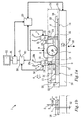
- FIG 1a a device 1 for controlling a tool 2 during machining a work piece 3 by means of the tool 2 is illustrated.
- the tool 2 for machining the work piece 3 is a rotatable side-milling cutter blade arranged to machine grooves 4 in the work piece 3 which in this case is a sheet.
- the tool 2 is usually provided with hard metal inserts for machining a work piece made of metal.
- the tool 2 and the work piece 3 are illustrated in a lateral view. It should be pointed out that although the rotation axis 5 of the tool 2 is substantially horizontal in figures 1a and 1b , the direction of the rotation axis 5 of the tool 2 is not critical to the invention, and for example a vertical rotation axis may also be used.
- the device 1 comprises a first measuring arrangement 6, and as appears from figure 1a in this particular embodiment of the invention the device 1 also comprises a second measuring arrangement 7.
- the first measuring arrangement 6 is arranged ahead of the tool 2, or in other words in front of the tool, with respect to the relative tool movement direction 8.
- the second measuring arrangement 7 is arranged after the tool 2, or in other words behind the tool, with respect to the relative tool movement direction 8.
- Both the first 6 and the second measuring arrangement 7 are moveable relative to the work piece 3 in the relative tool movement direction 8, preferably together with the tool 2.
- This movement of the first and second measuring arrangements 6, 7 may be accomplished by attachment of the first and second measuring arrangement to a unit 9 carrying the tool 2.
- the relative positions of the carrying unit 9 and the first and second measuring arrangements 6, 7 can be fixed.
- a relative movement between the tool 2 and the work piece 3 implies the same relative movement between the first and second measuring arrangements 6, 7 on one hand, and the work piece 3 on the other hand.
- the relative tool movement direction 8 is meant the direction in which the tool 2 is moved relative to the work piece 3 during operation. However, this relative movement may be achieved by moving (to the left in figure 1a ) the unit 9 which carries the tool 2 or by moving the work piece 3 in the opposite direction 8b. Thus, during a milling operation this relative movement between the tool 2 and the work piece 3 is a translation movement. In addition to the translation movement the milling tool 2 is rotated around its rotation axis 5.
- the invention is illustrated when applied during a milling operation, the invention can be applied in connection with other machining operations, such as turning.
- the relative movement and the relative movement direction are then instead determined by the rotation of the work piece relative to the tool.
- the first measuring arrangement 6 comprises a first ultrasonic probe 10 for emitting ultrasonic waves 11.
- the probe functions as a transmitter and a receiver of the waves.
- the expression "ultrasonic waves” used herein comprises sonic waves having a frequency well above 20 kHz, preferably in the interval 1-100 MHz. In many applications a frequency in the interval 5-30 MHz is used, preferably 25 MHz.
- the ultrasonic waves 11 emitted by the first ultrasonic probe 10 are transmitted to the work piece 3 and transmitted back to the first ultrasonic probe 10 by means of a first column of liquid 12.
- the liquid 12 can be water or any other water solution or other liquid suitable for transmitting ultrasonic waves.
- the liquid column has a limited cross section area adapted to the ultrasonic beam, and is surrounded by the atmosphere, usually air.
- This first liquid column 12 can at the same time be used as a cutting fluid for facilitating the machining process and/or cooling the tool 2 and the work piece 3.
- the probe is provided with means for powering the probe, and means for supplying liquid to the probe. These means are schematically illustrated as an electric cable 28a and a water hose 28b, respectively.
- the electric cable can also be used for communication of signals to and from the probe.
- the first measuring arrangement 6 preferably comprises a first nozzle 17 for forming the first column of liquid 12 as a jet directed to the work piece 3.
- the liquid jet direction is preferably substantially perpendicular to the current surface of the work piece to be machined.
- the flow of the jet is preferably substantially a laminar flow.
- the first ultrasonic probe 10 is integrated with the first nozzle 17.
- an emitting unit 18 such as a piezo-electric crystal is arranged to emit the ultrasonic waves.
- the ultrasonic probe and the nozzle are suitably integrated so as to create the jet 12 extending from the emitting unit 18 of the probe to the work piece 3.
- the first nozzle 17 can be arranged at a certain distance 19 from the work piece 3 so as to form a space between the outer end 20 of the first nozzle 17 and the work piece 3 where the jet of liquid is able to flow freely.
- the emitting unit constitutes a combined emitting and receiving unit. However, in another embodiment of the invention both an emitting unit and a separate unit for receiving the reflected ultrasonic waves can be arranged inside the probe.
- the ultrasonic beam gives multiple echoes from the first and second surfaces 13, 14 before being attenuated. One or more of these multiple signals can be used to improve the accuracy of the measurements.
- the second measuring arrangement 7 comprises a second ultrasonic probe 21 for emitting ultrasonic waves 15.
- the probe functions as transmitter and a receiver of the waves.
- the ultrasonic waves emitted by the second ultrasonic probe 21 are transmitted to the work piece 3 and transmitted back to the second ultrasonic probe 21 by means of a second column of liquid 22.
- the probe is provided with means for powering the probe, and means for supplying liquid to the probe.
- the second measuring arrangement 7 preferably comprises a second nozzle 24 for forming the second column of liquid 22 as a jet directed to the work piece 3.
- the second ultrasonic probe 21 is integrated with the second nozzle 24.
- an emitting unit 25 such as a piezo-electric crystal is arranged to emit the ultrasonic waves.
- the ultrasonic probe and the nozzle are suitably integrated so as to create the jet 22 extending from the emitting unit 25 of the probe to the work piece 3.
- the second nozzle 24 can be arranged at a certain distance from the work piece 3 so as to form a space between the outer end 27 of the second nozzle 24 and the work piece 3 where the jet 22 of liquid is able to flow freely.
- the emitting unit constitutes a combined emitting and receiving unit. However, in another embodiment of the invention both an emitting unit and a separate unit for receiving the reflected ultrasonic waves can be arranged inside the probe.
- the ultrasonic beam gives multiple echoes from the machined surface 23 and the second surface 14 before being attenuated. One or more of these multiple signals can be used to improve the accuracy of the measurements.
- the device according to the invention comprises a means 50 for providing signals based on the measurements accomplished by the first ultrasonic probe 10.
- the signals provided are receivable by a control unit 29 for automatically adjusting the position of the tool 2 relative to the work piece during machining the work piece.
- the signal means 50 can be constituted by the piezo-electric crystal 18, which generates an alternating voltage, or by the piezo-electric crystal 18 together with any further conventional equipment arranged inside and/or outside the probe.
- a standard ultrasonic probe which is able to transmit and receive ultrasonic waves and produce an electric signal based on the received waves may be used, provided that the probe fulfils other occurring requirements.
- the signals can be obtained by using such a probe and eventually one or more standard electric components.
- this probe is suitably provided with a means 51 designed to provide signals receivable by the control unit 29 in the same way as the first ultrasonic probe 10.
- the device 1 comprises an ultrasonic system 60 which communicates with the first 10 and second 21 probes. From the ultrasonic system 60 the probes are fed with pulses and signals received by the probes are transferred back to the ultrasonic system.
- the ultrasonic system 60 suitably comprises the above-mentioned components as amplifiers, filters and/or A/D converters for processing the signals.
- a computer unit 61 provided with a monitor 62 is used to run the ultrasonic system 60 by executing a computer program.
- the computer unit 61 can also be used for storing and/or displaying the measured distances to the work piece and/or the measured wall thicknesses of the work piece.
- the computer unit 61 is connected to the control unit 29 of the milling machine so as to provide control signals for adjusting the tool position.
- the computer program may comprise an instruction set stored in an internal memory of the computer to instruct a processor for accomplishing the steps of the method when the instruction set is executed in the computer.
- the computer program can be provided at least partly via a network such as the Internet.
- the computer may be designed for receiving a computer readable medium having a stored program or data thereon intended to cause the computer to control the steps of the method according to the invention.
- the measurements which can be accomplished by the first and second ultrasonic probes can be divided into distance measurements and thickness measurements.
- the distance 30 between the first ultrasonic probe 10 and the first surface 13 of the work piece 3 can be calculated.
- Knowledge about the distance 30 from the first ultrasonic probe 10 to the first surface 13 of the work piece makes it possible to calculate the position of the tool 2 relative to the work piece 3, since the distance 31 from the first ultrasonic probe 10 to the tool is predetermined.
- the distance between the first surface 13 and the second surface 14, i.e. the thickness 33 of the work piece 3 can be calculated.
- the first echo received by the second ultrasonic probe 21 gives information about the distance 34 between the second ultrasonic probe 21 and the machined surface 23 of the work piece 3.
- Knowledge about the distance 34 from the second ultrasonic probe 21 to the machined surface 23 of the work piece 3, together with information about the original thickness 33 of the work piece or the distance 32 to the second surface 14 makes it possible to calculate the current thickness 35 of the work piece.
- Using information about the original distance 30 to the first surface 13 and the distance to the machined surface 23 makes it possible to calculate the real cutting depth 36.
- the distance between the machined surface 23 and the second surface 14, i.e. thickness 35 of the of the work piece can be calculated.
- the control unit 29 receiving signals from the computer unit 61 is in turn able to emit signals to the milling machine to control the movement of the tool carrying unit 9 and/or the sliding carriage 16 supporting the work piece 3.
- the relative movement may be achieved by moving the work piece 3 or moving the tool 2.
- the milling machine can be a so called NC or CNC milling machine.
- the tool 2 and the work piece 3 can be brought towards each other or away from each other in the vertical direction 26 by controlling a motor (not shown) driving the sliding carriage 16.
- the position of the tool 2 relative to the work piece 3 is adjusted based only on the calculated distance from the first ultrasonic probe 10 to the first surface.
- the position of the tool 2 relative to the work piece 3 is adjusted based only on the calculated thickness 33 of the work piece 3 between the first surface 13 and a second surface 14 of the work piece 3.
- the position of the tool 2 relative to the work piece 3 is adjusted based on both the calculated distance from the first ultrasonic probe 10 to the first surface and on the calculated thickness 33 of the work piece 3 between the first surface 13 and a second surface 14 of the work piece 3.
- a step ie when the position of the tool 2 relative to the work piece 3 is adjusted based only on the calculated thickness 33 of the work piece 3 between the first surface 13 and a second surface 14 of the work piece 3, a multitude of steps are performed; a) the tool 2 is brought into contact with the work piece before the machining operation is initiated, b) a wall thickness is calculated at the point of contact, and c) the tool is controlled to a nominal engagement depth based on the calculated wall thickness so that the wall thickness of the meachined portion of the work piece 3 is not less than a tolerance requirement.
- a focused beam of ultrasonic waves is very usable. This is particularly the case when machining narrow grooves and/or machining a work piece having a curved surface.
- the ultrasonic waves can be directed into the groove without being disturbed by the surface close to the groove or by the edges of the walls defining the groove.
- the beam can be directed into the groove and substantially the entire cross section of the beam can reach the bottom of the groove so as to measure the wall thickness of the work piece between the machined bottom surface 23 of the groove and the second surface 14.
- a focused beam concentrates the measurement on a limited and well defined area of the work piece.
- the focal distance is the distance between the emitting unit and the position at the ultrasonic beam where the beam is focused to a focal diameter
- the focal length is the extension of the ultrasonic beam having an appropriate focal diameter
- the diameter of the ultrasonic beam is the extension of the beam in a cross section of the ultrasonic beam.
- the focal diameter is normally allowed to vary within a certain interval.
- a probe with an emitting unit 18, and an ultrasonic beam 11 and a jet of liquid 12 are schematically illustrated.
- the liquid jet may have an extension 30 from the emitting unit 18 to the work piece 3 in the interval 5-150 mm, and preferably 10-100 mm.
- the illustrated liquid jet 12 has a larger diameter D than the beam 11, the liquid jet diameter D as well as the beam diameter d can be different for other applications, and for example, the liquid jet and the beam could have substantially the same cross section diameter. Both the liquid diameter and the beam diameter are preferably adapted to the shape of the work piece. In the case of a substantially plane surface as illustrated in figure 2a the diameters are not so critical, provided that the jet diameter D is at least equal to the beam diameter d such that sufficient echoes of the ultrasonic waves are obtained.
- the first ultrasonic probe 10 emits an unfocused beam of ultrasonic waves.
- the extension of the beam perpendicular to its longitudinal direction is substantially constant, or somewhat diverging.
- a more complicated geometry of the work piece 3, such as grooves 4 cut into the surface means that the jet diameter D and/or the beam diameter d have to be adapted to the dimensions of the work piece 3.
- the ultrasonic beam 15 is focused so as to obtain a smaller focal diameter d f adapted to the width 52 and the depth 36 of the groove 4.
- the entire cross section of the beam hits the bottom surface 23 of the groove 4.
- the focal diameter d f is often in the interval 0,1-2 mm, preferably 0,3-1,5 mm, and more preferably 0,4-1 mm.
- the focal point is situated ahead of the outlet 27 of the nozzle 24, and preferably the focal point is situated 1-10 mm ahead of the outlet 27 of the nozzle 24.
- the jet diameter D is preferably at least 2 times the width 52 of the current groove 4.
- the jet is centred relative to the groove 4.
- the laminar flow of the jet is not much disturbed by the surrounding portions of the work piece 3.
- a laminar flow and a minimum of disturbances of the flow when hitting the surface promote a favourable propagation of the ultrasonic waves.
- Such a liquid jet 22 has often a diameter close to the work piece in the interval 5 to 20 mm.
- the diameter D corresponds substantially to the extension of the width of one groove 4 and two ridges 53 situated adjacent to the groove.
- the liquid jet is convergent.
- the nozzle 24 has a conical channel 54 for forming the jet of liquid.
- This means the jet of liquid is convergent inside the nozzle 24 in the direction from the emitting unit 25 towards the mouth 27 of the nozzle.
- the jet can be adapted to the shape of the work piece.
- the size of the jet diameter can be adapted to the size of a groove into which the jet is directed. This can counteract disturbance of the jet.
- the cross section diameter of the jet close to the work piece is often in the interval 0,2 to 1 mm when using a convergent ultrasonic beam.
- the first ultrasonic probe 10 emits a focused beam of ultrasonic waves.
- the beam diameter of such a focused beam is preferably controlled to a value corresponding to, ie the same as or close to, the width of the machining tool. In this way, an accurate measurement of exactly the work piece area to be machined by the tool may be measured. Thus, the distance to the work piece 3 and/or thickness of the work piece may be calculated accurately.
Landscapes
- Physics & Mathematics (AREA)
- General Physics & Mathematics (AREA)
- Biochemistry (AREA)
- General Health & Medical Sciences (AREA)
- Health & Medical Sciences (AREA)
- Life Sciences & Earth Sciences (AREA)
- Chemical & Material Sciences (AREA)
- Analytical Chemistry (AREA)
- Engineering & Computer Science (AREA)
- Pathology (AREA)
- Mechanical Engineering (AREA)
- Immunology (AREA)
- Acoustics & Sound (AREA)
- Length Measuring Devices Characterised By Use Of Acoustic Means (AREA)
- Automatic Control Of Machine Tools (AREA)
- Surgical Instruments (AREA)
Claims (14)
- Verfahren zur Steuerung eines Werkzeugs (2) während einer Bearbeitung eines Werkstücks (3) mittels des Werkzeugs (2), das den Schritt der Verwendung einer ersten Messanordnung (6) mit einer ersten Ultraschallsonde (10) für eine Emittierung von Ultraschallwellen umfasst, dadurch gekennzeichnet, dass die erste Messanordnung (6) bezüglich der relativen Werkzeugbewegungsrichtung (8) vor dem Werkzeug (2) angeordnet ist und bezüglich des Werkstücks (3) in der relativen Werkzeugbewegungsrichtung (8) bewegt wird, wobei die durch die erste Ultraschallsonde (10) emittierten Ultraschallwellen zu dem Werkstück (3) und zurück zu der ersten Ultraschallsonde (10) mittels einer ersten Flüssigkeitssäule (12) übertragen werden, die durch die erste Messanordnung (6) erzeugt wird und sich zwischen der ersten Ultraschallsonde (10) und dem Werkstück (3) zur Messung befindet, und die Messung zur automatischen Einstellung der Position des Werkzeugs (2) bezüglich des Werkstücks (3) während der Bearbeitung des Werkstücks (3) und der Übertragung der durch die erste Ultraschallsonde (10) zu der ersten Oberfläche (13) emittierten Ultraschallwellen verwendet wird, wobei sich die erste Flüssigkeitssäule (12) zur Messung des Abstands (30) von der ersten Ultraschallsonde (10) zu der ersten Oberfläche (13) zwischen der Ultraschallsonde (10) und der ersten Oberfläche (13) befindet, und die Abstandsmessungen für eine automatische Einstellung der Position des Werkzeugs (2) bezüglich des Werkstücks (3) während der Bearbeitung des Werkstücks (3) verwendet werden.
- Verfahren nach Anspruch 1 oder 2, dadurch gekennzeichnet, dass die erste Ultraschallsonde (10) zur Messung der Dicke (33) des Werkstücks (3) zwischen der ersten Oberfläche (13) und einer zweiten Oberfläche (14) des Werkstücks (3) verwendet wird, und dass die Dickenmessungen für eine automatische Einstellung der Position des Werkzeugs (2) bezüglich des Werkstücks (3) während der Bearbeitung des Werkstücks (3) verwendet werden.
- Verfahren nach einem vorhergehenden Anspruch, dadurch gekennzeichnet, dass eine zweite Messanordnung (7) mit einer zweiten Ultraschallsonde (21) für eine Emittierung von Ultraschallwellen verwendet wird, wobei die zweite Messanordnung (7) nach dem Werkzeug (2) bezüglich der relativen Werkzeugbewegungsrichtung (8) angeordnet ist und bezüglich des Werkzeugs (3) in der relativen Werkzeugbewegungsrichtung (8) bewegt wird, wobei die durch die zweite Ultraschallsonde (21) emittierten Ultraschallwellen zu einer Oberfläche (23) des Werkstücks (3), die durch das Werkzeug (2) bearbeitet wurde, und zu der zweiten Ultraschallsonde (21) zurück mittels einer zweiten Flüssigkeitssäule (22) übertragen werden, die durch die zweite Messanordnung (7) erzeugt wird und sich zwischen der zweiten Ultraschallsonde (21) und der bearbeiteten Oberfläche (23) befindet, und die durch die zweite Ultraschallsonde (21) durchgeführten Messungen für eine automatische Einstellung der Position des Werkzeugs (2) bezüglich des Werkstücks (3) während der Bearbeitung des Werkstücks (3) verwendet werden.
- Verfahren nach Anspruch 4, dadurch gekennzeichnet, dass die zweite Ultraschallsonde (21) für eine Messung der Dicke (35) des Werkstücks (3) zwischen der bearbeiteten Oberfläche (23) und der zweiten Oberfläche (14) verwendet wird.
- Verfahren nach Anspruch 4 oder 5, dadurch gekennzeichnet, dass die zweite Ultraschallsonde (21) für eine Messung des Abstands (34) von der zweiten Ultraschallsonde (21) zu der bearbeiteten Oberfläche (23) verwendet wird und die Dicke (35) des Werkstücks (3) zwischen der bearbeiteten Oberfläche (23) und der zweiten Oberfläche (14) mittels des gemessenen Abstands (34) berechnet wird.
- Verfahren nach Anspruch 5, dadurch gekennzeichnet, dass die Dicke (35) zwischen der bearbeiteten Oberfläche (23) und der zweiten Oberfläche (14) des Werkstücks (3) aufgezeichnet wird.
- Verfahren nach einem vorhergehenden Anspruch, dadurch gekennzeichnet, dass eine erste Düse (17) zur Bildung der ersten Flüssigkeitssäule (12) in Form eines auf das Werkstück (3) gerichteten Strahls verwendet wird.
- Verfahren nach Anspruch 8, dadurch gekennzeichnet, dass die erste Düse (17) in einem bestimmten Abstand (19) von dem Werkstück (3) angeordnet wird, um einen Raum zwischen der ersten Düse (17) und dem Werkstück (3) zu bilden, in dem der Flüssigkeitsstrahl frei strömen kann.
- Vorrichtung zur Steuerung eines Werkzeugs (2) während einer Bearbeitung eines Werkstücks (3) mittels des Werkzeugs, wobei die Vorrichtung eine erste Messanordnung (6) mit einer ersten Ultraschallsonde (10) für eine Emittierung von Ultraschallwellen umfasst, dadurch gekennzeichnet, dass die erste Messanordnung (6) so ausgelegt ist, dass sie vor dem Werkzeug (2) bezüglich der relativen Werkzeugbewegungsrichtung (8) angeordnet wird und in der relativen Werkzeugbewegungsrichtung (8) bewegt wird, wobei die erste Messanordnung eine erste Düse (17) zur Erzeugung einer ersten Flüssigkeitssäule (12) zwischen der ersten Ultraschallsonde (10) und dem Werkstück (3) für eine Übertragung der Ultraschallwellen von der ersten Ultraschallsonde (10) zu dem Werkstück (3) und der reflektierten Ultraschallwellen von dem Werkstück (3) zu der ersten Ultraschallsonde (10) und eine Einrichtung (50) zur Schaffung von Signalen auf Basis der durch die erste Ultraschallsonde (10) durchgeführten Messungen aufweist, wobei die Signale durch eine Steuereinheit (29) für eine automatische Einstellung der Position des Werkzeugs (2) bezüglich des Werkstücks (3) während einer Bearbeitung des Werkstücks (3) empfangbar sind, und dass die erste Ultraschallsonde (10) so konfiguriert ist, dass sie die Ultraschallwellen zu einer erste Oberfläche (13) des Werkstücks (3) überträgt, wobei die erste Flüssigkeitssäule (12) sich zwischen der ersten Ultraschallsonde (10) und der ersten Oberfläche (13) zur Messung des Abstands (30) von der ersten Ultraschallsonde (10) zur ersten Oberfläche (13) befindet und die Abstandsmessungen für eine automatische Einstellung der Position des Werkzeugs (2) bezüglich des Werkstücks (3) während der Bearbeitung des Werkstücks (3) verwendet werden.
- Vorrichtung nach Anspruch 9, dadurch gekennzeichnet, dass die Vorrichtung eine zweite Messanordnung (7) umfasst, die eine zweite Ultraschallsonde (21) zur Emittierung von Ultraschallwellen aufweist, wobei die zweite Messanordnung (7) so ausgelegt ist, dass sie nach dem Werkzeug (2) bezüglich der relativen Werkzeugbewegungsrichtung (8) angeordnet wird und in der relativen Werkzeugbewegungsrichtung (8) bewegt wird, wobei die zweite Messanordnung (7) eine zweite Düse (24) zur Erzeugung einer zweiten Flüssigkeitssäule (22) zwischen der zweiten Ultraschallsonde (21) und einer Oberfläche (23) des Werkstücks (3) aufweist, die von dem Werkzeug bearbeitet wird, um Ultraschallwellen von der zweiten Ultraschallsonde (21) zu der bearbeiteten Oberfläche (23) und reflektierte Ultraschallwellen von dem Werkstück (3) zu der zweiten Ultraschallsonde (21) zu übertragen, und eine Einrichtung (51) zur Schaffung von Signalen auf der Basis der durch die zweite Ultraschallsonde (21) durchgeführten Messungen aufweist, wobei die Signale von einer Steuereinheit (29) für eine automatische Einstellung des Werkzeugs (2) bezüglich des Werkstücks (3) während der Bearbeitung des Werkstücks (3) empfangbar sind.
- Fräsmaschine mit einer Vorrichtung nach Anspruch 9 oder 10.
- Computerprogramm mit Softwarecodeteilen für eine Instruierung eines Prozessors zur Durchführung der Schritte nach einem der Ansprüche 1 - 8, wenn das Programm in einem Computer ausgeführt wird.
- Computerprogramm nach Anspruch 12, das wenigstens teilweise über ein Netzwerk, wie z.B. das Internet, bereitgestellt wird.
- Computerlesbares Medium mit einem darauf gespeicherten Programm, das dazu dient, dass ein Computer die Schritte nach einem der Ansprüche 1 - 8 steuert.
Applications Claiming Priority (1)
| Application Number | Priority Date | Filing Date | Title |
|---|---|---|---|
| PCT/SE2005/001588 WO2007046737A1 (en) | 2005-10-21 | 2005-10-21 | A method and device for controlling a tool with ultrasonic waves |
Publications (2)
| Publication Number | Publication Date |
|---|---|
| EP1940586A1 EP1940586A1 (de) | 2008-07-09 |
| EP1940586B1 true EP1940586B1 (de) | 2011-02-09 |
Family
ID=37962750
Family Applications (1)
| Application Number | Title | Priority Date | Filing Date |
|---|---|---|---|
| EP05796409A Expired - Lifetime EP1940586B1 (de) | 2005-10-21 | 2005-10-21 | Verfahren und vorrichtung zur steuerung eines werkzeugs mit ultraschallwellen |
Country Status (5)
| Country | Link |
|---|---|
| US (1) | US8419324B2 (de) |
| EP (1) | EP1940586B1 (de) |
| AT (1) | ATE497859T1 (de) |
| DE (1) | DE602005026340D1 (de) |
| WO (1) | WO2007046737A1 (de) |
Families Citing this family (8)
| Publication number | Priority date | Publication date | Assignee | Title |
|---|---|---|---|---|
| US20130195573A1 (en) * | 2010-10-14 | 2013-08-01 | Christian Podiebrad | Machine tool comprising an ultrasonic sensor |
| GB2540374A (en) * | 2015-07-14 | 2017-01-18 | Airbus Operations Ltd | Machine tool control & measurement system |
| KR101736612B1 (ko) * | 2015-12-07 | 2017-05-17 | 주식회사 포스코 | 높이 조절형 초음파 센서를 이용한 강판의 내부 결함 탐상 장치 및 방법 |
| WO2017203068A1 (es) * | 2016-05-25 | 2017-11-30 | Zayer, S.A. | Cabezal de máquina herramienta con dispositivo de medida |
| JP6174208B2 (ja) * | 2016-08-04 | 2017-08-02 | 加賀産業株式会社 | シム製作方法 |
| JP7383346B2 (ja) * | 2020-01-24 | 2023-11-20 | 株式会社ディスコ | 測定方法 |
| US11969947B2 (en) * | 2020-11-06 | 2024-04-30 | Abb Schweiz Ag | Technologies for non-contact displacement control |
| CN116748666A (zh) * | 2023-07-25 | 2023-09-15 | 北京航空航天大学 | 一种超声辅助激光湿法加工系统及方法 |
Family Cites Families (16)
| Publication number | Priority date | Publication date | Assignee | Title |
|---|---|---|---|---|
| US3483795A (en) * | 1967-06-09 | 1969-12-16 | North American Rockwell | Closed loop feedback for machining |
| US3834256A (en) * | 1973-08-15 | 1974-09-10 | Atomic Energy Commission | Ultrasonically controlled thickness machining |
| US3935766A (en) * | 1973-10-09 | 1976-02-03 | Masters Christopher F | Method and apparatus for machining cylindrical tubes |
| FR2287679A1 (fr) | 1974-10-09 | 1976-05-07 | Aerospatiale | Dispositif de mesure continue de l'epaisseur d'une piece en cours d'usinage |
| US4026143A (en) * | 1976-02-23 | 1977-05-31 | General Dynamics Corporation | Ultrasonic sensor assembly |
| EP0038055A3 (de) * | 1980-04-16 | 1982-08-18 | Georg Fischer Aktiengesellschaft | Ultraschallprüfverfahren |
| US4620281A (en) * | 1981-09-22 | 1986-10-28 | General Electric Company | In-process cutting tool condition compensation and part inspection |
| DE3203862C2 (de) * | 1982-02-05 | 1983-12-22 | Messerschmitt-Bölkow-Blohm GmbH, 8000 München | Ultraschall-Prüfkopfanordnung zur zerstörungsfreien Ultraschallprüfung |
| FR2581334B1 (fr) * | 1985-05-06 | 1987-12-31 | Electricite De France | Procede et installation d'usinage d'une piece creuse par fraisage le long d'un trace predetermine |
| DE3637236A1 (de) * | 1986-11-03 | 1988-05-19 | Stabil Elektronik Gmbh | Steuerungs- und ueberwachungsanordnung fuer ein werkzeug |
| CS270004B1 (en) | 1987-12-12 | 1990-06-13 | Valenta Jiri | Method of cutting process trajectory adaptive control and device for realization of this method |
| JPH0655414A (ja) | 1992-08-13 | 1994-03-01 | Mechatro Tokiwa Internatl:Kk | 超音波による工具位置の測定方法 |
| US5747693A (en) * | 1992-11-06 | 1998-05-05 | The United States Of America As Represented By The Secretary Of The Army | System for taking transverse measurements |
| KR960013170B1 (ko) * | 1992-12-03 | 1996-09-30 | 미쯔시다덴기산교 가부시기가이샤 | 바이트이동식 절삭장치 |
| US5948985A (en) * | 1996-05-31 | 1999-09-07 | Ormet Corporation | Method and apparatus for ultrasonic testing of aluminum billet |
| US5850184A (en) * | 1997-06-25 | 1998-12-15 | Cobra Machine Tool Co., Inc. | Ultrasonic tool confirmation sensor |
-
2005
- 2005-10-21 WO PCT/SE2005/001588 patent/WO2007046737A1/en not_active Ceased
- 2005-10-21 DE DE602005026340T patent/DE602005026340D1/de not_active Expired - Lifetime
- 2005-10-21 US US12/089,185 patent/US8419324B2/en active Active
- 2005-10-21 AT AT05796409T patent/ATE497859T1/de not_active IP Right Cessation
- 2005-10-21 EP EP05796409A patent/EP1940586B1/de not_active Expired - Lifetime
Also Published As
| Publication number | Publication date |
|---|---|
| US20080260482A1 (en) | 2008-10-23 |
| EP1940586A1 (de) | 2008-07-09 |
| DE602005026340D1 (de) | 2011-03-24 |
| ATE497859T1 (de) | 2011-02-15 |
| WO2007046737A1 (en) | 2007-04-26 |
| US8419324B2 (en) | 2013-04-16 |
Similar Documents
| Publication | Publication Date | Title |
|---|---|---|
| US10684261B2 (en) | Ultrasonic bar and tube end testing with linear axis robot | |
| EP2053391B1 (de) | Vorrichtung und Verfahren zur nichtzerstörenden Überprüfung von Teilen | |
| US6021682A (en) | Automatic machinability measuring and machining methods and apparatus therefor | |
| US4118139A (en) | Machine tool and method | |
| CN103547404B (zh) | 用于扫描待在激光切割机上进行加工的管的方法 | |
| EP1940586B1 (de) | Verfahren und vorrichtung zur steuerung eines werkzeugs mit ultraschallwellen | |
| EP3266563B1 (de) | Kombinierte numerische computersteuerungsverarbeitungsmaschine und verarbeitungsverfahren dafür | |
| US20130195573A1 (en) | Machine tool comprising an ultrasonic sensor | |
| Vasilev et al. | Feed forward control of welding process parameters through on-line ultrasonic thickness measurement | |
| CN114406449A (zh) | 一种水导激光打孔复合钻削装置及方法 | |
| US3483795A (en) | Closed loop feedback for machining | |
| JPH08504133A (ja) | 中空ワークピースのキャビティの平均的軸線と回転機器の回転軸との心合わせ方法 | |
| EP3465196B1 (de) | Verfahren zur ultraschallprüfung von länglichen hohlprofilen | |
| JP6837361B2 (ja) | 溶接部位置検知装置、超音波探傷装置、溶接部探傷方法および溶接部位置検知プログラム | |
| JPH06328349A (ja) | インライン切削肌粗さ測定方法 | |
| US20100007871A1 (en) | Method and device for locating a piece with respect to a tool | |
| Liu et al. | Industrial robot-based system design of thickness scanning measurement using ultrasonic | |
| Shawky et al. | In-process monitoring and control of thickness error in machining hollow shafts | |
| Deutsch et al. | Automated ultrasonic pipe weld inspection | |
| Wang et al. | On-machine ultrasonic thickness measurement and compensation of thin-walled parts machining on a CNC lathe | |
| JP2007090412A (ja) | 精密加工機 | |
| JPH0655414A (ja) | 超音波による工具位置の測定方法 | |
| Deutsch et al. | Automatic inspection of welded pipes with ultrasound | |
| CN220161529U (zh) | 一种高精密u轴微调机构 | |
| Cerwenka et al. | Development of a flexible low laser power hybrid (LLPH) technology for shipbuilding including additive manufacturedsemi-automated hand-held unit |
Legal Events
| Date | Code | Title | Description |
|---|---|---|---|
| PUAI | Public reference made under article 153(3) epc to a published international application that has entered the european phase |
Free format text: ORIGINAL CODE: 0009012 |
|
| 17P | Request for examination filed |
Effective date: 20080521 |
|
| AK | Designated contracting states |
Kind code of ref document: A1 Designated state(s): AT BE BG CH CY CZ DE DK EE ES FI FR GB GR HU IE IS IT LI LT LU LV MC NL PL PT RO SE SI SK TR |
|
| 17Q | First examination report despatched |
Effective date: 20091014 |
|
| GRAP | Despatch of communication of intention to grant a patent |
Free format text: ORIGINAL CODE: EPIDOSNIGR1 |
|
| GRAS | Grant fee paid |
Free format text: ORIGINAL CODE: EPIDOSNIGR3 |
|
| GRAA | (expected) grant |
Free format text: ORIGINAL CODE: 0009210 |
|
| AK | Designated contracting states |
Kind code of ref document: B1 Designated state(s): AT BE BG CH CY CZ DE DK EE ES FI FR GB GR HU IE IS IT LI LT LU LV MC NL PL PT RO SE SI SK TR |
|
| REG | Reference to a national code |
Ref country code: GB Ref legal event code: FG4D |
|
| REG | Reference to a national code |
Ref country code: CH Ref legal event code: EP |
|
| REG | Reference to a national code |
Ref country code: IE Ref legal event code: FG4D |
|
| REF | Corresponds to: |
Ref document number: 602005026340 Country of ref document: DE Date of ref document: 20110324 Kind code of ref document: P |
|
| REG | Reference to a national code |
Ref country code: DE Ref legal event code: R096 Ref document number: 602005026340 Country of ref document: DE Effective date: 20110324 |
|
| REG | Reference to a national code |
Ref country code: NL Ref legal event code: VDEP Effective date: 20110209 |
|
| LTIE | Lt: invalidation of european patent or patent extension |
Effective date: 20110209 |
|
| PG25 | Lapsed in a contracting state [announced via postgrant information from national office to epo] |
Ref country code: PT Free format text: LAPSE BECAUSE OF FAILURE TO SUBMIT A TRANSLATION OF THE DESCRIPTION OR TO PAY THE FEE WITHIN THE PRESCRIBED TIME-LIMIT Effective date: 20110609 Ref country code: LV Free format text: LAPSE BECAUSE OF FAILURE TO SUBMIT A TRANSLATION OF THE DESCRIPTION OR TO PAY THE FEE WITHIN THE PRESCRIBED TIME-LIMIT Effective date: 20110209 Ref country code: SE Free format text: LAPSE BECAUSE OF FAILURE TO SUBMIT A TRANSLATION OF THE DESCRIPTION OR TO PAY THE FEE WITHIN THE PRESCRIBED TIME-LIMIT Effective date: 20110209 Ref country code: ES Free format text: LAPSE BECAUSE OF FAILURE TO SUBMIT A TRANSLATION OF THE DESCRIPTION OR TO PAY THE FEE WITHIN THE PRESCRIBED TIME-LIMIT Effective date: 20110520 Ref country code: LT Free format text: LAPSE BECAUSE OF FAILURE TO SUBMIT A TRANSLATION OF THE DESCRIPTION OR TO PAY THE FEE WITHIN THE PRESCRIBED TIME-LIMIT Effective date: 20110209 Ref country code: GR Free format text: LAPSE BECAUSE OF FAILURE TO SUBMIT A TRANSLATION OF THE DESCRIPTION OR TO PAY THE FEE WITHIN THE PRESCRIBED TIME-LIMIT Effective date: 20110510 |
|
| PG25 | Lapsed in a contracting state [announced via postgrant information from national office to epo] |
Ref country code: CY Free format text: LAPSE BECAUSE OF FAILURE TO SUBMIT A TRANSLATION OF THE DESCRIPTION OR TO PAY THE FEE WITHIN THE PRESCRIBED TIME-LIMIT Effective date: 20110209 Ref country code: BE Free format text: LAPSE BECAUSE OF FAILURE TO SUBMIT A TRANSLATION OF THE DESCRIPTION OR TO PAY THE FEE WITHIN THE PRESCRIBED TIME-LIMIT Effective date: 20110209 Ref country code: SI Free format text: LAPSE BECAUSE OF FAILURE TO SUBMIT A TRANSLATION OF THE DESCRIPTION OR TO PAY THE FEE WITHIN THE PRESCRIBED TIME-LIMIT Effective date: 20110209 Ref country code: PL Free format text: LAPSE BECAUSE OF FAILURE TO SUBMIT A TRANSLATION OF THE DESCRIPTION OR TO PAY THE FEE WITHIN THE PRESCRIBED TIME-LIMIT Effective date: 20110209 Ref country code: AT Free format text: LAPSE BECAUSE OF FAILURE TO SUBMIT A TRANSLATION OF THE DESCRIPTION OR TO PAY THE FEE WITHIN THE PRESCRIBED TIME-LIMIT Effective date: 20110209 Ref country code: FI Free format text: LAPSE BECAUSE OF FAILURE TO SUBMIT A TRANSLATION OF THE DESCRIPTION OR TO PAY THE FEE WITHIN THE PRESCRIBED TIME-LIMIT Effective date: 20110209 Ref country code: NL Free format text: LAPSE BECAUSE OF FAILURE TO SUBMIT A TRANSLATION OF THE DESCRIPTION OR TO PAY THE FEE WITHIN THE PRESCRIBED TIME-LIMIT Effective date: 20110209 Ref country code: BG Free format text: LAPSE BECAUSE OF FAILURE TO SUBMIT A TRANSLATION OF THE DESCRIPTION OR TO PAY THE FEE WITHIN THE PRESCRIBED TIME-LIMIT Effective date: 20110509 |
|
| PG25 | Lapsed in a contracting state [announced via postgrant information from national office to epo] |
Ref country code: DK Free format text: LAPSE BECAUSE OF FAILURE TO SUBMIT A TRANSLATION OF THE DESCRIPTION OR TO PAY THE FEE WITHIN THE PRESCRIBED TIME-LIMIT Effective date: 20110209 Ref country code: EE Free format text: LAPSE BECAUSE OF FAILURE TO SUBMIT A TRANSLATION OF THE DESCRIPTION OR TO PAY THE FEE WITHIN THE PRESCRIBED TIME-LIMIT Effective date: 20110209 |
|
| PG25 | Lapsed in a contracting state [announced via postgrant information from national office to epo] |
Ref country code: CZ Free format text: LAPSE BECAUSE OF FAILURE TO SUBMIT A TRANSLATION OF THE DESCRIPTION OR TO PAY THE FEE WITHIN THE PRESCRIBED TIME-LIMIT Effective date: 20110209 Ref country code: SK Free format text: LAPSE BECAUSE OF FAILURE TO SUBMIT A TRANSLATION OF THE DESCRIPTION OR TO PAY THE FEE WITHIN THE PRESCRIBED TIME-LIMIT Effective date: 20110209 Ref country code: RO Free format text: LAPSE BECAUSE OF FAILURE TO SUBMIT A TRANSLATION OF THE DESCRIPTION OR TO PAY THE FEE WITHIN THE PRESCRIBED TIME-LIMIT Effective date: 20110209 |
|
| PLBE | No opposition filed within time limit |
Free format text: ORIGINAL CODE: 0009261 |
|
| STAA | Information on the status of an ep patent application or granted ep patent |
Free format text: STATUS: NO OPPOSITION FILED WITHIN TIME LIMIT |
|
| 26N | No opposition filed |
Effective date: 20111110 |
|
| REG | Reference to a national code |
Ref country code: DE Ref legal event code: R097 Ref document number: 602005026340 Country of ref document: DE Effective date: 20111110 |
|
| PG25 | Lapsed in a contracting state [announced via postgrant information from national office to epo] |
Ref country code: MC Free format text: LAPSE BECAUSE OF NON-PAYMENT OF DUE FEES Effective date: 20111031 |
|
| REG | Reference to a national code |
Ref country code: CH Ref legal event code: PL |
|
| GBPC | Gb: european patent ceased through non-payment of renewal fee |
Effective date: 20111021 |
|
| PG25 | Lapsed in a contracting state [announced via postgrant information from national office to epo] |
Ref country code: LI Free format text: LAPSE BECAUSE OF NON-PAYMENT OF DUE FEES Effective date: 20111031 Ref country code: CH Free format text: LAPSE BECAUSE OF NON-PAYMENT OF DUE FEES Effective date: 20111031 |
|
| REG | Reference to a national code |
Ref country code: IE Ref legal event code: MM4A |
|
| PG25 | Lapsed in a contracting state [announced via postgrant information from national office to epo] |
Ref country code: GB Free format text: LAPSE BECAUSE OF NON-PAYMENT OF DUE FEES Effective date: 20111021 |
|
| PG25 | Lapsed in a contracting state [announced via postgrant information from national office to epo] |
Ref country code: IE Free format text: LAPSE BECAUSE OF NON-PAYMENT OF DUE FEES Effective date: 20111021 |
|
| PG25 | Lapsed in a contracting state [announced via postgrant information from national office to epo] |
Ref country code: LU Free format text: LAPSE BECAUSE OF NON-PAYMENT OF DUE FEES Effective date: 20111021 |
|
| PG25 | Lapsed in a contracting state [announced via postgrant information from national office to epo] |
Ref country code: IS Free format text: LAPSE BECAUSE OF FAILURE TO SUBMIT A TRANSLATION OF THE DESCRIPTION OR TO PAY THE FEE WITHIN THE PRESCRIBED TIME-LIMIT Effective date: 20110209 |
|
| PG25 | Lapsed in a contracting state [announced via postgrant information from national office to epo] |
Ref country code: TR Free format text: LAPSE BECAUSE OF FAILURE TO SUBMIT A TRANSLATION OF THE DESCRIPTION OR TO PAY THE FEE WITHIN THE PRESCRIBED TIME-LIMIT Effective date: 20110209 |
|
| PG25 | Lapsed in a contracting state [announced via postgrant information from national office to epo] |
Ref country code: HU Free format text: LAPSE BECAUSE OF FAILURE TO SUBMIT A TRANSLATION OF THE DESCRIPTION OR TO PAY THE FEE WITHIN THE PRESCRIBED TIME-LIMIT Effective date: 20110209 |
|
| REG | Reference to a national code |
Ref country code: DE Ref legal event code: R082 Ref document number: 602005026340 Country of ref document: DE Representative=s name: D YOUNG & CO LLP, GB |
|
| REG | Reference to a national code |
Ref country code: FR Ref legal event code: PLFP Year of fee payment: 12 |
|
| PGFP | Annual fee paid to national office [announced via postgrant information from national office to epo] |
Ref country code: IT Payment date: 20161024 Year of fee payment: 12 |
|
| REG | Reference to a national code |
Ref country code: DE Ref legal event code: R082 Ref document number: 602005026340 Country of ref document: DE Representative=s name: D YOUNG & CO LLP, DE Ref country code: DE Ref legal event code: R082 Ref document number: 602005026340 Country of ref document: DE Representative=s name: D YOUNG & CO LLP, GB Ref country code: DE Ref legal event code: R081 Ref document number: 602005026340 Country of ref document: DE Owner name: GKN AEROSPACE SWEDEN AB, SE Free format text: FORMER OWNER: VOLVO AERO CORP., TROLLHAETTAN, SE |
|
| REG | Reference to a national code |
Ref country code: FR Ref legal event code: PLFP Year of fee payment: 13 |
|
| REG | Reference to a national code |
Ref country code: FR Ref legal event code: CD Owner name: GKN AEROSPACE SWEDEN AB, SE Effective date: 20171226 |
|
| REG | Reference to a national code |
Ref country code: FR Ref legal event code: PLFP Year of fee payment: 14 |
|
| PG25 | Lapsed in a contracting state [announced via postgrant information from national office to epo] |
Ref country code: IT Free format text: LAPSE BECAUSE OF NON-PAYMENT OF DUE FEES Effective date: 20171021 |
|
| REG | Reference to a national code |
Ref country code: DE Ref legal event code: R082 Ref document number: 602005026340 Country of ref document: DE Representative=s name: D YOUNG & CO LLP, DE |
|
| P01 | Opt-out of the competence of the unified patent court (upc) registered |
Effective date: 20230526 |
|
| PGFP | Annual fee paid to national office [announced via postgrant information from national office to epo] |
Ref country code: FR Payment date: 20240909 Year of fee payment: 20 |
|
| PGFP | Annual fee paid to national office [announced via postgrant information from national office to epo] |
Ref country code: DE Payment date: 20240904 Year of fee payment: 20 |
|
| REG | Reference to a national code |
Ref country code: DE Ref legal event code: R071 Ref document number: 602005026340 Country of ref document: DE |