EP1939992A2 - Jack - Google Patents
Jack Download PDFInfo
- Publication number
- EP1939992A2 EP1939992A2 EP07022808A EP07022808A EP1939992A2 EP 1939992 A2 EP1939992 A2 EP 1939992A2 EP 07022808 A EP07022808 A EP 07022808A EP 07022808 A EP07022808 A EP 07022808A EP 1939992 A2 EP1939992 A2 EP 1939992A2
- Authority
- EP
- European Patent Office
- Prior art keywords
- jack
- plug
- spring
- contact portion
- pressing
- Prior art date
- Legal status (The legal status is an assumption and is not a legal conclusion. Google has not performed a legal analysis and makes no representation as to the accuracy of the status listed.)
- Withdrawn
Links
Images


Classifications
-
- H—ELECTRICITY
- H01—ELECTRIC ELEMENTS
- H01R—ELECTRICALLY-CONDUCTIVE CONNECTIONS; STRUCTURAL ASSOCIATIONS OF A PLURALITY OF MUTUALLY-INSULATED ELECTRICAL CONNECTING ELEMENTS; COUPLING DEVICES; CURRENT COLLECTORS
- H01R13/00—Details of coupling devices of the kinds covered by groups H01R12/70 or H01R24/00 - H01R33/00
- H01R13/02—Contact members
- H01R13/26—Pin or blade contacts for sliding co-operation on one side only
-
- H—ELECTRICITY
- H01—ELECTRIC ELEMENTS
- H01R—ELECTRICALLY-CONDUCTIVE CONNECTIONS; STRUCTURAL ASSOCIATIONS OF A PLURALITY OF MUTUALLY-INSULATED ELECTRICAL CONNECTING ELEMENTS; COUPLING DEVICES; CURRENT COLLECTORS
- H01R24/00—Two-part coupling devices, or either of their cooperating parts, characterised by their overall structure
- H01R24/58—Contacts spaced along longitudinal axis of engagement
-
- H—ELECTRICITY
- H01—ELECTRIC ELEMENTS
- H01R—ELECTRICALLY-CONDUCTIVE CONNECTIONS; STRUCTURAL ASSOCIATIONS OF A PLURALITY OF MUTUALLY-INSULATED ELECTRICAL CONNECTING ELEMENTS; COUPLING DEVICES; CURRENT COLLECTORS
- H01R13/00—Details of coupling devices of the kinds covered by groups H01R12/70 or H01R24/00 - H01R33/00
- H01R13/648—Protective earth or shield arrangements on coupling devices, e.g. anti-static shielding
- H01R13/652—Protective earth or shield arrangements on coupling devices, e.g. anti-static shielding with earth pin, blade or socket
-
- H—ELECTRICITY
- H01—ELECTRIC ELEMENTS
- H01R—ELECTRICALLY-CONDUCTIVE CONNECTIONS; STRUCTURAL ASSOCIATIONS OF A PLURALITY OF MUTUALLY-INSULATED ELECTRICAL CONNECTING ELEMENTS; COUPLING DEVICES; CURRENT COLLECTORS
- H01R2103/00—Two poles
-
- H—ELECTRICITY
- H01—ELECTRIC ELEMENTS
- H01R—ELECTRICALLY-CONDUCTIVE CONNECTIONS; STRUCTURAL ASSOCIATIONS OF A PLURALITY OF MUTUALLY-INSULATED ELECTRICAL CONNECTING ELEMENTS; COUPLING DEVICES; CURRENT COLLECTORS
- H01R2105/00—Three poles
Definitions
- One example of conventional jacks used in audio devices or the like comprises a plug inlet formed in a jack body for receiving a plug, and a plurality of electrodes formed of a conductor and arranged inside the plug inlet.
- a jack allows a plurality of conductive surfaces (connecting terminals) formed on the plug and acting as the connecting terminals for the plug to contact the electrodes provided inside the plug inlet when the plug is inserted into the plug inlet.
- Each of the electrodes provided inside the plug inlet has a spring-shape so as to contact a conductive surface of the plug by its own action when the plug is inserted, and is formed by press working.
- Such a jack having the above-noted construction is used as a connecting element for connecting headphones or earphones to a mobile audio device or mobile phone.
- the mobile audio device When the mobile audio device is operated, the user not only holds the mobile audio device with one hand while controlling a play button or the like provided on the mobile audio device with the other hand, but also holds the mobile audio device and controls the buttons with one hand.
- Such operations sometimes place the relative posture between the plug and jack in an unstable condition, as a result of which the plug is likely to be removed from the jack. Otherwise such an unstable posture produces a torsional force exerted on the jack. Repeatedly producing the torsional force often leads to poor contact between the connecting terminals formed on the plug and the electrodes provided in the jack.
- the present invention has been made having regard to the above-noted problems, and its object is to provide a jack having enhanced reliability and strength against torsional forces.
- the retaining portion in addition to the pressing portion provided in the spring pressing the side surface of the plug inserted into the jack, the retaining portion can support the first contact portion and second contact portion of the spring. This can increase a pressing force of the spring. As a result, a retaining force for the jack to support the plug can be enhanced thereby preventing the plug coming off inadvertently to the user.
- the jack further comprises a guide mechanism for preventing out-of-plane displacement of the pressing portion from a predetermined rocking plane defined by the spring rockable about the proximal end part when the plug is inserted into the jack.
- this guide mechanism provided for the spring and jack, the pressing portion is prevented from displacing from the side surface of the plug to be pressed even if a torsional force is exerted on the jack or the plug.
- the plug can be reliably pressed.
- the spring is an electrode electrically connectable to the plug.
- the spring acts as an electrode of the jack for connection with the electrodes formed on the plug, the spring can have a function as the electrode and a pressing function.
- the jack has a compact construction which is less subject to influences of a torsional force, and also improves reliability of electrical connection.
- the plug inlet 17 is provided in a body 16 of the jack 11 for receiving the plug 15. Outside of the body 16 (the side facing away from the plug inlet 17 in Fig. 2 ) are provided a plurality of terminal electrodes 1 to 7 connected to a plurality of electrodes provided inside the body, respectively. These terminal electrodes 1 to 7 are insulated from one another by a separator 8 formed of an insulating material for preventing short-circuits of those electrodes. Further, each of the terminal electrodes 1 to 7 includes a soldered portion (not shown) formed thereon to facilitate wiring with the exterior.
- the earth spring 1 is movable under its spring action and includes an earth spring fixing portion 1A provided in a proximal part 100 thereof for fixing the earth spring 1 to the body 16 of the jack 11.
- a pressing portion 1B which is bent for pressing a side surface of the plug 15 when the earth spring 1 contacts the sleeve 23 of the plug 15 inserted into the jack 11.
- the earth spring 1 includes a first contact portion 1C at a distal end thereof extending from the pressing portion 1B and bent at a substantially central portion thereof.
- the free end part 101 has a slot 1D formed therein with an opening edge acting as a second contact portion 1E.
- a boundary portion defined between the proximal part 100 and the free end part 101 is also bent.
- the first contact portion 1C and the second contact portion 1E are arranged along the plug inlet 17 at opposite sides of the pressing portion 1B.
- both the first contact portion 1C and the second contact portion 1E contact the bar 30, thereby preventing poor contact resulting from out-of-plane displacement between the pressing portion 1B and the sleeve 23 which should properly contact each other.
- Fig. 7 shows the jack 11 viewed from the side where the terminal electrodes formed outside the jack 11 are provided (from the side facing away from the plug inlet 17 in Fig. 2 ).
- Fig. 8(a) shows the jack 11 taken along the line VIII-VIII of Fig. 7 without the plug being inserted.
- the earth spring 1 is fixed to the body 16 by the earth spring fixing portion 1A.
- the tip spring 2 and ring spring 3 are fixed to the body 16 by a tip spring fixing portion 2A and a ring spring fixing portion 3A, respectively.
- Fig. 9 is a sectional view of the jack 11 taken along the line IX-IX of Fig. 7 without the plug being inserted.
- the first B-armature 4 contacts the first T-armature 5 while the second B-armature 6 contacts the second T-armature 7.
- the separator 8 is provided in the central portion of the jack assembly. When the plug 15 is inserted, the separator 8 receives a pressing force to expand in the direction of arrows shown in Fig. 9 . Due to this pressing force, the separator 8 expands the first T-armature 5 and second T-armature 7 outward. As a result, the first T-armature 5 is disengaged from the first B-armature 4 and the second T-armature 7 is also disengaged from the second B-armature 6.
- the cutout portions 35 are provided at the opposite sides of the earth spring 1.
- the scope of the present invention is not limited to this arrangement.
- the pressing portion 1B, first contact portion 1C and second contact portion 1E contact the sleeve 30 and bar 30, respectively, to enhance the strength against a torsional force.
- the scope of the present invention is not limited to this arrangement.
Landscapes
- Coupling Device And Connection With Printed Circuit (AREA)
- Details Of Connecting Devices For Male And Female Coupling (AREA)
Abstract
Description
- The present invention relates to a jack comprising a spring provided along a plug inlet formed in a jack body.
- One example of conventional jacks used in audio devices or the like comprises a plug inlet formed in a jack body for receiving a plug, and a plurality of electrodes formed of a conductor and arranged inside the plug inlet. Such a jack allows a plurality of conductive surfaces (connecting terminals) formed on the plug and acting as the connecting terminals for the plug to contact the electrodes provided inside the plug inlet when the plug is inserted into the plug inlet. Each of the electrodes provided inside the plug inlet has a spring-shape so as to contact a conductive surface of the plug by its own action when the plug is inserted, and is formed by press working.
- Such a jack having the above-noted construction is used as a connecting element for connecting headphones or earphones to a mobile audio device or mobile phone. When the mobile audio device is operated, the user not only holds the mobile audio device with one hand while controlling a play button or the like provided on the mobile audio device with the other hand, but also holds the mobile audio device and controls the buttons with one hand. Such operations sometimes place the relative posture between the plug and jack in an unstable condition, as a result of which the plug is likely to be removed from the jack. Otherwise such an unstable posture produces a torsional force exerted on the jack. Repeatedly producing the torsional force often leads to poor contact between the connecting terminals formed on the plug and the electrodes provided in the jack.
- As a countermeasure against such a torsional force,
Japanese Unexamined Patent Publication No. 2000-340311 Japanese Utility Model Application Laid-Open Publication No. 56-62680 page 2,Figs. 4 to 6 ). However, the above-noted conventional connector or jack has not the least possibility of a contact failure caused by deterioration of the bent electrode or damage of the boss per se resulting from a repetition of torsional forces. - The present invention has been made having regard to the above-noted problems, and its object is to provide a jack having enhanced reliability and strength against torsional forces.
- In order to achieve the above-noted object, a jack in accordance with the present invention comprises a plug inlet for receiving a plug having at least one electrode formed therein for electrical signals, and an elongated spring. The elongated spring has a pressing portion formed in a free end part thereof for pressing a side surface of the plug, and a proximal end part fixed to the jack. The jack also comprises a retaining portion capable of contacting a first contact portion and a second contact portion provided at opposite sides of the pressing portion of the free end part along a direction of inserting the plug when the plug is inserted into the jack.
- With this arrangement, in addition to the pressing portion provided in the spring pressing the side surface of the plug inserted into the jack, the retaining portion can support the first contact portion and second contact portion of the spring. This can increase a pressing force of the spring. As a result, a retaining force for the jack to support the plug can be enhanced thereby preventing the plug coming off inadvertently to the user.
- It is also preferable that the jack further comprises a guide mechanism for preventing out-of-plane displacement of the pressing portion from a predetermined rocking plane defined by the spring rockable about the proximal end part when the plug is inserted into the jack. With this guide mechanism provided for the spring and jack, the pressing portion is prevented from displacing from the side surface of the plug to be pressed even if a torsional force is exerted on the jack or the plug. Thus, the plug can be reliably pressed.
- It is also preferable that the guide mechanism includes a projection provided in the jack and extending through an opening formed in the spring. This arrangement can improve the effect produced by the guide mechanism.
- Further, the projection may be formed along an extending direction of the plug inlet, and the retaining portion may be formed on an outer surface of the projection. This arrangement makes it possible to simply form the guide mechanism and a retainer mechanism having the retaining portion. Thus, the jack can be efficiently manufactured.
- Further, it is preferable that the spring is an electrode electrically connectable to the plug. Where the spring acts as an electrode of the jack for connection with the electrodes formed on the plug, the spring can have a function as the electrode and a pressing function. As a result, the jack has a compact construction which is less subject to influences of a torsional force, and also improves reliability of electrical connection.
-
-
Fig. 1 is a perspective view of a plug and a jack for connecting a mobile audio device to earphones; -
Fig. 2 is a perspective view of the plug and the jack; -
Fig. 3 is an exploded view showing terminal electrodes forming the jack; -
Fig. 4 is a perspective view showing a relationship between the jack and an earth spring; -
Fig. 5 is a view showing how the earth spring is retained; -
Fig. 6 is a circuit diagram showing connections among the terminal electrodes of the jack; -
Fig. 7 is a bottom view of the jack; -
Fig. 8 is a sectional view of the jack taken along line VIII-VIII ofFig. 7 ; -
Fig. 9 is a sectional view of the jack taken along line IX-IX ofFig. 7 ; -
Fig. 10 is a perspective view of an earth spring in accordance with an alternative embodiment of the present invention; and -
Fig. 11 is a view showing how the earth spring is retained in accordance with the alternative embodiment of the present invention. - Embodiments of a jack in accordance with the present invention will be described hereinafter with reference to the accompanying drawings.
- A
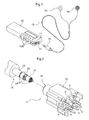
jack 11 is provided in amobile audio device 12 as shown inFig. 1 , and includes aplug inlet 17 for receiving aplug 15 connected to a pair of stereo-type earphones 14 or headphones (not shown) through acable 13. Such amobile audio device 12 includes a plurality ofcontrol switches 12A operable to play and stop audio data stored in thedevice 12 and further to control the volume of sound. In the present embodiment, thejack 11 will be described as provided in themobile audio device 12. However, the scope of the present invention is not limited to such an application. Thejack 11 in accordance with the present invention may be used in mobile phones or mounted on other electric appliances. -
Fig. 2 shows theplug 15 insertable into thejack 11 of the present invention. Theplug 15 includes atip 21 provided at a distal end thereof to act as an electrode for stereo audio signals outputted to the left earphone. Theplug 15 further includes aring 22 acting as an electrode for stereo audio signals outputted to the right earphone, and asleeve 23, thering 22 and thesleeve 23 being arranged in the mentioned order from adjacent the distal end of the plug.Insulating rings 24 are mounted between thetip 21 and thering 22 for insulating one from the other. A further insulatingring 24 is provided between thering 22 and thesleeve 23 as well. Thesleeve 23 is connected to a shield layer used for protecting the right and left stereo audio signals from outside noise in thecable 13. Thus, thetip 21 andring 22 are connected to the jack for transmitting audio signals from themobile audio device 12 to theearphones 14 through thecable 13. Thesleeve 23 is connected to have the same potential as the ground of themobile audio device 12. - The
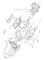
plug inlet 17 is provided in abody 16 of thejack 11 for receiving theplug 15. Outside of the body 16 (the side facing away from theplug inlet 17 inFig. 2 ) are provided a plurality ofterminal electrodes 1 to 7 connected to a plurality of electrodes provided inside the body, respectively. Theseterminal electrodes 1 to 7 are insulated from one another by aseparator 8 formed of an insulating material for preventing short-circuits of those electrodes. Further, each of theterminal electrodes 1 to 7 includes a soldered portion (not shown) formed thereon to facilitate wiring with the exterior. -
Fig. 3 is an exploded view of thejack 11 showing the terminal electrodes and the like. Thejack 11 includes aspring 1, atip spring 2, aring spring 3, a first B-armature 4, a first T-armature 5, a second B-armature 6 and a second T-armature 7, all of which act as the electrodes. Since thesleeve 23 is connected to have the same potential as the ground as noted above, thespring 1 for contacting thesleeve 23 will be referred to as theearth spring 1 and described in detail hereinafter. - The
earth spring 1 according to the present invention is movable under its spring action and includes an earthspring fixing portion 1A provided in aproximal part 100 thereof for fixing theearth spring 1 to thebody 16 of thejack 11. At afree end part 101 of the earth spring is provided apressing portion 1B which is bent for pressing a side surface of theplug 15 when theearth spring 1 contacts thesleeve 23 of theplug 15 inserted into thejack 11. Also, as shown inFig. 3 , theearth spring 1 includes afirst contact portion 1C at a distal end thereof extending from thepressing portion 1B and bent at a substantially central portion thereof. Further, thefree end part 101 has aslot 1D formed therein with an opening edge acting as asecond contact portion 1E. As shown inFig. 3 , a boundary portion defined between theproximal part 100 and thefree end part 101 is also bent. Thus, thefirst contact portion 1C and thesecond contact portion 1E are arranged along theplug inlet 17 at opposite sides of thepressing portion 1B. -
Fig. 4 is a prospective view of thejack 11 and theearth spring 1 showing the relationship therebetween. Thebody 16 includes afirst opening 31 and asecond opening 32 formed parallel to each other adjacent the inlet opening of theplug inlet 17 for receiving theplug 15. Abar 30 is formed between thefirst opening 31 and thesecond opening 32, to have aprojection 33 formed at a distal end thereof to extend through theslot 1D of theearth spring 1. Thebar 30 and theprojection 33 act together as a guide mechanism for preventing out-of-plane displacement of thepressing portion 1B from a predetermined position where theearth spring 1 is movable with reference to theproximal part 100 when theplug 15 is inserted and thepressing portion 1B presses the side surface of theplug 15. -
Fig. 5(a) is a side view of theearth spring 1 and thebody 16 showing how these elements are held with each other, whileFig. 5(b) is a bottom view thereof. It should be noted that thebar 30 and theprojection 33 are made of a reinforced resin. Thus, even when a torsional force occurs as theplug 15 is inserted to apply a twisting force to theearth spring 1, theprojection 33 made of the reinforced resin extends through theslot 1D of theearth spring 1, which allows outer surfaces of thebar 30 and theprojection 33 to act as a retainingportion 102. Not only is theplug 15 is pressed by thepressing portion 1B, both thefirst contact portion 1C and thesecond contact portion 1E contact thebar 30, thereby preventing poor contact resulting from out-of-plane displacement between thepressing portion 1B and thesleeve 23 which should properly contact each other. -
Fig. 6 is a circuit diagram showing connection among the terminal electrodes of thejack 11. As noted above, thejack 11 includes theearth spring 1,tip spring 2,ring spring 3, first B-armature 4, first T-armature 5, second B-armature 6 and second T-armature 7. When theplug 15 is not inserted into theplug inlet 17, the fist B-armature 4 and first T-armature 5 are electrically connected to each other, and the second B-armature 6 and second T-armature 7 are also electrically connected to each other as shown inFig. 6(a) . On the other hand, when theplug 15 is inserted into theplug inlet 17, the first B-armature 4 and first T-armature 5 are disconnected from each other, and the second B-armature 6 and second T-armature 7 are also disconnected from each other as shown inFig. 6(b) . The details will be described later. -
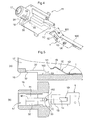
Fig. 7 shows thejack 11 viewed from the side where the terminal electrodes formed outside thejack 11 are provided (from the side facing away from theplug inlet 17 inFig. 2 ).Fig. 8(a) shows thejack 11 taken along the line VIII-VIII ofFig. 7 without the plug being inserted. Inside thejack 11 are thetip spring 2 to be connected, along with theearth spring 1, to thetip 21 of theplug 15, and thering spring 3 to be connected to thering 22 of theplug 15. Theearth spring 1 is fixed to thebody 16 by the earthspring fixing portion 1A. Similarly, thetip spring 2 andring spring 3 are fixed to thebody 16 by a tipspring fixing portion 2A and a ringspring fixing portion 3A, respectively. -
Fig. 8(b) shows thejack 11 taken along the line VIII-VIII ofFig. 7 with the plug being inserted. Thetip 21 contacts tipcontact portions 2B when theplug 15 is inserted. Then, thering 22 contacts aring contact portion 3B while thesleeve 23 contacts thepressing portion 1B of theearth spring 1. Theearth spring 1 is pressed by theplug 15 by virtue of its spring action, whereby thefirst contact portion 1C and thesecond contact portion 1E contact thebar 30. It should be noted that a conventional jack is not provided with thesecond contact portion 1E, which brings thepressing portion 1B into contact thesleeve 23 and allows only thefirst contact portion 1C to contact thebar 30. Thus, the three points provided by thepressing portion 1B,first contact portion 1C and earthspring fixing portion 1A constitute a plate spring. On the other hand, according to thejack 11 of the present invention, thefirst contact portion 1C andsecond contact portion 1E arranged at opposite sides across thepressing portion 1B provide two points for contacting thebar 30, and these three points constitute the plate spring noted above. In comparison between the present invention and the conventional art, a distance between thepressing portion 1B andfirst contact portion 1C is the same while a distance between thepressing portion 1B and the earthspring fixing portion 1A in the prior art corresponds to the decreased distance between thepressing portion 1B and thesecond contact portion 1E in the present invention. Since the plate spring shape is formed to have a small distance, the posture of the spring is stabilized thereby to enhance the strength against torsional forces. -
Fig. 9 is a sectional view of thejack 11 taken along the line IX-IX ofFig. 7 without the plug being inserted. The first B-armature 4 contacts the first T-armature 5 while the second B-armature 6 contacts the second T-armature 7. Theseparator 8 is provided in the central portion of the jack assembly. When theplug 15 is inserted, theseparator 8 receives a pressing force to expand in the direction of arrows shown inFig. 9 . Due to this pressing force, theseparator 8 expands the first T-armature 5 and second T-armature 7 outward. As a result, the first T-armature 5 is disengaged from the first B-armature 4 and the second T-armature 7 is also disengaged from the second B-armature 6. - According to the above embodiment, the second contact portion is formed in the
slot 1D. However, the scope of the present invention is not limited to this arrangement. Naturally, for instance,cutout portions 35 may be provided as shown inFig. 10 instead of the opening such as theslot 1D. With such an arrangement, as shown inFigs. 11(a) and 11(b) , twobars 30 are provided to extend from thebody 16 thereby to hold theearth spring 1 therebetween. This allows thepressing portion 1B to press thesleeve 23 while thefirst contact portion 1C and thesecond contact portion 1E contact thebars 30 as in the above-noted embodiment. Thus, naturally, it is possible to secure the functions and effects of the present invention for providing a countermeasure against a torsional force - In
Fig. 10 , thecutout portions 35 are provided at the opposite sides of theearth spring 1. However, the scope of the present invention is not limited to this arrangement. For example, it is also possible to provide asingle cutout portion 35 at only one side of theearth spring 1 and dispense with the otherside cutout portion 35, thereby allowing theearth spring 1 to be pressed and fixed directly to the body. - According to the first embodiment, the electrodes provided for the
plug 15 include thetip 21,ring 22 andsleeve 23. However, the scope of the present invention is not limited to this arrangement. For example, even if only the two electrodes, thetip 21 andsleeve 23, are provided, it is possible, naturally, to enhance the countermeasure against a torsional force according to the present invention by using thepressing portion 1B,first contact portion 1C andsecond contact portion 1E. The present invention is also applicable where the number of terminal electrodes is increased as where a remote controller is provided between theearphones 14 and plug 15. - In the first embodiment, the
earth spring 1 acts as one of the electrodes. However, the scope of the present invention is not limited to this arrangement. For example, theearth spring 1 may be provided to simply act as a reinforcing jig, instead of the electrode, operative against a torsional force. - According to the first embodiment, the
pressing portion 1B,first contact portion 1C andsecond contact portion 1E contact thesleeve 30 andbar 30, respectively, to enhance the strength against a torsional force. However, the scope of the present invention is not limited to this arrangement. Naturally, for example, it is possible to allow an edge opposed to the edge of theslot 1D acting as thesecond contact portion 1E to act as a third contact portion and contact thebar 30, thereby enhancing the strength against a torsional force. - Further, the
projection 33 acting as the guide mechanism is formed along theplug inlet 17 in the first embodiment. However, the scope of the present invention is not limited to this arrangement. For example, it is also possible to provide theprojection 33 to extend across the plug inlet in a direction from an outer periphery toward the center of the plug inlet. With this arrangement, the position of thesecond contact portion 1E is shifted to the opposite edge of the slot in, which makes it possible to secure the functions and effects of the present invention for counteracting a torsional force by using thesecond contact portion 1E as well as thepressing portion 1B and thefirst contact portion 1C.
Claims (5)
- A jack including a plug inlet (17) for receiving a plug (15) having at least one electrode formed thereon for electrical signals, the jack comprising:an elongated spring (1) having a free end part (101) with a pressing portion capable of pressing a side surface of the inserted plug (15), and a proximal end part (100) fixed to the jack;characterized by
a retaining portion (102) capable of contacting a first contact portion (1C) and a second contact portion (1E) arranged at opposite sides thereof along a direction of inserting the plug when the plug (15) is inserted into the jack. - A jack as claimed in Claim 1 characterized in that the jack further comprises a guide mechanism for preventing out-of-plane displacement of the pressing portion from a predetermined rocking plane defined by the spring (1) rockable about the proximal end part (100) when the plug is inserted into the jack.
- A jack as claimed in Claim 2, characterized in that the guide mechanism includes a projection (33) provided in the jack and extending through an opening formed in the spring (1).
- A jack as claimed in Claim 3, characterized in that the projection (33) is formed along an extending direction of the plug inlet (17), and wherein the retaining portion (102) is formed on an outer surface of the projection (33).
- A jack as claimed in any one of Claims 1 to 4, characterized in that the spring (1) is an electrode electrically connectable to the plug.
Applications Claiming Priority (1)
| Application Number | Priority Date | Filing Date | Title |
|---|---|---|---|
| JP2006347451A JP2008159425A (en) | 2006-12-25 | 2006-12-25 | Jack |
Publications (2)
| Publication Number | Publication Date |
|---|---|
| EP1939992A2 true EP1939992A2 (en) | 2008-07-02 |
| EP1939992A3 EP1939992A3 (en) | 2009-05-13 |
Family
ID=39247158
Family Applications (1)
| Application Number | Title | Priority Date | Filing Date |
|---|---|---|---|
| EP07022808A Withdrawn EP1939992A3 (en) | 2006-12-25 | 2007-11-24 | Jack |
Country Status (7)
| Country | Link |
|---|---|
| US (1) | US20080280499A1 (en) |
| EP (1) | EP1939992A3 (en) |
| JP (1) | JP2008159425A (en) |
| KR (1) | KR20080059513A (en) |
| CN (1) | CN101212110A (en) |
| CA (1) | CA2609833A1 (en) |
| TW (1) | TW200828698A (en) |
Cited By (4)
| Publication number | Priority date | Publication date | Assignee | Title |
|---|---|---|---|---|
| US8491332B1 (en) | 2012-01-26 | 2013-07-23 | Volex Plc | Slim C5/C6 coupler |
| WO2013110333A1 (en) * | 2012-01-26 | 2013-08-01 | Volex Plc | Slim c5/c6 coupler |
| EP2894729A4 (en) * | 2012-09-07 | 2016-04-20 | Hosiden Corp | Connector and electronic device provided with same |
| GB2560325A (en) * | 2017-03-07 | 2018-09-12 | Jaguar Land Rover Ltd | Electrical connector |
Families Citing this family (8)
| Publication number | Priority date | Publication date | Assignee | Title |
|---|---|---|---|---|
| CN201075522Y (en) * | 2007-06-11 | 2008-06-18 | 富士康(昆山)电脑接插件有限公司 | Electric Connector |
| US7708604B2 (en) * | 2008-05-01 | 2010-05-04 | Apple Inc. | Mechanism for constraining the movement of an audio jack |
| KR101136735B1 (en) | 2010-10-20 | 2012-04-19 | 한국단자공업 주식회사 | Connector for earphone jack |
| US8545274B2 (en) * | 2010-12-02 | 2013-10-01 | Molex Incorporated | Filtering assembly and modular jack using same |
| JP5878363B2 (en) * | 2011-12-26 | 2016-03-08 | 日本圧着端子製造株式会社 | Jack |
| CN103579796B (en) | 2012-08-06 | 2016-03-02 | 富士康(昆山)电脑接插件有限公司 | Audio connector |
| TWI633726B (en) * | 2017-11-09 | 2018-08-21 | 徐振健 | Multi-stage signal transmission connector |
| CN113964594B (en) * | 2021-10-25 | 2022-08-16 | 安徽江淮汽车集团股份有限公司 | Wire harness plug-in with locking structure |
Citations (2)
| Publication number | Priority date | Publication date | Assignee | Title |
|---|---|---|---|---|
| JPS5662680U (en) | 1979-10-22 | 1981-05-27 | ||
| JP2000340311A (en) | 1999-05-31 | 2000-12-08 | Mitsumi Electric Co Ltd | Electric connector |
Family Cites Families (16)
| Publication number | Priority date | Publication date | Assignee | Title |
|---|---|---|---|---|
| US4037913A (en) * | 1975-02-13 | 1977-07-26 | Magnetic Controls Company | Printed circuit jack |
| JPS59138185U (en) * | 1983-03-04 | 1984-09-14 | ホシデン株式会社 | jack |
| JPH0312231Y2 (en) * | 1986-09-22 | 1991-03-22 | ||
| JPH0449834Y2 (en) * | 1988-05-16 | 1992-11-24 | ||
| US5338215A (en) * | 1993-03-19 | 1994-08-16 | Molex Incorporated | Jack assembly including a contact switching system |
| TW371120U (en) * | 1997-04-08 | 1999-09-21 | Hon Hai Prec Ind Co Ltd | Joint structure of plug |
| US5893767A (en) * | 1997-05-30 | 1999-04-13 | The Whitaker Corporation | Electrical connector having a switch |
| JP3265262B2 (en) * | 1998-05-22 | 2002-03-11 | エスエムケイ株式会社 | Jack |
| TW430192U (en) * | 1998-06-25 | 2001-04-11 | Hon Hai Prec Ind Co Ltd | Connector with a receiving hole |
| US6062885A (en) * | 1999-04-23 | 2000-05-16 | Molex Incorporated | Electrical switch assembly |
| JP3546162B2 (en) * | 2000-02-14 | 2004-07-21 | ホシデン株式会社 | Multi-pole connector |
| TW482355U (en) * | 2001-03-20 | 2002-04-01 | Hon Hai Prec Ind Co Ltd | Socket connector |
| JP2003308933A (en) * | 2002-04-18 | 2003-10-31 | Hosiden Corp | Jack |
| TWM249324U (en) * | 2002-04-30 | 2004-11-01 | Hon Hai Prec Ind Co Ltd | Audio jack |
| CN2682647Y (en) * | 2003-11-19 | 2005-03-02 | 富士康(昆山)电脑接插件有限公司 | Connector assembly |
| US7031486B2 (en) * | 2004-05-26 | 2006-04-18 | Excel Cell Electronic Co., Ltd. | Earphone jack |
-
2006
- 2006-12-25 JP JP2006347451A patent/JP2008159425A/en active Pending
-
2007
- 2007-08-27 TW TW096131696A patent/TW200828698A/en unknown
- 2007-11-06 CA CA002609833A patent/CA2609833A1/en not_active Abandoned
- 2007-11-24 EP EP07022808A patent/EP1939992A3/en not_active Withdrawn
- 2007-11-30 US US11/998,840 patent/US20080280499A1/en not_active Abandoned
- 2007-12-24 CN CNA2007101600898A patent/CN101212110A/en active Pending
- 2007-12-24 KR KR1020070136034A patent/KR20080059513A/en not_active Application Discontinuation
Patent Citations (2)
| Publication number | Priority date | Publication date | Assignee | Title |
|---|---|---|---|---|
| JPS5662680U (en) | 1979-10-22 | 1981-05-27 | ||
| JP2000340311A (en) | 1999-05-31 | 2000-12-08 | Mitsumi Electric Co Ltd | Electric connector |
Cited By (6)
| Publication number | Priority date | Publication date | Assignee | Title |
|---|---|---|---|---|
| US8491332B1 (en) | 2012-01-26 | 2013-07-23 | Volex Plc | Slim C5/C6 coupler |
| WO2013110333A1 (en) * | 2012-01-26 | 2013-08-01 | Volex Plc | Slim c5/c6 coupler |
| CN104471801A (en) * | 2012-01-26 | 2015-03-25 | 豪利士公开有限公司 | Slim c5/c6 coupler |
| EP2894729A4 (en) * | 2012-09-07 | 2016-04-20 | Hosiden Corp | Connector and electronic device provided with same |
| GB2560325A (en) * | 2017-03-07 | 2018-09-12 | Jaguar Land Rover Ltd | Electrical connector |
| GB2560325B (en) * | 2017-03-07 | 2020-08-05 | Jaguar Land Rover Ltd | Electrical connector |
Also Published As
| Publication number | Publication date |
|---|---|
| JP2008159425A (en) | 2008-07-10 |
| US20080280499A1 (en) | 2008-11-13 |
| TW200828698A (en) | 2008-07-01 |
| EP1939992A3 (en) | 2009-05-13 |
| KR20080059513A (en) | 2008-06-30 |
| CN101212110A (en) | 2008-07-02 |
| CA2609833A1 (en) | 2008-06-25 |
Similar Documents
| Publication | Publication Date | Title |
|---|---|---|
| EP1939992A2 (en) | Jack | |
| JP3156497U (en) | Electrical connector | |
| TWI255083B (en) | Jack | |
| JP3173283U (en) | Electrical connector | |
| US7976347B2 (en) | Multifunctional electrical connector | |
| US6312274B1 (en) | Electrical connector | |
| EP2348583B1 (en) | Cable connecting apparatus | |
| JPWO2007000814A1 (en) | Connectors, circuit boards and electronic devices | |
| US9979112B2 (en) | Press-type connector | |
| CN107809021B (en) | Electrical connector | |
| JP2015056209A (en) | Terminal for electric connector and electric connector | |
| JP4807312B2 (en) | Multipole coaxial connector | |
| CN106410541B (en) | Electrical connector assembly | |
| CN109888546B (en) | Connector of electronic product and electronic equipment | |
| JP5890217B2 (en) | Electrical connector | |
| KR200293414Y1 (en) | Earphone socket | |
| US6503106B1 (en) | Electric jack | |
| JP3039595B2 (en) | Connector pin for electrical connection | |
| JP4308941B2 (en) | Receiver with terminal and mobile communication device using receiver with terminal | |
| JP4225942B2 (en) | Receptacle connector and electrical connector having the same | |
| JP6634153B2 (en) | Signal transmission equipment | |
| JP6906178B2 (en) | Switch device and mobile | |
| KR200280041Y1 (en) | Earphone socket conneted with three pole plug or four pole plug | |
| JP5370069B2 (en) | Attachment for charging device and charging device | |
| KR101675924B1 (en) | Connector assembly for controller of earphone |
Legal Events
| Date | Code | Title | Description |
|---|---|---|---|
| PUAI | Public reference made under article 153(3) epc to a published international application that has entered the european phase |
Free format text: ORIGINAL CODE: 0009012 |
|
| AK | Designated contracting states |
Kind code of ref document: A2 Designated state(s): AT BE BG CH CY CZ DE DK EE ES FI FR GB GR HU IE IS IT LI LT LU LV MC MT NL PL PT RO SE SI SK TR |
|
| AX | Request for extension of the european patent |
Extension state: AL BA HR MK RS |
|
| PUAL | Search report despatched |
Free format text: ORIGINAL CODE: 0009013 |
|
| AK | Designated contracting states |
Kind code of ref document: A3 Designated state(s): AT BE BG CH CY CZ DE DK EE ES FI FR GB GR HU IE IS IT LI LT LU LV MC MT NL PL PT RO SE SI SK TR |
|
| AX | Request for extension of the european patent |
Extension state: AL BA HR MK RS |
|
| RIC1 | Information provided on ipc code assigned before grant |
Ipc: H01R 24/04 20060101ALI20090404BHEP Ipc: H01R 13/26 20060101AFI20090404BHEP |
|
| AKX | Designation fees paid | ||
| STAA | Information on the status of an ep patent application or granted ep patent |
Free format text: STATUS: THE APPLICATION IS DEEMED TO BE WITHDRAWN |
|
| 18D | Application deemed to be withdrawn |
Effective date: 20091114 |
|
| REG | Reference to a national code |
Ref country code: DE Ref legal event code: 8566 |