EP1939435A1 - Ignition device for internal combustion engine - Google Patents
Ignition device for internal combustion engine Download PDFInfo
- Publication number
- EP1939435A1 EP1939435A1 EP06811530A EP06811530A EP1939435A1 EP 1939435 A1 EP1939435 A1 EP 1939435A1 EP 06811530 A EP06811530 A EP 06811530A EP 06811530 A EP06811530 A EP 06811530A EP 1939435 A1 EP1939435 A1 EP 1939435A1
- Authority
- EP
- European Patent Office
- Prior art keywords
- ignition
- fail
- signal
- spark plugs
- internal combustion
- Prior art date
- Legal status (The legal status is an assumption and is not a legal conclusion. Google has not performed a legal analysis and makes no representation as to the accuracy of the status listed.)
- Granted
Links
- 238000002485 combustion reaction Methods 0.000 title claims abstract description 32
- 238000003745 diagnosis Methods 0.000 claims abstract description 11
- 230000007257 malfunction Effects 0.000 description 10
- 238000001514 detection method Methods 0.000 description 6
- 238000010586 diagram Methods 0.000 description 3
- 230000008054 signal transmission Effects 0.000 description 3
- 239000003990 capacitor Substances 0.000 description 2
- 230000003111 delayed effect Effects 0.000 description 2
- 238000000034 method Methods 0.000 description 2
- 230000005540 biological transmission Effects 0.000 description 1
- 230000000694 effects Effects 0.000 description 1
Images


Classifications
-
- F—MECHANICAL ENGINEERING; LIGHTING; HEATING; WEAPONS; BLASTING
- F02—COMBUSTION ENGINES; HOT-GAS OR COMBUSTION-PRODUCT ENGINE PLANTS
- F02P—IGNITION, OTHER THAN COMPRESSION IGNITION, FOR INTERNAL-COMBUSTION ENGINES; TESTING OF IGNITION TIMING IN COMPRESSION-IGNITION ENGINES
- F02P17/00—Testing of ignition installations, e.g. in combination with adjusting; Testing of ignition timing in compression-ignition engines
- F02P17/12—Testing characteristics of the spark, ignition voltage or current
-
- F—MECHANICAL ENGINEERING; LIGHTING; HEATING; WEAPONS; BLASTING
- F02—COMBUSTION ENGINES; HOT-GAS OR COMBUSTION-PRODUCT ENGINE PLANTS
- F02P—IGNITION, OTHER THAN COMPRESSION IGNITION, FOR INTERNAL-COMBUSTION ENGINES; TESTING OF IGNITION TIMING IN COMPRESSION-IGNITION ENGINES
- F02P15/00—Electric spark ignition having characteristics not provided for in, or of interest apart from, groups F02P1/00 - F02P13/00 and combined with layout of ignition circuits
- F02P15/02—Arrangements having two or more sparking plugs
-
- F—MECHANICAL ENGINEERING; LIGHTING; HEATING; WEAPONS; BLASTING
- F02—COMBUSTION ENGINES; HOT-GAS OR COMBUSTION-PRODUCT ENGINE PLANTS
- F02P—IGNITION, OTHER THAN COMPRESSION IGNITION, FOR INTERNAL-COMBUSTION ENGINES; TESTING OF IGNITION TIMING IN COMPRESSION-IGNITION ENGINES
- F02P15/00—Electric spark ignition having characteristics not provided for in, or of interest apart from, groups F02P1/00 - F02P13/00 and combined with layout of ignition circuits
- F02P15/08—Electric spark ignition having characteristics not provided for in, or of interest apart from, groups F02P1/00 - F02P13/00 and combined with layout of ignition circuits having multiple-spark ignition, i.e. ignition occurring simultaneously at different places in one engine cylinder or in two or more separate engine cylinders
Definitions
- the present invention relates to an ignition apparatus for an internal combustion engine.
- Patent Document 1 Japanese Patent Application Laid-Open No. S63-205460 (Patent Document 1) describes that, in an internal combustion engine which includes plural cylinders each provided with one spark plug for an ignition thereof, an ignition control signal (ignition signal) is output at different timing for each spark plug of the cylinder so that the ignition control signals of the respective spark plugs of the cylinders do not overlap with each other.
- an ignition control signal ignition signal
- Patent Document 2 discloses an ignition apparatus for an internal combustion engine, wherein the ignition apparatus outputs an ignition signal from an ECU to an igniter, and detects an ignition state based on a fail signal returned from the igniter.
- a single signal line is employed as both a signal line for the ignition signal and a signal line for the fail signal; and when the fail signal overlaps with the ignition signal, the level of the fail signal is lowered relative to the level of the ignition signal.
- an output timing of the ignition signal is made different for each spark plug of the cylinder so that the ignition signals for different spark plugs of the cylinders do not overlap with each other.
- the returning fail signals corresponding to the respective ignition signals do not overlap with each other on entering the IGF port in the ignition apparatus, whereby an accurate diagnosis can be made for each spark plug with the single IGF port.
- Patent Document 1 does not presuppose application in a multi-spark plugs ignition apparatus provided with plural spark plugs controlled to be ignited simultaneously.
- the technique of Patent Document 1 is applied to a multi-spark plugs ignition apparatus, in which the number of IGF ports for failure detection is smaller than the number of spark plugs (for example, a system having only one IGF port), if the ignition signals are output simultaneously, plural fail signals overlap with each other on entering the IGF port, whereby the diagnosis of coils and spark plugs may not be made accurately.
- An object of the present invention is to provide an ignition apparatus for an internal combustion engine provided with plural spark plugs for each cylinder, wherein an accurate diagnosis of the spark plugs can be realized.
- An ignition apparatus for an internal combustion engine is an ignition apparatus for an internal combustion engine provided with plural spark plugs for each cylinder, and the ignition apparatus includes an input port that receives a fail signal generated corresponding to each of the plural spark plugs for a diagnosis of the spark plugs, wherein an input timing to the input port is set differently timewise for each of the plural fail signals.
- an ignition timing is set differently timewise for each of the plural spark plugs.
- a time elapsed after an ignition timing of the spark plug until an input of the fail signal corresponding to the spark plug into the input port is made different timewise for each of the plural spark plugs.
- the ignition timing of the spark plug for which the time is long is set later than the ignition timing of the spark plug for which the time is short.
- a delay element or a delay circuit is provided in a signal line which conveys part of the plural fail signals up to the input port.
- an accurate diagnosis of spark plugs can be made for an internal combustion engine that is provided with plural spark plugs for each cylinder.
- a four-cylinder engine 10 includes cylinders each having two spark plugs among spark plugs 21 to 28. Specifically, a first cylinder 11 is provided with two spark plugs 21 and 22; and similarly, a second cylinder 12 is provided with two spark plugs 23 and 24; a third cylinder 13 is provided with two spark plugs 25 and 26; and a fourth cylinder 14 is provided with two spark plugs 27 and 28.
- the spark plugs 21 to 28 are connected to secondary coils of ignition coils 31 to 38, respectively.
- Primary coils of the ignition coils 31 to 38 are connected to ignition-signal output ports IGT1A 41 to IGT4B 48, respectively, of an ECU 40.
- ignition signals electric currents
- IGT1A 41 to IGT4B 48 When the ignition signals (electric currents) are supplied from the ignition-signal output ports IGT1A 41 to IGT4B 48 to the primary coils of the ignition coils 31 to 38, high voltage is generated in the secondary coils of the ignition coils 31 to 38, and the spark plugs 21 to 28 are ignited.
- the fail signal is supplied to a single failure-detecting IGF port 49 of the ECU 40 via a shared fail-signal line 50 in the ignition apparatus.
- the fail signal is generated on a trailing edge of the ignition signal in each ignition device. Therefore, when the plural spark plugs 21 to 28 are to be ignited in the first embodiment, different output timings are set for the ignition signals, so that the ignition occurs at different times. Thus, the fail signals corresponding to the plural spark plugs 21 to 28 are prevented from overlapping with each other on entering the single IGF port 49.
- a fail signal S3 generated on a trailing edge of the ignition signal S1 corresponding to the spark plug 21 enters the IGF port 49 at different timing from the entrance of a fail signal S4 generated on a trailing edge of the ignition signal S2 corresponding to the spark plug 22 to the IGF port 49.
- each fail signal always enters the IGF port 49 at a different time from the entrance of the other fail signals into the IGF port 49. Therefore, when a malfunction of the ignition device (including the coil and the spark plug) is detected, it can be accurately distinguished whether the malfunction occurs in the ignition device including the spark plug 21 and the coil 31 or in the ignition device including the spark plug 22 and the coil 32.
- fail signals corresponding to the first spark plugs 21, 23, 25, and 27 of the respective cylinders are supplied into the failure-detecting IGF port 49 of the ECU 40 via a first fail-signal line 51, whereas fail signals corresponding to the second spark plugs 22, 24, 26, and 28 of the respective cylinders are supplied into the failure-detecting IGF port 49 via a second fail-signal line 52.
- a delay circuit 60 is connected to the second fail-signal line 52.
- the delay circuit 60 includes two inverters 61 and 62 connected in series and a grounded capacitor 63 connected at an input side of the inverter 61. A signal is delayed while passing through the two inverters 61 and 62 connected in series.
- the fail signal is generated on a trailing edge of the ignition signal commonly for all the ignition devices according to the second embodiment.
- the fail signal passing through the second fail-signal line 52 and the delay circuit 60 is input to the IGF port 49 at a delayed timing from the input of the fail signal passing through the first fail-signal line 51.
- the ignition signals may be output at the same timing so as to make a concurrent ignition.
- an output of the ignition signal S1 supplied from the ignition-signal output port IGT1A to the spark plug 21 and an output of the ignition signal S2 supplied from the ignition-signal output port IGT1B to the spark plug 22 are simultaneous.
- the fail signal S3 generated on the trailing edge of the ignition signal S1 corresponding to the spark plug 21 and the fail signal S4 generated on the trailing edge of the ignition signal S2 corresponding to the spark plug 22 are generated in the same time period.
- the input of the fail signal S4 into the IGF port 49 lags behind the input of the fail signal S3 by a delay time set by the delay circuit 60.
- the fail signals S3 and S4 always enter the IGF port 49 at different timings, it is possible, when the malfunction is detected in an ignition device (including the coil and the spark plug), to accurately distinguish whether a malfunction occurs in the ignition device including the spark plug 21 and the coil 31 or in the ignition device including the spark plug 22 and the coil 32.
- a position where the delay circuit 60 is arranged is not limited to the position shown in FIG. 3 .
- the fail signals corresponding to the respective first spark plugs 21, 23, 25, and 27 of the cylinders pass through the first fail-signal line 51
- the fail signals corresponding to the respective second spark plugs 22, 24, 26, and 28 of the cylinder pass through the second fail-signal line 52
- the delay circuit 60 is connected to the second fail-signal line 52. If the ignition signals are output to the first spark plugs 21, 23, 25, and 27 of the plural cylinders simultaneously, signal transmission time is same for all the signals; and hence, the corresponding fail signals enter the IGF port 49 simultaneously. Therefore, it is difficult to accurately identify the ignition device which causes the malfunction.
- the third embodiment relates to the second embodiment described above.
- the spark plug 21 and the spark plug 22 are ignited simultaneously, whereas in the third embodiment, the spark plug 21 and the spark plug 22 are ignited at different times.
- the ignition of the spark plug 22 which is connected to a fail-signal transmission path in which the delay circuit 60 is connected, lags behind the ignition of the spark plug 21.
- the output of the ignition signal S2 from the ignition-signal output port IGT1B to the spark plug 22 lags behind the output of the ignition signal S1 from the ignition-signal output port IGT1A to the spark plug 21. Accordingly, the generation of the fail signal S4 on a trailing edge of the ignition signal S2 corresponding to the spark plug 22 lags behind the generation of the fail signal S3 on a trailing edge of the ignition signal S1 corresponding to the spark plug 21.
- the fail signal S4 further lags behind the fail signal S3 while passing through the delay circuit 60, the time difference between the input of the fail signal S3 and the input of the fail signal S4 into the IGF port 49 increases in comparison with that in the second embodiment (in which the ignition signals S1 and S2 are output simultaneously).
- the fail signals S3 and S4 are always supplied to the IGF port 49 at different times, whereby when malfunction is detected in the ignition device (including the coil and the spark plug), it can be accurately distinguished whether the malfunction occurs in the ignition device including the spark plug 21 and the coil 31, or in the ignition device including the spark plug 22 and the coil 32.
- the difference in the ignition timing may be offset by the delay time generated in the delay circuit 60, and the difference in the input timing of the fail signal S3 and the fail signal S4 to the IGF port 49 may be eliminated. Even when the difference is not eliminated, it may become less.
- the fail signals S3 and S4 are detected at a short interval, and the failure detection needs to be performed at a short time interval, which necessitates increased accuracy of detection circuit.
- the output of the ignition signal S2 is made to lag behind the output of the ignition signal S1 in the third embodiment.
- the ignition timing can be changed flexibly for the spark plugs 21 and 22 of the same cylinder according to circumstances. Specifically, no matter whether the spark plugs 21 and 22 are ignited simultaneously (second embodiment) or the spark plugs 21 and 22 are ignited at different times (third embodiment), the fail signals S3 and S4 enter the IGF port 49 at different times, whereby the diagnosis of the coils 31 and 32, and the spark plugs 21 and 22 can be made accurately.
- a substantially simultaneous ignition of the spark plugs 21 and 22 can be realized when the phase difference between the ignition timings of the spark plugs 21 and 22 is set small. Even if there is only a small phase difference between the ignition times of the spark plugs 21 and 22, as far as there is a phase difference, a difference between the input times of the fail signals S3 and S4 into the IGF port 49 can be secured, and the fail signals S3 and S4 can be detected separately, whereby the diagnosis of each ignition device can be made accurately.
- an ignition apparatus for an internal combustion engine is useful when the internal combustion engine is provided with plural spark plugs for each cylinder, and more particularly, is suitable for making an accurate diagnosis of the spark plugs.
Landscapes
- Engineering & Computer Science (AREA)
- Chemical & Material Sciences (AREA)
- Combustion & Propulsion (AREA)
- Mechanical Engineering (AREA)
- General Engineering & Computer Science (AREA)
- Ignition Installations For Internal Combustion Engines (AREA)
- Combined Controls Of Internal Combustion Engines (AREA)
Abstract
Description
- The present invention relates to an ignition apparatus for an internal combustion engine.
- Japanese Patent Application Laid-Open No.
S63-205460 - Japanese Patent Application Laid-Open No.
H08-128381 -
- Patent Document 1: Japanese Patent Application Laid-Open No.
S63-205460 - Patent Document 2: Japanese Patent Application Laid-Open No.
H08-128381 - In a conventional internal combustion engine provided with a single spark plug for each cylinder and a single, shared IGF port (IGF detection device) for all cylinders for failure detection, an output timing of the ignition signal is made different for each spark plug of the cylinder so that the ignition signals for different spark plugs of the cylinders do not overlap with each other. Thus, the returning fail signals corresponding to the respective ignition signals do not overlap with each other on entering the IGF port in the ignition apparatus, whereby an accurate diagnosis can be made for each spark plug with the single IGF port.
- When the internal combustion engine is provided with plural spark plugs for each cylinder, however, plural spark plugs corresponding to one cylinder may be ignited simultaneously, resulting in concurrent return of the fail signals; then, at an occurrence of malfunction, a single IGF port is not sufficient to identify the spark plug which causes the malfunction. It is possible to provide plural IGF ports for failure detection in the internal combustion engine provided with plural spark plugs for each cylinder so that each ignition device can be checked for proper ignition. Such an arrangement, however, increases required costs and spaces.
- The technique disclosed in
Patent Document 1 does not presuppose application in a multi-spark plugs ignition apparatus provided with plural spark plugs controlled to be ignited simultaneously. When the technique ofPatent Document 1 is applied to a multi-spark plugs ignition apparatus, in which the number of IGF ports for failure detection is smaller than the number of spark plugs (for example, a system having only one IGF port), if the ignition signals are output simultaneously, plural fail signals overlap with each other on entering the IGF port, whereby the diagnosis of coils and spark plugs may not be made accurately. - An object of the present invention is to provide an ignition apparatus for an internal combustion engine provided with plural spark plugs for each cylinder, wherein an accurate diagnosis of the spark plugs can be realized.
- An ignition apparatus for an internal combustion engine according to the present invention is an ignition apparatus for an internal combustion engine provided with plural spark plugs for each cylinder, and the ignition apparatus includes an input port that receives a fail signal generated corresponding to each of the plural spark plugs for a diagnosis of the spark plugs, wherein an input timing to the input port is set differently timewise for each of the plural fail signals.
- In the ignition apparatus for the internal combustion engine according to the present invention, an ignition timing is set differently timewise for each of the plural spark plugs.
- In the ignition apparatus for the internal combustion engine according to the present invention, a time elapsed after an ignition timing of the spark plug until an input of the fail signal corresponding to the spark plug into the input port is made different timewise for each of the plural spark plugs.
- In the ignition apparatus for the internal combustion engine according to the present invention, the ignition timing of the spark plug for which the time is long is set later than the ignition timing of the spark plug for which the time is short.
- In the ignition apparatus for the internal combustion engine according to the present invention, a delay element or a delay circuit is provided in a signal line which conveys part of the plural fail signals up to the input port.
- According to the present invention, an accurate diagnosis of spark plugs can be made for an internal combustion engine that is provided with plural spark plugs for each cylinder.
-
-
FIG. 1 is a schematic configuration diagram of an ignition apparatus for an internal combustion engine according to a first embodiment of the present invention; -
FIG. 2 is a waveform chart of ignition signals and fail signals in the ignition apparatus for the internal combustion engine according to the first embodiment of the present invention; -
FIG. 3 is a schematic configuration diagram of an ignition apparatus for an internal combustion engine according to a second embodiment of the present invention; -
FIG. 4 is diagram of a detailed configuration of a delay circuit in the ignition apparatus for the internal combustion engine according to the second embodiment of the present invention; -
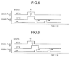
FIG. 5 is a waveform chart of ignition signals and fail signals in the ignition apparatus for the internal combustion engine according to the second embodiment of the present invention; and -
FIG. 6 is a waveform chart of ignition signals and fail signals in an ignition apparatus for an internal combustion engine according to a third embodiment of the present invention. -
- 10
- Engine
- 11
- First Cylinder
- 12
- Second Cylinder
- 13
- Third Cylinder
- 14
- Fourth Cylinder
- 21
- Spark Plug
- 22
- Spark Plug
- 23
- Spark Plug
- 24
- Spark Plug
- 25
- Spark Plug
- 26
- Spark Plug
- 27
- Spark Plug
- 28
- Spark Plug
- 31
- Ignition Coil
- 32
- Ignition Coil
- 33
- Ignition Coil
- 34
- Ignition Coil
- 35
- Ignition Coil
- 36
- Ignition Coil
- 37
- Ignition Coil
- 38
- Ignition Coil
- 40
- ECU
- 41
- Ignition-Signal Output Port IGT1A
- 42
- Ignition-Signal Output Port IGT1B
- 43
- Ignition-Signal Output Port IGT2A
- 44
- Ignition-Signal Output Port IGT2B
- 45
- Ignition-Signal Output Port IGT3A
- 46
- Ignition-Signal Output Port IGT3B
- 47
- Ignition-Signal Output Port IGT4A
- 48
- Ignition-Signal Output Port IGT4B
- 49
- IGF Port
- 50
- Fail-Signal Line
- 51
- First Fail-Signal Line
- 52
- Second Fail-Signal Line
- 60
- Delay Circuit
- 61
- Inverter
- 62
- Inverter
- 63
- Capacitor
- S1
- Ignition Signal
- S2
- Ignition Signal
- S3
- Fail Signal
- S4
- Fail Signal
- Exemplary embodiments of the present invention will be described in detail below with reference to the accompanying drawings.
- An ignition apparatus for an internal combustion engine according to a first embodiment will be described with reference to
FIGS. 1 and 2 . As shown inFIG. 1 , a four-cylinder engine 10 includes cylinders each having two spark plugs amongspark plugs 21 to 28. Specifically, afirst cylinder 11 is provided with twospark plugs second cylinder 12 is provided with twospark plugs third cylinder 13 is provided with twospark plugs fourth cylinder 14 is provided with twospark plugs - The spark plugs 21 to 28 are connected to secondary coils of
ignition coils 31 to 38, respectively. Primary coils of the ignition coils 31 to 38 are connected to ignition-signal output ports IGT1A 41 to IGT4B 48, respectively, of anECU 40. When the ignition signals (electric currents) are supplied from the ignition-signal output ports IGT1A 41 to IGT4B 48 to the primary coils of the ignition coils 31 to 38, high voltage is generated in the secondary coils of the ignition coils 31 to 38, and the spark plugs 21 to 28 are ignited. The fail signal is supplied to a single failure-detectingIGF port 49 of theECU 40 via a shared fail-signal line 50 in the ignition apparatus. - In the first embodiment, the fail signal is generated on a trailing edge of the ignition signal in each ignition device. Therefore, when the
plural spark plugs 21 to 28 are to be ignited in the first embodiment, different output timings are set for the ignition signals, so that the ignition occurs at different times. Thus, the fail signals corresponding to theplural spark plugs 21 to 28 are prevented from overlapping with each other on entering thesingle IGF port 49. - Specifically, as shown in
FIG. 2 , there is a phase difference between an output of an ignition signal S1 which is supplied from the ignition-signal output port IGT1A to thespark plug 21 and an output of an ignition signal S2 which is supplied from the ignition-signal output port IGT1B to thespark plug 22. Therefore, a fail signal S3 generated on a trailing edge of the ignition signal S1 corresponding to thespark plug 21 enters theIGF port 49 at different timing from the entrance of a fail signal S4 generated on a trailing edge of the ignition signal S2 corresponding to thespark plug 22 to theIGF port 49. - Thus, even when fail signals corresponding respectively to the
plural spark plugs 21 to 28 are supplied to thesingle IGF port 49 via the single fail-signal line 50, each fail signal always enters theIGF port 49 at a different time from the entrance of the other fail signals into theIGF port 49. Therefore, when a malfunction of the ignition device (including the coil and the spark plug) is detected, it can be accurately distinguished whether the malfunction occurs in the ignition device including thespark plug 21 and thecoil 31 or in the ignition device including thespark plug 22 and thecoil 32. - Next, a second embodiment will be described with reference to
FIGS. 3 to 5 .
In the second embodiment, the description of elements common to those of the first embodiment will not be repeated and elements different from those of the first embodiment alone will be described. - As shown in
FIG. 3 , fail signals corresponding to the first spark plugs 21, 23, 25, and 27 of the respective cylinders are supplied into the failure-detectingIGF port 49 of theECU 40 via a first fail-signal line 51, whereas fail signals corresponding to the second spark plugs 22, 24, 26, and 28 of the respective cylinders are supplied into the failure-detectingIGF port 49 via a second fail-signal line 52. Adelay circuit 60 is connected to the second fail-signal line 52. - As shown in
FIG. 4 , thedelay circuit 60 includes twoinverters capacitor 63 connected at an input side of theinverter 61. A signal is delayed while passing through the twoinverters - Similarly to the first embodiment, the fail signal is generated on a trailing edge of the ignition signal commonly for all the ignition devices according to the second embodiment. The fail signal passing through the second fail-
signal line 52 and thedelay circuit 60, however, is input to theIGF port 49 at a delayed timing from the input of the fail signal passing through the first fail-signal line 51. When theplural spark plugs 21 to 28 are to be ignited in the second embodiment, the ignition signals may be output at the same timing so as to make a concurrent ignition. - Specifically, as shown in
FIG. 5 , an output of the ignition signal S1 supplied from the ignition-signal output port IGT1A to thespark plug 21 and an output of the ignition signal S2 supplied from the ignition-signal output port IGT1B to thespark plug 22 are simultaneous. Thus, the fail signal S3 generated on the trailing edge of the ignition signal S1 corresponding to thespark plug 21 and the fail signal S4 generated on the trailing edge of the ignition signal S2 corresponding to thespark plug 22 are generated in the same time period. However, the input of the fail signal S4 into theIGF port 49 lags behind the input of the fail signal S3 by a delay time set by thedelay circuit 60. - As can be seen from above, since the fail signals S3 and S4 always enter the
IGF port 49 at different timings, it is possible, when the malfunction is detected in an ignition device (including the coil and the spark plug), to accurately distinguish whether a malfunction occurs in the ignition device including thespark plug 21 and thecoil 31 or in the ignition device including thespark plug 22 and thecoil 32. - In the second embodiment, a position where the
delay circuit 60 is arranged is not limited to the position shown inFIG. 3 . In the configuration as shown inFIG. 3 , the fail signals corresponding to the respective first spark plugs 21, 23, 25, and 27 of the cylinders pass through the first fail-signal line 51, the fail signals corresponding to the respective second spark plugs 22, 24, 26, and 28 of the cylinder pass through the second fail-signal line 52, and thedelay circuit 60 is connected to the second fail-signal line 52. If the ignition signals are output to the first spark plugs 21, 23, 25, and 27 of the plural cylinders simultaneously, signal transmission time is same for all the signals; and hence, the corresponding fail signals enter theIGF port 49 simultaneously. Therefore, it is difficult to accurately identify the ignition device which causes the malfunction. Similarly, if the ignition signals are output to the second spark plugs 22, 24, 26, and 28 of the plural cylinders simultaneously, signal transmission time is same for all the signals; and hence, the corresponding fail signals enter theIGF port 49 simultaneously. And therefore, it is difficult to accurately identify the ignition device which causes the malfunction. To deal with the above inconveniences, it is necessary to arrange a delay circuit in a signal line for each of the fail signals corresponding respectively to theplural spark plugs 21 to 28, to which the ignition signals may be supplied simultaneously, so that the signal transmission time is different on each signal line. - Next, a third embodiment will be described.
The third embodiment relates to the second embodiment described above. - In the following, a circuit configuration having the same configuration as the configuration according to the second embodiment shown in
FIG. 3 will be described as an example of the third embodiment. In the second embodiment, thespark plug 21 and thespark plug 22 are ignited simultaneously, whereas in the third embodiment, thespark plug 21 and thespark plug 22 are ignited at different times. When thespark plug 21 and thespark plug 22 are ignited at different times, the ignition of thespark plug 22, which is connected to a fail-signal transmission path in which thedelay circuit 60 is connected, lags behind the ignition of thespark plug 21. - Specifically, as shown in
FIG. 6 , the output of the ignition signal S2 from the ignition-signal output port IGT1B to thespark plug 22 lags behind the output of the ignition signal S1 from the ignition-signal output port IGT1A to thespark plug 21. Accordingly, the generation of the fail signal S4 on a trailing edge of the ignition signal S2 corresponding to thespark plug 22 lags behind the generation of the fail signal S3 on a trailing edge of the ignition signal S1 corresponding to thespark plug 21. Further, since the fail signal S4 further lags behind the fail signal S3 while passing through thedelay circuit 60, the time difference between the input of the fail signal S3 and the input of the fail signal S4 into theIGF port 49 increases in comparison with that in the second embodiment (in which the ignition signals S1 and S2 are output simultaneously). - Thus, the fail signals S3 and S4 are always supplied to the
IGF port 49 at different times, whereby when malfunction is detected in the ignition device (including the coil and the spark plug), it can be accurately distinguished whether the malfunction occurs in the ignition device including thespark plug 21 and thecoil 31, or in the ignition device including thespark plug 22 and thecoil 32. - On the contrary, if the ignition of the
spark plug 21 lags behind the ignition of thespark plug 22, the difference in the ignition timing may be offset by the delay time generated in thedelay circuit 60, and the difference in the input timing of the fail signal S3 and the fail signal S4 to theIGF port 49 may be eliminated. Even when the difference is not eliminated, it may become less. When there is only a slight difference in the input timing, the fail signals S3 and S4 are detected at a short interval, and the failure detection needs to be performed at a short time interval, which necessitates increased accuracy of detection circuit. In view of the above, the output of the ignition signal S2 is made to lag behind the output of the ignition signal S1 in the third embodiment. - As can be seen from the second and the third embodiment, when the configuration shown in
FIG. 3 is adopted, the ignition timing can be changed flexibly for the spark plugs 21 and 22 of the same cylinder according to circumstances. Specifically, no matter whether the spark plugs 21 and 22 are ignited simultaneously (second embodiment) or the spark plugs 21 and 22 are ignited at different times (third embodiment), the fail signals S3 and S4 enter theIGF port 49 at different times, whereby the diagnosis of thecoils - Further, in the configuration without the
delay circuit 60 as in the first embodiment, a substantially simultaneous ignition of the spark plugs 21 and 22 can be realized when the phase difference between the ignition timings of the spark plugs 21 and 22 is set small. Even if there is only a small phase difference between the ignition times of the spark plugs 21 and 22, as far as there is a phase difference, a difference between the input times of the fail signals S3 and S4 into theIGF port 49 can be secured, and the fail signals S3 and S4 can be detected separately, whereby the diagnosis of each ignition device can be made accurately. - As can be seen from above, an ignition apparatus for an internal combustion engine according to the present invention is useful when the internal combustion engine is provided with plural spark plugs for each cylinder, and more particularly, is suitable for making an accurate diagnosis of the spark plugs.
Claims (5)
- An ignition apparatus for an internal combustion engine provided with plural spark plugs for each cylinder, the ignition apparatus comprising:an input port that receives a fail signal generated corresponding to each of the plural spark plugs for a diagnosis of the spark plugs, whereinan input timing to the input port is set differently timewise for each of the plural fail signals.
- The ignition apparatus for the internal combustion engine according to claim 1, wherein
an ignition timing is set differently timewise for each of the plural spark plugs. - The ignition apparatus for the internal combustion engine according to claim 1, wherein
a time elapsed after an ignition timing of the spark plug until an input of the fail signal corresponding to the spark plug into the input port is made different timewise for each of the plural spark plugs. - The ignition apparatus for the internal combustion engine according to claim 3, wherein
the ignition timing of the spark plug for which the time is long is set later than the ignition timing of the spark plug for which the time is short. - The ignition apparatus for the internal combustion engine according to claim 3 or 4, wherein
a delay element or a delay circuit is provided in a signal line which conveys part of the plural fail signals up to the input port.
Applications Claiming Priority (2)
| Application Number | Priority Date | Filing Date | Title |
|---|---|---|---|
| JP2005302243A JP4466533B2 (en) | 2005-10-17 | 2005-10-17 | Ignition device for internal combustion engine |
| PCT/JP2006/320218 WO2007046270A1 (en) | 2005-10-17 | 2006-10-10 | Ignition device for internal combustion engine |
Publications (3)
| Publication Number | Publication Date |
|---|---|
| EP1939435A1 true EP1939435A1 (en) | 2008-07-02 |
| EP1939435A4 EP1939435A4 (en) | 2009-11-25 |
| EP1939435B1 EP1939435B1 (en) | 2011-11-23 |
Family
ID=37962366
Family Applications (1)
| Application Number | Title | Priority Date | Filing Date |
|---|---|---|---|
| EP06811530A Not-in-force EP1939435B1 (en) | 2005-10-17 | 2006-10-10 | Ignition device for internal combustion engine |
Country Status (3)
| Country | Link |
|---|---|
| EP (1) | EP1939435B1 (en) |
| JP (1) | JP4466533B2 (en) |
| WO (1) | WO2007046270A1 (en) |
Families Citing this family (1)
| Publication number | Priority date | Publication date | Assignee | Title |
|---|---|---|---|---|
| KR102586926B1 (en) * | 2018-11-27 | 2023-10-10 | 현대자동차주식회사 | Advanced Engine Combustion Method and Engine Ignition Output System Thereof |
Family Cites Families (5)
| Publication number | Priority date | Publication date | Assignee | Title |
|---|---|---|---|---|
| JPS58192970A (en) * | 1982-05-07 | 1983-11-10 | Automob Antipollut & Saf Res Center | Misfire detecting device in engine ignition device |
| JPH03286186A (en) * | 1990-03-30 | 1991-12-17 | Mazda Motor Corp | Ignition device for engine |
| DE19645383B4 (en) * | 1996-11-04 | 2004-04-29 | Daimlerchrysler Ag | Method for operating an Otto internal combustion engine with internal mixture formation |
| JP2002266739A (en) * | 2001-03-12 | 2002-09-18 | Mazda Motor Corp | Engine ignition timing control device |
| US6559647B1 (en) * | 2001-11-02 | 2003-05-06 | Ford Global Technologies, Llc | Diagnosing spark plugs malfunction in a dual plug engine |
-
2005
- 2005-10-17 JP JP2005302243A patent/JP4466533B2/en not_active Expired - Fee Related
-
2006
- 2006-10-10 WO PCT/JP2006/320218 patent/WO2007046270A1/en not_active Ceased
- 2006-10-10 EP EP06811530A patent/EP1939435B1/en not_active Not-in-force
Also Published As
| Publication number | Publication date |
|---|---|
| EP1939435B1 (en) | 2011-11-23 |
| JP2007107509A (en) | 2007-04-26 |
| EP1939435A4 (en) | 2009-11-25 |
| JP4466533B2 (en) | 2010-05-26 |
| WO2007046270A1 (en) | 2007-04-26 |
Similar Documents
| Publication | Publication Date | Title |
|---|---|---|
| JP3474810B2 (en) | Device for detecting combustion state of internal combustion engine | |
| EP0582430B1 (en) | System and method to determine cam phase and cylinder identification for a variable cam timing engine | |
| US7624717B2 (en) | Internal-combustion-engine combustion condition detection apparatus | |
| CN107035561B (en) | Engine synchronization device and control method thereof | |
| JP4736942B2 (en) | Multiple discharge ignition device | |
| CN112368476B (en) | Ignition control system for internal combustion engine | |
| US6550456B1 (en) | Combustion state detection apparatus for internal combustion engine | |
| US4757798A (en) | Electronic distribution backup apparatus | |
| US5410253A (en) | Method of indicating combustion in an internal combustion engine | |
| EP1939435B1 (en) | Ignition device for internal combustion engine | |
| US7617040B2 (en) | Ignition apparatus for internal combustion engine | |
| EP0244830B1 (en) | Electronic ignition signal distributor for automobile engine | |
| US4899579A (en) | Onboard diagnostic system of vehicle ignition system | |
| JPH04219468A (en) | Igniter for internal combustion engine | |
| US20100006066A1 (en) | Variable primary current for ionization | |
| JPH0676791B2 (en) | Ignition device for internal combustion engine | |
| US10197037B2 (en) | Control device | |
| JP2008286090A (en) | Cylinder discrimination device for internal combustion engine | |
| US20050284443A1 (en) | Fuel injection system for an internal combustion engine and method for operating a fuel injection system | |
| US6943554B2 (en) | Ionic current detection apparatus for internal combustion engine | |
| JP4127373B2 (en) | Ion current detection device for internal combustion engine | |
| JPS61255275A (en) | Ignition device for internal-combustion engine | |
| US7367321B2 (en) | Erroneous connection detecting method of ignition devices and apparatus of the same | |
| JPH05223050A (en) | Misfire detecting device for internal combustion engine | |
| KR19980048568U (en) | Engine control device by vehicle cylinder explosion |
Legal Events
| Date | Code | Title | Description |
|---|---|---|---|
| PUAI | Public reference made under article 153(3) epc to a published international application that has entered the european phase |
Free format text: ORIGINAL CODE: 0009012 |
|
| 17P | Request for examination filed |
Effective date: 20070329 |
|
| AK | Designated contracting states |
Kind code of ref document: A1 Designated state(s): DE FR |
|
| DAX | Request for extension of the european patent (deleted) | ||
| RBV | Designated contracting states (corrected) |
Designated state(s): DE FR |
|
| A4 | Supplementary search report drawn up and despatched |
Effective date: 20091026 |
|
| GRAP | Despatch of communication of intention to grant a patent |
Free format text: ORIGINAL CODE: EPIDOSNIGR1 |
|
| GRAS | Grant fee paid |
Free format text: ORIGINAL CODE: EPIDOSNIGR3 |
|
| GRAA | (expected) grant |
Free format text: ORIGINAL CODE: 0009210 |
|
| AK | Designated contracting states |
Kind code of ref document: B1 Designated state(s): DE FR |
|
| REG | Reference to a national code |
Ref country code: DE Ref legal event code: R096 Ref document number: 602006026055 Country of ref document: DE Effective date: 20120119 |
|
| PLBE | No opposition filed within time limit |
Free format text: ORIGINAL CODE: 0009261 |
|
| STAA | Information on the status of an ep patent application or granted ep patent |
Free format text: STATUS: NO OPPOSITION FILED WITHIN TIME LIMIT |
|
| 26N | No opposition filed |
Effective date: 20120824 |
|
| REG | Reference to a national code |
Ref country code: DE Ref legal event code: R097 Ref document number: 602006026055 Country of ref document: DE Effective date: 20120824 |
|
| REG | Reference to a national code |
Ref country code: DE Ref legal event code: R084 Ref document number: 602006026055 Country of ref document: DE Effective date: 20130717 |
|
| REG | Reference to a national code |
Ref country code: FR Ref legal event code: PLFP Year of fee payment: 10 |
|
| PGFP | Annual fee paid to national office [announced via postgrant information from national office to epo] |
Ref country code: FR Payment date: 20150908 Year of fee payment: 10 |
|
| PGFP | Annual fee paid to national office [announced via postgrant information from national office to epo] |
Ref country code: DE Payment date: 20151006 Year of fee payment: 10 |
|
| REG | Reference to a national code |
Ref country code: DE Ref legal event code: R119 Ref document number: 602006026055 Country of ref document: DE |
|
| REG | Reference to a national code |
Ref country code: FR Ref legal event code: ST Effective date: 20170630 |
|
| PG25 | Lapsed in a contracting state [announced via postgrant information from national office to epo] |
Ref country code: DE Free format text: LAPSE BECAUSE OF NON-PAYMENT OF DUE FEES Effective date: 20170503 Ref country code: FR Free format text: LAPSE BECAUSE OF NON-PAYMENT OF DUE FEES Effective date: 20161102 |