EP0244830B1 - Electronic ignition signal distributor for automobile engine - Google Patents
Electronic ignition signal distributor for automobile engine Download PDFInfo
- Publication number
- EP0244830B1 EP0244830B1 EP87106513A EP87106513A EP0244830B1 EP 0244830 B1 EP0244830 B1 EP 0244830B1 EP 87106513 A EP87106513 A EP 87106513A EP 87106513 A EP87106513 A EP 87106513A EP 0244830 B1 EP0244830 B1 EP 0244830B1
- Authority
- EP
- European Patent Office
- Prior art keywords
- cylinder
- signal
- ignition
- signals
- reference position
- Prior art date
- Legal status (The legal status is an assumption and is not a legal conclusion. Google has not performed a legal analysis and makes no representation as to the accuracy of the status listed.)
- Expired - Lifetime
Links
- 230000001360 synchronised effect Effects 0.000 claims description 2
- 238000002485 combustion reaction Methods 0.000 claims 1
- 238000001208 nuclear magnetic resonance pulse sequence Methods 0.000 claims 1
- 238000010586 diagram Methods 0.000 description 4
- 230000000630 rising effect Effects 0.000 description 4
- 230000007257 malfunction Effects 0.000 description 2
- 230000003247 decreasing effect Effects 0.000 description 1
- 230000001419 dependent effect Effects 0.000 description 1
- 238000001514 detection method Methods 0.000 description 1
- 230000036039 immunity Effects 0.000 description 1
- 230000003053 immunization Effects 0.000 description 1
- 230000001960 triggered effect Effects 0.000 description 1
Images


Classifications
-
- F—MECHANICAL ENGINEERING; LIGHTING; HEATING; WEAPONS; BLASTING
- F02—COMBUSTION ENGINES; HOT-GAS OR COMBUSTION-PRODUCT ENGINE PLANTS
- F02P—IGNITION, OTHER THAN COMPRESSION IGNITION, FOR INTERNAL-COMBUSTION ENGINES; TESTING OF IGNITION TIMING IN COMPRESSION-IGNITION ENGINES
- F02P3/00—Other installations
- F02P3/02—Other installations having inductive energy storage, e.g. arrangements of induction coils
- F02P3/04—Layout of circuits
-
- F—MECHANICAL ENGINEERING; LIGHTING; HEATING; WEAPONS; BLASTING
- F02—COMBUSTION ENGINES; HOT-GAS OR COMBUSTION-PRODUCT ENGINE PLANTS
- F02P—IGNITION, OTHER THAN COMPRESSION IGNITION, FOR INTERNAL-COMBUSTION ENGINES; TESTING OF IGNITION TIMING IN COMPRESSION-IGNITION ENGINES
- F02P7/00—Arrangements of distributors, circuit-makers or -breakers, e.g. of distributor and circuit-breaker combinations or pick-up devices
- F02P7/02—Arrangements of distributors, circuit-makers or -breakers, e.g. of distributor and circuit-breaker combinations or pick-up devices of distributors
- F02P7/03—Arrangements of distributors, circuit-makers or -breakers, e.g. of distributor and circuit-breaker combinations or pick-up devices of distributors with electrical means
- F02P7/035—Arrangements of distributors, circuit-makers or -breakers, e.g. of distributor and circuit-breaker combinations or pick-up devices of distributors with electrical means without mechanical switching means
-
- F—MECHANICAL ENGINEERING; LIGHTING; HEATING; WEAPONS; BLASTING
- F02—COMBUSTION ENGINES; HOT-GAS OR COMBUSTION-PRODUCT ENGINE PLANTS
- F02P—IGNITION, OTHER THAN COMPRESSION IGNITION, FOR INTERNAL-COMBUSTION ENGINES; TESTING OF IGNITION TIMING IN COMPRESSION-IGNITION ENGINES
- F02P11/00—Safety means for electric spark ignition, not otherwise provided for
- F02P11/02—Preventing damage to engines or engine-driven gearing
Definitions
- This invention relates to an electronic ignition signal distributor for automobile engine and, particularly, to a fail-safe electronic circuit arrangement for the ignition signal distribution system.
- Such a system is known from US-Patent 3 757 755. It distributes the ignition signals to the ignition devices of the engine by determining the ignition sequence by referring to subsidiary signals.
- One of these signals indicates, whether a cylinder from an EVEN-numbered cylinder block has to be ignited or a cylinder from an ODD-numbered cylinder block.
- the other signals define a pair of cylinders, each of these pairs comprising a cylinder out of an EVEN-numbered cylinder block and a cylinder out of an ODD-numbered cylinder block.
- AND-gates these signals are linked to provide the correct ignition signals.
- These subsidiary signals are delivered by circuits that work similar to a shifting circuit.
- a further ignition signal distribution system having a constitution for preventing the false operation of an electric distributor, due to double count by a counter because of a stop operation of the engine with a reversal rotation is known from JP-A- 59-28751.
- This electronic ignition signal distributor does not protect the ignition signal distribution properly in the event of a false operation, due to a noise or the like, of the counter for determining the cylinder to be ignited, resulting possibly in the ignition of an irrelevant cylinder which is in the suction stroke, for example.
- An object of this invention is to provide an electronic ignition signal distributor for automobile engine capable of at least preventing the erroneous ignition of irrelevant cylinders in the event of a malfunctioning, caused by a noise or the like of the counter which determines the ignition sequence for the cylinders.
- the inventive ignition signal distribution system operates to determine the igniting cylinder not only basing on the ignition sequence counter, but also using a reference position signal and crank angle signal synchronous with the engine rotation and the ignition signal is finally delivered to each cylinder as a result of a logical-product operation between the counter output and the cylinder determination signal, thereby preventing at least the ignition of irrelevant cylinders if the counter should malfunction.
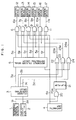
- a reference position detector 1 and crank angle position pulse generator 2 produce a reference position signal 1a and crank angle signal 2a, respectively.
- a cylinder identifying circuit 3 receives these output signals to identify cylinders, and produces a reference cylinder signal 3a for the first cylinder, cylinder identification signal 3b for the 4th cylinder, cylinder identification signal 3c for the 2nd or 5th cylinder and cylinder identification signal 3d for the 3rd or 6th cylinder.
- the reference position signal 1a is a pulse signal rising at a certain angle (e.g., 110°) before the top dead centre of each cylinder.
- the crank angle signal 2a is a pulse train, each pulse being generated at a certain additional rotational angle of the engine (e.g., one pulse per 2°-rotation, or generation of 180 pulses in one engine revolution).
- the reference position detector 1 is designed to produce the reference position signal 1a which has a different pulse width for some cylinders.
- a signal 1a for the first cylinder has a duration in which 16 pulses of the crank angle signal 2a are included
- a signal 1a for the second and fifth cylinders has a duration equivalent to 8 pulses of the signal 2a
- a signal 1a for the third and sixth cylinders has a duration equivalent to 4 pulses
- a signal 1a for the fourth cylinder has a duration equivalent to 12 pulses.
- the reference position signal 1a and the crank angle signal 2a are ANDed by an AND gate 31, and its output is fed to a crank angle pulse counter 32, which counts the number of pulses of the crank angle signal 2a included in the pulse width of the reference position signal 1a.
- the counter 32 produces a reference cylinder signal 3a for the first cylinder upon counting 16 pulses, and produces a 4th cylinder identification signal 3b for the fourth cylinder upon detection of 12 pulses.
- the counter 32 produces an 8-pulse signal 32a for the second and fifth cylinders, and produces 4-pulse signal for the third and sixth cylinders.
- the counter 32 is reset to the initial state in response to the generation of the next reference signal 1a, in such a manner that a pulse-rise detecting circuit 30 produces a narrow (e.g., 2 ⁇ s) clear signal 30a at the rising edge of the reference position signal 1a, as shown in Fig. 3, and this signal clears the crank angle pulse counter 32.
- the above circuit arrangement is intended to identify each cylinder by counting the number of pulses of the crank angle signal 2a in the duration of the reference position signal 1a.
- the 8-pulse signal 32a and 4-pulse signal 32b are each created in periods for multiple cylinders, and therefore signals at irrelevant cylinders must be masked off.
- An AND gate 33 is used to AND the inverted output of the 4th cylinder signal 3b, the inverted output of the reference position signal 1a and the 8-pulse signal 32a so that the 8-pulse signal is reformed to the 2/5th cylinder signal 3c.
- an AND gate 34 takes AND for the 4-pulse signal 32b and the inverted outputs of the 8-pulse signal 32a and reference position signal 1a.
- the above circuit arrangement provides the signals for identifying cylinders.
- the reference cylinder signal 3a detected as described above is fed to a reference cylinder signal distributing circuit 5 in Fig. 1, in which the signal is shifted successively by being triggered at the falling edge of an ignition signal 4a provided by an arithmetic unit 4 including a CPU, which receives the reference position signal 1a and crank angle signal 2a to calculate the ignition signal 4a.
- the reference cylinder signal distributing circuit 5 provides first ignition distributing signals (5a-5f) for cylinders 1 to 6, respectively in accordance with the ignition sequence of each cylinder.
- the ignition signal 4a is distributed to the cylinders by being simply ANDed with the first ignition distribution signals 5a-5f.
- the reference cylinder signal distributing circuit 5 will erroneously respond to the noise and will be clocked to shift the reference position signal.
- the noise causes, at its timing, the 2nd first ignition distribution signal 5b to go from high to low and, at the same time, the 3rd first ignition distribution signal 5c to go high at the time point indicated by B.
- the logical-product operations between the ignition signal 4a and all of the first ignition distribution signals (5a-5f) further involve the cylinder identification signals (3b-3d) by means of AND gates 6 through 11 as shown in Fig. 1, thereby immunizing the system from noises.
- the 3rd cylinder AND gate 8 ANDs the ignition distribution signal 5c for the 3rd cylinder, the ignition signal 4a and the 3/6th second ignition distribution signal 24a derived from the 3/6th cylinder identification signal 3d through an OR gate 24, resulting in a low output as shown by D in Fig. 4, and therefore even if the reference cylinder signal distributing circuit 5 should malfunction due to a noise occurring at the time point indicated by A, an active ignition pulse does not arise at the portion indicated by C.
- the output signals 6a-11a of the AND gates 6-11 are delivered to the respective ignition circuits 12 through 17, each of which includes an ignition coil, a primary voltage switching device connected to the coil, and an ignition plug.
- the 1st cylinder AND gate 6 ANDs the first ignition distribution signal 5a for the 1st cylinder, the 1/4th second ignition distribution signal 24a and the ignition signal 4a to produce the 1st cylinder ignition signal 6a.
- the ignition signals for the remaining cylinders are produced in the same manner.
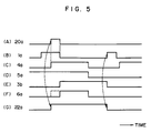
- a flip-flop 21 is provided for the purpose of preventing the 1-6th cylinder ignition signals 6a-11a from being narrowed in their pulse width when the ignition signal 4a overlaps with the reference position signal 1a. It eventually prevents insufficient sparking caused by a decreased current supplied to the ignition coil when the ignition signal would become narrower as the engine speed increases. This is the case shown in the timing chart of Fig.
- the signal overlap is detected to quit the AND operations between the ignition signal 4a and cylinder signals 3b-3d using the AND gate 20, flip-flop 21 and OR gates 22-24.
- the reference position signal 1a is taken AND with the ignition signal 4a by the AND gate 20 to detect the signal overlapping.
- the overlap signal 20a produced by the AND gate 20 triggers at its rising edge the flip-flop 21, which then turns the output to high.
- the output signal of the flip-flop 21 is taken OR with the cylinder identification signals 3b-3d by the OR gates 22-24 to bring the second ignition distribution signals 22a-24a to high, whereby the ignition signals 6a-11a are prevented from being narrowed.
- Fig. 6 shows the second embodiment of this invention, in which common reference symbols are used for the components identical to those shown in Fig. 1.
- the second and fifth cylinders are operated by the same 8-pulse signal without the distinction between the cylinders, and this relation is also the case of the third and sixth cylinders.
- This is based on the reason that if one of each cylinder pair is in the suction stroke, for example, the other cylinder is naturally in the exhaust stroke, and their distinction is practically unnecessary.
- it if it is intended to avoid the possibility of a backfire caused by the ignition in the exhaust stroke, it can be accomplished by providing a distinct pulse width for each of six cylinders.
- the circuit arrangement shown in Fig. 6 operates in principally the same manner as the operation of the foregoing embodiment, except that distinct cylinder identification signal 3A through 3F for identifying each cylinder are generated in this case, thereby providing the noise immunity for the ignition system.
Landscapes
- Engineering & Computer Science (AREA)
- Chemical & Material Sciences (AREA)
- Combustion & Propulsion (AREA)
- Mechanical Engineering (AREA)
- General Engineering & Computer Science (AREA)
- Ignition Installations For Internal Combustion Engines (AREA)
- Combined Controls Of Internal Combustion Engines (AREA)
- Electrical Control Of Ignition Timing (AREA)
Description
- This invention relates to an electronic ignition signal distributor for automobile engine and, particularly, to a fail-safe electronic circuit arrangement for the ignition signal distribution system.
- Such a system is known from US-
Patent 3 757 755. It distributes the ignition signals to the ignition devices of the engine by determining the ignition sequence by referring to subsidiary signals. One of these signals indicates, whether a cylinder from an EVEN-numbered cylinder block has to be ignited or a cylinder from an ODD-numbered cylinder block. The other signals define a pair of cylinders, each of these pairs comprising a cylinder out of an EVEN-numbered cylinder block and a cylinder out of an ODD-numbered cylinder block. By means of AND-gates these signals are linked to provide the correct ignition signals. These subsidiary signals are delivered by circuits that work similar to a shifting circuit. - However, if one of the shifting circuits operates false due to a noise or the like, an irrelevant cylinder can be ignited erroneoulsy, and such an event can damage the engine.
- A further ignition signal distribution system having a constitution for preventing the false operation of an electric distributor, due to double count by a counter because of a stop operation of the engine with a reversal rotation is known from JP-A- 59-28751. This electronic ignition signal distributor, however, does not protect the ignition signal distribution properly in the event of a false operation, due to a noise or the like, of the counter for determining the cylinder to be ignited, resulting possibly in the ignition of an irrelevant cylinder which is in the suction stroke, for example.
- An object of this invention is to provide an electronic ignition signal distributor for automobile engine capable of at least preventing the erroneous ignition of irrelevant cylinders in the event of a malfunctioning, caused by a noise or the like of the counter which determines the ignition sequence for the cylinders.
- In order to achieve the above objective, the inventive ignition signal distribution system operates to determine the igniting cylinder not only basing on the ignition sequence counter, but also using a reference position signal and crank angle signal synchronous with the engine rotation and the ignition signal is finally delivered to each cylinder as a result of a logical-product operation between the counter output and the cylinder determination signal, thereby preventing at least the ignition of irrelevant cylinders if the counter should malfunction.
- The above object is achieved by means of an electronic ignition distribution apparatus in accordance with
independent claim 1, the dependent claims being directed to advantageous embodiments of the present invention. - Fig. 1 is a block diagram showing the arrangement of the inventive electronic ignition signal distributor;
- Fig. 2 is a block diagram showing in detail the
cylinder identifying circuit 3 in Fig. 1; - Fig. 3 is a timing chart showing the operation of the circuit shown in Fig. 2;
- Fig. 4 is a timing chart showing the operation of the circuit arrangement shown in Fig. 1;
- Fig. 5 is a timing chart showing the operation when the reference position signal 1a and
ignition signal 4a overlap with each other; and - Fig. 6 is a block diagram showing the second embodiment of this invention.
- Embodiments of this invention will now be described in detail.
- In Fig. 1 showing in block diagram the circuit arrangement of this invention, a
reference position detector 1 and crank angleposition pulse generator 2 produce a reference position signal 1a andcrank angle signal 2a, respectively. Acylinder identifying circuit 3 receives these output signals to identify cylinders, and produces areference cylinder signal 3a for the first cylinder,cylinder identification signal 3b for the 4th cylinder,cylinder identification signal 3c for the 2nd or 5th cylinder andcylinder identification signal 3d for the 3rd or 6th cylinder. - The operation of the
cylinder identifying circuit 3 will be explained in detail in connection with Fig. 2. and 3 The reference position signal 1a is a pulse signal rising at a certain angle (e.g., 110°) before the top dead centre of each cylinder. Thecrank angle signal 2a is a pulse train, each pulse being generated at a certain additional rotational angle of the engine (e.g., one pulse per 2°-rotation, or generation of 180 pulses in one engine revolution). Thereference position detector 1 is designed to produce the reference position signal 1a which has a different pulse width for some cylinders. For example, a signal 1a for the first cylinder has a duration in which 16 pulses of thecrank angle signal 2a are included, a signal 1a for the second and fifth cylinders has a duration equivalent to 8 pulses of thesignal 2a, a signal 1a for the third and sixth cylinders has a duration equivalent to 4 pulses, and a signal 1a for the fourth cylinder has a duration equivalent to 12 pulses. The reference position signal 1a and thecrank angle signal 2a are ANDed by anAND gate 31, and its output is fed to a crankangle pulse counter 32, which counts the number of pulses of thecrank angle signal 2a included in the pulse width of the reference position signal 1a. For example, thecounter 32 produces areference cylinder signal 3a for the first cylinder upon counting 16 pulses, and produces a 4thcylinder identification signal 3b for the fourth cylinder upon detection of 12 pulses. Thecounter 32 produces an 8-pulse signal 32a for the second and fifth cylinders, and produces 4-pulse signal for the third and sixth cylinders. Thecounter 32 is reset to the initial state in response to the generation of the next reference signal 1a, in such a manner that a pulse-rise detecting circuit 30 produces a narrow (e.g., 2 µs)clear signal 30a at the rising edge of the reference position signal 1a, as shown in Fig. 3, and this signal clears the crankangle pulse counter 32. - The above circuit arrangement is intended to identify each cylinder by counting the number of pulses of the
crank angle signal 2a in the duration of the reference position signal 1a. However, as shown in the timing chart of Fig. 3, the 8-pulse signal 32a and 4-pulse signal 32b are each created in periods for multiple cylinders, and therefore signals at irrelevant cylinders must be masked off. AnAND gate 33 is used to AND the inverted output of the4th cylinder signal 3b, the inverted output of the reference position signal 1a and the 8-pulse signal 32a so that the 8-pulse signal is reformed to the 2/5th cylinder signal 3c. Similarly, anAND gate 34 takes AND for the 4-pulse signal 32b and the inverted outputs of the 8-pulse signal 32a and reference position signal 1a. The above circuit arrangement provides the signals for identifying cylinders. - The
reference cylinder signal 3a detected as described above is fed to a reference cylindersignal distributing circuit 5 in Fig. 1, in which the signal is shifted successively by being triggered at the falling edge of anignition signal 4a provided by anarithmetic unit 4 including a CPU, which receives the reference position signal 1a andcrank angle signal 2a to calculate theignition signal 4a. The reference cylindersignal distributing circuit 5 provides first ignition distributing signals (5a-5f) forcylinders 1 to 6, respectively in accordance with the ignition sequence of each cylinder. - In the conventional system known from JP-A-59-28751, the
ignition signal 4a is distributed to the cylinders by being simply ANDed with the firstignition distribution signals 5a-5f. However, if theignition signal 4a is contaminated by noises, particularly when a noise is superimposed on theignition signal 4a at a point immediately after its rising edge as shown by A in Fig. 4, the reference cylindersignal distributing circuit 5 will erroneously respond to the noise and will be clocked to shift the reference position signal. The noise causes, at its timing, the 2nd firstignition distribution signal 5b to go from high to low and, at the same time, the 3rd firstignition distribution signal 5c to go high at the time point indicated by B. This results in the issuance of the 3rdcylinder ignition signal 8a at an incorrect timing indicated by C. The generation of this improper pulse is the result of logical-product between thesignals - According to the present invention, the logical-product operations between the
ignition signal 4a and all of the first ignition distribution signals (5a-5f) further involve the cylinder identification signals (3b-3d) by means ofAND gates 6 through 11 as shown in Fig. 1, thereby immunizing the system from noises. For example, the 3rd cylinder ANDgate 8 ANDs theignition distribution signal 5c for the 3rd cylinder, theignition signal 4a and the 3/6th secondignition distribution signal 24a derived from the 3/6thcylinder identification signal 3d through anOR gate 24, resulting in a low output as shown by D in Fig. 4, and therefore even if the reference cylindersignal distributing circuit 5 should malfunction due to a noise occurring at the time point indicated by A, an active ignition pulse does not arise at the portion indicated by C. Theoutput signals 6a-11a of the AND gates 6-11 are delivered to therespective ignition circuits 12 through 17, each of which includes an ignition coil, a primary voltage switching device connected to the coil, and an ignition plug. - The 1st cylinder AND
gate 6 ANDs the firstignition distribution signal 5a for the 1st cylinder, the 1/4th secondignition distribution signal 24a and theignition signal 4a to produce the 1stcylinder ignition signal 6a. The ignition signals for the remaining cylinders are produced in the same manner. - A flip-
flop 21 is provided for the purpose of preventing the 1-6thcylinder ignition signals 6a-11a from being narrowed in their pulse width when theignition signal 4a overlaps with the reference position signal 1a. It eventually prevents insufficient sparking caused by a decreased current supplied to the ignition coil when the ignition signal would become narrower as the engine speed increases. This is the case shown in the timing chart of Fig. 5, in which when the reference position signal 1a overlaps with theignition signal 4a, causing the 4thcylinder identification signal 3b to rise at a time point near the falling edge of the reference position signal 1a, the AND operation for the 4thcylinder identification signal 3b andignition signal 4a produces the 1stcylinder ignition signal 6a narrower than the ignition,signal 4a, as shown by the dashed line in Fig. 5. - In order to prevent this impropriety from occuring, the signal overlap is detected to quit the AND operations between the
ignition signal 4a andcylinder signals 3b-3d using theAND gate 20, flip-flop 21 and OR gates 22-24. In operation in more detail, the reference position signal 1a is taken AND with theignition signal 4a by theAND gate 20 to detect the signal overlapping. Theoverlap signal 20a produced by theAND gate 20 triggers at its rising edge the flip-flop 21, which then turns the output to high. The output signal of the flip-flop 21 is taken OR with thecylinder identification signals 3b-3d by the OR gates 22-24 to bring the secondignition distribution signals 22a-24a to high, whereby theignition signals 6a-11a are prevented from being narrowed. By the foregoing circuit arrangement, irrelevant cylinders are not ignited even if the reference cylindersignal distributing circuit 5 should fail due to a noise or the like. - Fig. 6 shows the second embodiment of this invention, in which common reference symbols are used for the components identical to those shown in Fig. 1. In the previous embodiment of Fig. 1, the second and fifth cylinders are operated by the same 8-pulse signal without the distinction between the cylinders, and this relation is also the case of the third and sixth cylinders. This is based on the reason that if one of each cylinder pair is in the suction stroke, for example, the other cylinder is naturally in the exhaust stroke, and their distinction is practically unnecessary. However, if it is intended to avoid the possibility of a backfire caused by the ignition in the exhaust stroke, it can be accomplished by providing a distinct pulse width for each of six cylinders. The circuit arrangement shown in Fig. 6 operates in principally the same manner as the operation of the foregoing embodiment, except that distinct
cylinder identification signal 3A through 3F for identifying each cylinder are generated in this case, thereby providing the noise immunity for the ignition system.
Claims (6)
- An electronic ignition distribution apparatus for a multi-cylinder internal combustion engine, comprising:- a reference position detector (1) coupled with the engine's output shaft generating a reference position signal (1a) at a certain angle before the dead point of each cylinder, a crank angle position pulse generator (2) generating a crank angle signal (2a) in form of a pulse sequence having a frequency corresponding to the rotational speed of the engine and an arithmetic unit (4) providing an ignition signal (4a),- a reference cylinder signal distributing circuit (5) working in response to a reference cylinder signal (3a) which is generated in response to and in synchronism with the reference position signal (1a), said reference cylinder signal providing a reference of the ignition sequence for the plurality of cylinders and in response to said ignition signal (4a) so as to provide first ignition distribution signals (5a-5f) respectively being allocated to a respective cylinder and being set when said cylinder has to be ignited,- a plurality of logical AND-gates (6-11), one input of each AND-gate (6-11) being connected to the outputs of said reference cylinder signal distributing circuit (5) and the output of each AND-gate (6-11) being connected to an ignition device (12-17),characterized in that
it further comprises
a cylinder identifying circuit (3) receiving the signals from said reference position detector (1) and said crank angle position pulse generator (2) and providing in synchronism with said reference position signal (1a) cylinder identification signals (3b-3d) each of which is allocated to one or more cylinders, and that means are provided for producing from said cylinder identification signals (3b-3d) second ignition distribution signals (22a-24a) each of which designates one or more out of a plurality of cylinders and respectively being supplied to those second inputs of said AND-gates which correspond to the designated cylinders. - An apparatus according to claim 1, characterized in that said cylinder identification signals (3b-3d) are respectively ORED with the ignition signals (4a) synchronized with said reference position signal.
- An apparatus according to claim 1 or claim 2, characterized in that said cylinder identifying circuit generates three cylinder identification signals (3b-3d), each of them identifying two cylinders.
- An apparatus according to claim 1 or claim 2, characterized in that said cylinder identifying circuit provides six cylinder identification signals (3a-3f), each of them identifying one cylinder.
- An apparatus according to one of the claims 1 to 4, characterized in that said reference position detector (1) generates a reference position signal (1a) differing in its pulse duration for different cylinders.
- An apparatus according to one of the claims 1 to 5, characterized in that said cylinder identifying circuit (3) comprises a crank angle pulse counter (32) that counts the pulses delivered by said crank angle position pulse generator (2) within one signal of said reference position detector (1), thus obtaining said reference cylinder signal (3a) and said cylinder signals (3b-3d).
Applications Claiming Priority (2)
| Application Number | Priority Date | Filing Date | Title |
|---|---|---|---|
| JP105548/86 | 1986-05-08 | ||
| JP61105548A JPH0639947B2 (en) | 1986-05-08 | 1986-05-08 | Low voltage electronic distribution ignition device |
Publications (3)
| Publication Number | Publication Date |
|---|---|
| EP0244830A2 EP0244830A2 (en) | 1987-11-11 |
| EP0244830A3 EP0244830A3 (en) | 1988-03-30 |
| EP0244830B1 true EP0244830B1 (en) | 1992-07-29 |
Family
ID=14410627
Family Applications (1)
| Application Number | Title | Priority Date | Filing Date |
|---|---|---|---|
| EP87106513A Expired - Lifetime EP0244830B1 (en) | 1986-05-08 | 1987-05-06 | Electronic ignition signal distributor for automobile engine |
Country Status (5)
| Country | Link |
|---|---|
| US (1) | US4726347A (en) |
| EP (1) | EP0244830B1 (en) |
| JP (1) | JPH0639947B2 (en) |
| KR (1) | KR870011369A (en) |
| DE (1) | DE3780694T2 (en) |
Families Citing this family (9)
| Publication number | Priority date | Publication date | Assignee | Title |
|---|---|---|---|---|
| KR910010035B1 (en) * | 1987-05-14 | 1991-12-10 | 미쓰비시전기주식회사 | Ignition timing control device |
| JPH01305161A (en) * | 1988-06-03 | 1989-12-08 | Mitsubishi Electric Corp | Ignition signal distribution circuit for engine |
| US4841932A (en) * | 1988-07-19 | 1989-06-27 | Delco Electronics Corporation | Spark timing control |
| JPH0781547B2 (en) * | 1989-03-08 | 1995-08-30 | 三菱電機株式会社 | Ignition timing control device for internal combustion engine |
| US5027785A (en) * | 1990-04-19 | 1991-07-02 | Motorola, Inc. | Simplified ignition system for multi-cylinder engines |
| JP2569212B2 (en) * | 1990-08-31 | 1997-01-08 | 三菱電機株式会社 | Internal combustion engine ignition control method and apparatus |
| JP2573444B2 (en) * | 1991-09-26 | 1997-01-22 | 株式会社日立製作所 | Ignition device for internal combustion engine |
| GB9309527D0 (en) * | 1993-05-08 | 1993-06-23 | Lucas Ind Plc | Processing circuit |
| US5619968A (en) * | 1994-07-28 | 1997-04-15 | United Technologies Corporation | Electronic ignition system with pre-ignition prevention apparatus and method |
Family Cites Families (9)
| Publication number | Priority date | Publication date | Assignee | Title |
|---|---|---|---|---|
| FR1596981A (en) * | 1968-12-20 | 1970-06-22 | ||
| US3757755A (en) * | 1971-10-14 | 1973-09-11 | Inst Gas Technology | Engine control apparatus |
| FR2374528A1 (en) * | 1976-12-17 | 1978-07-13 | Cii | ELECTRONIC IGNITION SYSTEM AND INTERNAL COMBUSTION ENGINE EQUIPPED WITH SUCH A SYSTEM |
| JPS53143834A (en) * | 1977-05-19 | 1978-12-14 | Mitsubishi Electric Corp | Igniter for multicylinder engine |
| JPS5928751B2 (en) * | 1979-02-07 | 1984-07-16 | 三菱電機株式会社 | internal combustion engine ignition system |
| AT384862B (en) * | 1979-10-01 | 1988-01-25 | Jenbacher Werke Ag | IGNITION DEVICE FOR MULTI-CYLINDER INTERNAL COMBUSTION ENGINES |
| JPS6035161A (en) * | 1983-08-05 | 1985-02-22 | Fujitsu Ten Ltd | Distributor for control device of fuel injection |
| US4649881A (en) * | 1983-08-17 | 1987-03-17 | Electromotive, Inc. | Precision distributorless ignition control system for internal combustion engines |
| JPS6073059A (en) * | 1983-09-28 | 1985-04-25 | Mitsubishi Electric Corp | Igniter for internal-combustion engine |
-
1986
- 1986-05-08 JP JP61105548A patent/JPH0639947B2/en not_active Expired - Fee Related
-
1987
- 1987-05-05 US US07/046,159 patent/US4726347A/en not_active Expired - Lifetime
- 1987-05-06 DE DE8787106513T patent/DE3780694T2/en not_active Expired - Fee Related
- 1987-05-06 EP EP87106513A patent/EP0244830B1/en not_active Expired - Lifetime
- 1987-05-06 KR KR870004398A patent/KR870011369A/en not_active Withdrawn
Also Published As
| Publication number | Publication date |
|---|---|
| DE3780694T2 (en) | 1993-03-11 |
| US4726347A (en) | 1988-02-23 |
| DE3780694D1 (en) | 1992-09-03 |
| EP0244830A3 (en) | 1988-03-30 |
| JPS62261673A (en) | 1987-11-13 |
| JPH0639947B2 (en) | 1994-05-25 |
| EP0244830A2 (en) | 1987-11-11 |
| KR870011369A (en) | 1987-12-23 |
Similar Documents
| Publication | Publication Date | Title |
|---|---|---|
| EP0183771B1 (en) | Reference pulse verification circuit adaptable for engine control | |
| US4797827A (en) | Angular position detector | |
| US4378004A (en) | Engine control system with cylinder identification apparatus | |
| EP0181379B1 (en) | Pulse detector for missing or extra pulses | |
| US4181884A (en) | Rotational position detection device using a reference mark and two sensors spaced integer times apart | |
| JP3474810B2 (en) | Device for detecting combustion state of internal combustion engine | |
| EP0244830B1 (en) | Electronic ignition signal distributor for automobile engine | |
| JP2634253B2 (en) | Cylinder identification device for internal combustion engines | |
| EP0240858A1 (en) | Electronic distribution backup apparatus | |
| US4711227A (en) | Apparatus and method for electronic ignition control | |
| US3543572A (en) | Ignition suppression system | |
| KR0133939B1 (en) | Ignition timing control system of engine with backup function in case of failure | |
| JP2690315B2 (en) | Ignition device and injection device for internal combustion engine | |
| JPH0676791B2 (en) | Ignition device for internal combustion engine | |
| US4795915A (en) | Zero crossing noise-rejecting digital filter | |
| US4899579A (en) | Onboard diagnostic system of vehicle ignition system | |
| US4856489A (en) | Ignition timing control apparatus for an internal combustion engine | |
| US4380980A (en) | Ignition spark timing circuit | |
| EP0624723B1 (en) | Signal processing circuit for use in a control system of an internal combustion engine | |
| JPS5967459A (en) | Method for detecting engine speed of internal combustion engine | |
| JP2570013B2 (en) | Control device for internal combustion engine | |
| EP0682180A2 (en) | Electronic position sensor assembly and control system | |
| JPS62247179A (en) | Engine ignitor | |
| JP3329639B2 (en) | Ignition control backup device | |
| EP1939435B1 (en) | Ignition device for internal combustion engine |
Legal Events
| Date | Code | Title | Description |
|---|---|---|---|
| PUAI | Public reference made under article 153(3) epc to a published international application that has entered the european phase |
Free format text: ORIGINAL CODE: 0009012 |
|
| AK | Designated contracting states |
Kind code of ref document: A2 Designated state(s): DE GB |
|
| PUAL | Search report despatched |
Free format text: ORIGINAL CODE: 0009013 |
|
| AK | Designated contracting states |
Kind code of ref document: A3 Designated state(s): DE GB |
|
| 17P | Request for examination filed |
Effective date: 19880405 |
|
| 17Q | First examination report despatched |
Effective date: 19890915 |
|
| GRAA | (expected) grant |
Free format text: ORIGINAL CODE: 0009210 |
|
| AK | Designated contracting states |
Kind code of ref document: B1 Designated state(s): DE GB |
|
| REF | Corresponds to: |
Ref document number: 3780694 Country of ref document: DE Date of ref document: 19920903 |
|
| PLBE | No opposition filed within time limit |
Free format text: ORIGINAL CODE: 0009261 |
|
| STAA | Information on the status of an ep patent application or granted ep patent |
Free format text: STATUS: NO OPPOSITION FILED WITHIN TIME LIMIT |
|
| 26N | No opposition filed | ||
| REG | Reference to a national code |
Ref country code: GB Ref legal event code: IF02 |
|
| PGFP | Annual fee paid to national office [announced via postgrant information from national office to epo] |
Ref country code: GB Payment date: 20030425 Year of fee payment: 17 |
|
| PGFP | Annual fee paid to national office [announced via postgrant information from national office to epo] |
Ref country code: DE Payment date: 20030605 Year of fee payment: 17 |
|
| PG25 | Lapsed in a contracting state [announced via postgrant information from national office to epo] |
Ref country code: GB Free format text: LAPSE BECAUSE OF NON-PAYMENT OF DUE FEES Effective date: 20040506 |
|
| PG25 | Lapsed in a contracting state [announced via postgrant information from national office to epo] |
Ref country code: DE Free format text: LAPSE BECAUSE OF NON-PAYMENT OF DUE FEES Effective date: 20041201 |
|
| GBPC | Gb: european patent ceased through non-payment of renewal fee |
Effective date: 20040506 |